Influence of Mach Number of Main Flow on Film Cooling Characteristics under Supersonic Condition

Jiangsu Province Key Laboratory of Aerospace Power System, College of Energy and Power, Nanjing University of Aeronautics and Astronautics, Nanjing 210016, China
*
Author to whom correspondence should be addressed.
Symmetry 2021, 13(1), 127; https://0-doi-org.brum.beds.ac.uk/10.3390/sym13010127
Submission received: 9 December 2020
/
Revised: 4 January 2021
/
Accepted: 5 January 2021
/
Published: 13 January 2021
(This article belongs to the Special Issue Mathematical Modeling and Computational Methods in Science and Engineering III)
Abstract
:The flow and heat transfer characteristics of a film jet inclined to different supersonic situations with a varying Mach number of the main flow were numerically investigated. In supersonic situations, complicated waves are generated by the obstacle of the film jet. In this work, extra pressure is exerted onto the film jet, causing better film attachment to the wall. The strengthening of attachment decreases mixing between the main flow and film jet, causing better film cooling. We observed multi-interfacial layered structures caused by the film jet under the complicated effect of shock waves. At the interfaces of the film jet and shock waves, additional pressure is exerted on the film towards the wall. The pressure increases as the Mach number of the main flow increases and contributes to the increased adhesion of the gas film, which causes the cooling enhancement under a supersonic condition. In the vicinity of the film hole exit, a local low pressure region is formed under the influence of the supersonic main flow. An aerodynamic convergent–divergent state was formed in the film hole, devastating the state of supersonic congestion of the film hole and further enhancing the film cooling effect.
1. Introduction
In the previous designs of the engine nozzle, researchers have not yet fully taken into account the cooling requirement of the expansion section. However, in recent years, there have been increasingly higher requirements for the aircraft to be equipped with the infrared stealth of an aero engine. It has become imperative to enhance the cooling of the expansion section of the nozzle, which is one of the main sources of infrared radiation at the back of the engine. At present, the film cooling technology constitutes one of the most widely used cooling technologies in aero engines. The technology has found mature applications in both turbine blades and combustion chambers, which are mainly under a subsonic condition. By comparison, this paper focuses on components such as the nozzle expansion section working in the supersonic flow environment and the film layer interfered by the shock waves and the boundary layer.
Studies on film cooling have been extensively carried out. As early as 1961, Hartnett et al. [1] studied the temperature distribution and heat transfer of surface cooling with a pressure gradient. Subsequently, Bergeles et al. [2] studied the flow and heat transfer in the vicinity of the holes during an injection of double rows of holes on a flat plate. In the 1990s, Bons et al. [3] studied the impact imposed by varying free flow turbulence on the adiabatic efficiency of film cooling. Jiang et al. [4] studied such issues as the inertial term, porosity, and fluid pressure while conducting research on the upward fluid flow in a vertical porous annulus and its corresponding convective heat transfer. Since the beginning of the 21st century, Goldfield and Sargison [5] has introduced the experimental measurement of the engine guide vane, which features a novel geometry of film cooling holes. Rozati and Danesh [6] resorted to a large eddy simulation to study the vortex structure with three different blowing ratios. Zhang et al. [7] numerically simulated the characteristics of the flow and heat transfer of the impingement–effusion cooling system, and compared the effects imposed by varying blowing ratios and hole spacing on cooling efficiency.
In the 1940s, Ferry [8] managed to observe shock waves and boundary layer interference for the first time while studying wing outflow. Since then, numerous scholars have carried out relevant experimental studies [9,10,11,12,13], illustrating the effects imposed by the Mach number in front of the wave on flow separation. In addition, numerous scholars have conducted relevant research from the perspective of numerical simulation. Konopka et al. [14] adopted the method of a large eddy simulation to analyze the interplay between shock wave and supersonic cooling film. The results show that under the influence of shock, a separation zone clearly emerges from the laminar boundary layer and immediately achieves the transition into turbulent flow. Such transition leads to a marked increase in the mixing of free flow and cooling flow, in addition to a sharp decrease in cooling efficiency. Pirozzoli et al. [11] also confirmed the impact imposed by the Mach number on shock wave and boundary layer by using the DNS high-precision simulation. In terms of the conventional issues of boundary layer interference of shock wave, scholars have conducted extensive research through shock wave simulators and summarized relevant empirical formulas accordingly [15,16,17].
In case there is a secondary stream incident on the supersonic main flow, the situation is expected to become more complicated. Dickmann and Lu [18] numerically simulated the three-dimensional flow incident on the supersonic main flow under the secondary flow, and studied the variance of the surface pressure of the plate with the Mach number. Viti et al. [19] adopted RNS to simulate the flow field structure of the main flow supersonic and subflow critical velocities on a flat plate, and they compared the research findings with the experiment results, which are consistent with each other. Zhu and Jiang [20] studied the shock wave structure in the three-dimensional ejector by using the technology of flow visualization. Zhu et al. [21] put forward the model of a shock circle, which involves the use of the shock circle to analyze the velocity distribution of the mixing chamber. Zhang and Bai [22] studied the effectiveness of film cooling in a supersonic mainstream, and they found that the wave could induce an adverse pressure gradient and lead to the decreasing of local cooling effectiveness.
Compared with subsonic film cooling, supersonic film cooling is subject to significant impact imposed by compressibility. In addition, the momentum and energy equations are tightly coupled. Therefore, the mechanism of supersonic film cooling vastly differs from that of subsonic film cooling, and the results obtained from studies on subsonic film cooling cannot be simply extrapolated to supersonic film cooling. Heufer and Olivier [23] adopted a simple ramp model to conduct experimental and numerical studies on hypersonic film cooling. Alzner and Zakkay [24] studied the interplay between shock wave and supersonic film cooling. The research results have shown that the supersonic film can effectively suppress the heating effect of the shock wave on the incident position, which is in contrast with the case without the film. Kanda et al. [25] conducted oil flow experiments by adopting the schlieren method; they observed the impact of shock waves on the supersonic film cooling flow field and found that shock wave could lead to the reduced cooling efficiency. Juhany and Hunt [26] took into account the impact of shock wave on supersonic film cooling in their study, which showed that the cooling efficiency of supersonic film would be reduced due to shock waves.
As widely known to academia, when the pressure drop ratio of the nozzle is higher than the critical pressure ratio, the main flow of the expansion section of the nozzle will be in a supersonic flow state, which features a large velocity gradient and high pressure gradient. In addition, as the operating conditions of the engine vary, the main flow velocity and the cooling gas pressure are subject to a wide range of variation in the expansion section of the binary vector nozzle. Accordingly, researchers find it more difficult to adopt the nozzle model to calculate and analyze the film cooling characteristics in the supersonic main flow environment of the expansion section. Therefore, in this paper, we adopt the flat plate model to elaborate on the influence imposed by the Mach number of the main flow on the flow and cooling characteristics in the downstream of cooling holes in the supersonic state of main flow, which is expected to provide a reference for the design of the film cooling of the expansion section of a binary vector nozzle.
2. Physical Model
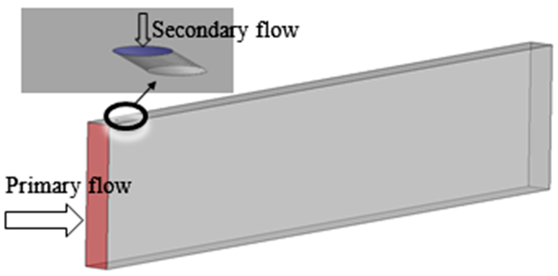
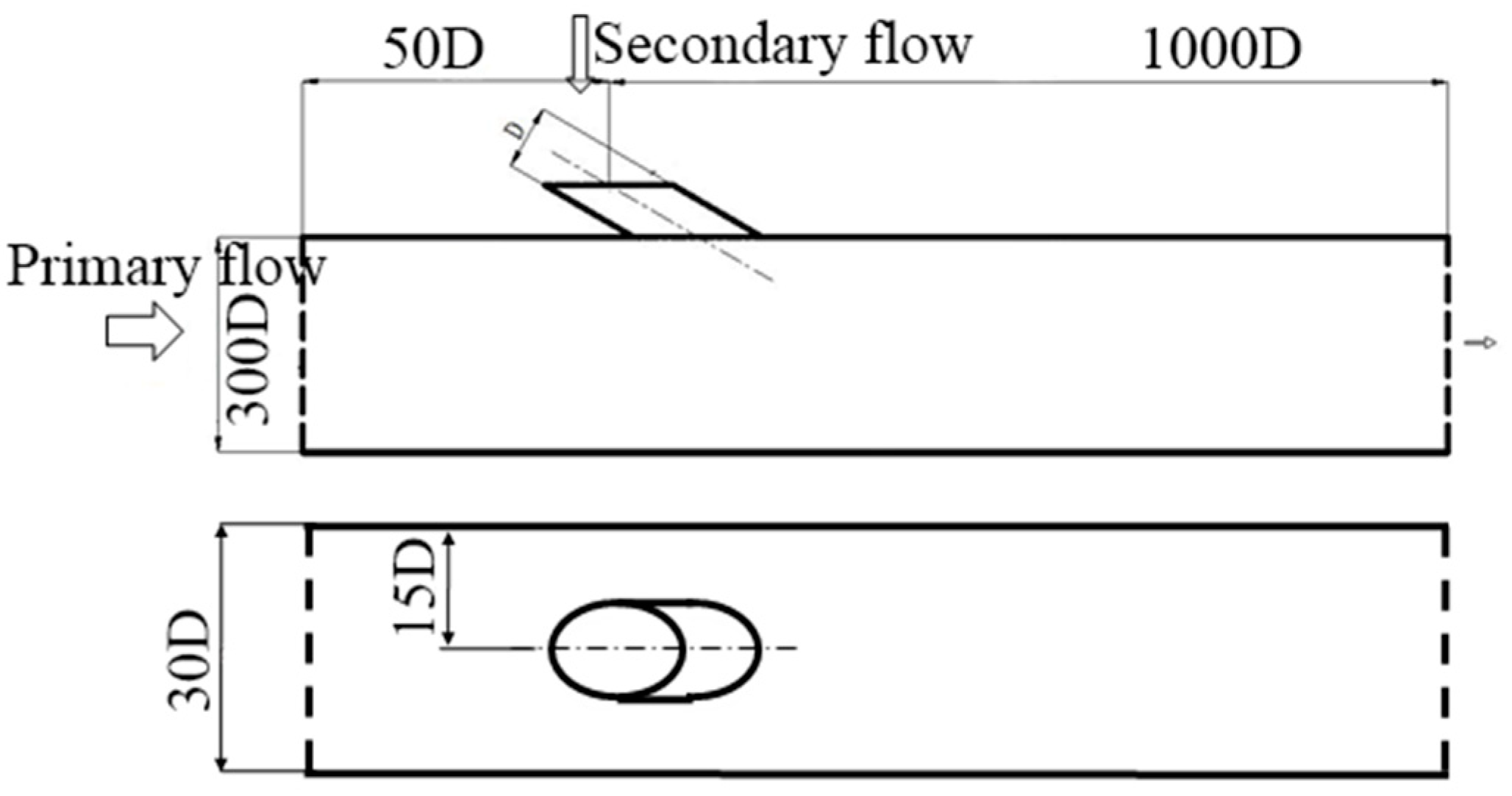
The computational physical model adopted in this study is a single-hole flat plate, which features a cooling hole diameter D = 1 mm and an angle with the wall α = 30°. Figure 1 shows a schematic diagram of the computational model. The flow field of the domain is 150D in total, while the upstream of the hole is 50D and the downstream of the hole is 1000D. The radial length of the domain is 300D, with a 30D along the span wide direction. The details are shown in Figure 2.
3. Computational Domain and Boundary Conditions
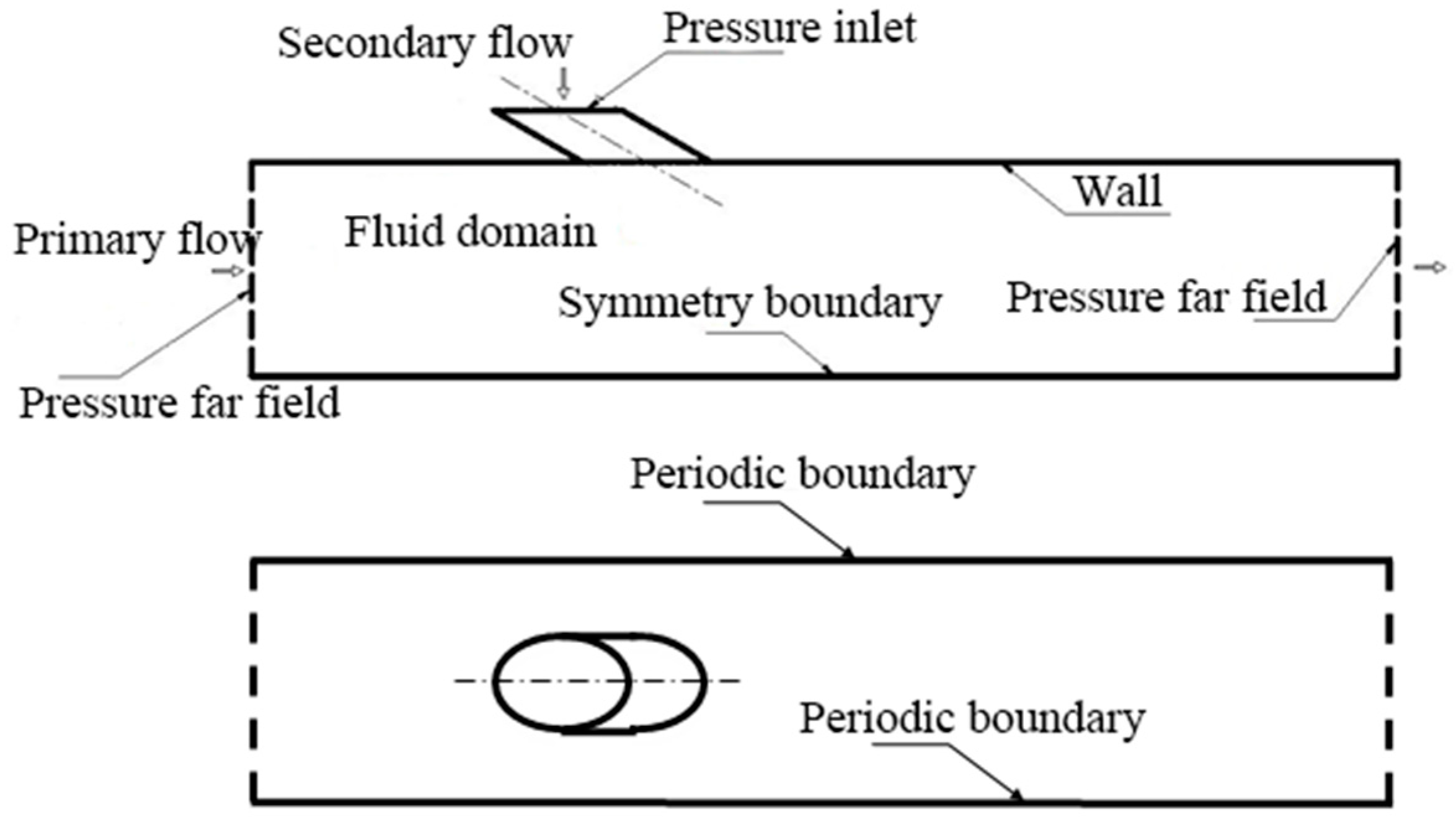
Figure 2 illustrates the schematic diagram of the physical model of the tablet and the size of the computational domain, and Figure 3 illustrates the boundary conditions of calculation. Both the main flow and the film jet are assumed to be filled with compressible ideal gas. The film jet inlet is defined as the pressure inlet; the main flow inlet and exit are defined as the pressure far field, whereas the surfaces are regarded as boundary conditions of the adiabatic wall. Both side-faces are set to be within periodic boundary conditions. Table 1 provides the corresponding computational parameters.
4. Division of Grids and Verification of Grid Independence
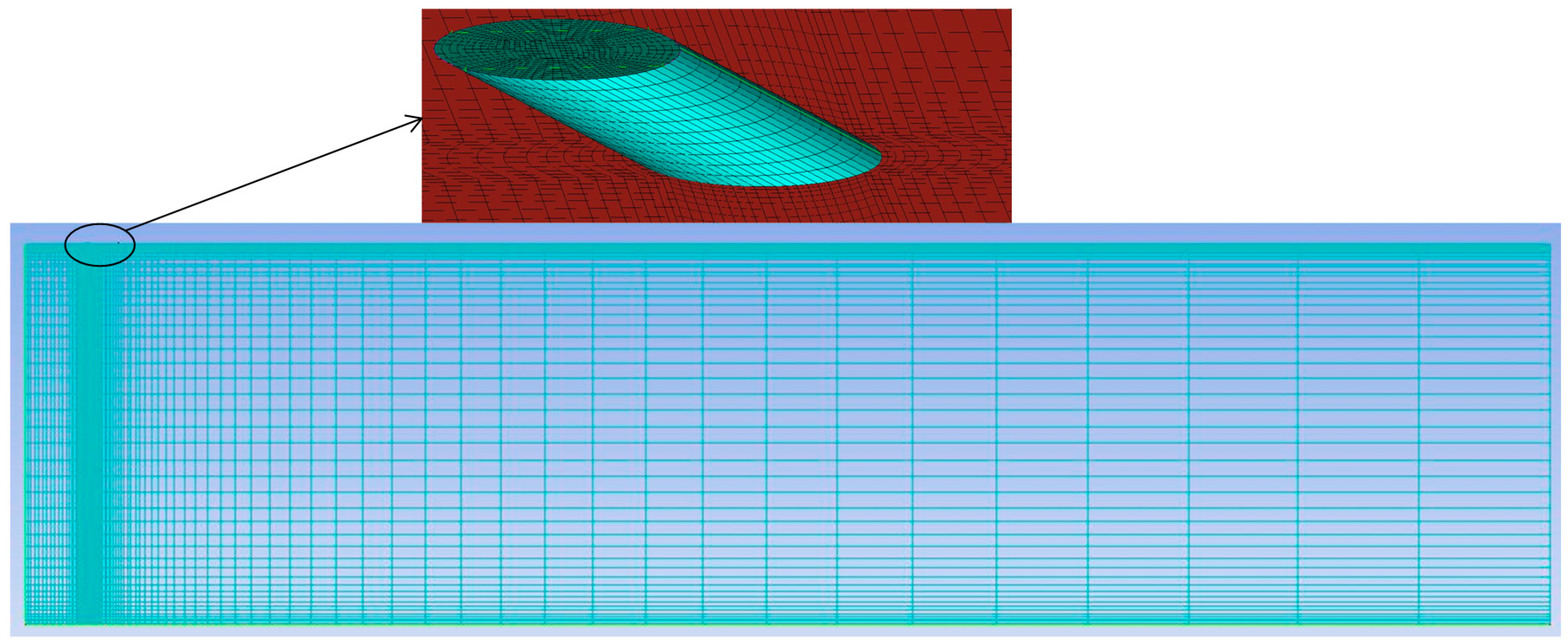
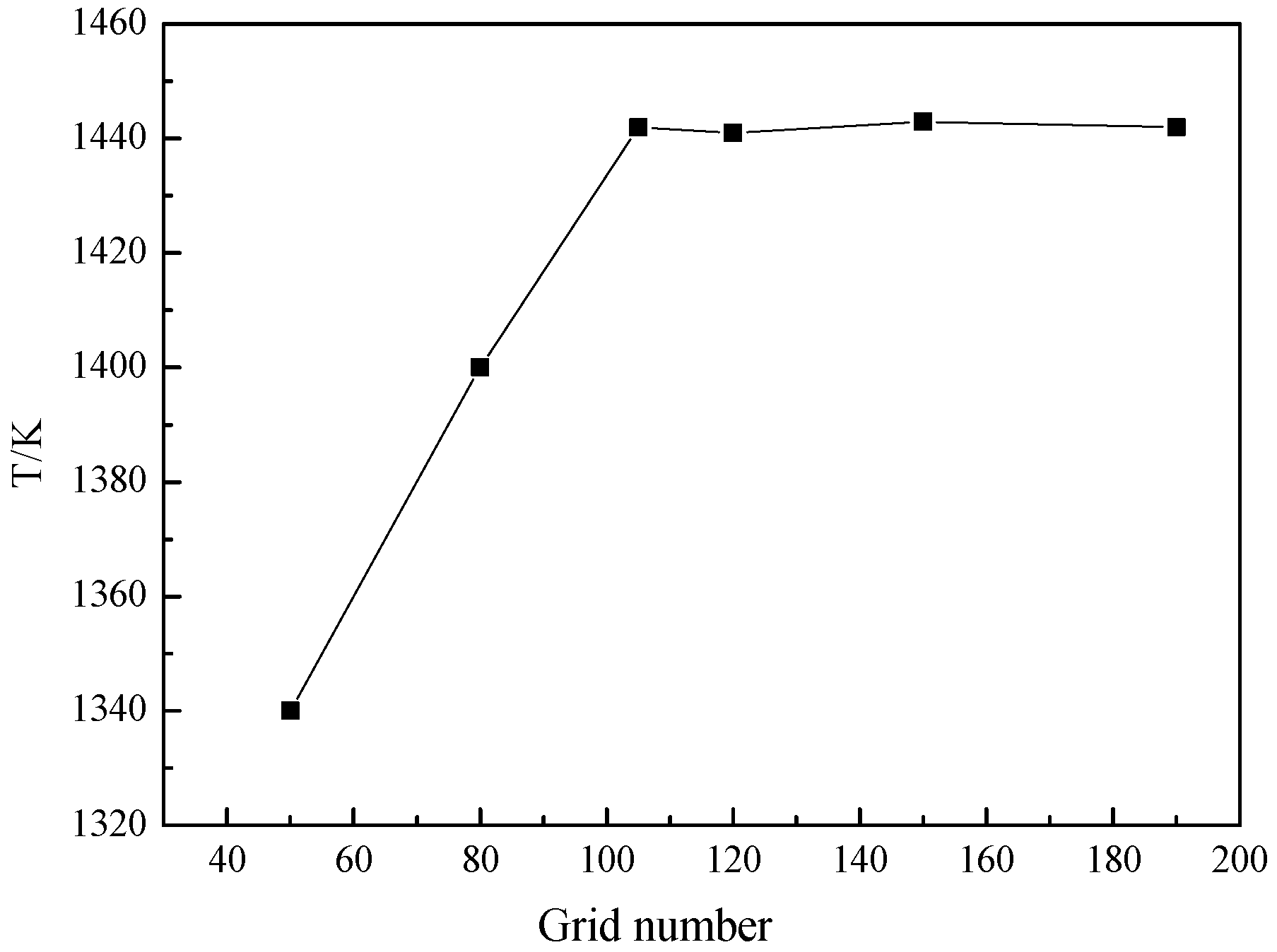
We adopted the software ICEM in the division of the grids. Overall, we established a structured grid, whereas in the vicinity of the cooling holes and wall surface, grids are densified. The thickness of the first layer amounts to 0.05 mm, and thereafter the grid spacing of each layer increases by a ratio of 1.1, as shown in Figure 4. In addition, we verified the independence of the grids with numbers of 500,000, 800,000, 1.05 million, 1.2 million, 1.5 million, and 1.9 million, respectively. When the number of grids exceeds 1.05 million, the computational results are consistent under different grid numbers, as shown in Figure 5. In this paper, we conducted the research based on 1.5 million grids after taking into holistic factors. Figure 6 illustrates the comparisons between experimental results and numerical calculation results.
5. Computational Method
We used the commercial CFD software FLUENT during the numerical solution. The solver used is an implicit solver; the discrete formats are all second-order differences, and the SIMPLE algorithm was adopted during the pressure and velocity coupling. The criteria for solving convergence include the following: The accuracy of each residual is less than 10−5; the residual curve tends to be flat; and the wall temperature tends to be stable.
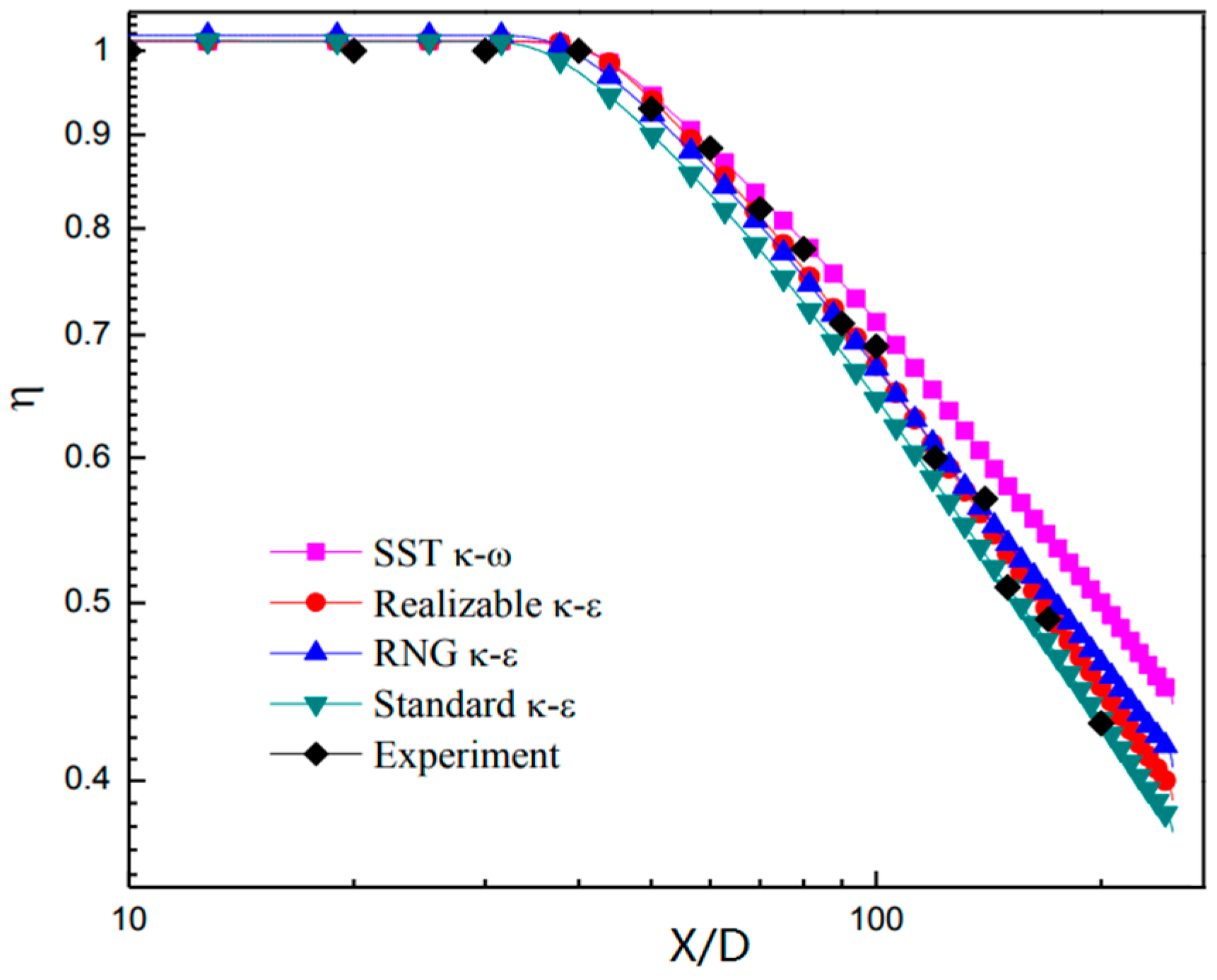
Given that the realizable k-ε turbulence model takes into account the effect of average rotation when defining the turbulent viscosity, the model features optimal simulation capabilities for jets, mixed flows, boundary layers, and flows with separation. In this paper, we intend to adopt the realizable k-ε turbulence model. This computational method is the same as that used in literature [12,13], and it was verified by experiments.
6. Results and Analysis
6.1. Wall Cooling Efficiency and Wall Temperature Distribution
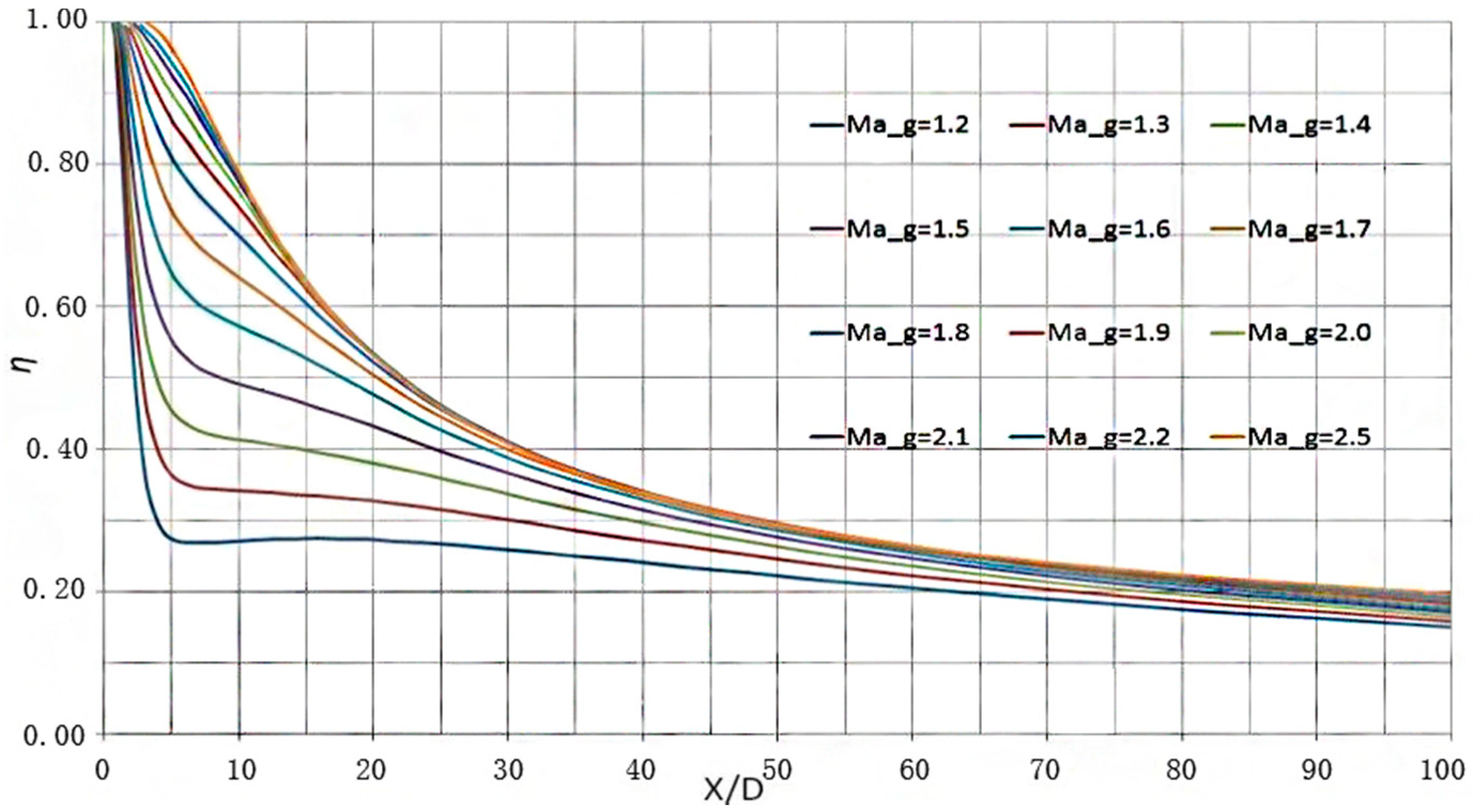
Figure 7 illustrates the distribution of cooling efficiency along the flow direction on the center line downstream of the hole. When the Mach number of the main flow (Ma_g) is smaller than 1.2, the cooling efficiency would decrease at a rapid velocity along the flow direction, which would slow down after X/D = 5. The cooling efficiency distribution curves on the center line keep a similar profile as Ma_g increases, whereas the magnitude of cooling efficiency increases slightly.
6.2. Longitudinal Cross-Section Flow Field at Incident Position
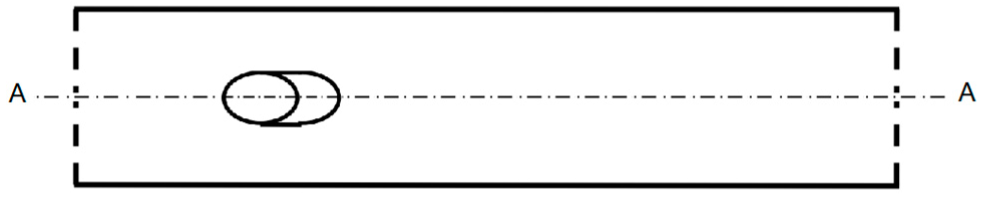
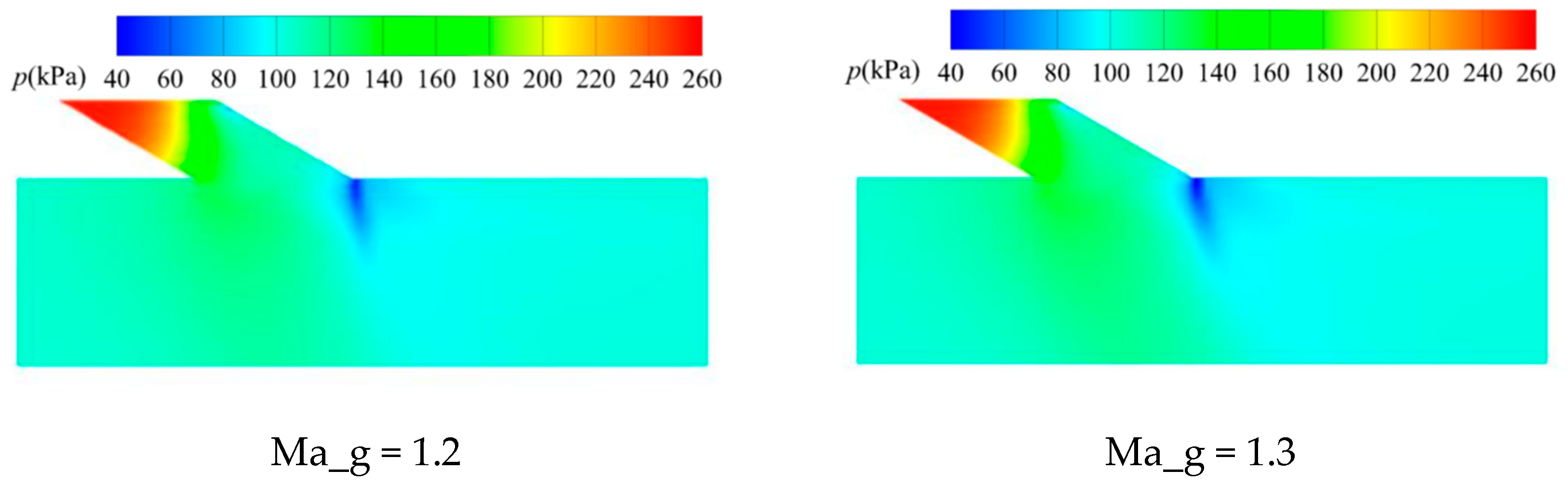
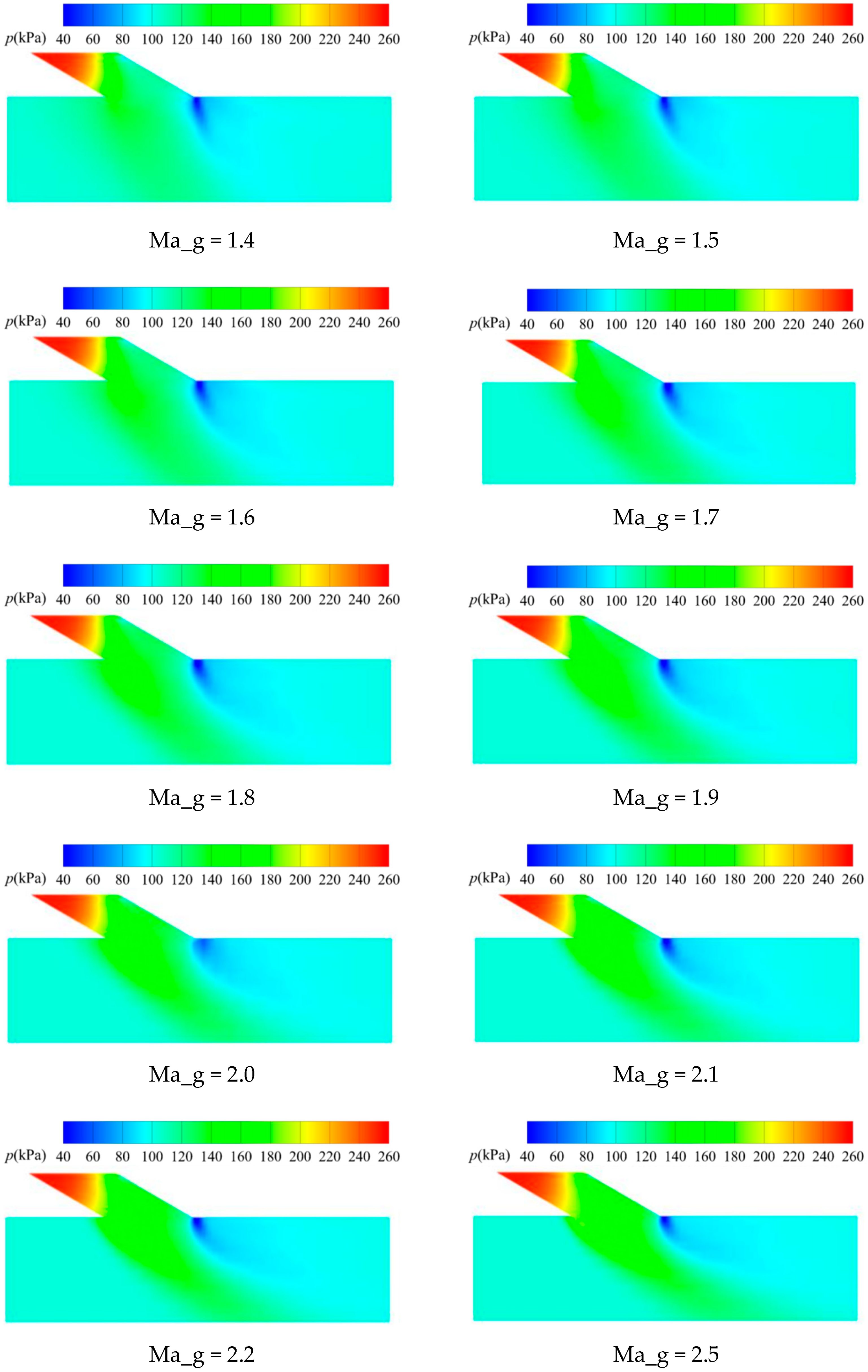
When the outflow of the film hole is injected into the supersonic main flow, the upstream of the hole in the main flow channel would form an obstacle to the supersonic main flow and induce a bow-shaped oblique shock wave. The flow state of the main flow in front of the wave would remain stable. When the main flow passes through the oblique shock wave in front of the hole, the velocity would decrease, and the pressure would increase. Figure 8 illustrates a schematic view of the position of the longitudinal section AA near the hole exit. Figure 9 illustrates the static pressure distribution of the AA section. As shown by these figures, at the hole exit, a high-pressure area emerges directly below the incident position of the film jet, which is expanded with the intensity of oblique shock in front of the hole due to the increase of Ma_g.
In addition, the film jet caused a low-pressure area downstream at the hole exit, whose area shrunk as Ma_g increased. Driven by the main flow, the low-pressure zone slopes downstream.
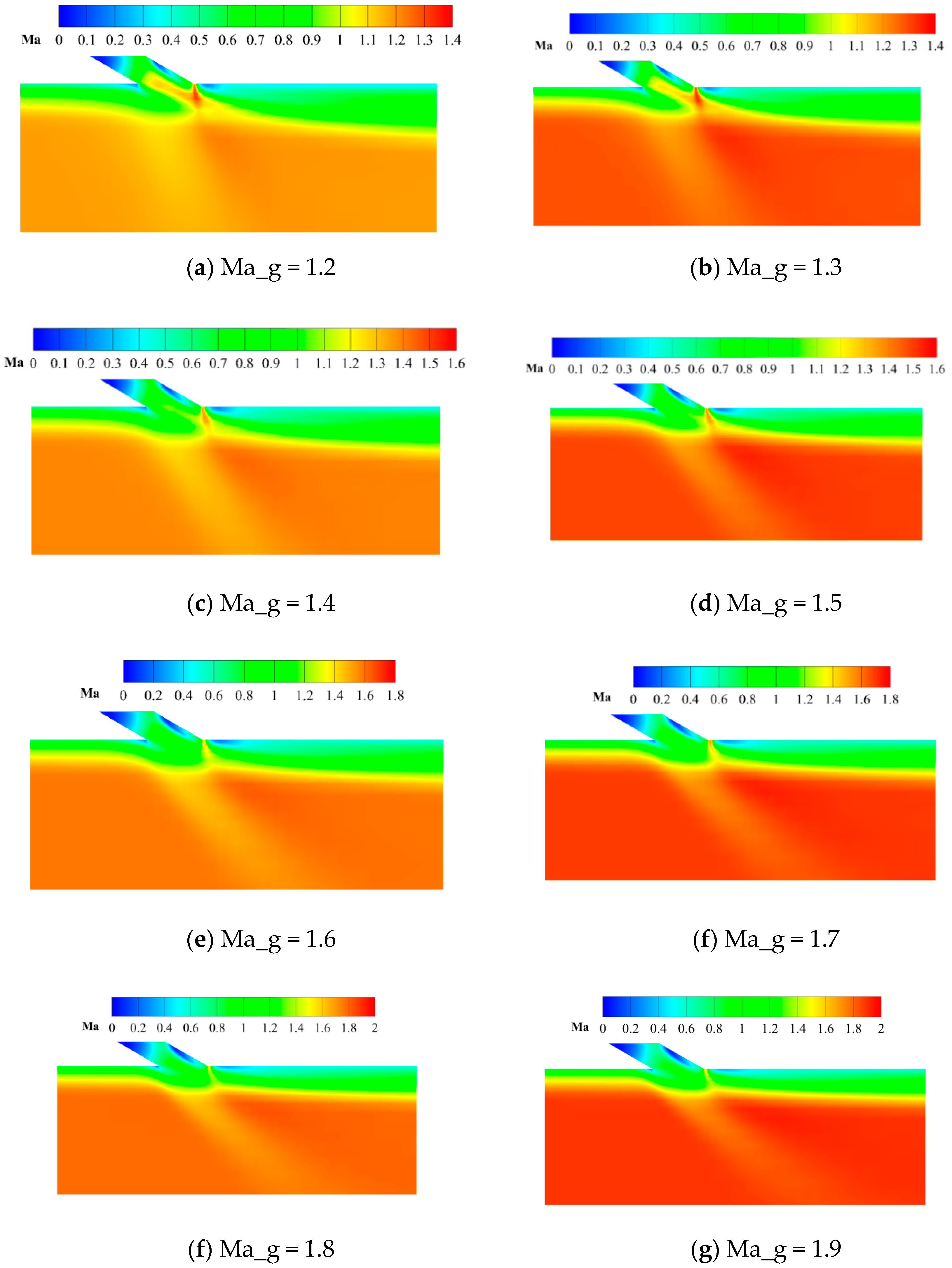
The oblique shock wave in front of the hole acts on the boundary layer of the wall, leading to the increase of pressure and an adverse pressure gradient near the wall while causing the cooling film layer to be detached from the wall. Figure 10 illustrates the effects imposed by the injection of cooling film to the distribution of Mach number in the main flow on the central longitudinal section, and then reveals the impact of Ma_g. The boundary layer is lifted under the action of the film jet, and the expansion wave that obstructs the main flow emerges in the vicinity of the rear of the hole. Under the influence of the film, a low-pressure separation zone appears at the leading and trailing region of the hole exit separately. It can be seen that as Ma_g increases, the protrusion caused by the boundary layer becomes slightly smaller. Furthermore, the main flow velocity gradually declines behind the shock wave, and there is a weak disturbance of the film jet to the main flow. In addition, the intensity of the expansion waves at the hole exit gradually decreases, and the two low-pressure areas in the front or rear of the hole grow smaller, leading to the enhanced adhesion of the flow wall in the downstream of the hole.
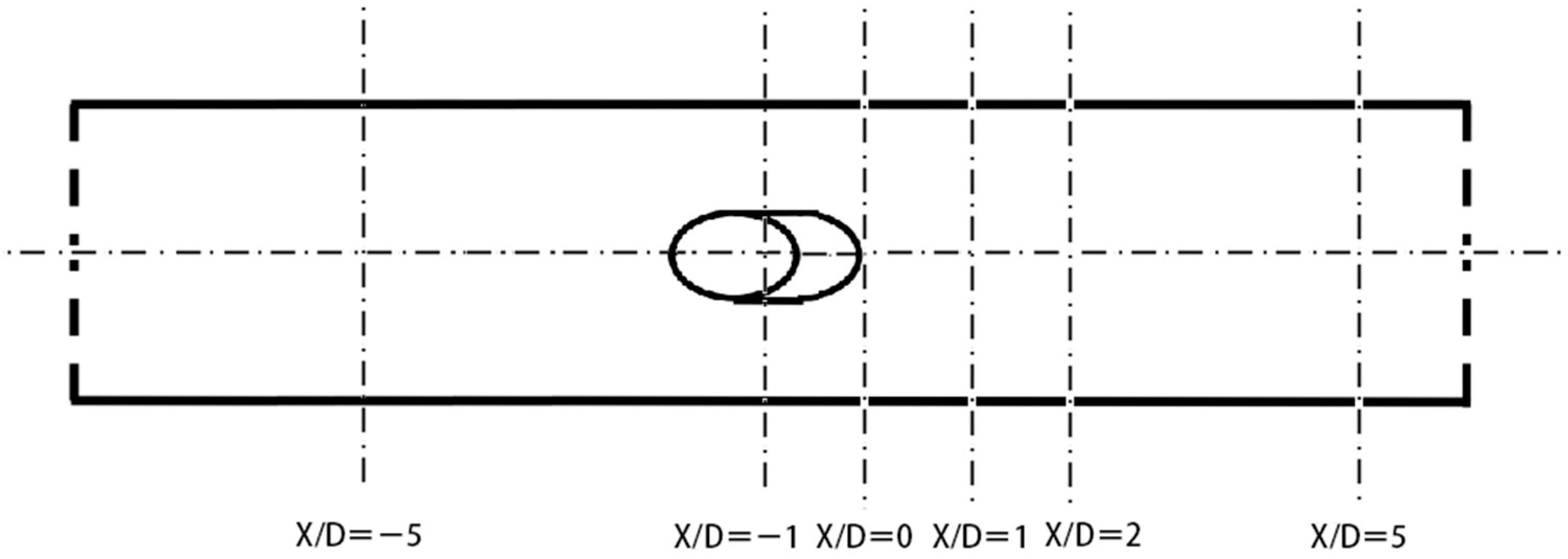
6.3. Vortices Distribution in the Cross Section Downstream
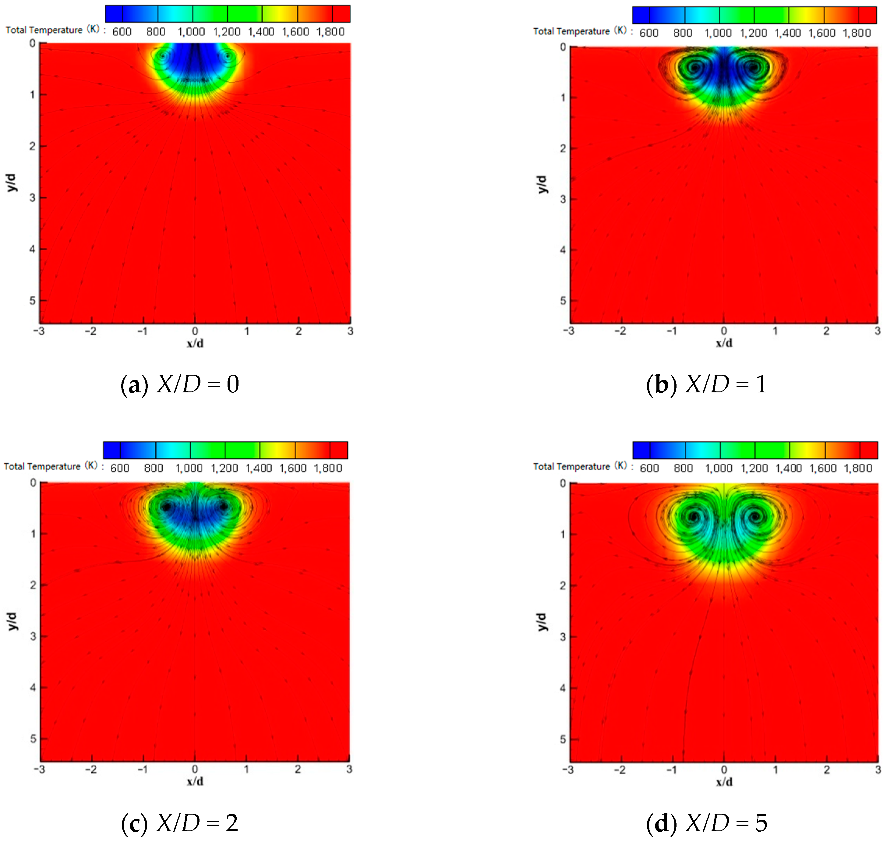
The cross-sectional positions are shown in Figure 11. Figure 12 illustrates the streamline diagrams of the temperature and velocity of different cross sections downstream at the hole exit when the film jet pressure amounts to 0.25 MPa and Ma_g amounts to 1.2. Not far away from the downstream of the exit of the hole, a pair of reverse kidney-shaped vortices generate the gas outflow on both sides and continue their downstream development. Under the action of the vortex, the film flow is gradually mixed with the main flow. As shown by the figure, with the downstream development, the film continues to transfer a high-temperature main flow to the wall. Consequently, the film is lifted away from the wall, and the cooling efficiency in the downstream becomes lower, which is similar to the situation under subsonic conditions.
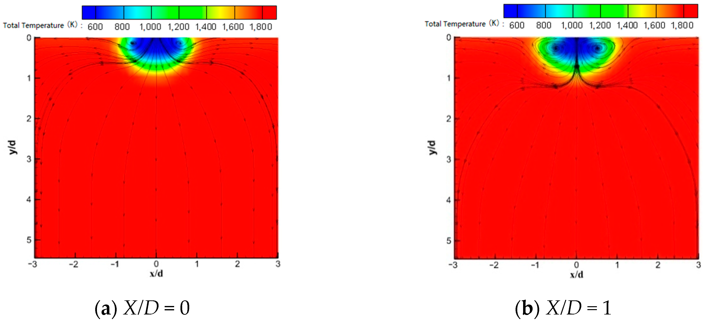
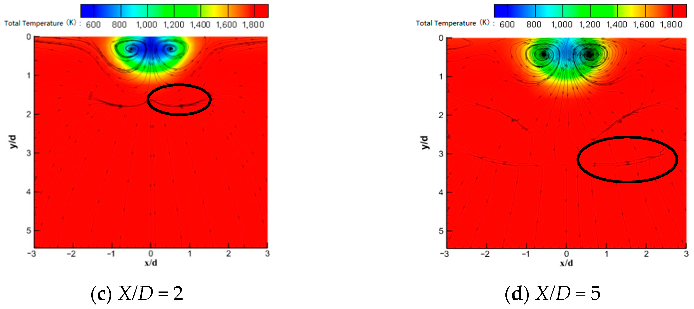
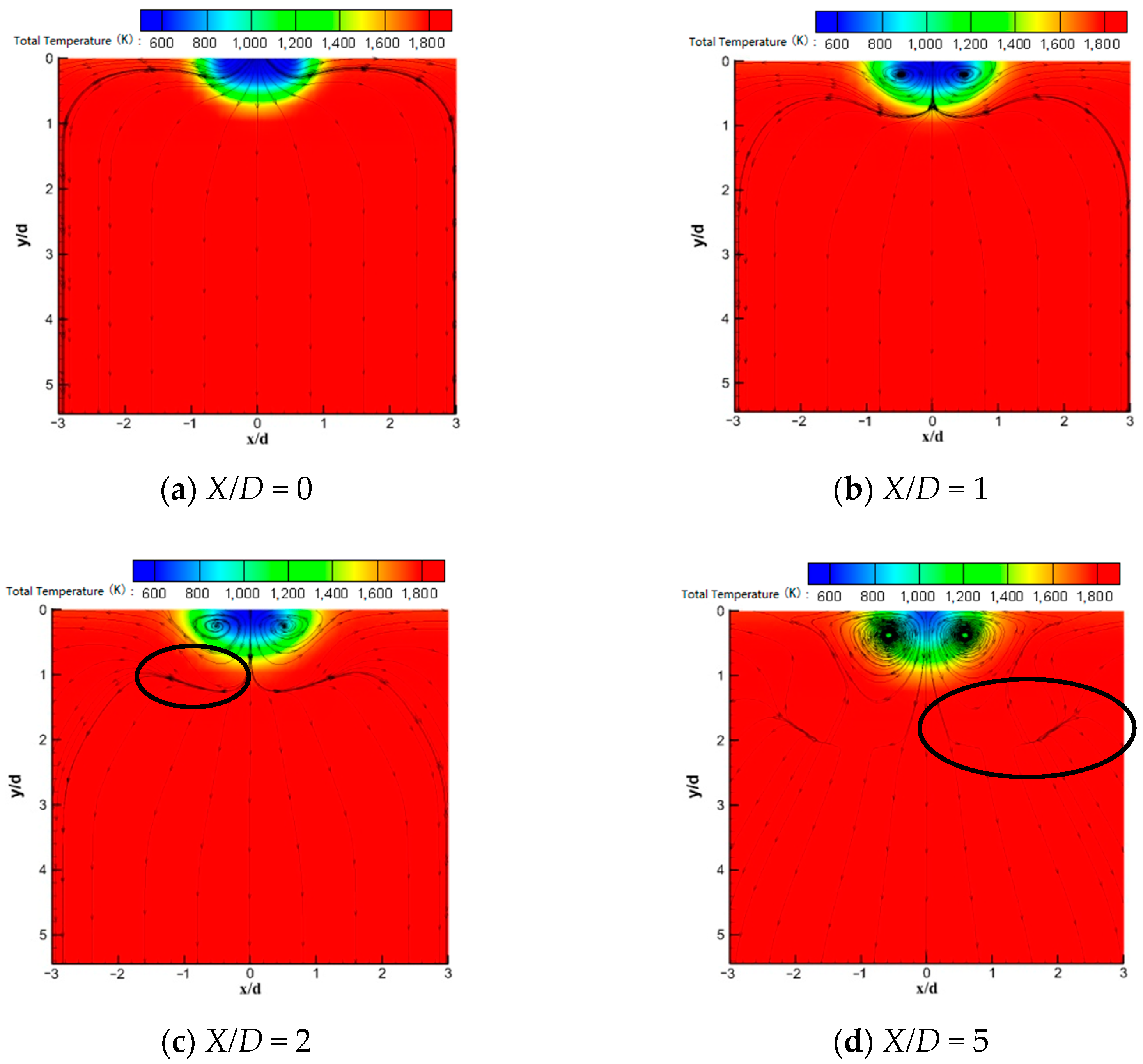
Figure 13 and Figure 14 illustrate the temperature and streamline distribution of different cross sections in the downstream of the hole exit when the film jet pressure amounts to 0.25 MPa, and the main flow Mach numbers are 1.8 and 2.5, respectively. The distribution is similar to that in Figure 12. From the results shown later, we could note that when Ma_g amounts to 1.8 and gradually increases, the depth of the film jet penetrating the main flow gradually becomes shallower. Under the effects of suppression by the main flow, the vortex downstream of the film exit hole is closer to the wall surface, and the adherence is significantly enhanced for the low-temperature cooling flow. When Ma_g increases to 2.5, even under the continuous action of the kidney-shaped vortex, the cold flow low-temperature area is still suppressed on the wall surface, and an effective film can still be formed to protect the high-temperature wall surface in the far downstream.
It should be noted that in Figure 13c,d, on the X/D = 2 and X/D = 5 sections, there is a clear boundary of mixing between the film outflow and the main flow, which differs from the subsonic conditions. At the line of the mixing boundary, the streamline scatters to both sides, pointing to the main core area and the film jet wall surface, respectively. In other words, the streamline source term appears, and flow stratification takes place. A similar distribution appears in Figure 14c,d. These cross sections all depict the environment with a large Ma_g, considering that when Ma_g is small and when subsonic flow takes place, the flow would not exist. Judging from our analysis, this phenomenon may be derived from the impact of the strong shock waves generated in the main flow channel when Ma_g is large.
6.4. Phenomenon of Stratified Flow of the Main Flow in Hypersonic Speed
6.4.1. Changes of the Stratified Flow Phenomenon along the Streamwise Flow
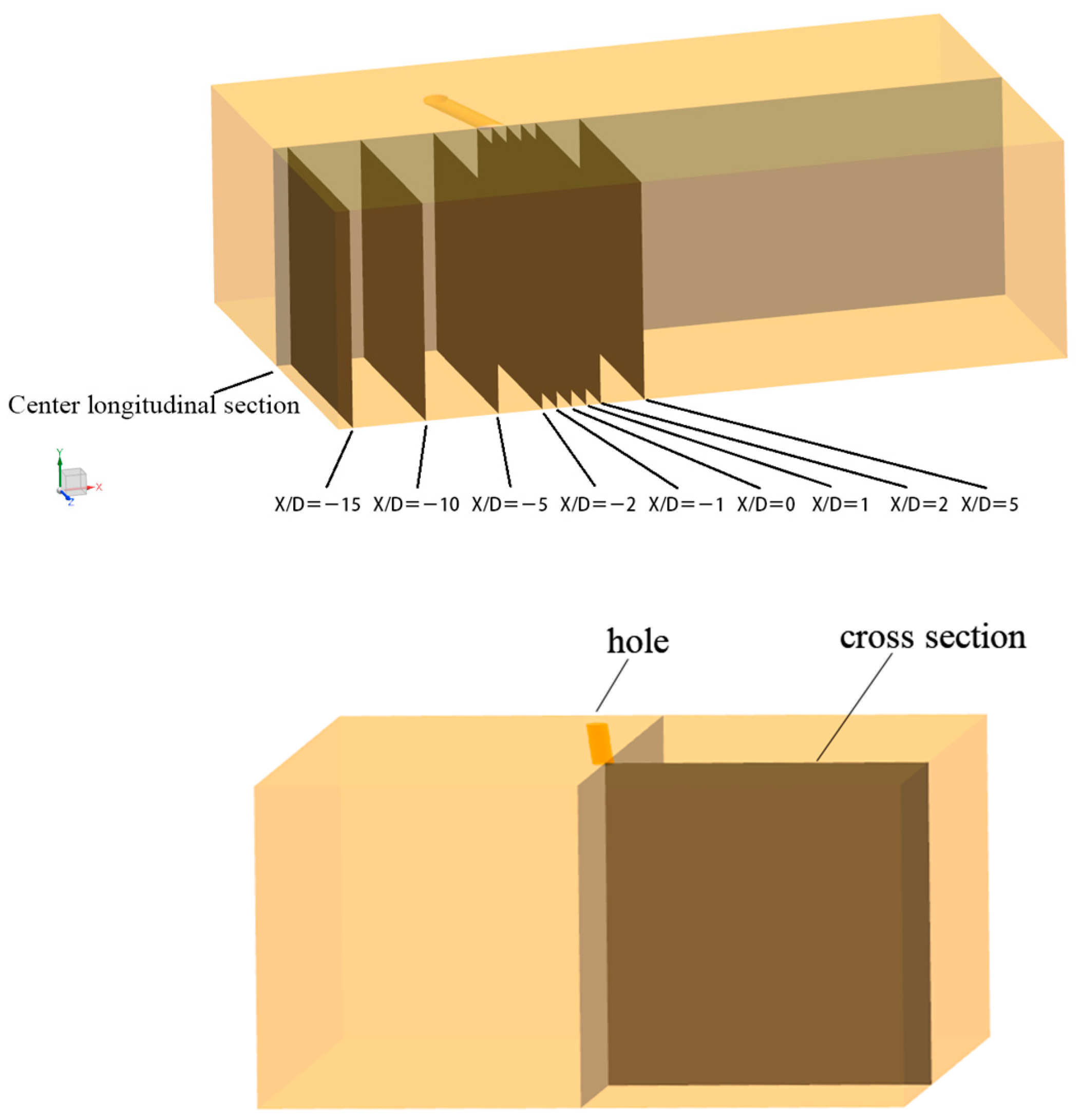
In this section, we elaborate on the changes of the stratified flow phenomenon in different cross sections along the streamwise flow and the cross sections of varying sorts are shown in Figure 15.
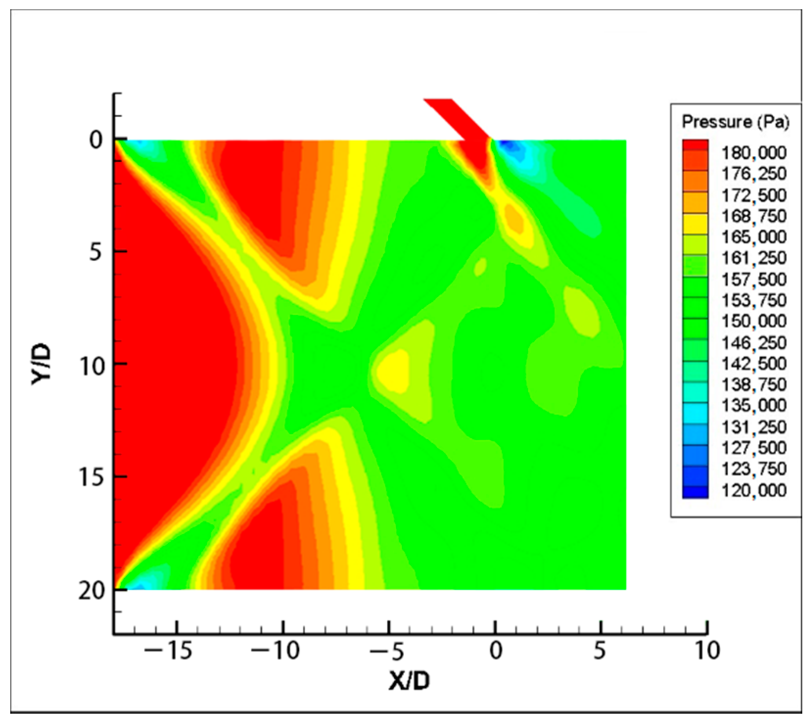
Figure 16 illustrates the distribution of the pressure on the central longitudinal section of the through hole at the main flow Mach number of 1.8. On the upper and lower walls of the entrance, we could note that a wave system is generated, which is transmitted to and intersects with the downstream. The wave system is composed of an expansion wave fan and compression wave, and a low pressure area is formed inside the wave system.
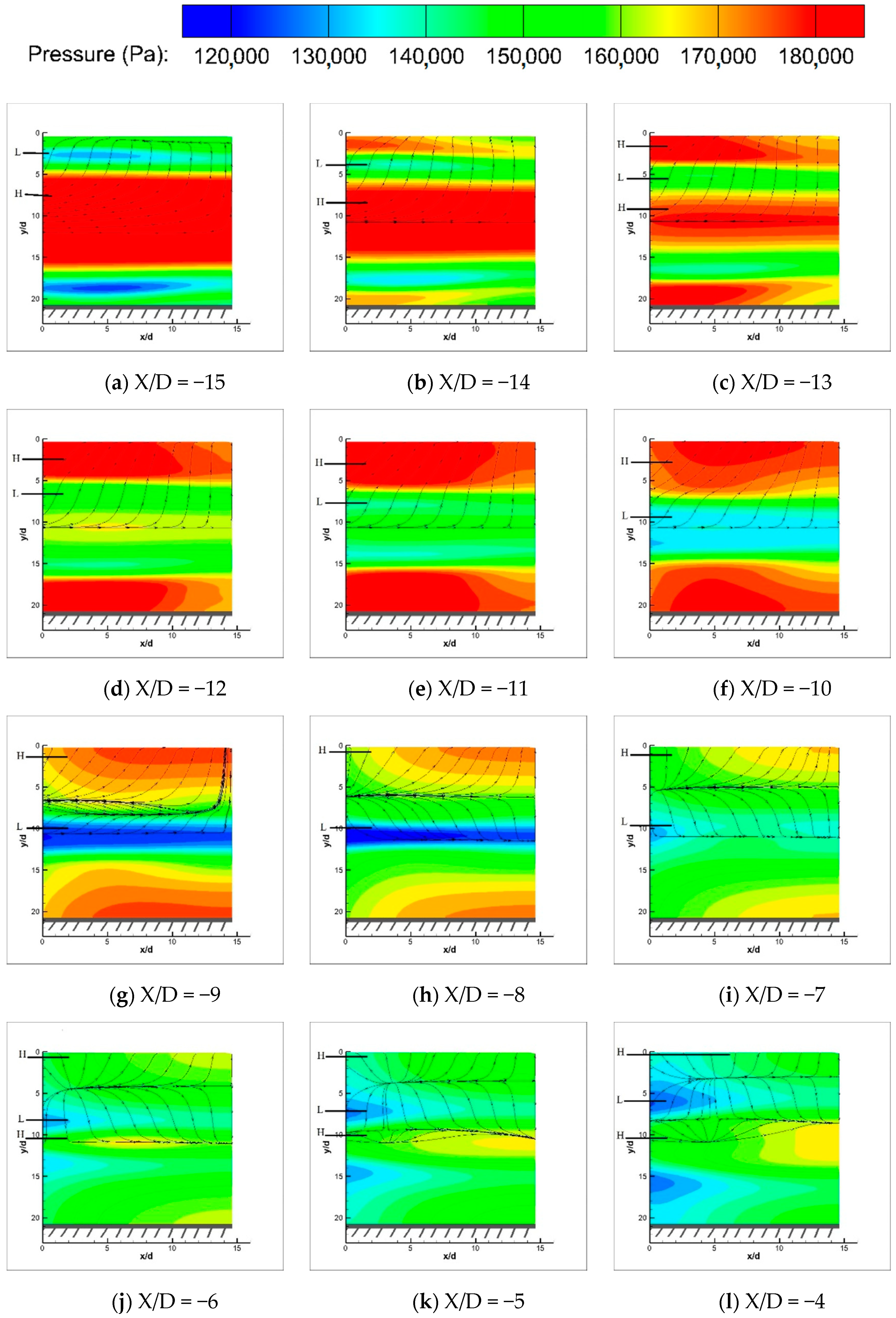
Figure 17 illustrates the pressure and the streamline distribution on sections between X/D = −15 and X/D = 0 when the main flow Mach number amounts to 1.8. Given that the two sides of the hole are symmetrical to each other, only the flow field on one side is shown in Figure 17. The positions of the cross sections are shown in Figure 15.
At the X/D = −15 section, the wave system and the low-pressure region (shown as position L in Figure 17) commence near the wall, whereas the high-pressure region is located in the center of the flow channel (shown as position H in Figure 17). The fluid flows from the center of the flow channel to the wall as the streamlines illustrate.
In the range between X/D = −15 and X/D = −8, the position of the wave system and low-pressure region moves from the wall to the center. As the axial position changes during the movement, the difference is gradually diminished between high and low pressure areas. In the X/D = −10 section, the high and low pressure areas are mixed with each other, and the streamline fluctuates, indicating that the flow direction changes in a zigzag manner. At X/D = −9 and X/D = −8 cross section, the high and low pressure areas are vigorously mixed with each other, and the local fluid appears to reverse flow, leading to the gradual formation of a forward-pressure flow and two well-defined stratified fluids.
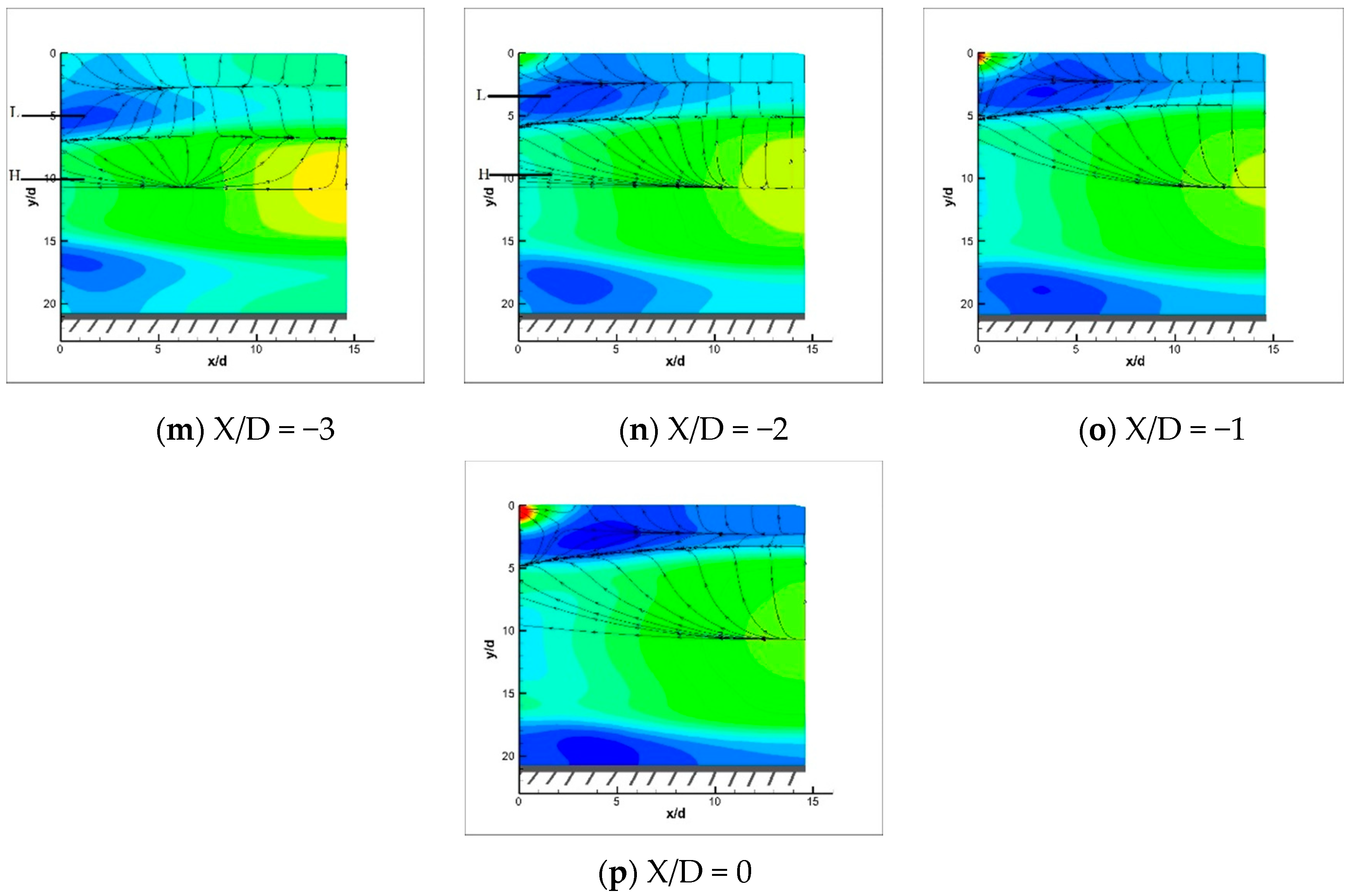
In the range between X/D = −8 and X/D = 0, the influence imposed by the wave system at the opposite side on the flow gradually increases as the fluid flows further downstream, and the low pressure area moves with the wave system from the center to the wall surface accordingly. During the movement, the high-pressure area on the wall is gradually diminished, whereas the pressure interface moves toward the wall, which is shown by the corresponding movement of the streamline boundary surface. In the X/D = −6 and X/D = −5 sections, a new high-pressure area appears in the center of the flow channel, and the counter-pressure flow in the vicinity of the center becomes unstable. As a result, a new co-pressure flow layer is formed with an interface of the streamline intersection. As X/D continues to change from −5 to −1, the wave system moves towards the wall, and the high-pressure area in the center of the flow channel is gradually expanded; the interface of the streamline intersection gradually moves towards the wall accordingly, and the distance from the dispersed boundary surface is gradually diminished.
When X/D = 0, the wave system moves to the wall surface; the high-pressure area adjacent to the wall completely disappears and is replaced by the low-pressure area. In addition, the two streamline interfaces merge with each other, and the second layer of fluid is broken down by the upper and lower layers of fluid before being merged into a forward pressure gradient fluid from the center to the wall. This is similar to the initial state of X/D = −15.
Based on the above analysis, there is always a flow tendency in the vicinity of the wall area and in the center of the flow channel towards the wall, whose direction is opposite to the diffusion trend of cold air into the main flow. This trend weakens the deepening and blending of the cold air into the main flow in effect, which is conducive to the adherence of the film jet.
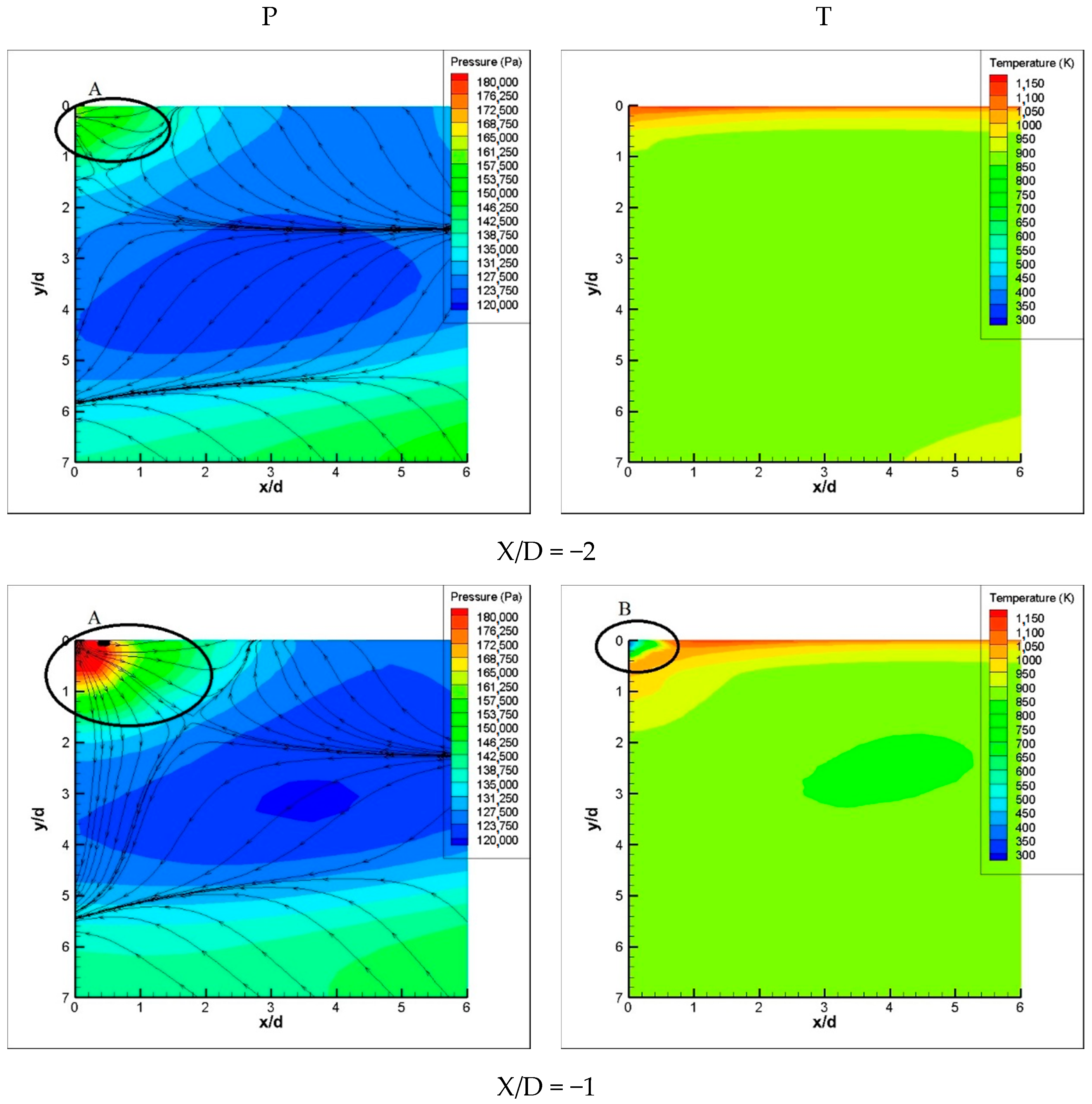
In addition, it can be noted that in the X/D = −1 and X/D = 0 sections, the flow in the upper left corner of the figure slightly differs from the above layering, which is driven by the high-pressure outflow of the cooling holes. Figure 18 illustrates the pressure contours and temperature contours on the cross section near the location of the film jet outflow.
When X/D = −2, the cross section is located in front of the cooling hole, and no film jet passes through this cross section. In addition, it can be noted from the temperature contour map that no low-temperature fluid flows through this section. However, a high-pressure area can evidently be seen in the pressure contour map, which is the high-pressure area formed due to the bow-shaped oblique shock wave in front of the aforementioned hole.
When X/D = −1, the cross section passes through the middle of the cooling hole, and the area of the high-pressure area A gradually expands. At this moment, a small cold flow passes through the area.
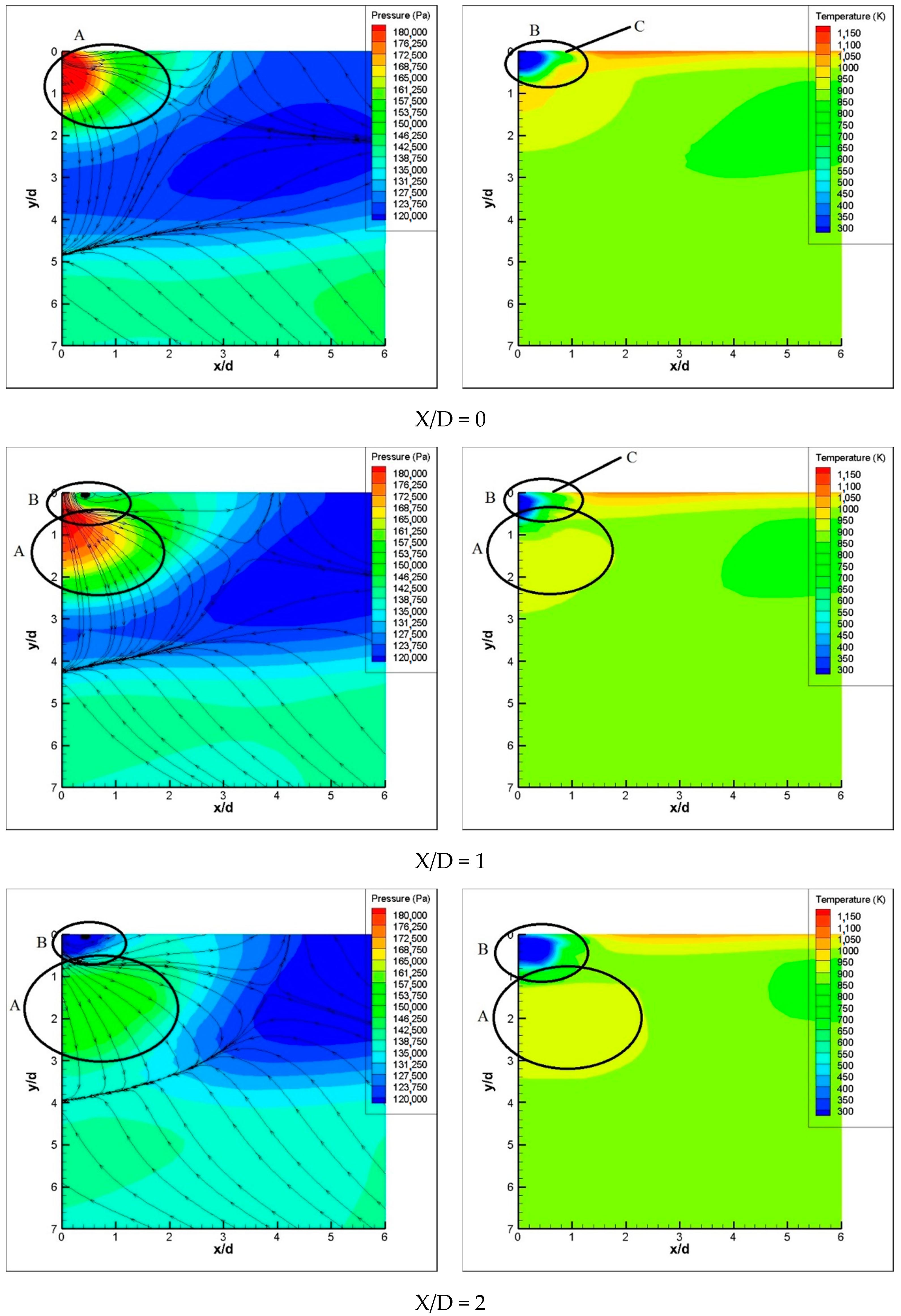
When X/D = 0, the cross section is located in the downstream of the exit of the cooling hole. As shown in the temperature contour map, the low temperature area B constitutes the outflow of the small hole. The film jet diffuses in the x-direction, as shown at position C in the figure, and the diffusion in the y direction is weaker since it is suppressed by the high-pressure area A. Under the influence of the three-dimensional oblique shock wave in front of the hole, the high-pressure area in the upstream of the hole and adjacent to the hole exit is enveloped. Consequently, the film jet is forced to divert from the hole after it flows out, and continues its downstream flow along the wall.
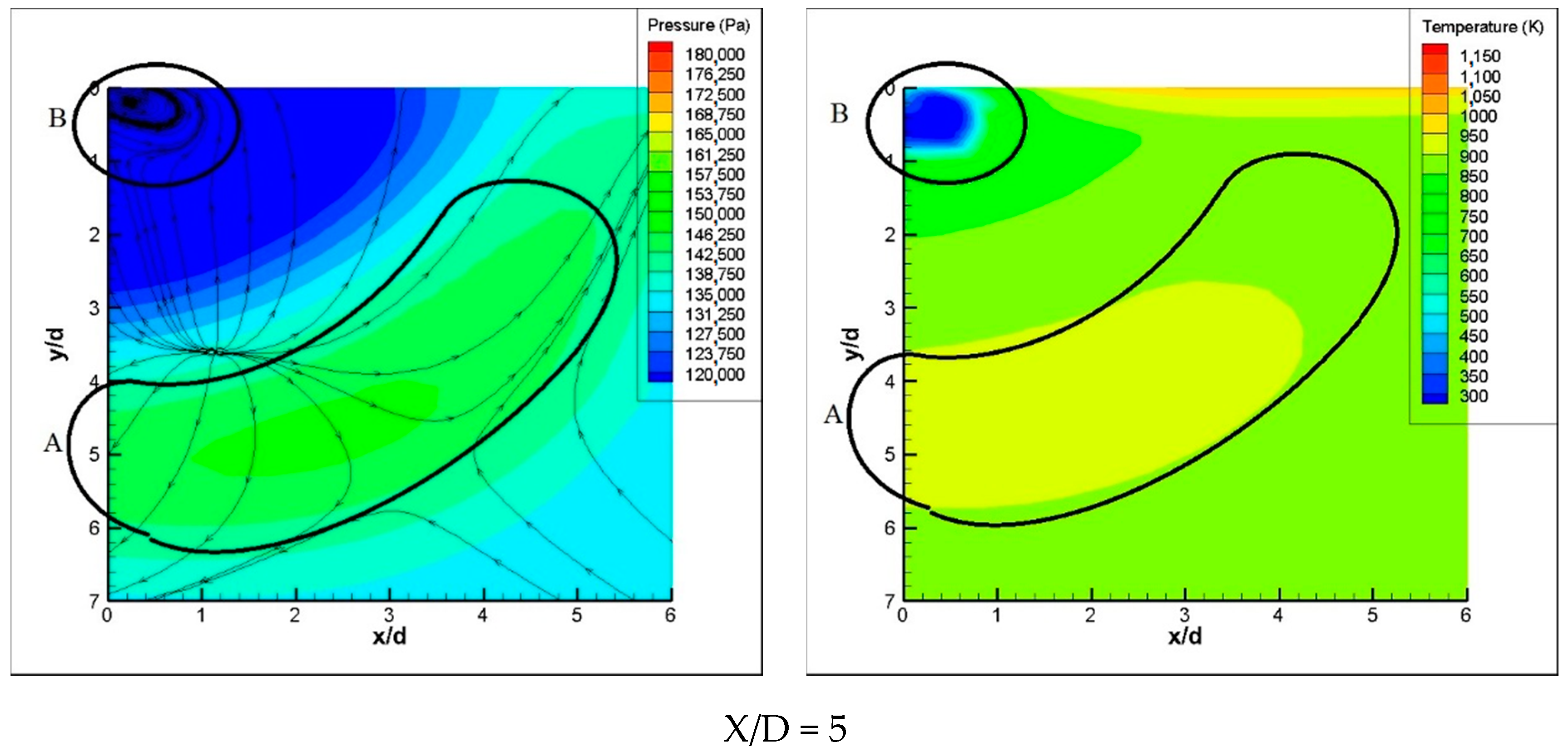
When X/D = 1 or 2, it can be noted that the high-pressure area A begins to be detached from the wall surface, but it still surrounds and presses the film jet stream near the wall surface. In the meantime, the flow continues to develop downstream, and when X/D = 5, the shock wave and high-pressure area A are away from the wall surface. Driven by the pressure of the high-pressure area, the fluid flows from the high-pressure area to the wall surface. As a result, the film jet continues to flow near the wall surface.
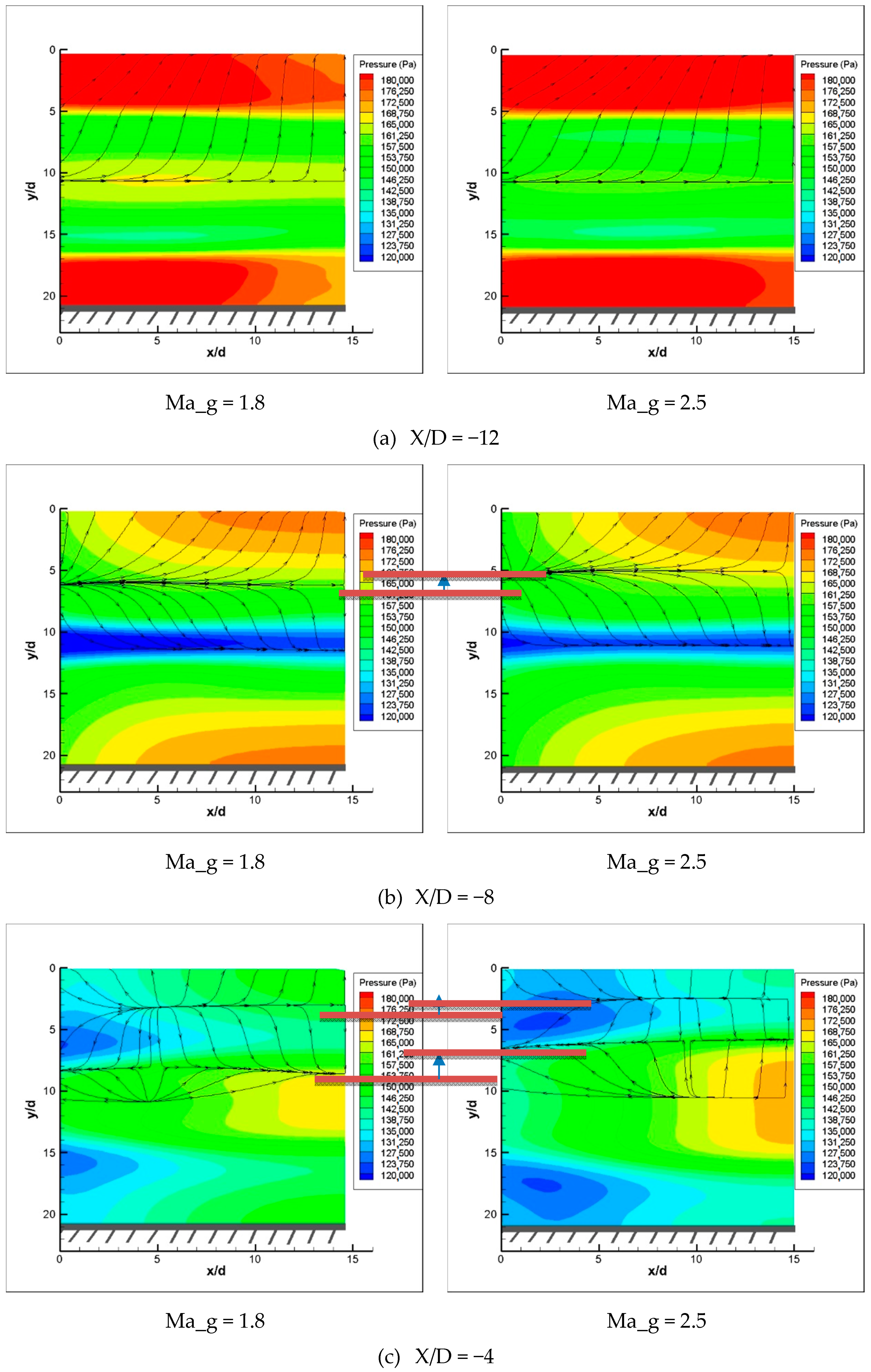
6.4.2. Changes of the Stratified Flow Phenomenon with Ma_g
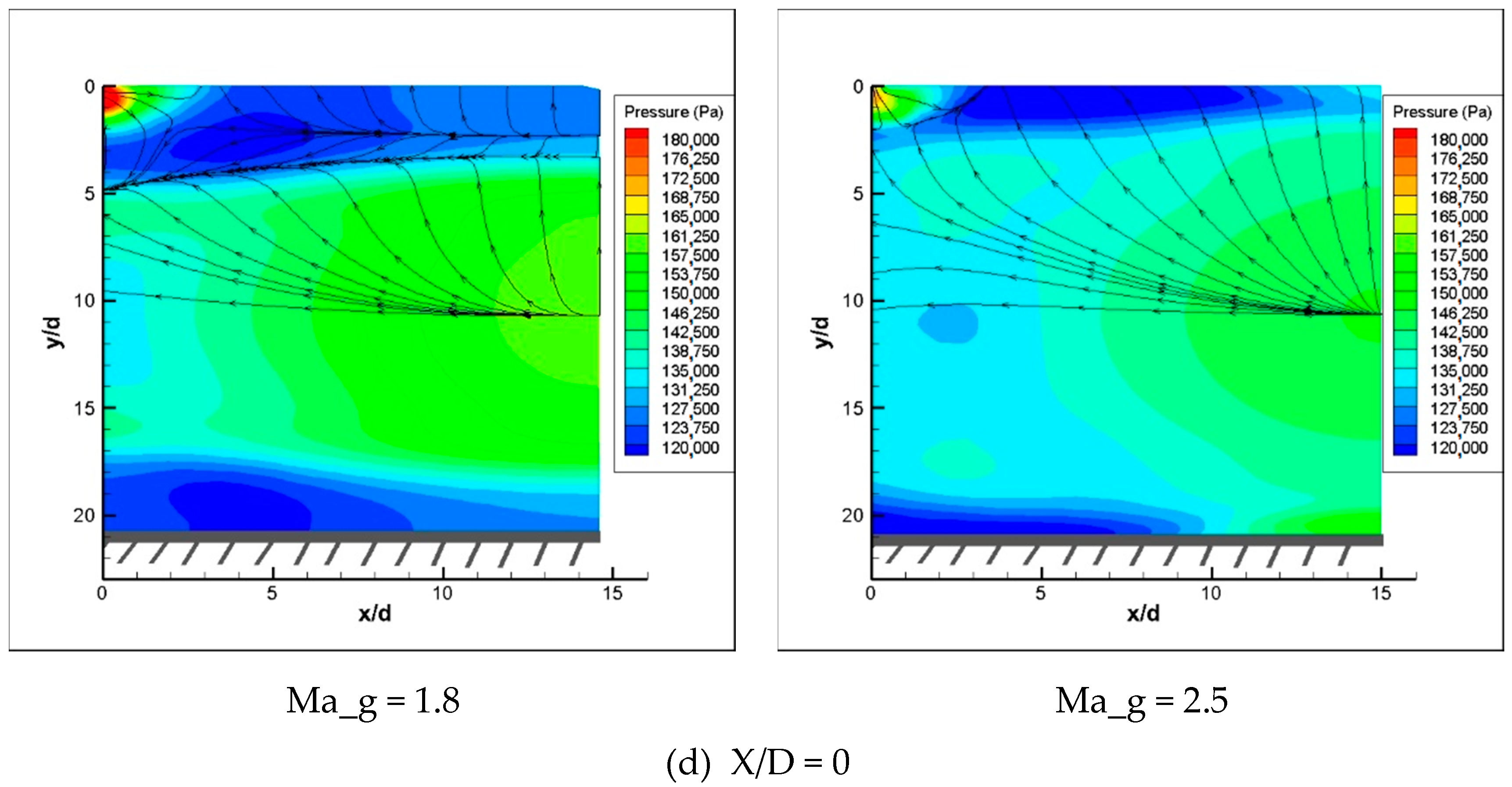
Figure 19 shows the streamline and pressure contours of the cross section along the same position at different main flow Mach numbers. It can be noted that the stratified flow phenomenon when Ma_g is different is basically similar. At the same cross-sectional position, when Ma_g is larger, the inlet wave system is stronger, and the fluid stratification boundary surface is closer to the wall surface than when Ma_g is smaller (as shown by the horizontal line in the figure), which is consistent with the rule shown in Figure 11c,d and Figure 12c,d above.
It is worth mentioning that when Ma_g increases, the oblique shock wave in front of the hole becomes stronger. In addition, the high-pressure area brought by the oblique shock wave in front of the hole is more capable of suppressing the film jet, which can better keep the film jet close to the wall.
7. Conclusions
In this paper, we carried out a numerical simulation on film cooling in a supersonic environment. Under different inlet Mach numbers, we carried out numerical simulations of the interaction between shock wave and the main flow and film jet. The influence of shock wave on the cooling film is obtained, and the flow and heat transfer distribution of the film jet are revealed under the supersonic main stream environment. The main results can be concluded as the following:
- (1)
- Under supersonic main stream conditions, the increasing of Ma_g always causes the film jet to main flow ratio to decrease. The relatively small amount of film jet weakens its mixing with the main flow, leading to a better attachment of the film.
- (2)
- Multi-interfacial layered structures were formed as the film jet flew across shock waves. At the interfaces of the film jet and shock waves, additional pressure was exerted on the film towards the wall. The pressure increased as the Mach number of main flow increased; this contributed to the increased adhesion of the gas film, which caused the cooling enhancement under supersonic condition.
- (3)
- In the vicinity of the film hole exit, a local low pressure region was formed under the influence of the supersonic main flow. An aerodynamic convergent–divergent state was formed in the film hole, devastating the state of supersonic congestion of the film hole and further enhancing the film cooling effect.
Author Contributions
Introduction, B.Z. and J.-Q.L.; Physical Model, B.Z., J.-Q.L. and Z.-g.W.; Division of Grids and Verification of Grid Independence, Z.-g.W. and Y.-X.C.; Results and Analysis, B.Z. and Z.-g.W.; Section 6.2, Section 6.3 and Section 6.4, Z.-g.W., Y.-X.C., J.-Q.L. and H.-h.J. All authors have read and agreed to the published version of the manuscript.
Funding
This research was funded by National Science and Technology Major Project (2017-Ⅰ-0001-0001).
Institutional Review Board Statement
Not applicable.
Informed Consent Statement
All the authors who participated in the paper signed the consent form. The use of all data is under approve.
Data Availability Statement
Some or all data, models, or code generated or used during the study are available from the corresponding author by request.
Conflicts of Interest
The authors declare no conflict of interest.
References
- Hartnett, J.P.; Birkebak, R.C.; Eckert, E.R.G. Velocity distributions, temperature distributions effectiveness and heat transfer in cooling of a surface with a pressure gradient. Int. Dev. Heat Transf. 1961, 682–689. [Google Scholar] [CrossRef]
- Bergeles, G.; Gosman, A.D.; Launder, B.E. Double-row discrete holes cooling: An experimental and numerical study. ASME J. Eng. Power 1980, 102, 498–503. [Google Scholar] [CrossRef]
- Bons, J.P.; Macarthur, C.D.; Rivir, R.B. The effect of high freestream turbulence on film cooling effectiveness. ASME J. Turbo Mach. 1996, 118, 814–825. [Google Scholar] [CrossRef]
- Jiang, P.X.; Wang, B.X.; Luo, D.A.; Ren, Z.P. Fluid flow and convective heat transfer in a vertical porous annulus. Numer. Heat Transf. 1996, 30, 305–320. [Google Scholar] [CrossRef]
- Goldfield, M.L.; Sargison, J.E. A converging slot-hole file-cooling geometry-part 2: Transonic nozzle guide vane heat transfer and loss. ASME J. Turbo-Mach. 2002, 124, 461–471. [Google Scholar]
- Rozati, A.; Danesh, K.T. Effect of coolant-mainstream blowing ratio on leading edge film cooling flow and heat transfer-LES investigation. Int. J. Heat Fluid Flow 2008, 120, 857–873. [Google Scholar] [CrossRef]
- Zhang, J.Z.; Xie, H.; Yang, C.F. Numerical study of flow and heat transfer characteristics of impingement/effusion cooling. Chin. J. Aeronaut. 2009, 22, 343–348. [Google Scholar]
- Vos, R.; Farokhi, S. Airfoil Aerodynamics. In Introduction to Transonic Aerodynamics; Springer: Dordrecht, The Netherlands, 2015; Volume 110, pp. 367–425. Available online: http://dl.samegp.com/Digital_Liblary/Transonic%20Flow/(Fluid%20Mechanics%20and%20Its%20Applications%20110)%20Roelof%20Vos,%20Saeed%20Farokhi%20(auth.)%20-%20Introduction%20to%20Transonic%20Aerodynamics-Springer%20Netherlands%20(2015).pdf (accessed on 9 December 2020).
- Seddon, J. The Flow Produced by Interaction of a Turbulent Boundary Layer with a Normal Shock Wave of Strength Sufficient to Cause Separation; Her Majesty’s Stationery Office: London, UK, 1967. [Google Scholar]
- Matsuo, K.; Miyazato, Y.; Kim, H.D. Shock train and Pseudo-shock phenomena in internal gas flows. Prog. Aerosp. Sci. 1999, 35, 33–100. [Google Scholar] [CrossRef]
- Pirozzoli, S.; Bernardini, M.; Grasso, F. Direct numerical simulation of transonic shock/boundary layer interaction under conditions of incipient separation. J. Fluid Mech. 2010, 657, 361–393. [Google Scholar] [CrossRef]
- Sirieix, M.; Delery, J.; Stanewsky, E. High-Reynolds Number Boundary-Layer Shock-Wave Interaction in Transonic Flow. In Advances in Fluid Mechanics; Lecture Notes in Physics; Krause, E., Ed.; Springer: Berlin/Heidelberg, Germany, 1981. [Google Scholar]
- Holger, B. Shock Wave Boundary Layer Interactions. In Shock Wave-Boundary-Layer Interactions; Cambridge University Press: Cambridge, UK, 2011; Available online: https://assets.cambridge.org/97805218/48527/frontmatter/9780521848527_frontmatter.pdf (accessed on 9 December 2020).
- Konopka, M.; Meinke, M.; Schröder, W. Large-eddy simulation of shock/cooling-film interaction. AIAA J. 2012, 50, 2102–2111. [Google Scholar] [CrossRef]
- Delery, J.M. Shock Wave/turbulent Boundary Layer Inter- action and Its Control. Progress in Aerospace Sciences 1985, 22, 209–280. [Google Scholar] [CrossRef]
- Dolling, D.S. Fifty years of shock-wave/boundary layer interaction research: What next? AIAA J. 2001, 39, 1517–1531. [Google Scholar] [CrossRef]
- Delery, J.; Dussauge, J.P. Some physical aspects of shock wave/boundary layer interactions. Shock Waves 2009, 19, 453–468. [Google Scholar] [CrossRef]
- Dickmann, D.A.; Lu, F. Jet in Supersonic Crossflow on a Flat Plate. In Proceedings of the 25th AIAA Aerodynamic Measurement Technology and Ground Testing Conference, San Francisco, CA, USA, 5–8 June 2006. [Google Scholar]
- Viti, V.; Neel, R.; Schetz, J.A. Detailed Flow Physics of the Supersonic Jet Interaction Flow Field. Phys. Fluids 2009, 21, 046101. [Google Scholar] [CrossRef]
- Zhu, Y.; Jiang, P. Experimental and numerical investigation of the effect of shock wave characteristics on the ejector performance. Int. J. Refrig. 2014, 40, 31–42. [Google Scholar] [CrossRef]
- Zhu, Y.H.; Cai, W.J.; Wen, C.Y.; Li, Y.Z. Shock circle model for ejector performance evaluation. Energy Convers. Manag. 2007, 48, 2533–2541. [Google Scholar] [CrossRef]
- Zhang, B.; Bai, Y. Numerical investigation of heat transfer in film layer under supersonic condition of convergent-divergent transition. Therm. Sci. 2020, 24, 2279–2288. [Google Scholar] [CrossRef]
- Heufer, K.A.; Olivier, H. Experimental and numerical investigation of film cooling in hypersonic flows. In Shock Waves; Hannemann, K., Seiler, F., Eds.; Springer: Berlin/Heidelberg, Germany, 2009. [Google Scholar]
- Alzner, E.; Zakkay, V. Turbulent boundary layer shock interaction with and without injection. AIAA J. 1971, 9, 1769–1776. [Google Scholar] [CrossRef]
- Kanda, T.; Ono, F.; Saito, T. Experimental studies of supersonic film cooling with shock wave interaction. AIAA J. 1996, 34, 265–271. [Google Scholar] [CrossRef]
- Juhany, K.A.; Hunt, M.L. Flow field measurements in supersonic film cooling including the effect of shock-wave interaction. AIAA J. 1994, 32, 578–585. [Google Scholar] [CrossRef]
- Zhang, B.; Lin, L.B. Effect of forward expansion angle on film cooling characteristics of shaped holes. Open Phys. 2020, 18, 302–314. [Google Scholar] [CrossRef]
Figure 1.
Computational physical model.

Figure 2.
Single-hole calculation domain.

Figure 3.
Single-hole boundary conditions.

Figure 4.
Grid of computational domain.

Figure 5.
Verification of grid independence.

Figure 6.
Results of experiment and simulation.

Figure 7.
Variation curve of wall cooling efficiency with varying Mach numbers of main flow.

Figure 8.
Schematic diagram of longitudinal section position.

Figure 9.
Schematic diagram on the pressure distribution of the AA section (with the cooling hole inlet pressure of 0.25 MPa).
Figure 9.
Schematic diagram on the pressure distribution of the AA section (with the cooling hole inlet pressure of 0.25 MPa).


Figure 10.
Schematic diagram on the distribution of Mach number in the center longitudinal section (with the P*_c of 0.25 MPa).
Figure 10.
Schematic diagram on the distribution of Mach number in the center longitudinal section (with the P*_c of 0.25 MPa).


Figure 11.
Schematic diagram on the position of the cross section downstream of the hole.

Figure 12.
Pt_c = 0.25, Ma_g = 1.29.

Figure 13.
Pt_c = 0.25, Ma_g = 1.8.


Figure 14.
Pt_c = 0.25, Ma_g = 2.5.

Figure 15.
Schematic diagram of the cross-sectional position.

Figure 16.
Pressure contour map of the central longitudinal section through the hole (with Ma_g = 1.8).
Figure 16.
Pressure contour map of the central longitudinal section through the hole (with Ma_g = 1.8).

Figure 17.
Schematic diagram on the pressure distribution along the cross section.


Figure 18.
Pressure contour map and temperature contour map on the cross section.


Figure 19.
Pressure contour maps at different main stream Mach numbers (Ma).


Table 1.
Main computational input parameters.
| Total Temperature of Main Flow, Tt_g | Mach Number of Main Flow, Ma_g | Total Temperature of Film Jet, Tt_c | Total Pressure of Film Jet, Pt_c | Static Pressure at Main Flow Outlet, Pb |
|---|---|---|---|---|
| 1900 K | 1.2–2.5 | 500 K | 0.25 MPa | 101,325 Pa |
Publisher’s Note: MDPI stays neutral with regard to jurisdictional claims in published maps and institutional affiliations. |
© 2021 by the authors. Licensee MDPI, Basel, Switzerland. This article is an open access article distributed under the terms and conditions of the Creative Commons Attribution (CC BY) license (http://creativecommons.org/licenses/by/4.0/).
Share and Cite
MDPI and ACS Style
Zhang, B.; Chen, Y.-X.; Wang, Z.-g.; Li, J.-Q.; Ji, H.-h. Influence of Mach Number of Main Flow on Film Cooling Characteristics under Supersonic Condition. Symmetry 2021, 13, 127. https://0-doi-org.brum.beds.ac.uk/10.3390/sym13010127
AMA Style
Zhang B, Chen Y-X, Wang Z-g, Li J-Q, Ji H-h. Influence of Mach Number of Main Flow on Film Cooling Characteristics under Supersonic Condition. Symmetry. 2021; 13(1):127. https://0-doi-org.brum.beds.ac.uk/10.3390/sym13010127
Chicago/Turabian StyleZhang, Bo, Yuan-Xiang Chen, Zhi-guo Wang, Ji-Quan Li, and Hong-hu Ji. 2021. "Influence of Mach Number of Main Flow on Film Cooling Characteristics under Supersonic Condition" Symmetry 13, no. 1: 127. https://0-doi-org.brum.beds.ac.uk/10.3390/sym13010127
Note that from the first issue of 2016, this journal uses article numbers instead of page numbers. See further details here.