The Symmetric Nature of the Position Distribution of the Human Body Center of Gravity during Propelling Manual Wheelchairs with Innovative Propulsion Systems


Abstract
:1. Introduction
2. Materials and Methods
3. Results
4. Discussion
5. Conclusions
6. Patents
Author Contributions
Funding
Institutional Review Board Statement
Informed Consent Statement
Data Availability Statement
Conflicts of Interest
Appendix A


References
- Smith, E.M.; Mortenson, W.B.; Mihailidis, A.; Miller, W.C. Understanding the task demands for powered wheelchair driving: A think-aloud task analysis. Disabil. Rehabil. Assist. Technol. 2020, 1–8. [Google Scholar] [CrossRef] [PubMed]
- Veeger, E.H.; Van Der Woude, L.H.; Rozendal, R.H. Effect of handrim velocity on mechanical efficiency in wheelchair propulsion. Med. Sci. Sports Exerc. 1992, 24, 100–107. [Google Scholar] [CrossRef] [PubMed]
- Coutts, K.D. Kinematics of sport wheelchair propulsion. J. Rehabil. Res. Dev. 1990, 27, 21–26. [Google Scholar] [CrossRef] [PubMed]
- Mulroy, S.J.; Gronley, J.K.; Newsam, C.J.; Perry, J. Electromyographic activity of shoulder muscles during wheelchair propulsion by paraplegic persons. Arch. Phys. Med. Rehabil. 1996, 77, 187–193. [Google Scholar] [CrossRef]
- Wieczorek, B.; Kukla, M.; Warguła, Ł. Methods for measuring the position of the centre of gravity of an anthropotechnic human-wheelchair system in dynamic conditions. Mater. Sci. Eng. Conf. Ser. 2020, 776, 012062. [Google Scholar] [CrossRef]
- Chien, C.-S.; Huang, T.-Y.; Liao, T.-Y.; Kuo, T.-Y.; Lee, T.-M. Design and development of solar power-assisted manual/electric wheelchair. J. Rehabil. Res. Dev. 2014, 51, 1411–1426. [Google Scholar] [CrossRef]
- Boninger, M.L.; Souza, A.L.; Cooper, R.A.; Fitzgerald, S.G.; Koontz, A.M.; Fay, B.T. Propulsion patterns and pushrim biomechanics in manual wheelchair propulsion. Arch. Phys. Med. Rehabil. 2002, 83, 718–723. [Google Scholar] [CrossRef]
- Vanlandewijck, Y.C.; Theisen, D.; Daly, D. Wheelchair Propulsion Biomechanics. Sports Med. 2001, 31, 339–367. [Google Scholar] [CrossRef]
- Mâsse, L.C.; Lamontagne, M.; O’Riain, M.D. Biomechanical analysis of wheelchair propulsion for various seating positions. J. Rehabil. Res. Dev. 1992, 29, 12–28. [Google Scholar] [CrossRef] [Green Version]
- Russell, I.M.; Wagner, E.; Requejo, P.; Mulroy, S.; Flashner, H.; McNitt-Gray, J. Characterization of the shoulder net joint moment during manual wheelchair propulsion using four functional axes. J. Electromyogr. Kinesiol. 2019, 102340. [Google Scholar] [CrossRef]
- Koontz, A.M.; Roche, B.M.; Collinger, J.L.; Cooper, R.A.; Boninger, M.L. Manual Wheelchair Propulsion Patterns on Natural Surfaces During Start-Up Propulsion. Arch. Phys. Med. Rehabil. 2009, 90, 1916–1923. [Google Scholar] [CrossRef] [PubMed]
- Kirby, R.L.; Sampson, M.T.; Thoren, A.F.; Macleod, A.D. Wheelchair stability: Effect of body position. J. Rehabil. Res. Dev. 1995, 32, 367–372. [Google Scholar] [PubMed]
- Soltau, S.L.; Slowik, J.S.; Requejo, P.S.; Mulroy, S.J.; Neptune, R.R. An Investigation of Bilateral Symmetry During Manual Wheelchair Propulsion. Front. Bioeng. Biotechnol. 2015, 3, 86. [Google Scholar] [CrossRef] [PubMed]
- Goosey, V.L. Symmetry of the elbow kinematics during racing wheelchair propulsion. Ergonomics 1998, 41, 1810–1820. [Google Scholar] [CrossRef] [PubMed]
- Wieczorek, B.; Warguła, Ł.; Rybarczyk, D. Impact of a Hybrid Assisted Wheelchair Propulsion System on Motion Kinematics during Climbing up a Slope. Appl. Sci. 2020, 10, 1025. [Google Scholar] [CrossRef] [Green Version]
- Wieczorek, B.; Warguła, Ł. Problems of dynamometer construction for wheelchairs and simulation of push motion. MATEC Web Conf. 2019, 254, 01006. [Google Scholar] [CrossRef]
- Van Der Woude, L.H.V.; Veeger, H.E.J.; Rozendal, R.H.; Sargeant, A.J. Optimum cycle frequencies in hand-rim wheelchair propulsion. Graefe’s Arch. Clin. Exp. Ophthalmol. 1989, 58, 625–632. [Google Scholar] [CrossRef]
- Wieczorek, B.; Kukla, M. Effects of the performance parameters of a wheelchair on the changes in the position of the centre of gravity of the human body in dynamic condition. PLoS ONE 2019, 14, e0226013. [Google Scholar] [CrossRef]
- Zhang, R.; Vogler, C.; Metaxas, D. Human gait recognition at sagittal plane. Image Vis. Comput. 2007, 25, 321–330. [Google Scholar] [CrossRef]
- Finley, M.A.; Rasch, E.K.; Keyser, R.E.; Rodgers, M.M. The biomechanics of wheelchair propulsion in individuals with and without upper-limb impairment. J. Rehabil. Res. Dev. 2004, 41, 385. [Google Scholar] [CrossRef]
- Goosey-Tolfrey, V.L.; Vegter, R.J.K.; Mason, B.S.; Paulson, T.A.W.; Lenton, J.P.; Van Der Scheer, J.W.; Van Der Woude, L.H. Sprint performance and propulsion asymmetries on an ergometer in trained high- and low-point wheelchair rugby players. Scand. J. Med. Sci. Sports 2018, 28, 1586–1593. [Google Scholar] [CrossRef] [PubMed] [Green Version]
- Gutierrez-Farewik, E.M.; Alm, M.; Hultling, C.; Saraste, H. Measuring seating pressure, area, and asymmetry in persons with spinal cord injury. Eur. Spine J. 2003, 13, 374–379. [Google Scholar]
- Cooper, R.A.; Boninger, M.L.; Shimada, S.D.; Lawrence, B.M. Glenohumeral joint kinematics and kinetics for three coordinate system representations during wheelchair propulsion. Am. J. Phys. Med. Rehabil. 1999, 78, 435–446. [Google Scholar] [CrossRef] [PubMed]
- Mulroy, S.J.; Newsam, C.J.; Gutierrez, D.D.; Requejo, P.; Gronley, J.K.; Haubert, L.L.; Perry, J. Effect of Fore-Aft Seat Position on Shoulder Demands During Wheelchair Propulsion: Part 1. A Kinetic Analysis. J. Spinal Cord Med. 2005, 28, 214–221. [Google Scholar] [CrossRef] [PubMed]


| Patient No. | Height | Weight | Age | Push Force 2 | Experience 1 |
|---|---|---|---|---|---|
| (-) | cm | kg | years | N | (–) |
| Patient 1 | 186 | 88.4 | 32 | 315 | ●●●●● |
| Patient 2 | 176 | 60.8 | 27 | 244 | ●●●●○ |
| Patient 3 | 186 | 79.4 | 34 | 282 | ●●●○○ |
| k = 0° | k = 7° | k = 14° | M | Δ | ||
|---|---|---|---|---|---|---|
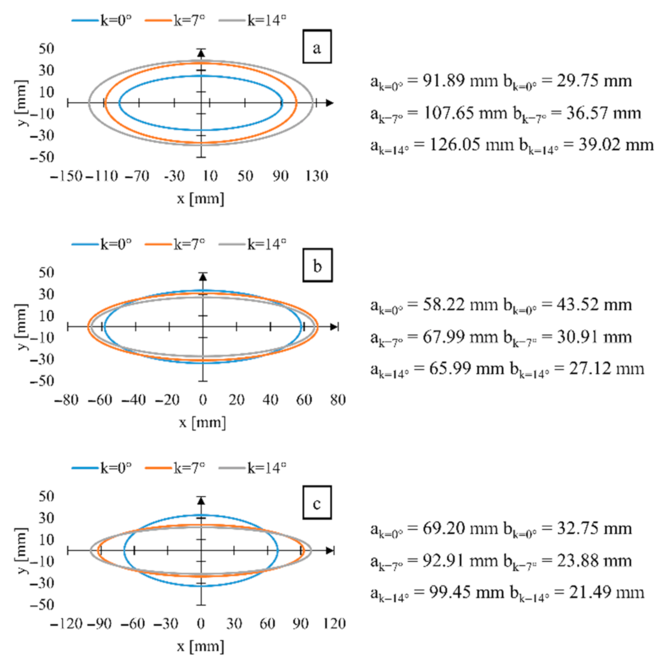
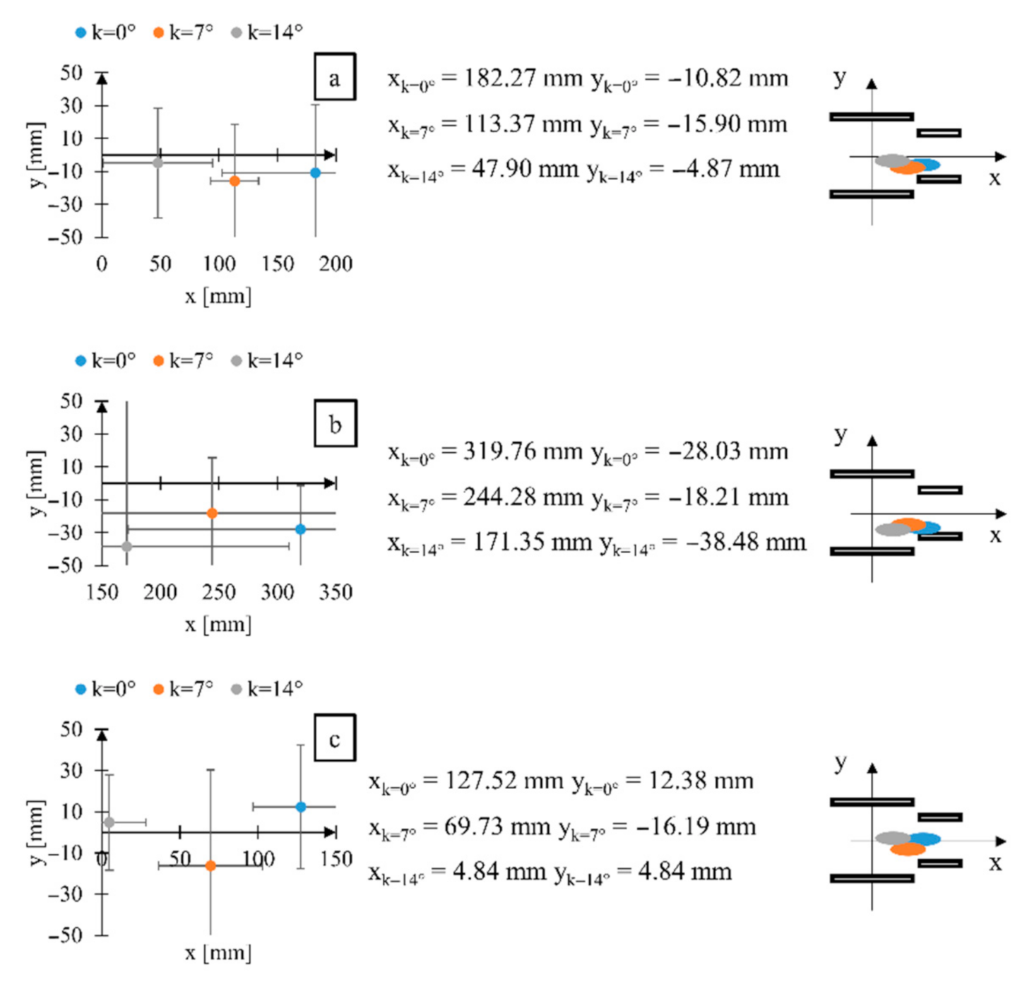
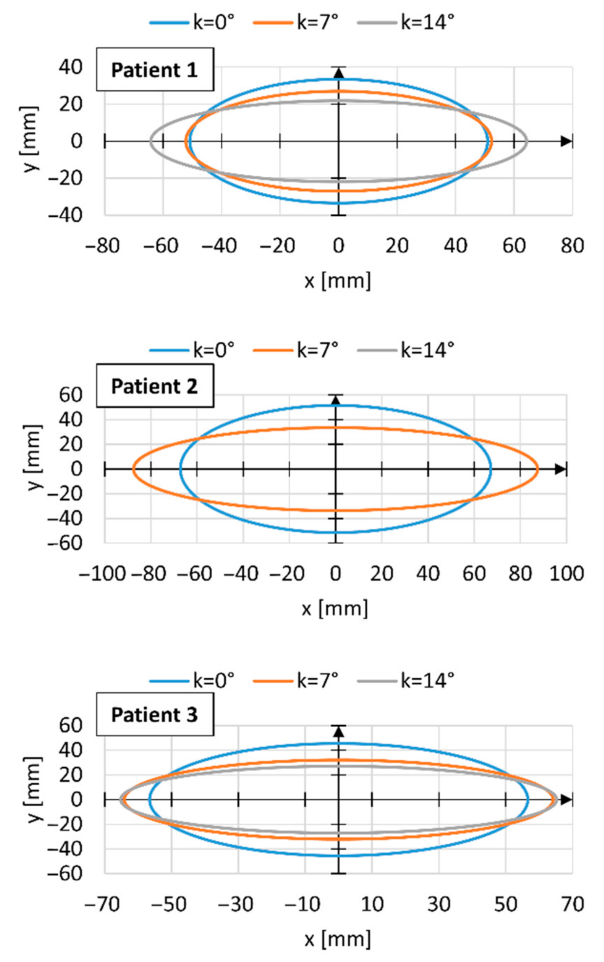
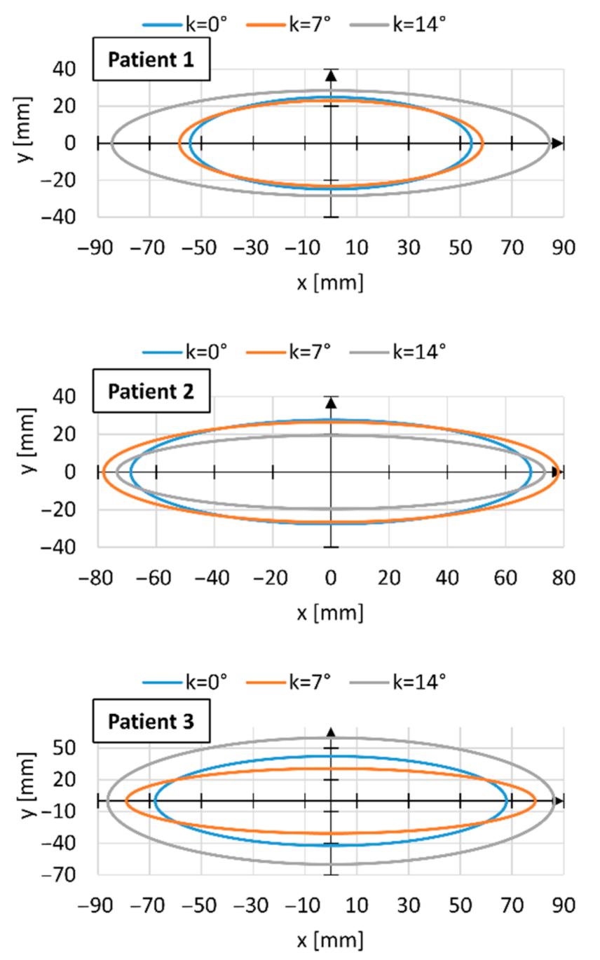
| a | (mm) | 91.89 | 107.65 | 126.05 | 108.53 | 17.08 |
| b | (mm) | 29.75 | 36.57 | 39.02 | 35.11 | 4.63 |
| α | (°) | −8.27 | −5.10 | −7.40 | −6.92 | 2.73 |
| x | (mm) | 182.27 | 113.37 | 47.90 | 114.51 | 67.19 |
| y | (mm) | −10.82 | −15.90 | −4.87 | −10.53 | 8.05 |
| k = 0° | k = 7° | k = 14° | M | Δ | ||
|---|---|---|---|---|---|---|
| a | (mm) | 58.22 | 67.99 | 65.99 | 64.07 | 5.89 |
| b | (mm) | 43.52 | 30.91 | 27.12 | 33.85 | 8.20 |
| α | (°) | 1.99 | −2.22 | −1.45 | −0.56 | 2.49 |
| x | (mm) | 319.77 | 244.28 | 171.35 | 245.13 | 74.91 |
| y | (mm) | −28.03 | −18.21 | −38.48 | −28.24 | 15.04 |
| k = 0° | k = 7° | k = 14° | M | Δ | ||
|---|---|---|---|---|---|---|
| a | (mm) | 69.20 | 92.91 | 92.45 | 87.19 | 15.13 |
| b | (mm) | 32.75 | 23.88 | 21.49 | 26.04 | 5.63 |
| α | (°) | −9.24 | −3.48 | −0.91 | −4.55 | 4.17 |
| x | (mm) | 127.52 | 69.73 | 4.84 | 67.36 | 61.34 |
| y | (mm) | 12.38 | −16.19 | 4.84 | 0.34 | 24.80 |
Publisher’s Note: MDPI stays neutral with regard to jurisdictional claims in published maps and institutional affiliations. |
© 2021 by the authors. Licensee MDPI, Basel, Switzerland. This article is an open access article distributed under the terms and conditions of the Creative Commons Attribution (CC BY) license (http://creativecommons.org/licenses/by/4.0/).
Share and Cite
Wieczorek, B.; Kukla, M.; Warguła, Ł. The Symmetric Nature of the Position Distribution of the Human Body Center of Gravity during Propelling Manual Wheelchairs with Innovative Propulsion Systems. Symmetry 2021, 13, 154. https://0-doi-org.brum.beds.ac.uk/10.3390/sym13010154
Wieczorek B, Kukla M, Warguła Ł. The Symmetric Nature of the Position Distribution of the Human Body Center of Gravity during Propelling Manual Wheelchairs with Innovative Propulsion Systems. Symmetry. 2021; 13(1):154. https://0-doi-org.brum.beds.ac.uk/10.3390/sym13010154
Chicago/Turabian StyleWieczorek, Bartosz, Mateusz Kukla, and Łukasz Warguła. 2021. "The Symmetric Nature of the Position Distribution of the Human Body Center of Gravity during Propelling Manual Wheelchairs with Innovative Propulsion Systems" Symmetry 13, no. 1: 154. https://0-doi-org.brum.beds.ac.uk/10.3390/sym13010154