Article

Three-Dimensional Investigation of Hydraulic Properties of Vertical Drop in the Presence of Step and Grid Dissipators

1
Department of Civil Engineering, Faculty of Engineering, University of Maragheh, Maragheh 8311155181, Iran
2
Department of Civil Engineering, Faculty of Engineering, University of Zanjan, Zanjan 537138791, Iran
3
CERIS, Instituto Superior Técnico, Universidade de Lisboa, 1049-001 Lisbon, Portugal
4
School of Engineering, University of St. Thomas, St. Paul, MN 55105, USA
*
Author to whom correspondence should be addressed.
Submission received: 28 April 2021 / Revised: 13 May 2021 / Accepted: 14 May 2021 / Published: 18 May 2021
(This article belongs to the Special Issue Turbulence and Multiphase Flows and Symmetry)

Abstract

:
In irrigation and drainage channels, vertical drops are generally used to transfer water from a higher elevation to a lower level. Downstream of these structures, measures are taken to prevent the destruction of the channel bed by the flow and reduce its destructive kinetic energy. In this study, the effect of use steps and grid dissipators on hydraulic characteristics regarding flow pattern, relative downstream depth, relative pool depth, and energy dissipation of a vertical drop was investigated by numerical simulation following the symmetry law. Two relative step heights and two grid dissipator cell sizes were used. The hydraulic model describes fully coupled three-dimensional flow with axial symmetry. For the simulation, critical depths ranging from 0.24 to 0.5 were considered. Values of low relative depth obtained from the numerical results are in satisfactory agreement with the laboratory data. The simultaneous use of step and grid dissipators increases the relative energy dissipation compared to a simple vertical drop and a vertical drop equipped with steps. By using the grid dissipators and the steps downstream of the vertical drop, the relative pool depth increases. Changing the pore size of the grid dissipators does not affect the relative depth of the pool. The simultaneous use of steps and grid dissipators reduces the downstream Froude number of the vertical drop from 3.83–5.20 to 1.46–2.00.

1. Introduction

Sometimes, during the construction of water supply systems, the natural slope of the ground is steeper than the slope required for the design. In such a situation, a drop is usually used to transfer water from a high level to a lower level and thus cause energy loss due to the increase of flow depth and decreasing the flow velocity. In addition to slope control, the drop structure also reduces the earthworks volume. One of the most critical issues to address downstream of a hydraulic structure is the flow’s kinetic energy [1]. The control structures must dissipate kinetic energy. Turbulence and water–air mixing are effective ways to increase energy dissipation. The use of grid structures and steps downstream of the vertical drop is a newer technique for energy dissipation. Grid dissipators are located in the path of a supercritical flow; they deposit the flow onto the downstream steps. By this process, they dissipate the destructive flows [2,3].
This study aims to investigate the effect of the simultaneous use of grid dissipators and steps downstream. Prior research, such as Esen, et al. [4], Rajaratnam and Chamani [5], Kabiri-Samani et al. [6], and Sharif and Kabiri-Samani [7] have studied the behavior of vertical drops and their influence on energy dissipation, bottom depth, and other performance metrics. Moore [8] was among pioneers who experimentally examined the velocity downstream of the vertical drop. The results showed that energy dissipation from these structures is a function of the relative critical depth. The main reason for energy dissipation is the impact of the vertical jets onto the bottom of the channel. Rajaratnam and Chamani [5] provided relationships for estimating pool depth and relative energy dissipation. It was inferred from the results that the return flow governs the depth of the pool to the drop wall (i.e., recirculating flow). Also, the free surface is approximated as a flat and rigid slip wall, and symmetry boundary conditions are applied for the resolved flow variables [9].
Esen et al. [4] used steps to reduce the destructive kinetic energy of the flow downstream of drops. By adding steps at different heights, the researchers showed that steps increase energy dissipation compared to a simple vertical drop. Kabiri-Samani et al. [6] investigated the behavior of vertical drops equipped with grid and groove dissipators; they showed that these dissipators increase energy dissipation. Sharif and Kabiri-Samani [7] investigated the effect of shallow depth on the behavior of a vertical drop equipped with grid dissipators. The results showed that increasing the downstream relative depth reduces water and bubble interference and increases the relative pool depth.
Daneshfaraz et al. [10] numerically investigated the effect of lattice plates and blocks on the energy dissipation of flow. From the results, it can be obtained that the use of screens and blocks increases energy dissipation. Daneshfaraz et al. [11] investigated the effect of double screens on vertical drops. The results showed that with increasing relative critical depth, the downstream relative depth and the relative residual energy also increase. Daneshfaraz et al. [1] also performed a laboratory study of energy dissipation on a drop equipped with screens. The results indicate that screens increase energy dissipation compared to a simple vertical drop. Daneshfaraz et al. [12] conducted an experimental study on the effect of horizontal screens diameter on hydraulic parameters of vertical drop. The results can be obtained that increasing the diameter of the screens does not affect the amount of energy dissipation. Daneshfaraz et al. [13] investigated the performance of the support vector machine on the prediction of hydraulic parameters of a vertical drop equipped with a horizontal screen with different diameters, which showed the excellent performance of SVM in predicting these parameters.
Previous research on slopes and the need to use this type of structure in irrigation and drainage channels show that one of the disadvantages that this structure exhibits (converting a steep slope into a more moderate design slope) lead to an increase in downstream kinetic energy, which is why little research has been done on these types of drops, including vertical and stepped drops. Falling flow through the pores of the grid dissipator increases air interference and increases the depth of flow. Simultaneous use of steps downstream of the vertical drop and grid dissipators increases the depth of the pool and the downstream depth of the stream and increases energy dissipation. On the other hand, the simultaneous use of steps and grid dissipators has not been studied numerically. Hence, the present study aims to comprehensively investigate the effect of steps and grid dissipators on the performance of a vertical drop in the plane of symmetry principle.

2. Materials and Methods

2.1. Turbulence Model

FLOW 3D is a software that is used for solving computational fluid dynamics (CFD) problems. The flow equations in this software are the Navier–Stokes’s equations and mass conservation [14]. This software solves Navier–Stokes’ equations discretized on finite volumes that subdivide the solution domain. The general forms of continuity and momentum are presented in Equations (1) and (2), respectively [15].
U i x j = 0
δ U i δ t i + ρ U i U i x i P x i + x i ( μ U i x j ρ u j u i ) + ρ g i u i
Here, Ui and u i are the mean and fluctuating velocities in the direction xi, where xi = (x, y, z), Ui = (U, V, W) and u i = (u’, v’, w’). The symbols ρ, μ, P and gi are specific gravity, dynamic viscosity, pressure, and gravitational acceleration. The instantaneous velocity is obtained by superposing the time-averaged and instantaneous fluctuating velocity ui = Ui + u i in all three directions. In the software, turbulence can be simulated using the following turbulence models:
  • Large Vortex Simulation Model (LES),
  • Model of two equations (k-ɛ),
  • Model of Re-Normalized Group (RNG),
  • Prandtl mixing length.
In the present study, the Re-Normalized Group (RNG) turbulence model was selected. The reason for using this turbulence model is its ability to simulate a flow with a large computational mesh, good performance in simulating flow separation, superior results with sudden strain and curvature, as well as success in previous numerical studies [16,17,18,19,20]. The RNG (k-ɛ) model is a two-equations model that is expressed as [21,22]:
δ U i δ t i + ρ U i U i x i P x i + x i ( μ U i x j ρ u j u i ) + ρ g i u i
t ( ρ ε ) + ( ρ ε u i ) x i = x j ( α s μ e f f k x j ) + C 1 s ε k ( G k + G 3 s G b ) + C 2 s ρ ε 2 k R ε + S ε
In these equations, k is the turbulent kinetic energy; ɛ is the turbulence dissipation rate; Gk is the production of turbulent kinetic energy due to velocity gradient; Gb is turbulent kinetic energy production from buoyancy, and YM is turbulence dilation oscillation distribution [15,23,24]. In the above equations, αk = αs = 1.39, C1s= 1.42 and C2s = 1.6 are model constants. The terms Sk and Sε are source terms for k and ɛ, respectively. The turbulent viscosity is added to the molecular viscosity to obtain μeff effective viscosity. The volume of fluid (VOF) method consists of three main components: fluid ratio function, VOF transport equation solution, and boundary conditions at the free surface. The VOF transport equation is expressed by Abbasi, et al. [25]:
F t + 1 V F ( F A x u ) x + ( F A y v ) y + ( F A z w ) z = 0

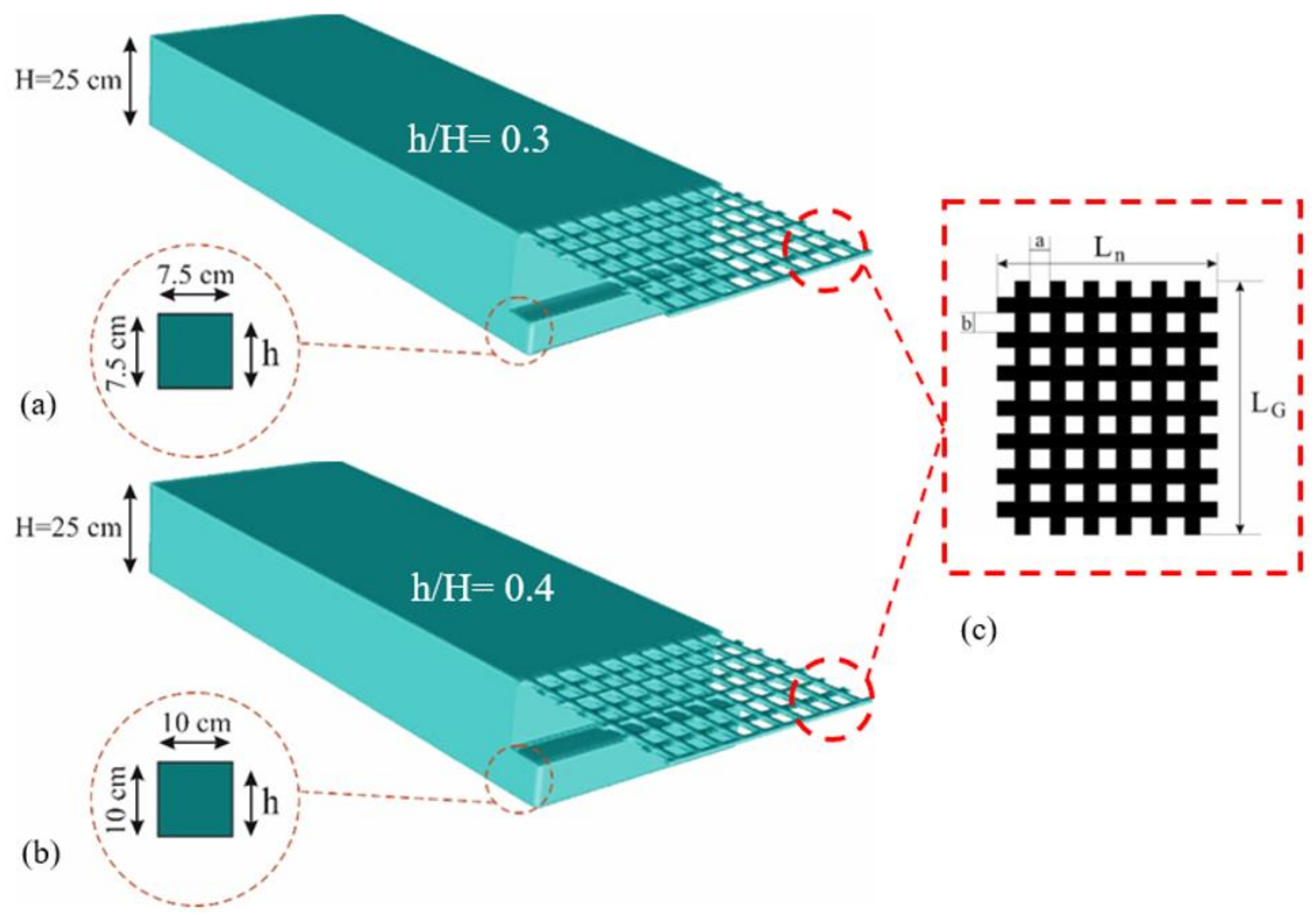
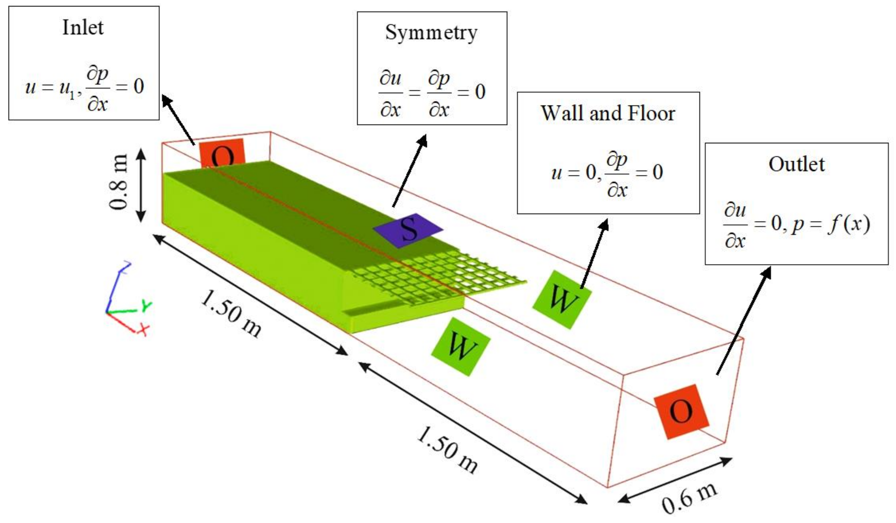
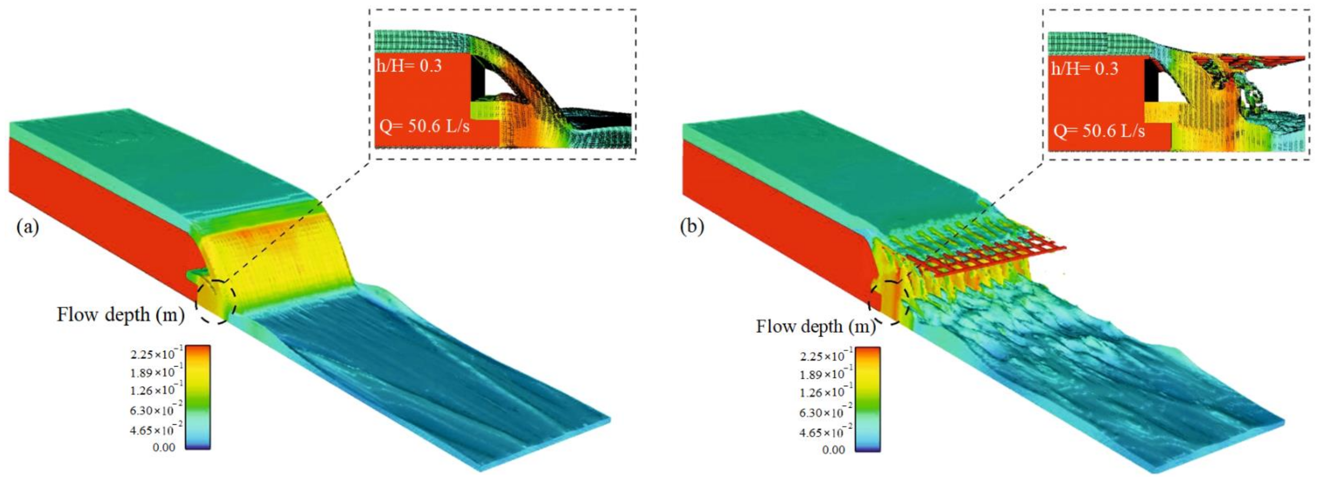
2.2. Simulation Specification and Solution Field Network

Two steps with heights of 7.5 and 10 cm and two grid dissipators with cell sizes 6 × 6 and 4 × 4 cm were employed to investigate the simultaneous effect of steps and grid dissipators. The grids have porosities of 56% and 44%, respectively (Table 1).
The height of the drop structure is 25 cm, and a total of 82 simulations were completed. For validation, the numerical model results were compared with the laboratory data of Esen et al. [4]. Those researchers used a laboratory flume with a width of 0.6 m, a height of 0.78 m and a length of 20 m, three drop heights, and seven different step heights. The height of their drop was 25 cm, and the heights of their steps were 7.5 and 10 cm. For validation, the relative downstream depth corresponding to a drop height of 25 cm and a step height of 7.5 cm was used. Figure 1 shows a three-dimensional view of a vertical drop with steps and grid dissipators. In Figure 1, Ln and LG are the grid dissipator length and width, respectively. The amount of Ln is equal to the width of the channel, where the LG is equal to 40 cm, for which the amount of grid length has been used from the Kabiri-Samani et al. [6] study.
The boundary conditions used in the present study are as follows:
(i)
inlet boundary = volume flow rate (VFR),
(ii)
outlet boundary = outflow,
(iii)
the bottom and side, boundary = Wall, v: the top boundary = symmetry.
After applying the boundary conditions, the time required for the flow stability time was 35 s which is the steady-state in all models in the 20th second. The time step was 0.01 s. Table 2 shows the range of operating parameters, and Figure 2 shows the geometric characteristics of the vertical slope with boundary conditions in the presence of a step and a grid dissipator. It should be noted that the type of mesh used in this study is a cartesian.

2.3. Dimensional Analysis

Relevant parameters are annotated in Figure 3. A functional relationship between the various parameters is provided mathematically in Equation (6), where f1 is an undefined functional relationship.
f 1 ( Q , ρ , μ , g , y u , y d , y b , H , h , B , a , b , y p , y c , ε , E u , E d ) = 0
In Equation (6), Q is the discharge [L3T−1], ρ is density [ML−3], μ is the kinematic viscosity [ML−1T−1], g is the gravitational acceleration [LT−2], yu is the upstream depth [L], yd is the downstream depth [L], yb represents the edge of the drop depth [L], H is the drop height [L], h is the step height [L], B refers to the channel width [L], a and b are the length and width. The grid dissipators are also annotated [L], Eu is the upstream specific energy [L], Ed is the downstream specific energy [L], yp refers to the pool depth [L], yc to the critical depth [L] and ɛ is the grid dissipator porosity [-]. Using the Pi–Buckingham method and considering the parameters ρ, g, and yu as iterative parameters, dimensional analysis can be performed. Relative energy dissipation and downstream relative depth are extracted as dimensionless parameters according to Equation (7):
f 2 ( F r u , Re u , y d y u , y b y u , H y u , h y u , B y u , a y u , b y u , y p y u , y c r y u , E u y u , E d y u , ε ) = 0
By simplifying and dividing dimensionless parameters, Equation (8) is obtained as follows:
y d H , Δ E E u , y p H = f 3 ( F r u , Re u , y b H , h H , B H , a b , y c r H , ε )
Given that the flow is turbulent and the Reynolds number is 160,000–399,000, the viscous effects are ignored. Additionally, the parameters a/b, B/H, and yb/H were removed because of their lack of influence on the results. The Fru parameter, which indicates the upstream Froude number, is subcritical in all models, and it was also eliminated [8] so that:
Δ E E u , y d H , y p H = f 5 ( h H , y c r H , ε )

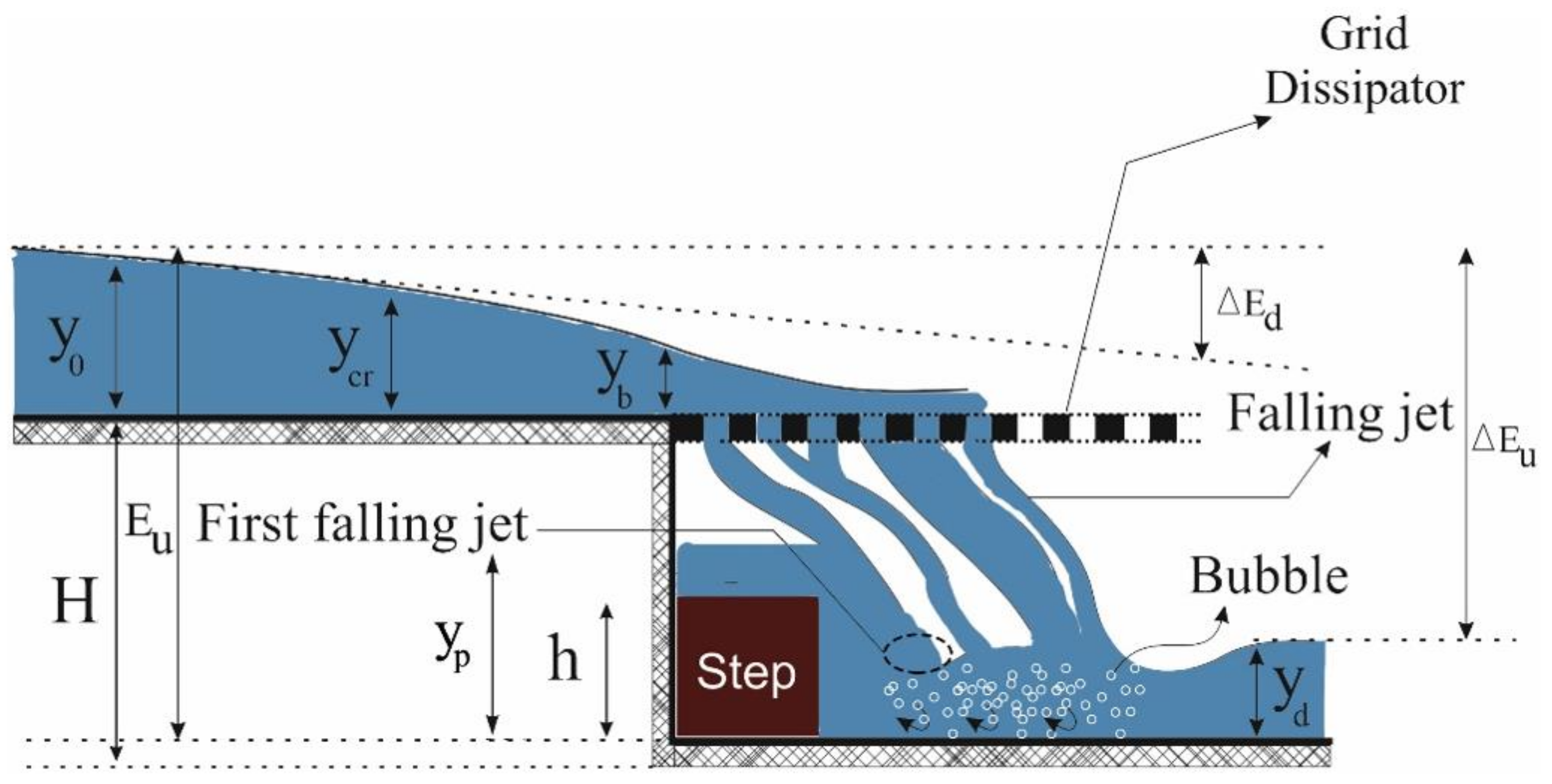
2.4. Classical Hydraulic Equations and Evaluation Criteria
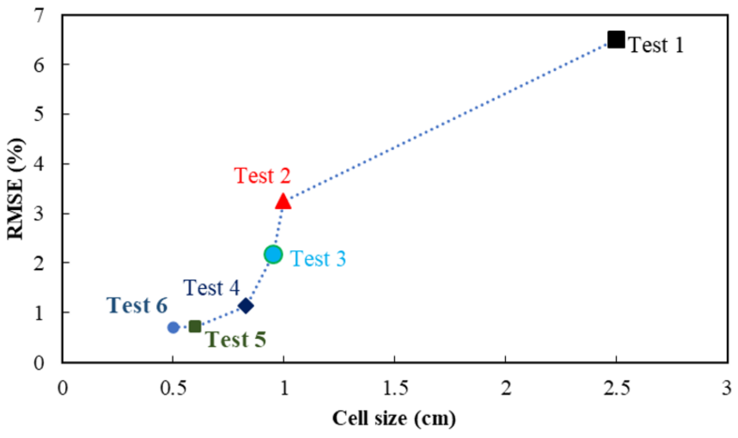
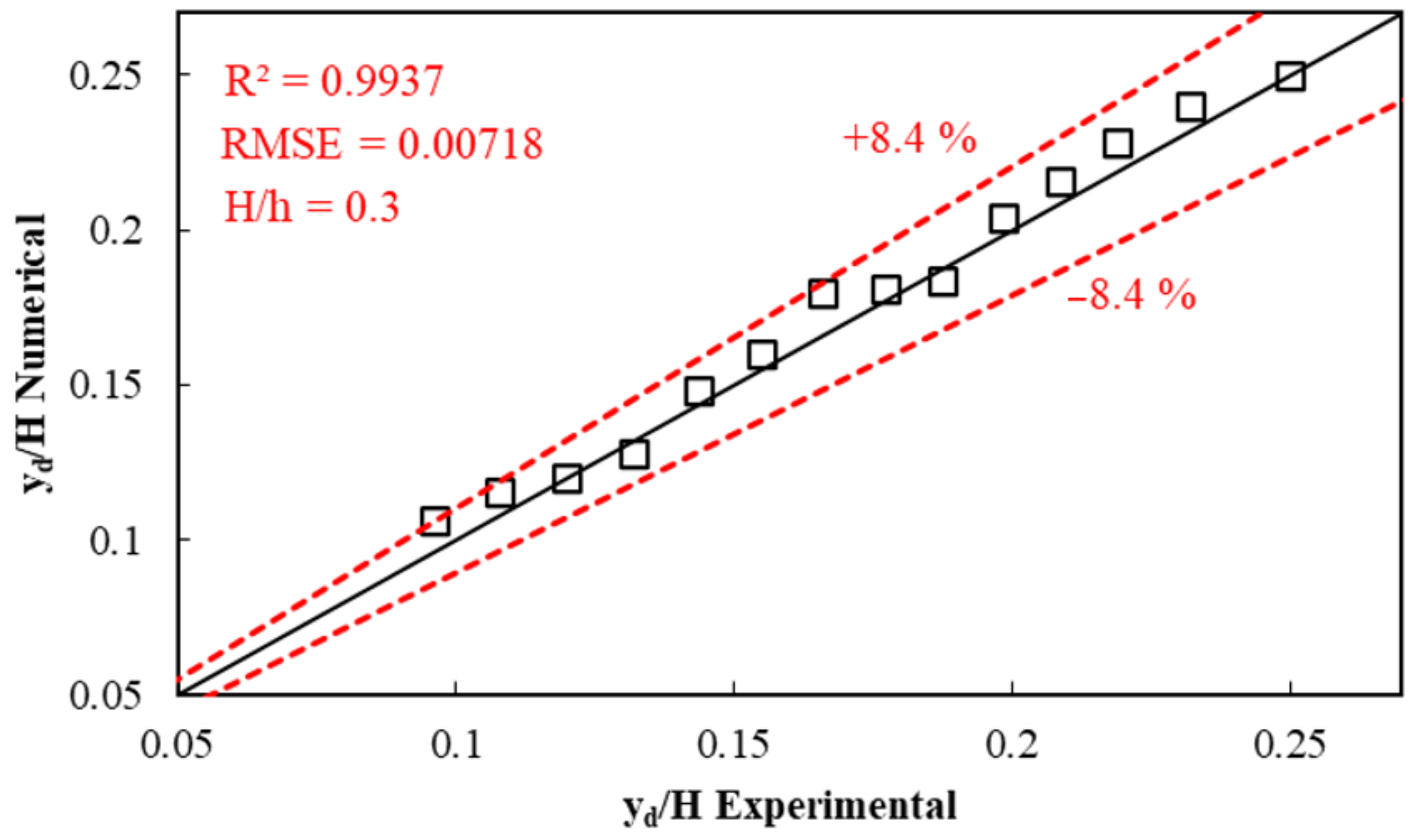
One parameter to be studied is the relative energy dissipation of the flow. The specific energy upstream and downstream of the drop are calculated from Equations (10) and (11), respectively. Additionally, R2 and RMSE were used to evaluate the agreement between the calculations and the measurements. RMSE refers to the root mean square errors, R2 is the coefficient of determination, and n is the total number of data points. The metrics above were computed using Equations (12) and (13), respectively. It should be noted that the optimal answer is one in which the RMSE and R2 parameters tend to zero and one, respectively.
E u = H + 1.50 y c
E d = y d + q 2 2 g y d 2
R M S E = i = 1 n y d H E x p y d H N u m 2 n
R 2 = i = 1 n y d H E x p y d H E x p ¯ × y d H N u m y d H N u m ¯ 2 i = 1 n y d H E x p y d H E x p ¯ 2 × i = 1 n y d H N u m y d H N u m ¯ 2

2.5. Validation

A mesh independence study was performed with increasing computational elements until the results were no longer materially dependent on the element sizes. Table 3 summarizes the mesh-independence results, and Figure 4 indicates the RMSE values for various meshes.
The mesh with 3,350,000 elements resulted in a root mean square error and a coefficient of determination of 0.781% and 0.993, respectively. This mesh was selected for performing further calculations. Figure 5 was prepared to relate the relative experimental and predicted depths downstream of the vertical drop. It is seen that the two results agree to within ±8.4%. Test 6 also has very good results, but because the number of evaluation parameters RMSE and R2 are very close to the values of test 5, to reduce the number of meshes, test specification 5 was used to continue the simulation.

3. Results and Discussion

3.1. Water Surface Profile

Flow profiles along the route reflect the water depth. It is usually possible to design canal walls based on flow profiles [10]. At the same time, the velocity profiles on the plane of symmetry downstream of the vertical drop may be analyzed together where a significant thickness of the fluid covers the structure [26]. Thus, measurements were carried out in the vertical plane of symmetry, downstream of the vertical. The flow surface profile over a vertical drop with a continuous step with relative height 0.4 and relative critical depth 0.24 is shown in Figure 6a.
Additionally, shown is a flow profile over a vertical drop equipped with steps with a relative height of 0.3. There are also grid dissipators with cell sizes of 4 × 4 cm, as shown in Figure 6b. According to Figure 6a,b, it can be inferred that after the fluid flows past the vertical drop, some of the flow passes through the grid dissipator pores and subsequently falls downstream as a jet. Some of the discharge returns upstream to the vertical drop wall, causing turbulence behind the jet. Some of the flow impacts the steps installed at the bottom of the drop. It was proposed that this phenomenon is due to the influence of the recirculation vortex, which entrained the inner portions of the vortex and drew the flow pattern towards the axis of symmetry [26,27,28].

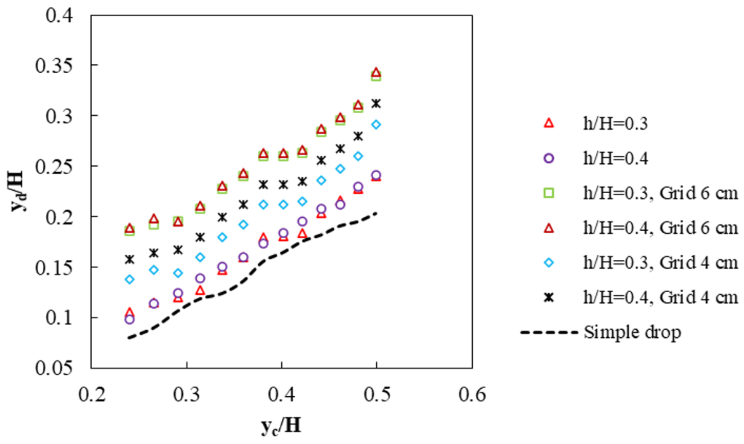
3.2. Relative Downstream Depth

Based on the dimensional analysis, the values of the relative downstream depth are plotted versus the relative critical depths in Figure 7.
It is observed that with increasing relative critical depth, the downstream relative depth values increase in all scenarios. According to Figure 7, it is clear that for step heights, the value of the downstream relative depth increases with the use of grid dissipators. The jet flow downstream of the vertical drop passes through the pores in the grid dissipator. This process increases the water and air interference and increases oxygen in the water. This mixing also increases the downstream depth.
On the other hand, some of the flow reverses direction and travels upstream toward the vertical drop wall. The reversed flow increases turbulence behind the jet—a portion of the flow impacts the steps installed at the bottom of the drop. The presence of steps and the increase of the relative height (caused by the grid dissipators) causes a 32% increase in relative downstream depth for two relative heights of 0.3 and 0.4. Simultaneous use of steps and a grid reduces the Froude number of the vertical drop. Reduction of the Froude number is a significant quantity that provides insight into the stilling basins’ economic design. The range of Froude numbers for the present study is presented in Table 4.

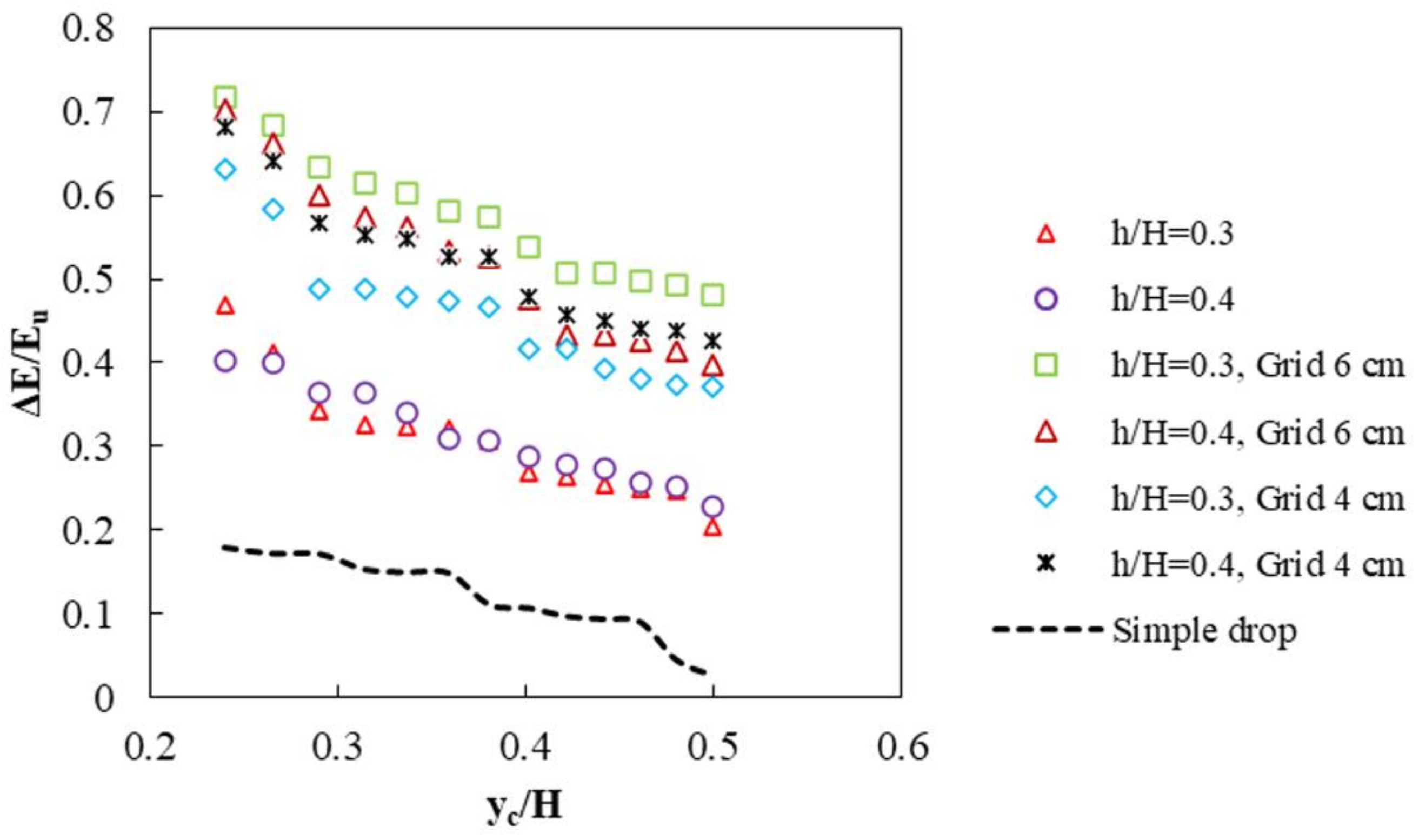
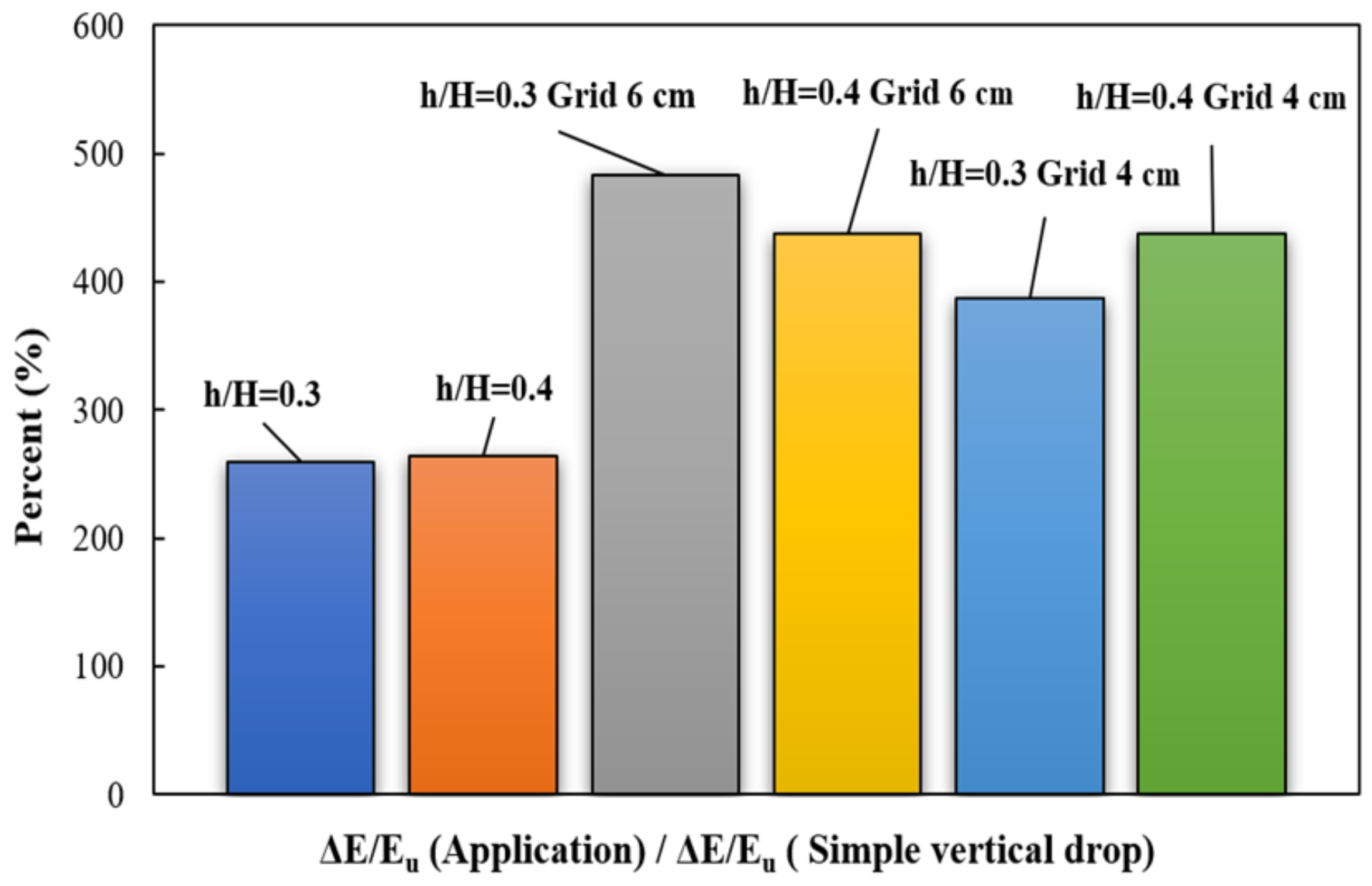
3.3. Relative Energy Dissipation

Relative energy dissipation values for flow over a simple vertical drop, a vertical drop equipped with steps, and a vertical drop equipped with steps and grid dissipators are indicated in Figure 8.
The data was extracted for two relative step heights and two grid-cell sizes. It is observed that for all models of a simple vertical drop, with increasing relative critical depth, the relative energy dissipation decreases. The minimum energy dissipation values occur with a simple vertical drop. In contrast, a maximum energy dissipation corresponds to a drop equipped with a vertical grid dissipator and a step with a relative step height of 0.3 and a grid size of 6 cm. The minimum energy reduction was 259%, whereas the maximum reduction is 483% (compared to the simple vertical drop case). Results are shown in Figure 9, where the significant effect on energy dissipation is evident. After flow passes over the vertical drop with a step, a portion of the flow passes through the dissipator holes. Following the dropping jets, some of the fluid flows towards the drop wall.
The vertical drop results in enhanced turbulence behind the jet, and some of the flow passes onto the step installed at the bottom of the drop. The decrease of the relative energy dissipation for a vertical drop with a relative step height of 0.4 and dissipator cell size of 4 and 6 cm is almost the same; modifications to the grid cell size have minimal effect on the degree of energy dissipation.
Given that grid dissipators significantly increase energy dissipation, the use of these structures also has limitations, such as blocking the pores of these grids. Suppose debris accumulates over these pores over the years. In that case, these pores will be blocked and will act as a vertical drop, and as the flow falls through it, the downstream flow regime will become supercritical. To expand this issue, we can mention the use of grooved grids because in this case, there is no hole, and it will be grooved, and pore-clogging will not occur.

3.4. Relative Pool Depth
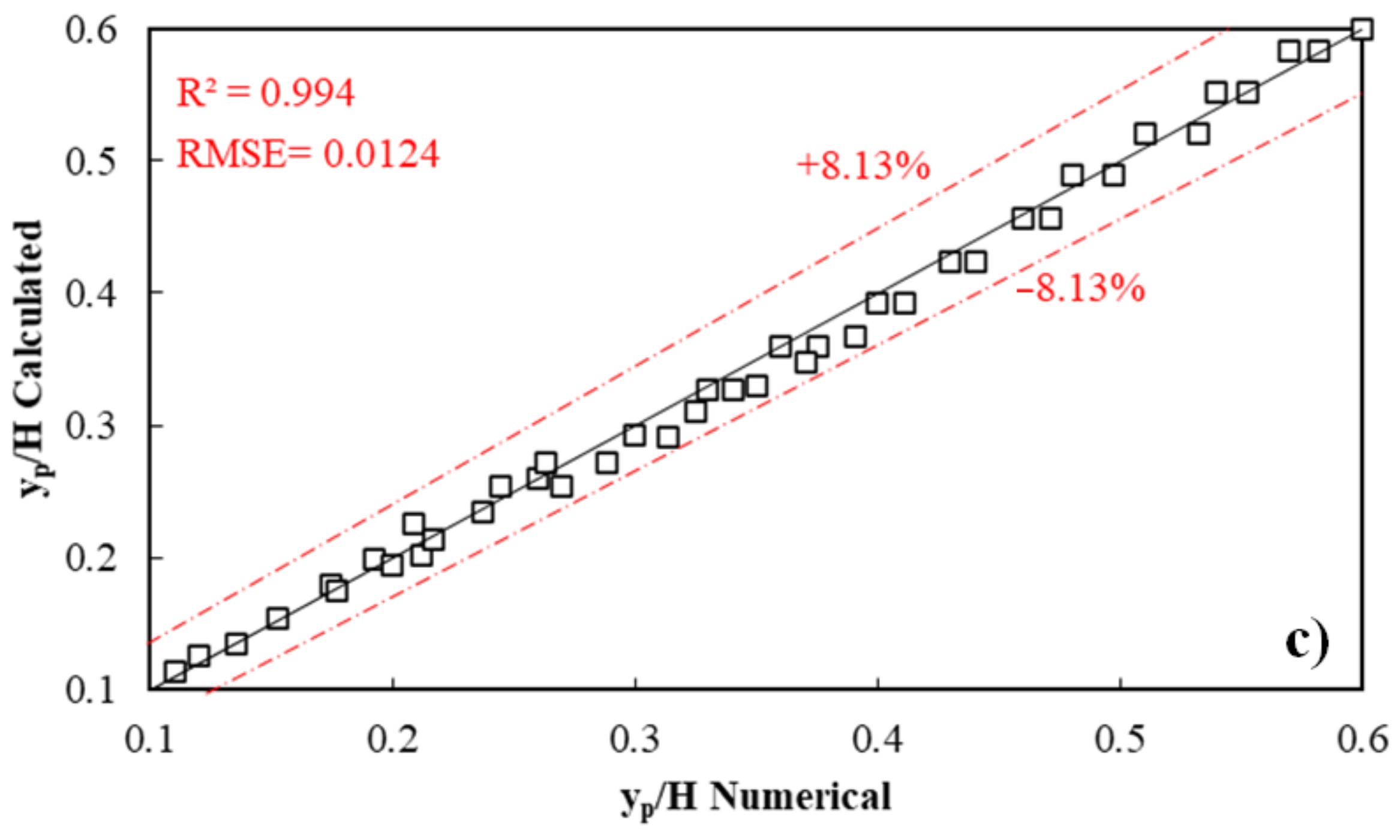
The relative pool depth values for the models studied in the present study versus the relative critical depth are shown in Figure 10. It is observed that in all models, increasing the relative critical depth increases the relative pool depth. The return flow discharge to the pool and the immersion created by the interference of the flow passing through the pores of the grid dissipators increases. This hydraulic phenomenon causes the relative critical depth and the relative pool depth as well. According to the figure, it can be seen that changing the size of the grid of grid dissipators does not affect the relative pool depth. However, compared to the model without grid dissipators, the relative pool depth in the vertical drop equipped with steps and dissipators has an increasing trend.

3.5. Equations

Equations were presented to investigate the effect of the input parameters and estimate the values of relative downstream depth and relative energy dissipation, and relative pool depth. These equations are used to estimate the energy dissipation and the relative downstream depth for a vertical drop structure equipped with a step. These equations were obtained by output data from Flow 3D software and then in Excel using the solver command. 30% of the data were selected for testing and 70% for training to develop the equations. Equations (14) and (15) are used to estimate the relative downstream depth and the relative energy dissipation; the values of its fixed parameters are shown in Table 5.
Δ E E u , y d H = a ( y c H ) b × c + d ( y c H ) e
y p H = a ( y c H ) b × ( h H ) c × ln ( ε )
After performing the predictive calculations, the values were compared with the results from the numerical simulation, as shown in Figure 11.
As can be deduced from the figure, for all cases, the relative downstream depth can be predicted with root mean square error and the coefficient of determination values of 0.023 and 0.980, respectively. The relative energy is predicted with root mean square error and coefficient of determination values equal to 0.0228 and 0.973. Similarly, the relative pool depth is predicted with root mean square error and coefficient of determination values equal to 0.0124 and 0.993, respectively. The predictions have maximum relative errors of ±5.8% and ±8.9%, and ±8.13%, respectively (as evident from the following images).

4. Conclusions

In the present study, the simultaneous use of a step downstream of a vertical drop and grid dissipators was studied using FLOW 3D software. The VOF method was used to simulate the free surface, and the RNG (k-ɛ) model was used to calculate turbulence. The relative downstream depth for the vertical drop equipped with a step obtained agrees very closely with measurements. Simultaneous use of a step and grid dissipators increases the relative downstream depth and increases relative energy dissipation. The relative energy dissipation decreases with increases to the relative critical depth. A vertical drop equipped with a step has less energy dissipation than a vertical drop equipped with a step and grid dissipator. Simultaneous use of steps with a height of 7.5 cm and a grid dissipator with a cell size of 6 cm increases the relative energy dissipation energy by more than 4.8 times compared to a simple vertical drop. The relative energy dissipation for the vertical drop with a relative step height of 0.4 and cell sizes of 4 and 6 cm grid are nearly identical. The use of steps and grid dissipators caused a 62% reduction in the Froude number compared to the simple vertical drop so that the range of Froude numbers has changed from a range of 3.83–5.20 to 1.46–2.00. Therefore, reducing the Froude number with grid dissipators can cause severe turbulence and enhanced air–water mixing.

Author Contributions

Conceptualization, R.D.; E.A.; A.G.; A.K. and J.A.; methodology, E.A., and A.G.; software, E.A., and A.G.; validation, E.A.; A.G. and A.K.; formal analysis, E.A.; A.G. and A.K.; investigation, R.D.; E.A.; A.G.; A.K. and J.A.; resources, E.A. and A.G.; data curation, E.A., and A.G.; writing—original draft preparation, R.D.; E.A.; A.G.; A.K. and J.A.; writing—review and editing, R.D.; E.A.; A.G.; A.K. and J.A.; visualization, E.A., and A.G.; supervision, R.D.; project administration, R.D, and A.G. All authors have read and agreed to the published version of the manuscript.

Funding

This research received no external funding.

Institutional Review Board Statement

Not applicable.

Informed Consent Statement

Not applicable.

Data Availability Statement

Data is contained within the article.

Conflicts of Interest

The authors declare no conflict of interest.

References

  1. Daneshfaraz, R.; Majedi Asl, M.; Bazyar, A.; Abraham, J.; Norouzi, R. The laboratory study of energy dissi-pation in inclined drops equipped with a screen. J. Appl. Water Eng. Res. 2020, 1–10. [Google Scholar] [CrossRef]
  2. Daneshfaraz, R.; Bagherzadeh, M.; Esmaeeli, R.; Norouzi, R.; Abraham, J. Study of the performance of support vector machine for predicting vertical drop hydraulic parameters in the presence of dual horizontal screens. Water Supply 2020, 21, 217–231. [Google Scholar] [CrossRef]
  3. Daneshfaraz, R.; Bagherzadeh, M.; Ghaderi, A.; Di Francesco, S.; Asl, M.M. Experimental investigation of gabion inclined drops as a sustainable solution for hydraulic energy loss. Ain Shams Eng. J. 2021. [Google Scholar] [CrossRef]
  4. Esen, I.I.; Alhumoud, J.M.; Hannan, K.A. Energy Loss at a Drop Structure with a Step at the Base. Water Int. 2004, 29, 523–529. [Google Scholar] [CrossRef]
  5. Rajaratnam, N.; Chamani, M.R. Energy loss at drops. J. Hydraul. Res. 1995, 33, 373–384. [Google Scholar] [CrossRef]
  6. Kabiri-Samani, A.; Bakhshian, E.; Chamani, M. Flow characteristics of grid drop-type dissipators. Flow Meas. Instrum. 2017, 54, 298–306. [Google Scholar] [CrossRef]
  7. Sharif, M.; Kabiri-Samani, A. Flow regimes at grid drop-type dissipators caused by changes in tail-water depth. J. Hydraul. Res. 2018, 56, 505–516. [Google Scholar] [CrossRef]
  8. Moore, W.L. Energy Loss at the Base of a Free Overfall. Trans. Am. Soc. Civ. Eng. 1943, 108, 1343–1360. [Google Scholar] [CrossRef]
  9. Paik, J.; Escauriaza, C.; Sotiropoulos, F. Coherent structure dynamics in turbulent flows past in-stream structures: Some insights gained via numerical simulation. J. Hydraul. Eng. 2010, 136, 981–993. [Google Scholar] [CrossRef]
  10. Daneshfaraz, R.; Sadeghfam, S.; Ghahramanzadeh, A. Three-dimensional numerical investigation of flow through screens as energy dissipators. Can. J. Civ. Eng. 2017, 44, 850–859. [Google Scholar] [CrossRef]
  11. Daneshfaraz, R.; Asl, M.M.; Razmi, S.; Norouzi, R.; Abraham, J. Experimental investigation of the effect of dual horizontal screens on the hydraulic performance of a vertical drop. Int. J. Environ. Sci. Technol. 2020, 17, 2927–2936. [Google Scholar] [CrossRef]
  12. Daneshfaraz, R.; Ghaderi, A.; Di Francesco, S.; Khajei, N. Experimental study of the effect of horizontal screen diameter on hydraulic parameters of vertical drop. Water Supply 2021. [Google Scholar] [CrossRef]
  13. Daneshfaraz, R.; Aminvash, E.; Ghaderi, A.; Abraham, J.; Bagherzadeh, M. SVM Performance for Predicting the Effect of Horizontal Screen Diameters on the Hydraulic Parameters of a Vertical Drop. Appl. Sci. 2021, 11, 4238. [Google Scholar] [CrossRef]
  14. Ghaderi, A.; Dasineh, M.; Aristodemo, F.; Aricò, C. Numerical Simulations of the Flow Field of a Submerged Hydraulic Jump over Triangular Macroroughnesses. Water 2021, 13, 674. [Google Scholar] [CrossRef]
  15. Ghaderi, A.; Abbasi, S.; Abraham, J.; Azamathulla, H.M. Efficiency of Trapezoidal Labyrinth Shaped stepped spillways. Flow Meas. Instrum. 2020, 72, 101711. [Google Scholar] [CrossRef]
  16. Akoz, M.S.; Soydan, N.G.; Simsek, O. Numerical validation of open channel flow over a curvilinear broad-crested weir. Prog. Comput. Fluid Dyn. Int. J. 2016, 16, 364. [Google Scholar] [CrossRef]
  17. Ghaderi, A.; Dasineh, M.; Aristodemo, F.; Ghahramanzadeh, A. Characteristics of free and submerged hydraulic jumps over different macroroughnesses. J. Hydroinformatics 2020, 22, 1554–1572. [Google Scholar] [CrossRef]
  18. Lai, Y.G.; Wu, K. A Three-Dimensional Flow and Sediment Transport Model for Free-Surface Open Channel Flows on Unstructured Flexible Meshes. Fluids 2019, 4, 18. [Google Scholar] [CrossRef] [Green Version]
  19. Ghaderi, A.; Abbasi, S. Experimental and Numerical Study of the Effects of Geometric Appendance Elements on Energy Dissipation over Stepped Spillway. Water 2021, 13, 957. [Google Scholar] [CrossRef]
  20. Daneshfaraz, R.; Aminvash, E.; Esmaeli, R.; Sadeghfam, S.; Abraham, J. Experimental and numerical investigation for energy dissipation of supercritical flow in sudden contractions. J. Groundw. Sci. Eng. 2020, 8, 396–406. [Google Scholar]
  21. Ghaderi, A.; Abbasi, S.; Di Francesco, S. Numerical Study on the Hydraulic Properties of Flow over Different Pooled Stepped Spillways. Water 2021, 13, 710. [Google Scholar] [CrossRef]
  22. Yakhot, V.; Orszag, S.A.; Thangam, S.; Gatski, T.B.; Speziale, C.G. Development of turbulence models for shear flows by a double expansion technique. Phys. Fluids A Fluid Dyn. 1992, 4, 1510–1520. [Google Scholar] [CrossRef] [Green Version]
  23. Daneshfaraz, R.; Ghaderi, A.; Akhtari, A.; Di Francesco, S. On the Effect of Block Roughness in Ogee Spill-ways with Flip Buckets. Fluids 2020, 5, 182. [Google Scholar] [CrossRef]
  24. Ghaderi, A.; Daneshfaraz, R.; Dasineh, M.; Di Francesco, S. Energy Dissipation and Hydraulics of Flow over Trapezoidal–Triangular Labyrinth Weirs. Water 2020, 12, 1992. [Google Scholar] [CrossRef]
  25. Abbasi, S.; Fatemi, S.; Ghaderi, A.; Di Francesco, S. The Effect of Geometric Parameters of the Antivortex on a Triangular Labyrinth Side Weir. Water 2020, 13, 14. [Google Scholar] [CrossRef]
  26. Shamloo, H.; Rajaratnam, N.; Katopodis, C. Hydraulics of simple habitat structures. J. Hydraul. Res. 2001, 39, 351–366. [Google Scholar] [CrossRef]
  27. Sousa, J.L.; Carter, B.J.; Ingraffea, A.R. Numerical simulation of 3D hydraulic fracture using Newtonian and power-law fluids. Int. J. Rock Mech. Min. Sci. Geomech. Abstr. 1993, 30, 1265–1271. [Google Scholar]
  28. Bradbrook, K.F.; Lane, S.N.; Richards, K.S. Numerical simulation of three-dimensional, time-averaged flow structure at river channel confluences. Water Resour. Res. 2000, 36, 2731–2746. [Google Scholar] [CrossRef] [Green Version]
Figure 1. 3D view of a vertical drop equipped with steps and grid structures: (a) h/H = 0.3, (b) h/H = 0.4, and (c) the grid structure.
Symmetry 13 00895 g001
Figure 2. The geometric profile, vertical drop, and boundary conditions.
Symmetry 13 00895 g002
Figure 3. Geometric and hydraulic parameters for a vertical drop equipped with step and grid structures.
Symmetry 13 00895 g003
Figure 4. Variation of the RMSE versus cell size.
Symmetry 13 00895 g004
Figure 5. Comparison of experimental and numerical values of the relative depth downstream of the vertical drop with a step of 7.5 cm.
Symmetry 13 00895 g005
Figure 6. Flow over a vertical drop with h/H = 0.3: (a) drop equipped with a step, (b) drop equipped with both a step and grid structures.
Symmetry 13 00895 g006
Figure 7. Relative downstream depth versus relative critical depth.
Symmetry 13 00895 g007
Figure 8. Relative energy dissipation versus relative critical depth.
Symmetry 13 00895 g008
Figure 9. Energy dissipation is presented as relative to a simple vertical drop case.
Symmetry 13 00895 g009
Figure 10. Relative pool depth versus relative critical depth.
Symmetry 13 00895 g010
Figure 11. Comparison of predictions and measured results: (a) relative downstream depth, (b) relative energy dissipation, (c) relative pool depth.
Symmetry 13 00895 g011aSymmetry 13 00895 g011b
Table 1. Description of the grid dissipator.
DissipatorN4 × 4N6 × 6
a (cm)46
b (cm)46
Ln (cm)6060
LG (cm)4040
a/b1.01.0
ɛ (%)4456
Table 2. Range of parameters.
h/HDissipator Size (cm)Variables
yd (cm)yc (cm)Q (Lit/s)FrdReu (×104)
Without step-2.00–6.006.00–12.5027.60–64.503.83–5.2016–39.9
0.3-2.60–6.002.90–3.85
0.42.45–6.002.90–3.83
0.36 × 64.65–7.001.46–2.00
0.44.73–8.601.43–2.00
0.34 × 43.45–7.302.20–2.90
0.43.95–7.801.87–2.36
Table 3. Meshing sensitivity analysis.
Test No.Turbulence ModelCell Size (cm)Total Number of CellsRMSE (%)R2
Test 1RNG (k-ɛ)2.546,0806.5040.74
Test 2RNG (k-ɛ)1.0720,0003.2510.776
Test 3RNG (k-ɛ)0.95836,1362.1860.802
Test 4RNG (k-ɛ)0.831,856,2001.1360.89
Test 5RNG (k-ɛ)0.603,350,0000.7180.993
Test 6RNG (k-ɛ)0.505,253,0000.7080.995
Table 4. Meshing sensitivity analysis.
h/HGrid Cell Size (mm)Froude Number (Downstream)
Without stepWithout dissipator3.83–2.50
0.3Without dissipator2.90–3.85
0.4Without dissipator2.90–3.83
0.360 × 601.46–2.00
0.41.43–2.00
0.340 × 402.20–2.90
0.41.87–2.36
Table 5. Values of constant parameters of Equations (14) and (15).
Dependent ParametersConstant ParametersCriteria Parameters
abcdeRMSER2
y d H 0.4565−0.28080.34871.26201.42090.02230.980
Δ E E u 0.32260.80630.61590.36691.39210.02280.973
y p H 5.3251.3701.796-0.01240.993
Publisher’s Note: MDPI stays neutral with regard to jurisdictional claims in published maps and institutional affiliations.

