Article

The Symmetry of the Muscle Tension Signal in the Upper Limbs When Propelling a Wheelchair and Innovative Control Systems for Propulsion System Gear Ratio or Propulsion Torque: A Pilot Study

by
Łukasz Warguła
1,* and
Agnieszka Marciniak
2
1
Institute of Machine Design, Faculty of Mechanical Engineering, Poznan University of Technology, Piotrowo 3, 60-965 Poznań, Poland
2
Faculty of Mechanical Engineering, Poznan University of Technology, Piotrowo 3, 60-965 Poznań, Poland
*
Author to whom correspondence should be addressed.
Submission received: 7 April 2022 / Revised: 4 May 2022 / Accepted: 12 May 2022 / Published: 14 May 2022
(This article belongs to the Special Issue Symmetry and Asymmetry in Sport Sciences)

Abstract

:
Innovative wheelchair designs require new means of controlling the drive units or the propulsion transmission systems. The article proposes a signal to control the gear ratio or the amount of additional propulsion torque coming from an electric motor. The innovative control signal in this application is the signal generated by the maximum voluntary contraction (MVC) of the muscles of the upper limbs, transformed by the central processing unit (CPU) into muscle activity (MA) when using a wheelchair. The paper includes research on eight muscles of the upper limbs that are active when propelling a wheelchair. Asymmetry in the value for MVC was found between the left and right limbs, while the belly of the long radial extensor muscle of the wrist was determined to be the muscle with the least asymmetry for the users under study. This pilot research demonstrates that the difference in mean MVCmax values between the left and the right limbs can range from 20% to 49%, depending on the muscle being tested. The finding that some muscle groups demonstrate less difference in MVC values suggests that it is possible to design systems for regulating the gear ratio or additional propelling force based on the MVC signal from the muscle of one limb, as described in the patent application from 2022, no. P.440187.

1. Introduction

A contemporary trend in the design of machines and devices is used to increase safety [1,2,3], reduce energy consumption [4,5,6], and automate the processes involved [7,8,9]. Wheelchairs and devices that support the movement of people with disabilities and infirmities are propelled either manually [10,11,12] or electrically [13,14]. The disadvantage of manually propelled wheelchairs is the limited propelling force that can be generated by the wheelchair users themselves [15,16]. The use of such devices may lead to a situation where a person using a wheelchair cannot reach their destination, for example, due to excessive fatigue, changing weather conditions (strong winds or slushy surfaces) [17,18,19] or changing the route and additional obstacles from the terrain (steep hills) [20,21]. These factors limit the independence [22] and psychological comfort [23] of people using wheelchairs. Research by Rousseau-Harrison et al. in 2009 [24] and Wong and Yap in 2019 [25] indicates that reducing wheelchair users’ discomfort is beneficial to society as a whole. Electric wheelchairs have made a significant contribution to alleviating the above-mentioned problems, but their long-term and exclusive use is detrimental to the health of their users. People who use only electric wheelchairs have health problems due to limited physical activity [26]. The most advantageous and innovative solutions for people with disabilities and infirmities are wheelchairs equipped with gears (for manual propulsion systems) and assistive technology systems (for electric–manual hybrid propulsion systems) [27,28,29]. Wheelchairs equipped with assistive technology can support the movement of wheelchair users by adding tractive torque of a specific value transferred by electric motors to the wheelchair’s drive wheels. The amount of this torque can be declared by the user [29] or set by control algorithms based on signals from additional sensors, for example, those which use gyroscopic systems to recognize slopes [29]. Signals of the bioelectric potential of muscles, for instance, from the muscles of the face [30] and neck [31], can be used to set the direction and speed of travel for a wheelchair. However, it is not used for controlling wheelchairs using assistive technology. In 2020, Callejas-Cuervo et al. conducted a review of control systems and electronic instrumentation applied to autonomy in wheelchair mobility, showing that classic controller control is the most popular [32]. On the other hand, control with the use of bioelectric potential of muscles signals is designed to control electric wheelchairs in terms of speed control [33,34] and steering the driving direction [35]. A similar range of control using signals bioelectric potential of muscles was demonstrated by Kaur in 2021 in his review analysis wheelchair control for dis-abled patients using an electromyogram (EMG)/electrooculogram (EEA)-based human–machine interface [36].Conventional mechanical gears used in wheelchairs require manual gear shifting, which is very often associated with a loss of propelling force whilst shifting. In addition, the user adjusts the type of transmission on their own, which may not always be beneficial over longer distances. Manually propelled wheelchairs achieve the greatest efficiency when the load on the muscles is equal and constant. Changes in the push frequency and force values of the wheels may contribute to greater muscle fatigue and shorter distance of travel [37]. Excessive load on the muscles, e.g., when climbing hills, also limits the comfort of riding [38]. In order to design manually powered wheelchairs that provide a level of comfort in movement similar to electric–manual hybrid wheelchairs equipped with assistive technology systems, efforts were made to develop a gear shifting system for the propulsion system based on electrical signals generated from the muscle tension of the upper limbs. Changes in the propelling force used to move the wheelchair can be recorded based on the electrical signals generated by muscle tension (the bioelectric potential of the muscles) of the upper limbs, which can be used to select the propulsion system gear ratio in a manually propelled wheelchair or the drive torque in an electric wheelchair using assistive technology.
The control system at the initial stage of the project is intended for people with motor disabilities caused by an accident, and the spinal cord injury is related to the lumbar (L1–L5) or sacral (S1–S5) section. Damage to this extent and the absence of genetic diseases mean that the mobility of the upper limbs is not affected. The developed solution at this stage of the research is intended for use by people with muscle atrophy, because the propelling abilities of the upper limbs of such people are different for the left and right limbs. The authors strive to develop a single-limb monitoring system that would ensure the optimal selection of parameters for the comfortable driving of the wheelchair with the use of both limbs.
The paper aims to carry out exploratory research in order to determine the group of muscles in the upper limbs and the value of their signals and to enable the development of a system that would change the gear ratio based on these signals. The assumption of the control system is to measure the muscle tension on one of the arms; therefore, the tests are also intended to determine the phenomena of symmetry and asymmetry while propelling a wheelchair.

2. Materials and Methods

The commonly used Vermeiren v300 manual wheelchair with nominal tire pressure on a hard surface was used in the tests.
Ten people who had no genetic diseases took part in the test, and their disability resulted from accidents in which they suffered spinal cord injuries. The examined persons suffered damage to the spine of the lumbar (L1–L5) or sacral (S1–S5) spine. The spine injury in this section does not affect the mobility of the upper limbs. The subjects of the study are characterized in Table 1. The examined persons suffered damage to the spine of the lumbar (L1–L5) or sacral (S1–S5) spine. The spine injury in this section does not affect the mobility of the upper limbs. The subjects of the study are characterized in Table 1.
The participants were familiarized with the test procedure and signed a form of voluntary consent. The research was evaluated positively by the Bioethical Commission at Karol Marcinkowski Medical University in Poznań, Poland (Resolution No. 1100/16 of 10 November 2016), under the guidance of Prof. MD P. Chęciński for the research team led by B. Wieczorek, Ph.D. The authors obtained the subject’s written consent to publish the research results with their participation. The data are presented in such a way as to ensure complete anonymity.
The measurement of muscle activity, which enabled the upper limb muscle activity to be estimated, was conducted with a Noraxon Mini DTS apparatus for surface electromyography, equipped with four measurement channels. The analysis and recording of the muscle activity signal were carried out in the software program Noraxon MR3. Eight muscles involved in propelling a wheelchair were subjected to exercise stress analysis: biceps (A), triceps (B), deltoid middle head (C), long wrist extensor (D), deltoid anterior head (E), deltoid posterior head (F), and trapezius and subcapsular (G). Before commencing the actual muscle activity measurement, each participant went through a standardization procedure consistent with the guidelines of EMG [39], the manufacturer of the apparatus. This was carried out in order to determine a reference value necessary for subsequent calculations. A set of five dedicated exercises was carried out to test the maximum contraction of any muscle, which was selected based on the previous studies [15]. The recorded data were normalized successively, taking the arithmetic mean of the amplitude of the highest signal segment with a constant duration of 1000 ms as the reference value. Round electrodes (20 mm in diameter) with a gel were used in the tests. They were placed in the central part of the belly of the muscle being tested. The measurements were carried out at a frequency of 1500 Hz. Standardization was performed a day before the test to allow muscle regeneration after exertion during the standardization procedure. After a one-day rest, the participant performed the measurement test. The resulting EMG signals were rectified and then smoothed using root mean square algorithms with a window width of 150 ms (signal MVC). Later, the maximum voluntary contraction (MVCmax) test was performed for normalization test. This post-processing method uses a reference value to normalize subsequent EMG data series (1). The output is displayed as a percentage of the MA value, which can be used to easily establish a common ground when comparing data between repetitions and subjects.
M A = M V C M V C m a x · 100 %
where:
  • M A 
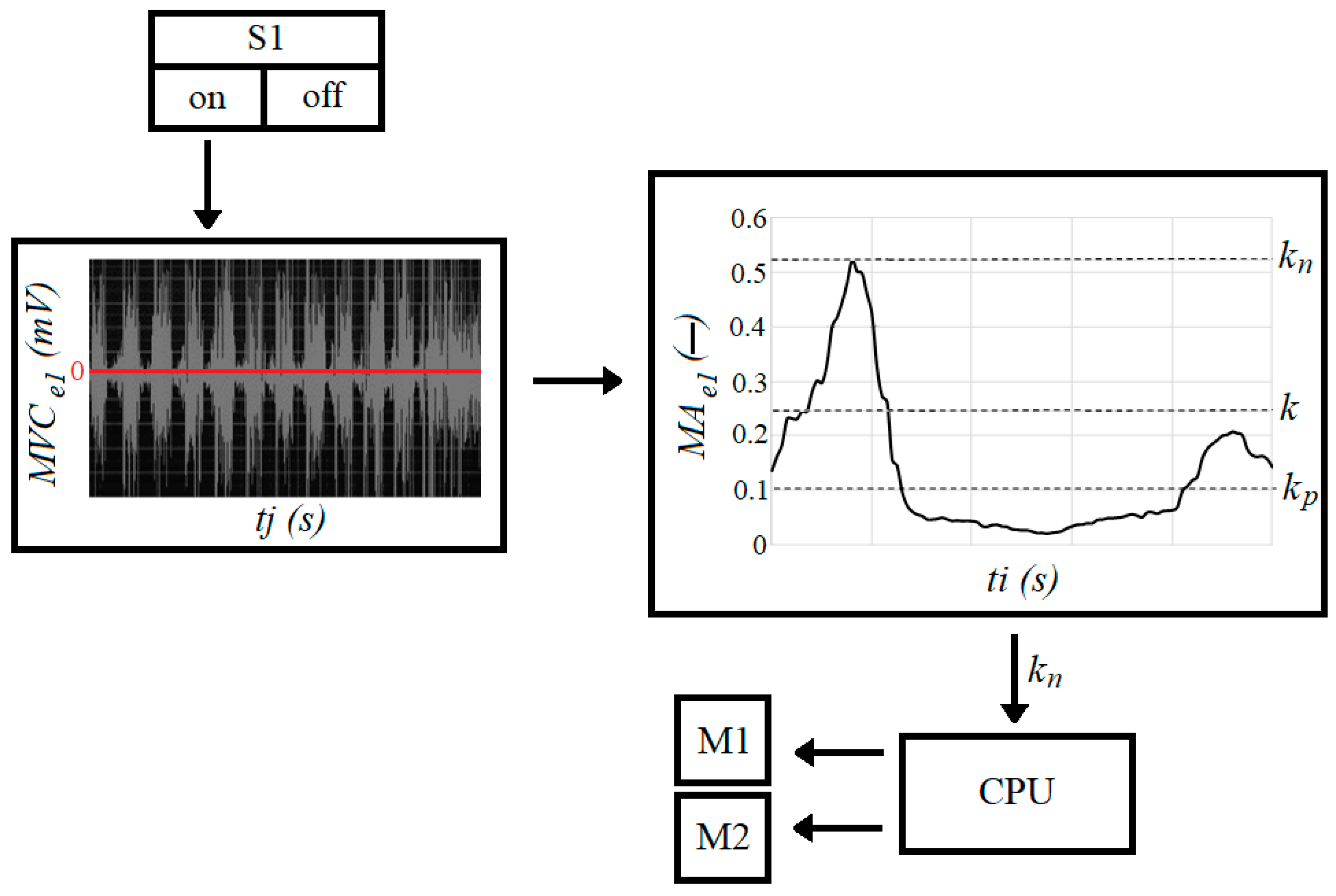
—muscle activity (expressed in %);
  • M V C 
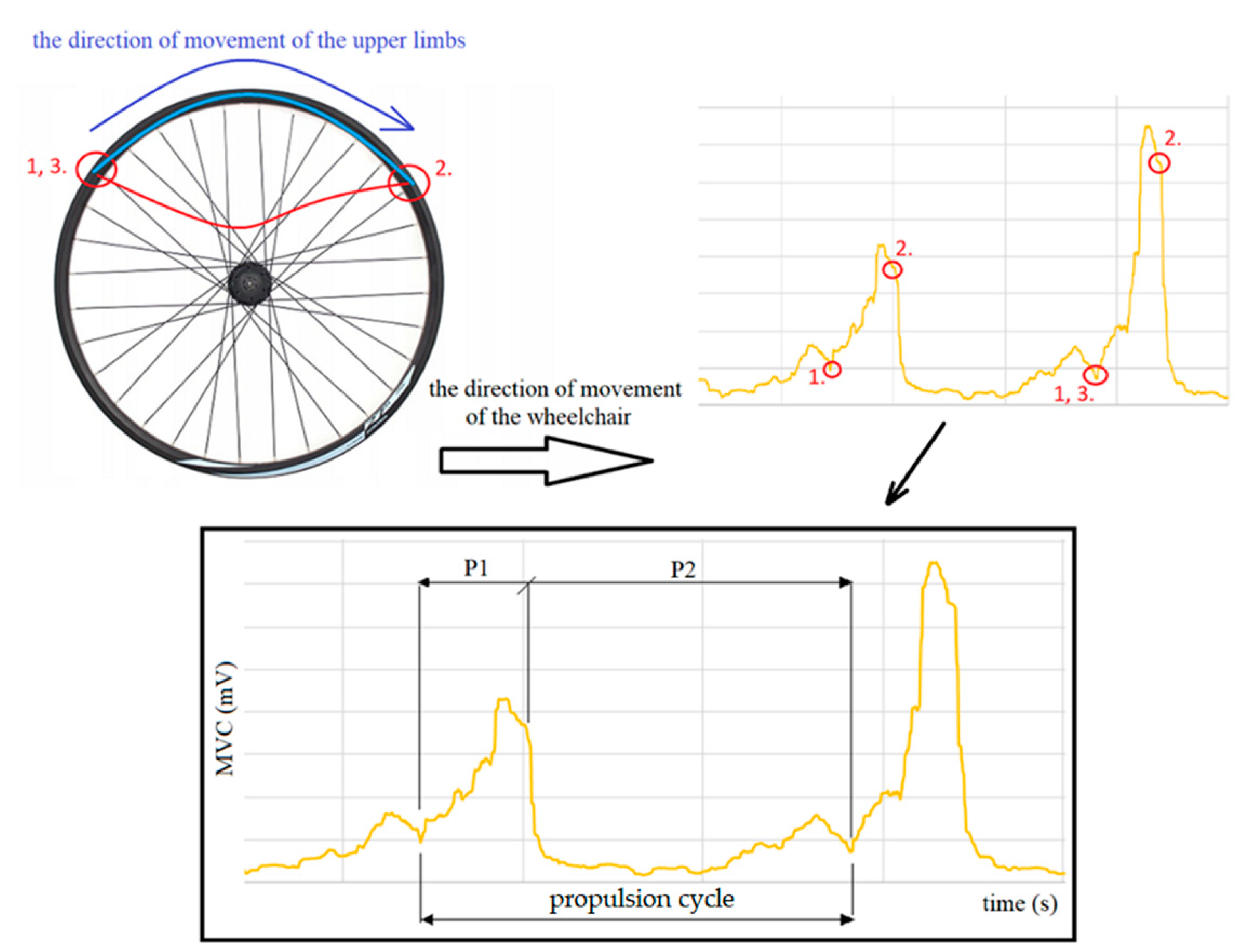
—maximum voluntary contraction during the propulsion phase (expressed in mV);
  • M V C m a x —maximum voluntary contraction during normalization test (expressed in mV).
In searching for muscle groups in the left and right upper limbs that would show a similar level of muscle activity, six measurement tests were carried out, during which the subject travelled on a wheelchair along a straight surface. They searched for the muscles with the lowest percentage of MVC difference between the right and left upper limbs.
Six complete driving cycles were identified for each patient. In each driving cycle, eight muscles were distinguished and muscle activity was identified. Based on the observation of the results, it was found that there is no normal distribution. On the basis of this observation, a statistical analysis was performed consisting in determining the confidence intervals for the mean calculated on the basis of the performed six repetitions. When determining the confidence intervals, the Student’s t-distribution and the 95% probability level (p = 0.05) were used

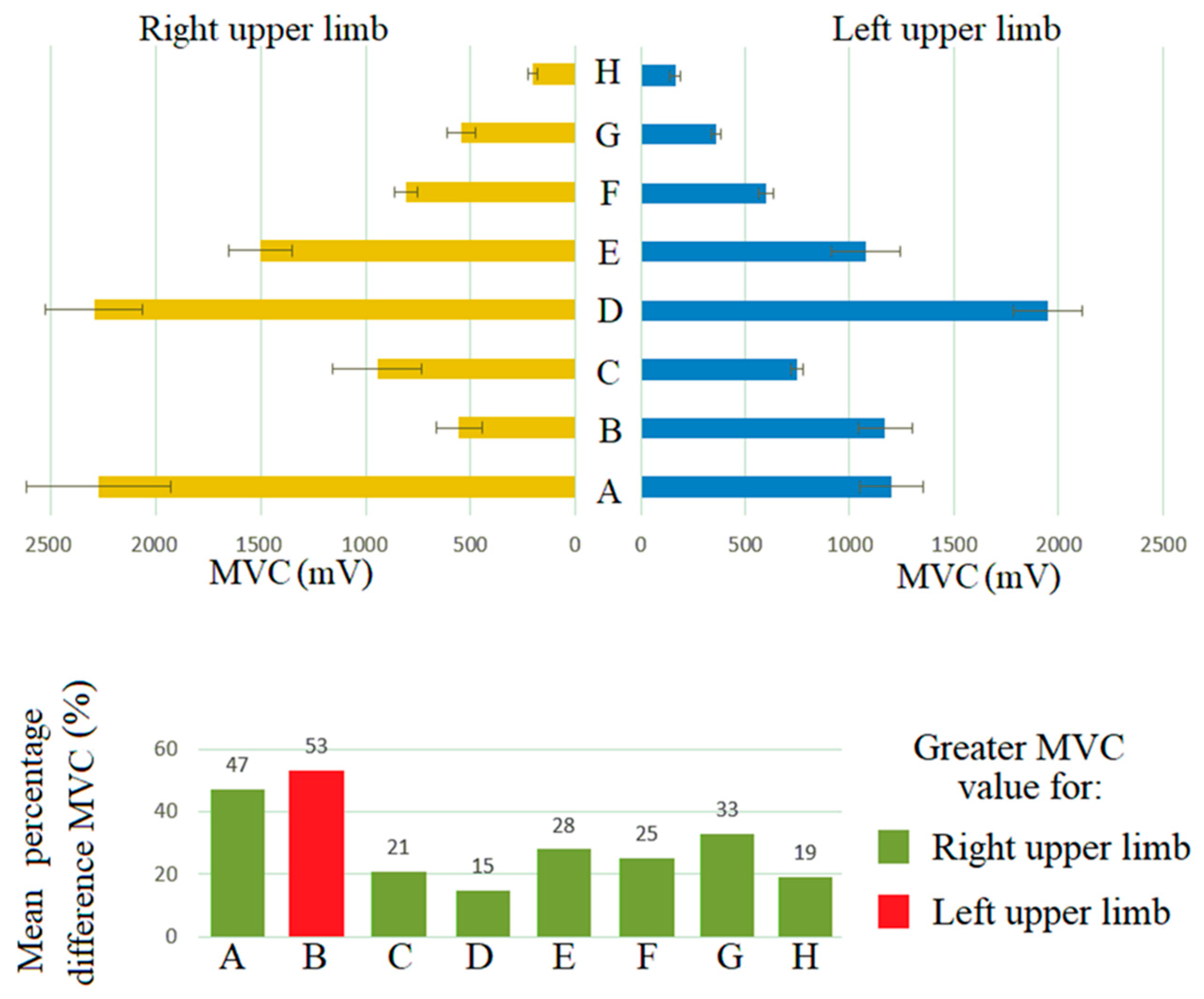
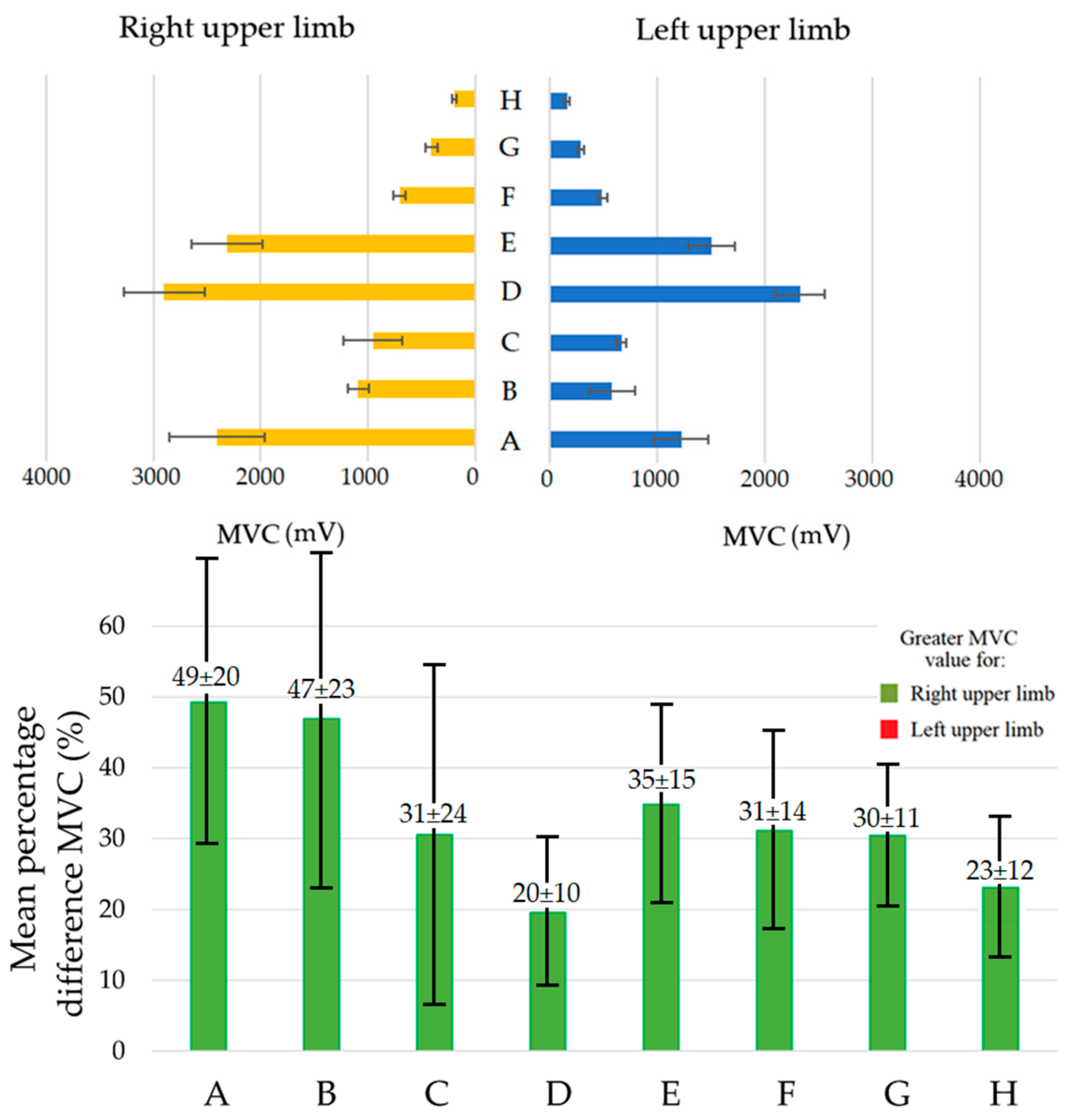
3. Results and Discussion

The maximum voluntary contraction recorded in the static standardization test differed for the left and right upper limbs (Table 2 and Table 3). Exemplary detailed results are presented for the first patient (P1) in Table 2 and Figure 1, while the summary of the results of all patients is presented as mean values (Table 3 and Figure 2). The MVC was determined for each muscle based on six measurements with a confidence level of 0.05. It can be noted that in most cases there was a higher MVC value for the muscles of the dominant upper limb (Figure 2). The research confirmed that a right-handed patient has a greater MVC in their dominant hand during exercise, which is consistent with the results of other researchers [40,41,42]. The smallest difference of MVC between the right and the left arms was recorded for muscle D; the difference did not exceed 20 ± 10% (deviation of the mean is also the smallest (Figure 2)). This muscle can be used by the control system described herein to collect control signals from the left or right upper limb. It is important that the control system uses the muscle tension signals with values that are similar for the two upper limbs. Otherwise, the measurement from a much stronger or weaker upper limb would lead to an improperly selected gear ratio or torque value. In such a situation, the assistance adjusted to the overall physical abilities of the user would be out of proportion. This pilot research has shown that muscle D generated the best control signal for such a system, but this finding should be tested in a larger group in the future.
After selecting muscle D in the control process as the one with the most favorable MVC signal, the muscle was subjected to further analysis. The purpose of this analysis was to extract the phases of the cycle involved in propelling a manually propelled wheelchair [43,44]. Two basic phases of wheelchair propulsion can be distinguished: the propelling phase (P1), with the highest muscle tension, and the return phase (P2), with a low MVC value (Figure 3). It was observed that the propelling phase time (arm movement from position 1 to 2) is shorter than the return phase (arm movement from position 2 to 3). The return phase time is the time when the system is allowed to make adjustments to the propulsion system. Such adjustment requires the development of an innovative control algorithm and a new design for the wheelchair.

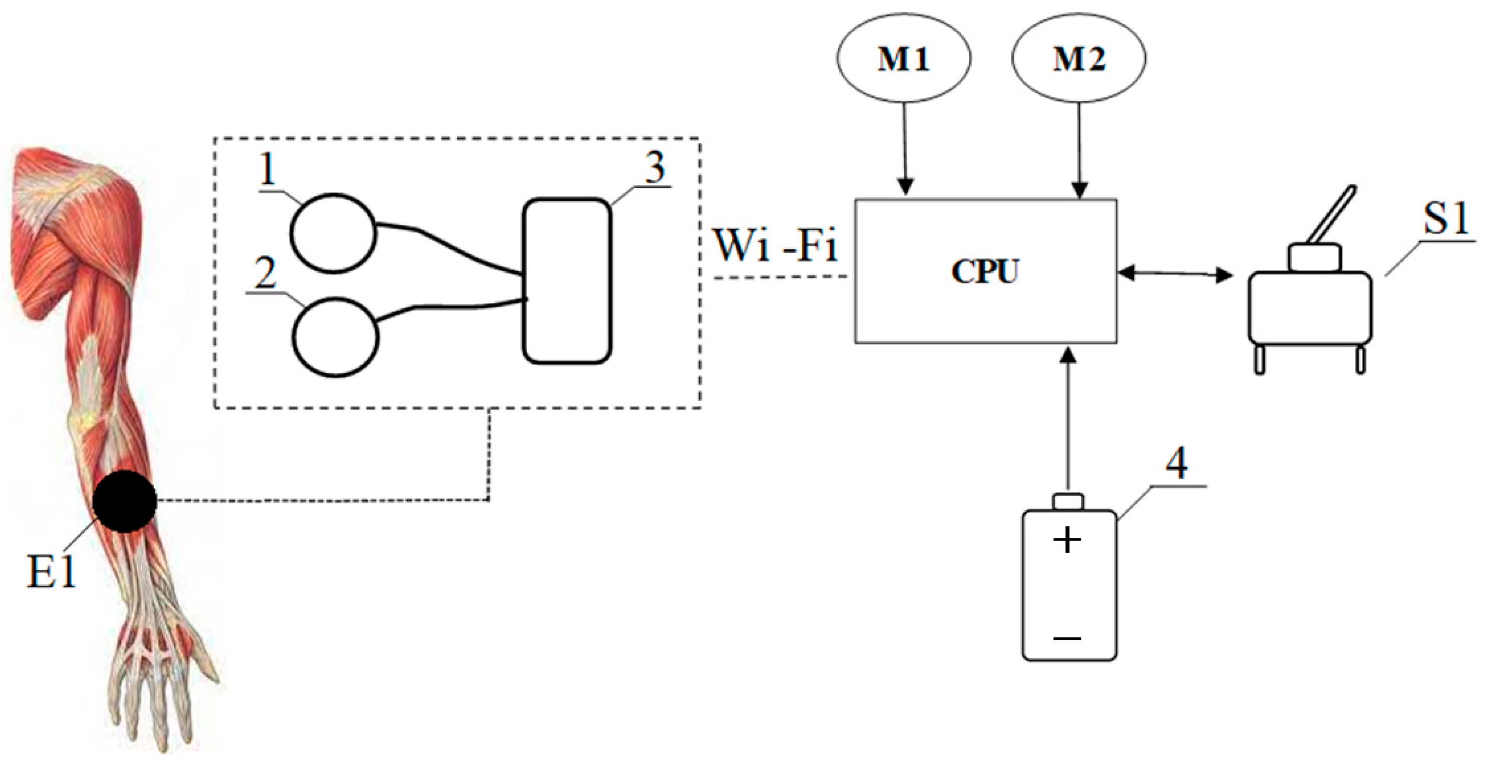
4. The Concept of an Innovative Wheelchair Design and Control Algorithm

A control system using the MA signal requires the design of a wheelchair equipped with a hybrid electric–manual propulsion system [27] or a wheelchair with a mechanical transmission gear [11,45] equipped with electrically controlled mechanisms [46,47].
The patient must undergo the maximal voluntary muscle contraction tests used in the normalization process before using the wheelchair. The contractions will allow the MVC signal, expressed in mV, to be converted into the MA control signal, expressed as a percentage of the muscle load. The average absolute value of MA is preferred over a moving average every 100 ms. The algorithm must determine the maximum extreme of the function in the propelling phase. In addition, identifying the extremum of the long radial extensor muscle of the wrist MA function allows the propelling phase and the beginning of the return phase to be distinguished. It is recommended that the program calculates the average of the two pushes in order to average the results and eliminate artefacts.
In the example arrangement, an electrode is attached to the user’s skin on the belly of the long radial extensor muscle of the wrist (E1). Each electrode consists of two active electrodes and one reference electrode with a Wi-Fi module (Figure 4). The electromyographic signal is sent to a microcontroller (CPU) via a Wi-Fi signal. A switch that enables and disables the system is connected to the microcontroller (S1). The microcontroller transmits a signal to the two motors coupled with the left (M1) and right (M2) wheels. A battery is connected to the entire system.
The control system is started using the switch (S1) (Figure 5). Then, the muscle signal recording procedure M V C e 1 is initiated. The algorithm converts the signal into a graph of muscle activity, a dimensionless quantity, on a scale from 0 to 1 M A e 1 , according to the following equations:
M V C e 1 R M S ( t i ) = i = 0 100 | M V C e 1 ( t j ) | 100   [ mV ]
M A e 1 ( t i ) = M V C e 1 R M S ( t i ) M V C m a x e 1   [ ]
where M V C e 1 is the electrical signal from the belly of the long radial extensor muscle of the wrist and   M V C m a x e 1 is the signal from the static test.
In the first step (2), the signal M V C e 1 is converted into positive values before a moving average is calculated: M V C e 1 R M S ( t i ) every one hundred measurements for time unit t j . Based on these values, the muscle activity M A e 1 is determined for a time unit t i . The time unit t i is shifted by one hundred measuring cycles in relation to the actual EMG measurement time t j .
Based on the measured signal, the algorithm determines two coefficients informing about the current phase of the propelling cycle. The first coefficient k n reflects the end of the propelling phase and is derived from the maximum of the function M A e 1 ( t i ) . The end of the return phase is also determined and marked with the symbol k p . The limit value of the   coefficient   k p is set at 0.1 M A e 1 ( t i ) . This value was adopted based on experimental studies, and it represents the value of muscle activity when the arm is extended. The values of these coefficients make it possible to determine the duration of the return phase and the propelling phase. The long radial extensor muscle of the wrist is responsible for straightening and bending the wrist, among other things. For this reason, the signal from that muscle was chosen as the signal that defines the propelling cycles.
Next, the algorithm searches for the maximum value of muscle activity M A e 1 ( t i ) during the propelling phase. The analysis is performed with one propelling cycle lag. According to the algorithm, the user defines k, which is the value of muscle activity M A e 1 , above which the muscular propelling system is supported by the additional propulsion system. It is preferable that the coefficient k is equal to 0.25 because this corresponds to 25% of the muscular system load. The value of such a load ensures the safe physical activity necessary for the process of rehabilitation. The value of k cannot be lower than k p or greater than the value of k n . It should be noted that these are only proposed values based on the analysis of one person’s electromyographic signals. The values of the coefficients k n and k p will vary depending on the successive propelling cycles, and the value of k is defined experimentally by the user based on their subjective feelings. Further research may be dedicated to defining the value of k depending on the course of the disease or the rehabilitation process. If the coefficient k n is higher than k, its value is sent to the CPU, where it is converted into a signal to control the electric motors.

5. Conclusions

The MVC signal can be used to control propulsion systems and to control the drive transmission systems. In wheelchairs, such a control signal may be used by the assistive technology systems installed in hybrid manual–electric propulsion systems or manual systems with electrically controlled transmissions. In the pilot research, it was found that a measurement of MVC for the control system from only one upper limb requires careful analysis, because the asymmetry in the mean MVC signal values of the left and right upper-limb muscles may vary from 20% to 49%. The long radial extensor muscle of the wrist provided the most similar mean MVC values for the left and right upper limbs of the test subject (about 20% difference). The research shows the possibility of using the MVC signal for innovative control systems and in systems that support movement, and not only in the systems responsible for choosing the direction. It was also confirmed that despite the asymmetry in the value of the MVC signal, the effort for the left and right limb is proportional, which confirms the possibility of the developed system working. The research provided information on the ranges of the tested values and may constitute input data for the design work of a new device and the development of an innovative control algorithm. Additionally, the concepts were presented for a system that would facilitate the movement of people with disabilities and infirmities. The limitation of the application of the presented research results and the concept of the system is the correctness of operation only in the case of selected types of disability. Some users may have selected inactive muscle groups; if this is the case, further research should be carried out to find the right muscle that enables control. Another limitation of steering precision is the change in the MVCmax signal, which may alter as a result of, e.g., an increase in physical activity or lack thereof. For the best efficiency of using the system, the standardization test should be performed at regular intervals, the more often the better, because it is an individual matter. The disadvantage of the control system is the necessity of a glued measuring electrode in the entire life cycle of the device. Inference based on these results is limited because the research was part of a pilot study and was carried out on a small sample. Future research should be extended to include more wheelchair users or should follow an individual approach to designing disability and infirm mobility systems.

6. Patents

Patent application in the Patent Office of the Republic of Poland: P.440187; date of notification: 20 January 2022; title: The method and system of controlling a wheelchair using muscle bioelectric potentials (original title in Polish: Sposób i system sterowania wózkiem inwalidzkim za pomocą potencjałów bioelektrycznych mięśni); authors: Wieczorek Bartosz, Warguła Łukasz and Marciniak Agnieszka.

Author Contributions

Conceptualisation, Ł.W. and A.M.; methodology, Ł.W. and A.M.; software, Ł.W. and A.M.; validation, Ł.W. and A.M.; formal analysis, Ł.W. and A.M.; investigation, Ł.W. and A.M.; resources, Ł.W. and A.M.; data curation, A.M. and Ł.W.; writing—original draft preparation, Ł.W. and A.M.; writing—review and editing, Ł.W. and A.M.; visualization, Ł.W. and A.M.; supervision, Ł.W.; project administration, Ł.W.; funding acquisition, Ł.W. All authors have read and agreed to the published version of the manuscript.

Funding

This research is a part of the project: “Innovative Drive Systems for Wheelchairs—Design, Prototype, Research, number: “Rzeczy są dla ludzi/0004/2020”, financed by National Centre for Research and Development, https://www.gov.pl/web/ncbr (accessed on 3 October 2021).

Institutional Review Board Statement

The study was accepted by the Bioethical Commission at Karol 97 Marcinkowski Medical University in Poznań, Poland (Resolution No. 1100/16 of 10 No-98 vember 2016, under the guidance of P. Chęciński for the research team led by B. 99 Wieczorek PhD).

Informed Consent Statement

Informed consent was obtained from all subjects involved in the study.

Data Availability Statement

Not applicable.

Conflicts of Interest

The authors declare no conflict of interest.

References

  1. Wieczorek, B.; Kukla, M.; Rybarczyk, D.; Warguła, Ł. Evaluation of the biomechanical parameters of human-wheelchair systems during ramp climbing with the use of a manual wheelchair with anti-rollback devices. Appl. Sci. 2020, 10, 8757. [Google Scholar] [CrossRef]
  2. Kilikevičius, A.; Bačinskas, D.; Selech, J.; Matijošius, J.; Kilikevičienė, K.; Vainorius, D.; Ulbrich, D.; Romek, D. The Influence of Different Loads on the Footbridge Dynamic Parameters. Symmetry 2020, 12, 657. [Google Scholar] [CrossRef]
  3. Rymaniak, Ł.; Kamińska, M.; Szymlet, N.; Grzeszczyk, R. Analysis of Harmful Exhaust Gas Concentrations in Cloud behind a Vehicle with a Spark Ignition Engine. Energies 2021, 14, 1769. [Google Scholar] [CrossRef]
  4. Gull, M.A.; Thoegersen, M.; Bengtson, S.H.; Mohammadi, M.; Andreasen Struijk, L.N.S.; Moeslund, T.B.; Bak, T.; Bai, S. A 4-DOF Upper Limb Exoskeleton for Physical Assistance: Design, Modeling, Control and Performance Evaluation. Appl. Sci. 2021, 11, 5865. [Google Scholar] [CrossRef]
  5. Kukla, M.; Wieczorek, B.; Warguła, Ł.; Górecki, J.; Giedrowicz, M. An Analytical Modelling of Demand for Driving Torque of a Wheelchair with Electromechanical Drive. Energies 2021, 14, 7315. [Google Scholar] [CrossRef]
  6. Marco-Ahulló, A.; Montesinos-Magraner, L.; Gonzalez, L.-M.; Llorens, R.; Segura-Navarro, X.; García-Massó, X. Validation of Using Smartphone Built-In Accelerometers to Estimate the Active Energy Expenditures of Full-Time Manual Wheelchair Users with Spinal Cord Injury. Sensors 2021, 21, 1498. [Google Scholar] [CrossRef]
  7. Giménez, C.V.; Krug, S.; Qureshi, F.Z.; O’Nils, M. Evaluation of 2D-/3D-Feet-Detection Methods for Semi-Autonomous Powered Wheelchair Navigation. J. Imaging 2021, 7, 255. [Google Scholar] [CrossRef]
  8. Dziewiatkowski, M.; Szpica, D.; Borawski, A. Evaluation of impact of combustion engine controller adaptation process on level of exhaust gas emissions in gasoline and compressed natural gas supply process. Eng. Rural Dev. 2020, 19, 541–548. [Google Scholar]
  9. Nikonova, T.; Zharkevich, O.; Dandybaev, E.; Baimuldin, M.; Daich, L.; Sichkarenko, A.; Kotov, E. Developing a Measuring System for Monitoring the Thickness of the 6 m Wide HDPE/LDPE Polymer Geomembrane with Its Continuous Flow Using Automation Equipment. Appl. Sci. 2021, 11, 10045. [Google Scholar] [CrossRef]
  10. Gabryelski, J.; Kurczewski, P.; Sydor, M.; Szperling, A.; Torzyński, D.; Zabłocki, M. Development of Transport for Disabled People on the Example of Wheelchair Propulsion with Cam-Thread Drive. Energies 2021, 14, 8137. [Google Scholar] [CrossRef]
  11. Wieczorek, B.; Kukla, M. Effects of the performance parameters of a wheelchair on the changes in the position of the centre of gravity of the human body in dynamic condition. PLoS ONE 2019, 14, e0226013. [Google Scholar] [CrossRef] [PubMed]
  12. Lipert, A.; Wróbel, K.; Spychała, M.; Rasmus, P.; Timler, D.; Marczak, M.; Kozłowski, R. The Effectiveness of Active Rehabilitation Camp on Physical Performance of Disabled People Moving in Wheelchairs. Int. J. Environ. Res. Public Health 2021, 18, 7572. [Google Scholar] [CrossRef] [PubMed]
  13. Sivakanthan, S.; Castagno, J.; Candiotti, J.L.; Zhou, J.; Sundaram, S.A.; Atkins, E.M.; Cooper, R.A. Automated Curb Recognition and Negotiation for Robotic Wheelchairs. Sensors 2021, 21, 7810. [Google Scholar] [CrossRef] [PubMed]
  14. Maule, L.; Luchetti, A.; Zanetti, M.; Tomasin, P.; Pertile, M.; Tavernini, M.; Guandalini, G.M.A.; De Cecco, M. RoboEye, an Efficient, Reliable and Safe Semi-Autonomous Gaze Driven Wheelchair for Domestic Use. Technologies 2021, 9, 16. [Google Scholar] [CrossRef]
  15. Wieczorek, B.; Kukla, M.; Warguła, Ł. The Symmetric Nature of the Position Distribution of the Human Body Center of Gravity during Propelling Manual Wheelchairs with Innovative Propulsion Systems. Symmetry 2021, 13, 154. [Google Scholar] [CrossRef]
  16. Sprigle, S.; Huang, M.; Misch, J. Measurement of rolling resistance and scrub torque of manual wheelchair drive wheels and casters. Assist. Technol. 2019, 34, 91–103. [Google Scholar] [CrossRef]
  17. Ott, J.; Wilson-Jene, H.; Koontz, A.; Pearlman, J. Evaluation of rolling resistance in manual wheelchair wheels and casters using drum-based testing. Disabil. Rehabil. Assist. Technol. 2020, 1–12. [Google Scholar] [CrossRef]
  18. Rietveld, T.; Mason, B.S.; Goosey-Tolfrey, V.L.; van der Woude, L.H.; de Groot, S.; Vegter, R.J. Inertial measurement units to estimate drag forces and power output during standardised wheelchair tennis coast-down and sprint tests. Sports Biomech. 2021, 1–19. [Google Scholar] [CrossRef]
  19. Lemaire, E.D.; O’Neill, P.A.; Desrosiers, M.M.; Robertson, D.G. Wheelchair ramp navigation in snow and ice-grit conditions. Arch. Phys. Med. Rehabil. 2010, 91, 1516–1523. [Google Scholar] [CrossRef]
  20. Wieczorek, B.; Kukla, M.; Warguła, Ł.; Rybarczyk, D.; Giedrowicz, M.; Górecki, J. The Impact of the Human Body Position Changes During Wheelchair Propelling on Motion Resistance Force: A Preliminary Study. J. Biomech. Eng. 2021, 143, 081008. [Google Scholar] [CrossRef]
  21. Wieczorek, B.; Kukla, M. Biomechanical Relationships Between Manual Wheelchair Steering and the Position of the Human Body’s Center of Gravity. J. Biomech. Eng. 2020, 142, 081006. [Google Scholar] [CrossRef]
  22. Zhou, H.; Hou, K.-M.; Zuo, D.; Li, J. Intelligent Urban Public Transportation for Accessibility Dedicated to People with Disabilities. Sensors 2012, 12, 10678–10692. [Google Scholar] [CrossRef] [PubMed]
  23. Morales, Y.; Watanabe, A.; Ferreri, F.; Even, J.; Shinozawa, K.; Hagita, N. Passenger discomfort map for autonomous navigation in a robotic wheelchair. Robot. Auton. Syst. 2018, 103, 13–26. [Google Scholar] [CrossRef]
  24. Rousseau-Harrison, K.; Rochette, A.; Routhier, F.; Dessureault, D.; Thibault, F.; Côté, O. Impact of wheelchair acquisition on social participation. Disabil. Rehabil. Assist. Technol. 2009, 4, 344–352. [Google Scholar] [CrossRef]
  25. Wong, M.C.S.; Yap, R.C.Y. Social Impact Investing for Marginalized Communities in Hong Kong: Cases and Issues. Sustainability 2019, 11, 2831. [Google Scholar] [CrossRef] [Green Version]
  26. Van der Woude, L.H.; De Groot, S.; Janssen, T.W. Manual wheelchairs: Research and innovation in rehabilitation, sports, daily life and health. Med. Eng. Phys. 2006, 28, 905–915. [Google Scholar] [CrossRef] [PubMed]
  27. Wieczorek, B.; Warguła, Ł.; Rybarczyk, D. Impact of a Hybrid Assisted Wheelchair Propulsion System on Motion Kinematics during Climbing up a Slope. Appl. Sci. 2020, 10, 1025. [Google Scholar] [CrossRef] [Green Version]
  28. Oh, S.; Hori, Y. Disturbance attenuation control for power-assist wheelchair operation on slopes. IEEE Trans. Control Syst. Technol. 2013, 22, 828–837. [Google Scholar]
  29. Oh, S.; Kong, K.; Hori, Y. Operation state observation and condition recognition for the control of power-assisted wheelchair. Mechatronics 2014, 24, 1101–1111. [Google Scholar] [CrossRef]
  30. Jones, B.; Menaro, A.; Sparkman, J. Electromyographic Controlled Vehicles and Chairs. US Patent 10426370B2, 1 November 2019. [Google Scholar]
  31. Kim, D.; Lee, H. Powered Wheelchair Interface Method for the Spinal Cord Injury Person. Korea Patent 100488684B1, 11 May 2005. [Google Scholar]
  32. Callejas-Cuervo, M.; González-Cely, A.X.; Bastos-Filho, T. Control systems and electronic instrumentation applied to autonomy in wheelchair mobility: The state of the art. Sensors 2020, 20, 6326. [Google Scholar] [CrossRef] [PubMed]
  33. Jang, G.; Kim, J.; Lee, S.; Choi, Y. EMG-Based Continuous Control Scheme with Simple Classifier for Electric-Powered Wheelchair. IEEE Trans. Ind. Electron. 2016, 63, 3695–3705. [Google Scholar] [CrossRef]
  34. Jang, G.; Choi, Y. EMG-based continuous control method for electric wheelchair. In Proceedings of the International Conference on Intelligence Robots and Systems (IEEE/RSJ 2014), Chicago, IL, USA, 14–18 September 2014; pp. 3549–3554. [Google Scholar]
  35. Küçükyildiz, G.; Ocak, H.; Şayli, Ö.; Karakaya, S. Real time control of a wheelchair based on EMG and Kinect for the disabled people. In Proceedings of the Medical Technologies National Conference (TIPTEKNO 2015), Bodrum, Turkey, 15–18 October 2015; pp. 1–4. [Google Scholar]
  36. Kaur, A. Wheelchair control for disabled patients using EMG/EOG based human machine interface: A review. J. Med. Eng. Technol. 2021, 45, 61–74. [Google Scholar] [CrossRef] [PubMed]
  37. Miller, A.; Norfleet, D.A. “Wheelchair Fatigue Reducer”. Chancellor’s Honors Program Projects. 2016. Available online: https://trace.tennessee.edu/utk_chanhonoproj/1952 (accessed on 13 February 2022).
  38. Zukowski, L.A.; Hass, C.J.; Shechtman, O.; Christou, E.A.; Tillman, M.D. The effect of wheelchair propulsion style on changes in time spent in extreme wrist orientations after a bout of fatiguing propulsion. Ergonomics 2017, 60, 1425–1434. [Google Scholar] [CrossRef]
  39. Guo, L.Y.; Su, F.C.; Wu, H.W.; An, K.N. Mechanical energy and power flow of the upper extremity in manual wheelchair propulsion. Clin. Biomech. 2003, 18, 106–114. [Google Scholar] [CrossRef]
  40. Wang, Y.; Choi, J.; Loh, P.Y.; Muraki, S. A comparison of motor control characteristics of the dominant and non-dominant arms in response to assistive force during unilateral task. Isokinet. Exerc. Sci. 2019, 27, 313–324. [Google Scholar] [CrossRef]
  41. Priya, S.; Rai, M.; Joseph, D.K. Comparison between Handgrip Strength Measurement of Dominant Hand and Non Dominant Hand in Basketball Players. Indian J. Physiother. Occup. Ther. 2018, 12, 126–130. [Google Scholar] [CrossRef]
  42. Yuine, H.; Yoshii, Y.; Iwai, K.; Ishii, T.; Shiraishi, H. Assessment of distal radioulnar joint stabilityin healthy subjects: Changes with dominant hand, sex, andage. J. Orthop. Res. 2021, 39, 2028–2035. [Google Scholar] [CrossRef]
  43. Madansingh, S.I.; Fortune, E.; Morrow, M.M.; Zhao, K.D.; Cloud-Biebl, B.A. Comparing supraspinatus to acromion proximity and kinematics of the shoulder and thorax between manual wheelchair propulsion styles: A pilot study. Clin. Biomech. 2020, 74, 42–50. [Google Scholar] [CrossRef]
  44. Briley, S.J.; Vegter, R.J.; Goosey-Tolfrey, V.L.; Mason, B.S. Scapular kinematic variability during wheelchair propulsion is associated with shoulder pain in wheelchair users. J. Biomech. 2020, 113, 110099. [Google Scholar] [CrossRef]
  45. Sasaki, M.; Ota, Y.; Hase, K.; Stefanov, D.; Yamaguchi, M. Simulation model of a lever-propelled wheelchair. In Proceedings of the 2014 36th Annual International Conference of the IEEE Engineering in Medicine and Biology Society, Chicago, IL, USA, 26–30 August 2014; pp. 6923–6926. [Google Scholar]
  46. Yu, C.H.; Tseng, C.Y. Research on gear-change control technology for the clutchless automatic–manual transmission of an electric vehicle. Proc. Inst. Mech. Eng. Part D J. Automob. Eng. 2013, 227, 1446–1458. [Google Scholar] [CrossRef]
  47. Hung, N.B.; Sung, J.; Lim, O. A simulation and experimental study of operating performance of an electric bicycle integrated with a semi-automatic transmission. Appl. Energy 2018, 221, 319–333. [Google Scholar] [CrossRef]
Figure 1. Maximum voluntary contraction asymmetry for the left and right upper limbs (patient 1 (P1)), where A—biceps; B—triceps; C—middle deltoid muscle; D—long extensor muscle of the wrist; E—deltoid anterior head; F—deltoid posterior head; G—trapezius muscle; H—subcapsular muscle. The mean MVC value was determined with the confidence interval for the probability level p = 0.05.
Symmetry 14 01002 g001
Figure 2. Mean maximum voluntary contraction asymmetry for the left and right upper limbs for all patients, where A—biceps; B—triceps; C—middle deltoid muscle; D—long extensor muscle of the wrist; E—deltoid anterior head; F—deltoid posterior head; G—trapezius muscle; H—subcapsular muscle. The mean MVC value was determined with the confidence interval for the probability level p = 0.05.
Symmetry 14 01002 g002
Figure 3. The MVC characteristics as a function of time when propelling a wheelchair forward on a flat hard surface.
Symmetry 14 01002 g003
Figure 4. Control system components: 1 and 2—active electrodes; 3—reference electrode; 4—battery; E1—electrode attachment point on the belly of the long radial extensor muscle of the wrist; M1 and M2—electric motors; S1—switches and the system’s main switch.
Symmetry 14 01002 g004
Figure 5. Schematic of the control system.
Symmetry 14 01002 g005
Table 1. Presentation of anthropometric features, the level of experience in an operating wheelchair, and the region of spinal cord injury for the test subjects.
PatientGenderHeightWeightAgeDominant HandPush ForceExperienceRegion of Spinal Cord Injury
cmkgYears-N--
P1male1839032right364■■■■□lumbar
P2male1716725right282■■■■■sacral
P3male1697230right263■■■□□sacral
P4male1857236right321■■□□□lumbar
P5male1798832right321■■■■□lumbar
P6male1887436right291■□□□□lumbar
P7male1738731right296■■□□□sacral
P8male1748135right247■■■■□sacral
P9male17511031right333■■■■□lumbar
P10male18310032right329■■■□□sacral
Table 2. MVC values during the process of propelling a wheelchair for patient 1 (P1). The mean MVC value was determined with the confidence interval for the probability level p = 0.05.
MuscleLimbMeasurement TestMean MVC
123456
mVmV
Biceps muscle (A)R1883.02061.02039.02395.02537.02721.02272.67 ± 343.95
L1417.01356.01116.01096.01101.01111.01199.5 ± 153.53
Triceps muscle (B)R687.9589.7384.7522.5625.0513.6553.9 ± 110.6
L1086.01069.01100.01110.01344.01321.01171.67 ± 131.76
Deltoid middle head muscle (C)R1202.01132.0890.2982.8720.0724.5941.92 ± 212.31
L744.5780.5758.7744.4768.3697.3748.95 ± 30.32
Long extensor muscle of the wrist (D)R2128.02137.02115.02292.02676.02423.02295.17 ± 233.16
L1769.01837.01942.01881.02110.02162.01950.17 ± 163.19
Deltoid front head muscle (E)R1369.01530.01376.01567.01743.01426.01501.83 ± 150.21
L1294.01119.0915.1896.81169.01078.01078.65 ± 163.19
Deltoid back head muscle (E)R865.3787.6789.3789.7868.0731.2805.18 ± 55.2
L586.3565.7651.3619.1574.2606.2600.47 ± 33.40
Trapezius muscle (G)R634.9553.1569.9547.4450.3489.1540.78 ± 67.62
L341.5341.4385.2367.1343.1387.9361.03 ± 23.14
Subcapsular muscle (H)R190.2188.7194.7187.2238.5225.6204.15 ± 23.23
L157.5147.1145.9147.7193.7204.0165.98 ± 27.28
Table 3. Mean MVC values during the process of propelling a wheelchair for all patients. The mean MVC value was determined with the confidence interval for the probability level p = 0.05.
MuscleLimbPatientMean
MVC
12345678910
mVmV
Biceps muscle (A)R2273 ± 3441958 ± 3272447 ± 4132156 ± 3102283 ± 3113265 ± 4132679 ± 4472141 ± 3612994 ± 4301903 ± 2582410 ± 445
L1200 ± 1541356 ± 1541228 ± 1691206 ± 169881 ± 1231167 ± 1611763 ± 2001395 ± 1921151 ± 161881 ± 1231223 ± 254
Triceps muscle (B)R554 ± 1111058 ± 100935 ± 1091232 ± 1331196 ± 941506 ± 122855 ± 981001 ± 1001066 ± 971478 ± 1131088 ± 95
L1172 ± 132531 ± 341381 ± 292627 ± 382531 ± 306565 ± 392525 ± 275346 ± 313460 ± 330638 ± 378577 ± 215
Deltoid middle head muscle (C)R942 ± 2121064 ± 144926 ± 160826 ± 129677 ± 144898 ± 1901517 ± 206926 ± 1601219 ± 190533 ± 114953 ± 274
L749 ± 30695 ± 98645 ± 94663 ± 98684 ± 98621 ± 98624 ± 88615 ± 90640 ± 95684 ± 98662 ± 42
Long extensor muscle of the wrist (D)R2295 ± 2332992 ± 4822538 ± 4132796 ± 4203613 ± 4642956 ± 4202650 ± 4262834 ± 4613025 ± 4543291 ± 4232899 ± 375
L1950 ± 1632223 ± 1862194 ± 1732276 ± 1862743 ± 2002486 ± 1772113 ± 1772428 ± 1922408 ± 1972490 ± 1812331 ± 226
Deltoid front head muscle (E)R1502 ± 1502494 ± 1802133 ± 1712413 ± 1702597 ± 1652367 ± 1842219 ± 1602298 ± 1852413 ± 1702702 ± 1712314 ± 331
L1079 ± 1631779 ± 5471382 ± 5191372 ± 5261637 ± 4821692 ± 5401567 ± 4821482 ± 5571345 ± 5161742 ± 5121508 ± 218
Deltoid back head muscle (E)R805 ± 55709 ± 138671 ± 131695 ± 135738 ± 131600 ± 126701 ± 137679 ± 132655 ± 127764 ± 135702 ± 58
L600 ± 33441 ± 86502 ± 85489 ± 87448 ± 86467 ± 85436 ± 85515 ± 87483 ± 86454 ± 87483 ± 49
Trapezius muscle (G)R541 ± 68431 ± 268399 ± 241405 ± 255342 ± 261377 ± 265404 ± 251422 ± 255411 ± 258333 ± 255406 ± 57
L361 ± 23263 ± 118273 ± 109264 ± 111264 ± 118303 ± 120259 ± 117289 ± 115290 ± 121261 ± 117283 ± 31
Subcapsular muscle (H)R204 ± 23175 ± 103179 ± 102170 ± 101229 ± 106212 ± 104179 ± 105181 ± 103172 ± 102229 ± 106193 ± 23
L166 ± 27134 ± 313136 ± 320139 ± 323184 ± 327202 ± 341146 ± 341137 ± 323142 ± 330190 ± 337157 ± 26
Publisher’s Note: MDPI stays neutral with regard to jurisdictional claims in published maps and institutional affiliations.

