
Post-Processing of 3D-Printed Polymers
by
 ,
,
John Ryan C. Dizon
1,2,* ,
,
Ciara Catherine L. Gache
2,
Honelly Mae S. Cascolan
3,
Lina T. Cancino
4 and
Rigoberto C. Advincula
5,6,7 1
DR3AM Center, Bataan Peninsula State University, City of Balanga 2100, Philippines
2
Department of Industrial Engineering, College of Engineering and Architecture, Bataan Peninsula State University, City of Balanga 2100, Philippines
3
Secondary Education Department, College of Education, Pangasinan State University, Asingan 2439, Philippines
4
Natural Science Department, College of Arts, Sciences and Letters, Lingayen Campus, Pangasinan State University, Lingayen 2401, Philippines
5
Department of Chemical and Biomolecular Engineering and Joint Institute for Advanced Materials, University of Tennessee, Knoxville, TN 37996, USA
6
Center for Nanophase Materials and Sciences (CNMS), Oak Ridge National Laboratory, Oak Ridge, TN 37830, USA
7
Department of Macromolecular Science and Engineering, Case Western Reserve University, Cleveland, OH 44106, USA
*
Author to whom correspondence should be addressed.
Technologies 2021, 9(3), 61; https://0-doi-org.brum.beds.ac.uk/10.3390/technologies9030061
Submission received: 19 June 2021
/
Revised: 2 August 2021
/
Accepted: 3 August 2021
/
Published: 25 August 2021
(This article belongs to the Special Issue 3D Printing and Additive Manufacturing: Principles and Applications)
Abstract
:Additive manufacturing, commonly known as 3D printing, is an advancement over traditional formative manufacturing methods. It can increase efficiency in manufacturing operations highlighting advantages such as rapid prototyping, reduction of waste, reduction of manufacturing time and cost, and increased flexibility in a production setting. The additive manufacturing (AM) process consists of five steps: (1) preparation of 3D models for printing (designing the part/object), (2) conversion to STL file, (3) slicing and setting of 3D printing parameters, (4) actual printing, and (5) finishing/post-processing methods. Very often, the 3D printed part is sufficient by itself without further post-printing processing. However, many applications still require some forms of post-processing, especially those for industrial applications. This review focuses on the importance of different finishing/post-processing methods for 3D-printed polymers. Different 3D printing technologies and materials are considered in presenting the authors’ perspective. The advantages and disadvantages of using these methods are also discussed together with the cost and time in doing the post-processing activities. Lastly, this review also includes discussions on the enhancement of properties such as electrical, mechanical, and chemical, and other characteristics such as geometrical precision, durability, surface properties, and aesthetic value with post-printing processing. Future perspectives is also provided towards the end of this review.
1. Introduction
Additive manufacturing (AM), also known as 3D printing, is playing an increasingly important role in industrial manufacturing and is mainly used in prototyping and tool making. Its technological advances are bringing about new design possibilities, products, and production paradigms [1]. According to a survey on more than 300 companies about the concept of 3D printing, most agree that the adaption of AM has already started changing the face of manufacturing, with respondents indicating that over 80% are using it for new purposes, ~70% are using it for prototyping, and over 90% indicated a positive outlook on the way future industries will think and operate [2].
Recently, competitive and low-cost AM methods have been studied, which can, at the same time, produce high print qualities. Innovators can now easily think and form 3D ideas as AM/printing significantly simplifies prototype production [3]. Moreover, because of its additive nature, or by printing through adding one layer at a time, it provides the capability to create unique components that cannot be replicated via subtractive manufacturing (SM) techniques, such as machining. Products produced via AM also demonstrated more precise physical dimensions, especially in complex designs [4].
AM empowers the production of lightweight products that have a transformative approach to industrial production. AM technologies are applied in diverse fields of technological applications that often improve existing designs and properties [5,6,7]. Moreover, 3D printing is increasingly being used in high performance and high throughput industrial applications, namely rapid prototyping, rapid tooling, rapid manufacturing [3,5,8], advanced electronics [9], health-related applications [10], water filtration [11,12], gas sensing [13], and many others [14,15,16,17,18,19,20,21,22,23]. This demands and warrants the technology to consistently and reliably deliver high-quality parts with the properties needed to meet real and demanding applications. These include ensuring the performance of the materials used, establishing process control, and reducing human error [24,25,26,27,28,29,30]. Three-dimensional printing can be used in the creation of larger parts, building complex geometries, and consolidating multiple part components. It may also be used to design a combined form, fit, and function in a single part [31]. Finally, 3D-printed products and prototypes are not only assessed from the above-mentioned applications and qualities, but also for its aesthetic value.
Post-processing includes all of the processes that are performed after the parts are removed from a 3D printer. Post-processing has two categories, which are (1) primary and (2) secondary. Primary processes include the necessary steps that must be done on all 3D-printed parts to make them suitable to be used in any particular application. Secondary post-processing includes optional parts finishing that improves the properties, performance/functions, or even the aesthetics of the part [32]. Primary post-processing activities generally include the removal of support as well as cleaning, while secondary post-processing activities are those that are not necessary/essential but would depend on the needs and purposes of the user, such as painting and vapor smoothing. Beyond this classification, the necessity will eventually be defined by the form, fit, and function. Wetting, gloss, scratch resistance, chemical resistance, heat resistance or thermal shielding, electromagnetic shielding, and others may be obtained by ex situ physical or chemical methods, including the application of another layer of material or coating. Another possible function of post-processing is to elicit stimuli-responsive properties such as in 4D printing [33,34,35].
Finishing/post-processing plays a significant role in improving both mechanical/chemical and aesthetic properties, meeting tight tolerances, providing near injection molded finishes, and achieving added durability [7,9,31]. It enables the delivery of a product with a maximum possible value and impact, as it creates aesthetic effects while improving mechanical, geometric, and other high-value properties. For one example, it improves the surface properties of prints beyond the initial print such that it controls wetting behavior, gloss, scratch resistance, and other properties. These essential surface characteristics allow post-processing to significantly extend the number of applications and use-cases in many industries [36,37].
The need for post-processing depends on the printing technology, materials used, and print settings [36]. This review summarizes different post-processing techniques used on 3D-printed polymer parts while considering factors such as the printing technology, materials used, and print settings. For instance, stereolithography (SLA) uses post-processing options such as basic support removal, washing, wet sanding, and mineral oil finish, which differs from common methods used by selective layer sintering (SLS) that includes standard finish, dyeing, and metal coating, while the fused deposition modeling (FDM) technology commonly uses post-processing techniques such as support removal, sanding, and gap filling [38]. An underlying need for this is to improve thermo-mechanical properties such as annealing, UV curing, thermal exposure, and vacuum drying.
This paper summarizes the purposes as well as assesses the advantages and disadvantages of each post-processing technique, along with the procedures and methods performed, up to the aesthetic functions of 3D-printed materials. Details are also provided regarding the time and labor cost using the process, which surveys the most efficient post-processing technique for each 3D printing technology and materials. A short section on the future prospects, focusing on the methods, types of materials, part dimension, properties, quality, and safety, is also included.
Relevant information was gathered related to the post-processing of 3d-printed polymers. Keyword search has been used in different scientific journal databases and other online sources. The following keywords were used for the search such for example [[3D printing AND post-processing AND polymers]] or [[additive manufacturing AND post-processing AND polymers]]. Other more specific keywords have also been used. Initial scanning of obtained references was performed. Only relevant papers related to the post-processing of 3d-printed polymers were included, and irrelevant papers were excluded. And then, the selected papers were analyzed and synthesized.
2. Additive Manufacturing (AM) Overview
AM technology has gone through a series of innovations throughout the years. Three-dimensional printed aircraft parts and bio-printed organs are produced through collective imaginations [39]. In this process, in order to achieve the intended form of the part, fabrication is achieved through the layer by layer printing of parts [40]. Producing a digital model using computer-aided design (CAD), or via the 3D scanning of a physical model, is the first step in additive manufacturing, then the file is converted into an additive manufacturing format (AMF) or a standard tessellation language file (STL). Once the STL file is produced, it is directed to the slicing software (slicer). The data file is sliced into several (hundreds or thousands) layers and printing parameters are set using appropriate software, which is transferred to the additive manufacturing system (aka the 3D printer). The object is then manufactured (printed) layer by layer using the 3D printer. Figure 1 shows the 3D printing process/workflow [11]. After 3D printing, the object is removed from the build platform, and then post-processing, such as washing, curing, cleaning, polishing, and painting may be applied. This final step is usually not being given the needed attention/consideration.
History
Charles W. Hull first successfully 3D printed a teacup in 1983 when he invented the stereolithography (SL) additive manufacturing process. After three years (1986), at the University of Texas, Carl Deckard invented selective sintering (SS). Two years later, in 1988, at Helisys, Michael Feygin invented laminated manufacturing (LM). In 1989, Scott S. Crump discovered fused deposition modelling (FDM) at Stratasys, Inc. Also in the same year, 1989, Emanuel M. Sachs invented the three-dimensional printing (3DP) technique at the Massachusetts Institute of Technology [41]. Commercial Selective Laser Sintering was released in 1990 for the first time and, at the end of the 20th century, the bio-printer was invented. The first 3D-printed kidney was produced using biomaterial. In 2000, a 3D printer kit was launched in the market for the first time. Now, large-scale printers can print massive 3D objects. Three-dimensional printing may be utilized to print almost anything [42]. With an increasing number of patented designs, additive manufacturing is an innovation that shall enable the fourth industrial revolution [41].
3. Review of Common 3D Printing Technologies
It is important to refresh the different methods of AM as it is not always expedient to assume familiarity to appreciate the review. AM technologies for polymers have gone through a series of evolutions in the past several years. This technology therefore has a tendency to be rapidly applied in various industries, research laboratories, and, more importantly, in everyday life [43].
3.1. Material Extrusion
Material extrusion utilizes mostly thermoplastic materials as a filament. The principle is similar to a glue gun, wherein the material is added to the object from the extruder. The technology for material extrusion is fused filament fabrication (FFF) or fused deposition modeling (FDM is a trademark of Stratasys), wherein the material is heated (until flowing temperature) and added layer by layer to the object being built. Each new layer must be supported by the layer beneath it. If the model has an overhang, which is a layer not supported by anything below, there is a need to add a 3D printing support structure to ensure a successful print [44].
Common materials being used for material extrusion include acrylonitrile butadiene styrene (ABS), polycarbonate (PC), polyetherimide, polylactic acid (PLA), and nylon [45]. It is possible that precursor materials extruded as viscoelastic formulations will be extruded and cured in situ or ex situ to result in a final print. This belongs to a sub-category of 3D printing methods more commonly known as direct ink writing (DIW) or also known as viscous solution printing (VSP), but may not necessarily utilize polymer materials. However, a number of thermosets, thermoset elastomers, and plastisols (solutions of thermoplastics) can be printed in this manner [29,46,47].
3.2. Vat Photopolymerization
The stereolithography process employs the principle of photo-polymerization to produce 3D objects using a UV-sensitive resin [48,49]. It uses a high-powered laser to harden liquid resin contained in a reservoir to create the desired three-dimensional shape [50]. This is a process wherein the liquid photopolymer formulation (monomers, crosslinkers, initiators, etc.) in a tank undergoes curing by light polymerization. The technologies for vat photopolymerization include digital light processing (DLP), stereolithography (SLA), and others [45].
SLA 3D printing is known for its ability to produce high-accuracy, high resolution, watertight, and isotropic objects using different types of advanced materials with smooth surface finish and fine features [51] It uses a thermoset resin that is reactive to light. When these resins are exposed to light (of certain wavelengths), short molecular chains join together, polymerizing oligomers and monomers into solidified flexible or rigid geometries [50].
3.3. Powder Bed Fusion (PBF)
This is a process wherein a 3D object is produced with the use of a high-energy heat source to consolidate/fuse powder material. The technologies for powder bed fusion include selective laser sintering (SLS), electron beam melting (EBM), direct metal laser sintering (DMLS), and selective laser melting (SLM). PBF uses the materials such as nylon, polyetherether ketone (PEEK), thermoplastic polyurethane (TPU), and beyond polymers, metals such as titanium, nickel alloy, aluminum, carbon-filled nylon, and cobalt-chrome [45,52].
SLS is a popular 3D printing technology for industrial applications, it has been gradually maturing into a technology capable of short production runs of functional polymeric materials. SLS fuses the particles of a polymer powder by selectively sintering them using a laser, building the part layer by layer [53].
3.4. Material Jetting
The operation of material jetting is like 2D printers but in material jetting the building of part is layer by layer through a droplet of a photosensitive material that is dispensed by a print head under UV light. The technology used for material jetting includes material jetting (MJ), drop-on-demand (DOD), and nano particle jetting (NPJ). The materials usually used are ceramics, wax, stainless steel, and multi-color printing material [45].
3.5. Binder Jetting
It is a process and technology wherein binder and powder-based materials are used. A liquid binding agent (glue) is deposited into a thin layer of powder particles such as ceramics, sand, metal or composites to build the parts. An object is produced layer by layer as the binder is deposited into a powder bed to form a solid object [54]. The binder binds the powder layer together [55]. The materials used in binder jetting include sand, metal, silica, ceramics, and polymers in granular form [45].
4. Commonly-Used 3D Printing Materials
While engineers focused on improving AM methods and equipment function, applications of different 3D printing technologies by scientific research communities have evolved on developing the best 3D printing materials. For 3D printing of polymers, important considerations include thermo-mechanical properties, reactivity (or stability), stimuli-responsiveness, and hybrid materials. For practical considerations: parts durability, strength, price, abundance, and safety to humans, animals, and the environment have been emphasized. To date, several polymer materials such as thermoplastic materials including polylactic acid (PLA), acrylonitrile butadiene styrene (ABS), polyether ether ketone (PEEK), and polyethylene terephthalate glycol (PETG), are widely used. Thermosets and elastomer materials for 3D printing typically come in more formulated starting materials such as acrylates. These materials may be used in different forms, such as filaments, liquid resins, powders, etc. The following discussions focus on the common and widely known polymer materials used for 3D-Printing and are not meant to be exhaustive. Fundamental discussions on the composition, processing and properties of these commonly-used 3d printing materials would be important when determining the post-processing methods to be employed.
4.1. Acrylonitrile Butadiene Styrene (ABS)
ABS is one of the most frequently used thermoplastic materials of the 3D printing technology especially via FDM [56]. The three components in ABS are as follows: acrylonitrile which provides impact resistance and chemical resistance; butadiene which gives impact resistance and toughness; and styrene which helps in making the post-processing easy and provides rigidity [56]. It is an amorphous material, hard, rigid, and has great resistance to abrasion [57]. Just like other polymer materials, ABS melts during heating, solidifies when cooled which can be remolded or reshaped at a specific temperature, and is a very suitable polymer for FDM [58]. Other physical properties (thermal, mechanical, etc.) of the ABS material are detailed in previous studies by several research groups [3,56,59]. The use of ABS emits hazardous fumes during printing requiring proper handling and a well-ventilated area [59]. Some examples of 3D printing applications of ABS material include dashboards, wheel covers, and automotive body parts. It could also be used in the body of appliances such as telephone sets, vacuum cleaners and cameras. It is also applicable to be used in medical equipment [60]. The chemical structure of ABS could be found elsewhere [61].
4.2. Polylactic Acid or PLA
Polylactic acid or PLA is a biodegradable thermoplastic polymer material [62,63]. It is an aliphatic polyester derived from lactic acid (animals and plants sources) making it a non-toxic and more environment-friendly material and is used for making films, fibers, and bottles [64]. PLA has good mechanical properties and can substitute for petroleum-based plastics due to its biodegradability [65]. One of the major benefits for 3D printing is its low melting point compared with ABS and polyamides [66]. PLA is also important in medical technologies because of its biocompatibility. It is also a good material for disposable food packaging due to its biodegradability [67]. Other important physical properties (including thermal and mechanical) of the PLA material are detailed in previous studies [3,59,68,69]. PLA has low thermal resistance and brittleness, properties which restrict its applications compared to ABS [70]. Its biodegradable property, however, gives a more important case for it to be used in numerous biomedical applications such as bone fixation, drug delivery microsphere, and tissue engineering [71]. The chemical structure of PLA could be found elsewhere [72].
4.3. Polycarbonate or PC
Polycarbonate (PC) is another material that is widely used in the 3D printing industry. It is used for its important properties like transparency and impact resistance [73]. Due to its high strength, it has the potential to be used in tough environments and can be applied for engineering applications. PC has a high deflection temperature, enabling it to retain its structural integrity at higher temperatures but can also be bent without breaking [74]. It is widely used as an engineering thermoplastic because of its very good dimensional stability, excellent toughness and transparency [75]. The physical properties (including thermal and mechanical) of PC material are detailed in previous studies [3,76,77]. It also has some disadvantages in that it can cause problems or errors during the printing process. PC requires high temperatures to extrude properly, it is also prone to warping and shrinkage and it absorbs moisture. It is much flexible and durable than PLA but lower in flexibility and durability than Nylon. However, PC is harder than ABS and PLA, but lighter and has lower density than ABS. Also, it has better torsional strength as compared with other thermoplastics. Furthermore, it is flexible and machinable (for SM) at room temperature [78]. The chemical structure of Polycarbonate could be found elsewhere [79].
4.4. Polyethylene Terephthalate Glycol (PETG)
This material is a thermoplastic polyester (C10H8O4)n made through copolymerization of polyethylene terephthalate (PET) and ethylene glycol. PETG is widely known and used because of its characteristics such as transparency, biocompatibility, recyclability, high impact and chemical resistance. But it is also known for its weakness due to poor performance against scratching and frictional contact with a low resistance to ultraviolet (UV) light [80]. This material is widely suitable for food and chemical packaging because of its chemical resistance, good mechanical property, and because of its high transparency from its low crystalline phase [81]. The physical properties (including thermal and mechanical) of PETG material are detailed in previous studies [80,81]. Some disadvantages in 3D printing PETG include: (1) shrinkage and deformation while the printed specimen cools down [82], (2) difficulties have been encountered in achieving a constant melt flow producing a distinct texture of 3D-printed parts, (3) PETG requires a high temperature above 230 °C for its FDM processing printability. Nevertheless, it is still widely used for fabrication due to its positive characteristics like biocompatibility, recyclability, and other characteristics mentioned above. The chemical structure of PETG could be found elsewhere [83].
4.5. Polyether Ether Ketone or PEEK
The popularity of thermoplastics that are considered as high-performance or known as high-performance thermoplastics (HPTPs) is increasing. These are alternative materials for thermoset epoxy carbon fiber reinforced composite systems because of their improved and advanced properties. One example of this HPTP resin that is utilized in fabrication is Polyether ether ketone (PEEK) [84]. PEEK is a thermoplastic polymer that is utilized in the fabrication of thermally resistant parts (automotive, aerospace, OEM parts, etc.) but also in the field of dentistry. Other physical properties of PEEK were previously reported [85]. PEEK has been utilized in various insulation and structural applications due to its high temperature in the melting process and high resistance to chemicals and at the same time, it crystallizes rapidly above the glass transition temperature [86]. This polymer has semi-crystalline characteristics. This material also presents a high resistance to aggressive chemical environments as well as high toughness, rigidity, and strength. It is foreseeable that PEEK has a promising role in more extreme engineering applications and in the original equipment manufacturer (OEM) parts fabrication industry [87]. This polymer is suitable in the insulation of cable, monofilaments, molded parts, coating, and is also favorable for high strength composites [87]. Even in the field of medicine, PEEK can be used for dental implants. This is also a good material for fixed or removable prosthesis or bone replacement because its mechanical and physical properties are similar to bone [88]. The chemical structure of PEEK could be found elsewhere [89].
4.6. Nylon or Polyamide
A material that is becoming increasingly important in 3D-Printing is polyamide (PA) popularly known as nylon. Nylon has characteristics of high tensile strength, excellent tribological properties, and good elasticity. However, the printed material has some moisture sensitivity [90]. This thermoplastic is available in filament or powdered form depending on the 3D printing technology such as multi jet fusion (MJF), FDM, and SLS. PA is further classified based on chemical composition, specifically, the number of carbon atoms (n) they have—common PA (n) that is available in the market is PA11, PA12, and PA6 which is used in FDM. PA6 is most available, which has great flexibility, and is resistant to impact or abrasion. However, nylon should be put in a heated plate (around 80 °C) during printing due to adhesion problems and prevent moisture absorption in the environment that may affect print quality. The extrusion temperature ranges from 220–250 °C depending on the type of nylon [91]. PA12 or nylon 12 is frequently utilized in SLS. It is inexpensive and matches the laser wavelength of most SLS 3D printers, and therefore it makes up to greater than 95% of the current market. The laser-sintered polyamides’ isotropic mechanical properties like the elastic modulus and tensile strength are almost similar to those processed via injection molding, except for the elongation at break which is still lower [92]. Other advantages of using PA in the field of medicine are the following: robust mechanical properties, biocompatibility to human tissues, chemical stability, outstanding wear and sliding characteristics, and high toughness. These are the reasons why PA is not just only used in engineering and OEM fabrication but is also commonly used in biomedical applications [93]. The chemical structure of nylon could be found elsewhere [94].
4.7. Thermoset Epoxy and Acrylate Resins
Epoxy resins are thermosets which undergo a curing process with the aid of curing agents. The properties of cured resins are dependent on the combination of the kind of epoxy resins, additives, curing agents and the kinetics of the curing process. These materials also exhibit good chemical and heat resistance and have great adhesive strength. Because of these excellent mechanical properties, they are being utilized for electronic materials, coatings and serve as matrices for fiber-reinforced composites [95]. The physical properties of uncured and epoxy resin are previously reported [96]. Properties of 3D-printed epoxy resins have also been reported in previous studies [97,98,99,100]. 3D printing of epoxies involves DIW or VSP extrusion methods that are very dependent on shear thinning and thixotropic behavior. There is a high interest on carbon fiber composites 3D printing using epoxies as a base material. The 3D printing technique that usually applies to photocurable acrylate resins is stereolithography, also known as SLA [101]. For brevity, we will also include DLP as part of the SLA ecosystem or signify their interchangeability in reference to the materials and methods. Some issues regarding this printing technique using UV curable resins in SLA have been encountered including viscosity, refractive index, and poor flowability. Other issues include inaccuracy, defects in processing, reduction in mechanical properties, and incomplete curing, which might be due to the scattering of ultraviolet light as a result of an improper refractive index [102]. For the past two decades, the SLA resin has been continuously developed, leading to the advancement of the 3D printing technology. This technology is commonly utilized in dentistry, leading to a higher level of accuracy, particularly in making the possibility of dental restorations [103]. A photosensitive resin is usually the material being used because it yields a high build resolution, smooth and fine surface parts, and because of its strong chemical bond between layers. It also requires less build time and can produce clear objects [104]. Likewise, a photo-curable resin provides good thermal stability due to its high crosslinking density and provides fine finished products at high resolution, which is why this material is frequently used in the 3D printing technology [5]. Further considerations regarding materials could include other thermosets, such as novolac resins, vinyl esters, polyurethanes, thermoset elastomers based on silicones, silicone acrylates, polyurethanes, and epoxy elastomer blends.
These discussions on 3D printing methods and materials should provide a good background to appreciate the importance of post-processing methods which will be thoroughly presented in the next section. It should also give an appreciation on the types of materials used, as well as on the considerations of selected materials.
5. Post-Processing Techniques for 3D-Printed Polymers
The focus on post-processing and finishing can now be seen as a complement if not a necessary step to completing the AM method and matching for the final application. As previously discussed, AM includes the following steps: CAD design, converting to .stl file, slicing, printing, and post-processing [105]. In this section, the post-processing/finishing methods of 3D printed polymers will be broadly covered and discussed.
Support removal, powder removal, or resin removal (under the primary post-processing category) are important post-processing steps in additive manufacturing which usually consume considerable time. To address this, Ajeet et al. designed and additively manufactured a bio-inspired supportless-lattice structure with the MEX process, which has eliminated the support required during fabrication, resulting in high-speed additive manufacturing with less time in support-removal post-processing [106,107]. In general, post-processing is done after 3D printing to enhance the properties of the part/object [108,109]. However, it can also be considered as an extension of the curing or reaction that was started while printing. This is applied for various reasons, including for the improvement of UV resistance, strength, surface quality, heat stability, weather resistance, and adjusting geometry tolerances, as well as for aesthetic reasons [110]. Post-processing operations may be manual, semi-automated, or automated, and they can be through either batch or serial processing [32]. As discussed later, these post-printing steps may also be the most important for the final application and can also increase the cost of manufacturing. Here are some of the most commonly applied post-processing techniques applied to 3D printed polymers, arranged according to printing technology.
5.1. Fused Deposition Modeling (FDM)
FDM 3D printing uses a layer-by-layer technique that may generate stair-stepping artifacts, more commonly known as the staircase effect, when an object is 3D printed. This staircase effect is caused by the offset between an object’s printed layers when its curves vary. This effect is more noticeable on curved and oblique surfaces [111,112]. It can also be due to differences in the coefficient of thermal expansion (CTE) influencing the layering of cooling thermoplastics. While the intensity of the staircase effect can be decreased by reducing the layer thickness, this fix does not completely eliminate the problem. Additional manual post-processing is often required. Moreover, generally, FDM 3D prints have a rough surface finish [111] and are most suitable for prototypes produced with a short lead time [113]. Post-processing is usually done in order to achieve the desired texture as well as to improve its mechanical properties [31]. Figure 2 shows the staircase effect on rapid prototyped parts [114].
As reviewed, the common FDM polymers that exist in the market today are PLA, ABS, polyethylene terephthalate (PET), nylon, flexible thermoplastic polyurethane (TPU), and PC. These polymers, especially the engineering grade materials, enable the production of parts and prototypes with outstanding chemical and thermal resistance, as well as excellent strength-to-weight ratios [115]. To enable high value-adding, post-processing techniques that can be applied include:
- (1)
- Material Support Removal. Material support removal, which is considered as the most basic form of post-processing, is done through the elimination of complicated support materials. This process does not require any specialized tool beyond using simple needle-nose pliers or flush cutters [109]. This is simply done by cutting, shaving, or deburring excess material. Moreover, although it can be time-consuming and labor-intensive, it does not alter the overall geometry of the part [113]. This process however sometimes leaves marks on the surface of the part. To do away with this process, some 3D printers have both AM and SM (machining or polishing combined). Some 3D printers have dual extruders where a water-soluble support (e.g., polyvinyl alcohol, or PVA) is extruded by the second extruder head [116]. PVA is simply removed by dissolution in water solvent. Material support removal is done not only on fused deposition modelling prints but also for parts produced with other printing technologies.
- (2)
- Sanding or Surface Polishing. Sanding is done after the supports have been removed. In this process, a 3D part is smoothened using a sander/sandpaper to remove any obvious imperfections [38]. It is recommended that one uses increasing grades of sandpaper (i.e., 100, 240, 400, 600, 1500, and 2000), sanding the print with a larger grade paper first to remove bumps and scratches. While this method may produce a desirable texture, it is difficult to apply for intricate surfaces or low glass transition (Tg) polymers [111].
- (3)
- Gap Filling. This uses inexpensive materials on the market to at least protect and give an aesthetic effect on an FDM print surface. Due to toolpath constraints and other reasons, gaps may be formed from incompletely printed layers. Gap filling is simply filling the voids and gaps with epoxy/fillers. A filler may be used for larger gaps which will require additional sanding to remove excess material [38].
- (4)
- Coating. This is the use of any paint or resin formulation available which would improve the aesthetic of the print. Painting may be done manually by using an air spray or brush. As with the other post-processing methods listed above, this method is very simple to apply [109]. Figure 3 shows 3D-printed specimens which have been coated to investigate its effect on strength and stiffness of the material, the results of the study showed adequate mechanical properties for some applications (especially non-load bearing) [117]. Two types of coating polymers were used, namely, polyurethane elastomer and liquid silicone. The details are provided in the reference. Both these products are commonly used in outdoor waterproofing.
- (5)
- Polymer Coating. While coating is usually done using spray paints and other formulations for aesthetic purposes, direct polymer coating, on the other hand, is found to increase the adhesion of 3D printing materials on textile fabrics by initially coating the latter with a soluble polymer layer (dissolved or melt polymer). One of its advantages is that adhesion can be substantially enhanced without significantly changing the haptic properties and the bending stiffness of a fabric. Plastisols are solutions of polymers which require solvent evaporation after coating. Epoxy resins are thermoset polymer coatings that involve curing. Figure 4 shows 3D printed ABS and cotton fabrics coated with various polymers [118].
While these post-processing techniques can be applied to all FDM materials, it is still advisable to use a two-component solution (such as epoxy) or one-component spray to smoothen the surface of rigid plastics such as PC, PET, or PLA. On the other hand, softer materials such as PS, ABS, or ASA may be dissolved with a solvent or sanded by hand for a streak-free or shiny effect [119].
It should be noted that there are other post-processing techniques that can only be applied on specific materials such as ABS, PLA, etc. Here are some of the suggested post-processing techniques according to the material used.
Acrylonitrile Butadiene Styrene (ABS). This engineering plastic is commonly used due to its low manufacturing cost and ease of machining [120]. Post-processing applied on ABS material includes:
- (1)
- Cold Welding. Solvent and other chemical substances can also be used to weld broken parts of ABS materials. For instance, the use of acetone solvent will not change the color of the print surface as much as other glues. Once dried, the joint will exhibit the properties of bulk ABS, making further finishing more uniform and simple [121].
- (2)
- Vapor Smoothing. The usual method of post-processing an ABS-printed object involves the use of solvents to dissolve its surface layer. Acetone is usually used as a solvent for ABS vapor smoothing [122]. It involves the 3D-printed object/material being exposed to saturated acetone vapors in a closed environment (generally in a glass enclosure). The vapors condense on the outer layer of the print, resulting in the fading of layer lines. This process indirectly smoothens the outer layer of the print, giving it a shiny look [111]. However, this method affects the object’s dimensional accuracy, as the amount of material being removed cannot be controlled. Note also that some solvents are more toxic, and therefore proper precautions must be taken when using this post-processing technique. In addition, improvised apparatus/materials may also be used in post-processing techniques such as ABS vapor smoothing, as long as certain properties of the polymer, such as heating temperature, are considered. Figure 5 shows an improvised setup for vapor smoothing/polishing as reported by Tuazon et al., wherein the authors observed a significant effect of this post-processing technique on the impact behavior of 3D-printed ABS parts [16].
Polylactic Acid (PLA). PLA is another commonly-used material in FDM 3D printing. It comes in many colors, making it ideal for diverse applications. The most common post-processing method for PLA is annealing. This is a post-processing technique performed by heating the PLA temperature below its melting temperature (173–178 °C) above its glass transition temperature (60–65 °C). Annealing PLA results in a stronger and stiffer piece when done correctly. On the average, stiffness could increase by 25%, while strength could increase by 40% [123,124]. Benwood et al. [63] investigated the effects of the bed temperature and annealing on the strength of 3D-printed PLA. The LulzbotTaz 6 3D printer was used to print the samples for tensile, flexural, and impact tests. Samples with a 45/45° raster angle were printed at a bed temperature of 60 °C and a nozzle temperature of 210 °C. The samples were annealed for 1 h at 80 °C and at 100 °C. ASTM D638, ASTM D790, and ASTM D256 were adopted for the tensile, flexural, and impact tests, respectively. From Figure 6a,b, it can be observed that both the tensile strength/modulus and flexural strength/modulus showed similar values with the injection-molded sample as well as the samples printed with maximum bed temperature. Additionally, the impact strength showed higher values when compared to those which did not undergo annealing (see Figure 6c,d). The authors further claimed that annealing resulted in the most improvement in the thermomechanical properties of PLA FDM 3D-printed material. Further, they observed that the annealing of the finished elements has more advantage over increasing bed temperatures during the printing process.
Food Safe Materials (PLA, nylon-6, PP, PET, co-polyester, HIPS, and PET-, and some brands of PEI, ASA, and ABS). These are all FDM materials that are labeled food safe, which meets the Food and Drug Administration (FDA)’s food code for the intended use, and are thus not a food-safety hazard. FDA regulations and European Food Safety Authority (European Union) or EU guidelines should be met for food-safe coatings and sealants used as a post-processing coating technique.
- -
- Dip Coating. This is a post-processing method done by dip coating the FDM 3D-printed parts into food-grade polyurethane or epoxy resin, or an FDA approved PTFE, acting as food-safe coatings and sealants to reduce the risk of bacteria build-up and particle migration.
5.2. Stereolithography (SLA)
Unlike FDM, UV post-treatment, as one of the post-processing techniques applied on SLA or DLP, is usually required to complete the photo-polymerization process to enhance the properties (e.g., strength) of the material [48]. Although some of the post-processing methods used in FDM technology can also be applied on 3D prints of SLA, post-curing is generally needed on SLA-printed parts to achieve the highest possible stability and strength. Afterwards, the parts can be primed, painted, machined, and assembled for specific finishes and applications [50].
SLA Materials and Post-Processing
SLA or DLP uses a variety of acrylate resins that are classified according to their applications and characteristics. There are resins for prototyping, engineering applications, medical/dental applications, and for jewelry-making [51]. The prototyping resins are low in cost and can produce a high resolution and high stiffness in prints with a smooth injection molding-like finish, making it ideal for prototyping applications. Some of the low shore hardness elastomeric resins are popular but may not be easily finished by sanding or machining. The most common post-processing techniques applied in SLA prints include:
- (1)
- Washing. After 3D printing, parts are usually slimy, due to the uncured resin still being attached to the surface of printed parts. Isopropyl alcohol (IPA) and water are commonly used for washing [50].
- (2)
- (3)
- Wet sanding/mechanical polishing. Sanding of the support nibs can be done in flat surfaces. Because the surface can only be sanded at the support nibs, the overall geometry of the parts will not be affected [125,126]. Wet sanding provides a smooth surface finish, making it ideal for complex geometries. However, it has lower accuracy on the supported side, and the use of water while sanding may result in some light spots on the 3D prints [125].
- (4)
- Chemical mechanical polishing (CMP). This is a hybrid process that flattens the surface of a material through a mechanical material removal method and chemical surface reactions. This method uses abrasive particles located on the real contact area (RCA) between the material to be polished and a polishing pad [127]. In their experiments, Son et al. used two polishing methods to reduce the surface roughness and increase the glossiness of SLA-printed ABS-like resin. In the one-step polishing case, only CMP was directly applied to the sample, while in the two-step polishing case, the sample (disc) was first polished for 2 min using sandpaper (#2000) before CMP was performed. Polishing using sandpaper was done to quickly remove the waviness on the surface of the material. After this two-step process, the disc was cleaned with PVA brush scribing and then air-dried. It took a significant amount of time to remove the waviness on the surface of the disk in the case of the one-step polishing. However, in the case of the two-step polishing, the surface roughness was reduced more quickly, and the glossiness increased relatively faster. Figure 7 demonstrates the surface roughness assessments of 3D-printed ABS-like resin [127].
- (5)
- (6)
- Spray paint (clear UV protective acrylic). This is done by spray-painting the model to help conceal layer lines. This reduces the need to sand the unsupported side of the model. The varnish may also protect the model from yellowing by limiting UV exposure. It has a clear finish that also offers UV protection. However, it increases the overall dimension and may result in an ‘orange peel’ effect on the surface [125].
Aside from common post-processing techniques applied on usual 3D prints for ideal functions and aesthetics, there are post-processing techniques which are applicable and required on some SLA printed models to increase their mechanical properties and maintain stability. These include.
UV post-curing. This post-processing improves the strength of 3D prints due to the complete curing of the remaining resin. Moreover, post-curing at higher temperatures may lead to a shorter curing time, which results in higher mechanical properties. However, it is time-consuming and requires certain laboratory conditions. Moreover, solutions, particularly for the dissolution of resins, need to be disposed of properly [3,126]. Note that some companies develop post-curing devices designed for their 3d printers [128,129]. Garcia et al. [129] used the Form 2 SLA 3D printer and the standard clear resin (both from Formlabs) to investigate the effect of UV-post-curing on the mechanical properties of SLA-printed parts. The tensile test samples were printed according to the ISO-527-1/2:2012 standard. All samples were immersed in a 99.5% isopropyl alcohol bath (10 min). The parts were post-cured under UV light for at 60 °C. The parts were turned halfway through the curing time. The curing time was varied. The pieces were then left on a shelf for 24 h (room temperature). Tensile tests were performed according to the ISO 527:2012 standard. Figure 8 shows the effect of post-curing on the mechanical properties of SLA-printed samples. An important observation made was that UV-post-curing significantly increased the elastic modulus and the ultimate tensile strength (UTS); on the other hand, the UV-post-curing had an opposite effect on the ultimate strain.
Thermal Post-Curing. Uzcategui et al. reported that UV curing and thermal curing are the most common post-processing methods being employed to improve conversion as well as the mechanical properties after SLA printing. They however added that UV curing does not improve the interior sections of the 3D-printed parts, which is the reason for their inferior properties compared to fully converted materials. The reason for this is the “candy-shell” effect, due to the presence of an absorber. Because of this, only a thin layer is hardened (i.e., the outer surface only). The authors proposed the use of a thermal initiator in performing a thermal post-cure to drive high conversion of the entire material. To illustrate, Figure 9 shows a 3D-printed part that was post-processed through thermal post-cure to further enhance its mechanical properties.
5.3. Selective Laser Sintering (SLS)
During printing by SLS, unsintered powder surrounds the parts requiring no support structures during the whole process, and thereby complex geometries (e.g., complex designs including those with interior channels or components, and also those with interlocking or moving parts) may be produced [131]. However, the use of post-processing techniques is still advisable to improve the surface finish, aesthetics, and mechanical properties of the 3D prints. The first step is the complete removal of all powder particles. Secondly, depending on the materials’ properties (commonly PA), the parts can also be annealed or heat-treated to provide an equilibration of the polymer. Finally, the surface can be treated similarly to FDM parts in terms of coating methods.
SLS Materials and Post-Processing
The materials usually used in SLS are thermoplastic polymers granules/powders. Nylon is the most common material for SLS, as it is ideal for its flexible, strong, and lightweight properties. Nylon or PA is stable against heat, chemicals, impact, water, dirt, and UV light, which makes it ideal for rapid prototyping and production purposes [53,131].
Unlike other printing technologies, SLS post-processing requires minimal labor and time, and may lead to consistent results during production. Some of the recommended post-processing requires the normal procedure, which includes:
- (1)
- (2)
- Dyeing. Dyeing is a fast and cost-effective method to color SLS 3D-printed parts. Dyeing is ideal for SLS 3D-printed parts due to their porosity. The dyeing process starts by immersing the 3D-printed part in the dyeing tank, which contains the dye and an auxiliary agent. The part is then gradually dyed through the circulation of the dyeing cylinder [132,134].
- (3)
- Spray paint or lacquering. Spray painting or lacquer coating (clear coat or varnish) may be used for SLS 3D-printed parts. Various finishes could be achieved via lacquering, e.g., metallic sheen or high gloss. Lacquer coatings may increase water tightness, improve surface hardness, increase wear resistance, and limit smudges and marks on the surface of the 3D-printed part [132].
- (4)
- Waterproof Treatment. Coatings may be applied to enhance the inherent water-resistant properties of SLS 3D-printed parts. The surface of the part may be covered by dip-dyeing, spraying, or even coating with a layer of epoxy resin. Vinyl-acrylates and silicones have been reported to provide excellent results [132,133,134].
- (5)
- Roller polishing. This is a rough polishing process which may provide a smooth finish on the surface of nylon 3D-printed parts. Roller polishing starts by putting a small stone or a steel ball in a drum, the drum then vibrates at a high frequency to provide the grinding effect. This process results in the rounding of sharp edges and may also affect part dimension (to a small degree). This process therefore is not recommended to be used for parts with complicated functions and fine details [134].
Other post-processing techniques after SLS 3D printing may also include the use of a tumbler, bead blasting, and brush and manual water picks. These methods are of course labor-intensive, increasing the risk of wearing down fine feature details, damaging fragile geometries, and producing inconsistent final parts [135]. Note that the use of each post-processing method discussed here is not limited to a particular 3D printing technology.
5.4. Other Finishing Methods
Other more sophisticated methods are also being used for 3D-printed parts. These are as follows:
- (1)
- Physical vapor deposition (PVD) is a process wherein the surface of the 3D-printed part is coated with a metal or ceramic material by ionizing the atoms of the coating material. This process does not require any medium to transfer the coating but is usually done under a vacuum. These coatings change the surface characteristics, producing a more robust part against wear, friction, heat, chemicals, etc. [136].
- (2)
- Chemical vapor deposition (CVD) is a method where the surface properties of common 3D printing polymers can be functionalized, thereby allowing the bulk properties of 3D-printed objects (e.g., strength) can be manipulated/designed separately from surface properties. In one study [137], the filament temperature and substrate temperature were varied and the parts were coated via CVD (hydrophilic and hydrophobic polymers were used as a coating). Figure 10a shows a schematic of the initiated chemical vapor deposition (iCVD) process used to coat 3D-printed PLA and ABS parts/substrates. The 3D-printed substrate (white) was placed on a silicon wafer piece and then on a temperature-controlled stage. Poly(1H,1H,2H,2H-perfluorodecyl acrylate) (PPFDA), which is hydrophobic, and poly((2-hydroxyethyl methacrylate)-co-(ethylene glycol diacrylate)) (P(HEMA-co-EGDA)), which is hydrophilic, were deposited onto the substrates. Figure 10b shows an uncoated PLA object which is floating in water. Because the uncoated PLA is hydrophobic, the pores of the lattice did not get wet and remained filled with air, thereby reducing the density of the lattice and preventing it from sinking. In the same way, the object coated with PPFDA also floated because its enhanced hydrophobicity also caused its pores to not get wet, and therefore were filled with air. On the contrary, the object coated with P(HEMA-co-EGDA) sank in the water, because it absorbed water into its pores due to its hydrophilicity. This sample was soaked in water for 3 days and was then dried and placed again into the water, where it again sank. This experiment demonstrated that its hydrophilicity may be retained. These results showed that these functionalized 3D-printed parts may be used in microfluidics and tissue scaffolds [137]. Moreover, in another experiment, 3D-printed parts were coated with a hydrophilic polymer and then with a hydrophobic polymer. The parts/substrates were printed with ABS material. Different parts, such as a bolt, nut, and comb were all coated using the iCVD process (Figure 10c-1. It can be seen in Figure 10c-2 that the uncoated ABS part surfaces were hydrophobic. These parts were first coated with the hydrophilic P(HEMA-co-EGDA) and were readily wetted (Figure 10c-3). After which, the parts were coated with PPFDA, and it can be observed that the surfaces regained hydrophobicity (Figure 10c-4). These experiments show that different surfaces of 3D-printed parts can be tuned using the iCVD process.
- (3)
- Electroplating is the process of depositing a thin layer/coating on the surface of another part for functional or decorative purposes through the electro-deposition process. Indeed, 3D-printed parts manufactured using SLA, FDM, Polyjet, and others, may be electroplated with different metallic alloys. In such a case, the surface would have enhanced properties, such as improved electrical properties, increased strength, improved heat deflection, better chemical resistance, aesthetic value, and a smooth finish [138,139,140].
- (4)
- Electroless deposition or plating, also known as autocatalytic deposition of metals, is the uniform coating of thick metallic layers on the surface of non-conductive parts (substrates) through the reduction of metallic ions from a liquid electrolyte. In some papers, 3D-printed parts via stereolithography used this method to coat nickel platinum, copper, and palladium metallic materials. Moreover, the researchers observed that the resulting parts with functionalized surfaces may be used in the fields of electronics such as MEMS, microrobots, metamaterials, as well as other chemical and mechanical engineering systems [141,142]. Jones et al. [141] plated palladium onto 3D-printed photopolymers via electroless deposition. The authors printed cubes containing logpile lattices and a cylinder containing cubic lattices. Autodesk Ember 3D printer and PR48/PR57 were used in the experiments. The cubes were 5 mm along an edge and had 200 μm pores. The cylinders were 200 mm in length and 2 mm in diameter, the cubic lattice was composed of 150 μm pores. The plating lasted for 1 h under moderate stirring. The substrate was washed with deionized water and was air dried. Figure 11a shows a photopolymer cube before (left) and after (right) plating. The cross-sectional image of the plated SLA-printed cube, demonstrating full internal metallization, is shown in Figure 11b. The adhesion strength, film brightness, and plating rate were comparable with other thermoplastic materials printed via FDM. Internal plating of photopolymers could be easily achieved compared with FDM-printed parts, specifically polycarbonate [141]. These results show that 3D metal-polymer composite parts can be easily and effectively produced using 3D printing and a simple electroless deposition method (essentially creating a functional metal surface on high-resolution polymer substrates). With this, functional 3D parts utilizing mechanical, electrical, thermal, and catalytic properties may be developed.
- (5)
- Post-processing to protect from electrostatic discharge (ESD). Many electric/electronics devices require component materials to be electrostatic discharge (ESD) safe in order to prevent damage from the buildup of electric potential (static discharge). Usually, several post-processing methods are applied, namely: (1) Painting/coating; (2) Covering with conductive tape; (3) Wrapping with aluminum-coated or carbon-filled films [143,144]. Some companies have developed ESD-safe 3D printing materials, which eliminates the need for post-processing [137,138].
- (6)
- Post-processing for 4D printing. Nadgorny et al. reported on the FDM 3D printing of parts using an ABS filament followed by quaternization post-processing with 1-bromoethane (BE) and then cross-linking with 1,4-dibromobutane (DBB). Moreover, the post-processing of soaking the 3D-printed model in a bath of silver nitrate (AgNO3) and then the catalyzed reduction of 4-Nitrophenol allowed for the functionalization of the surface of the 3D-printed model with silver (Ag) and then the tuning of the pH-responsive swelling of the model [145]. Bodaghi et al. used a compressed water jet to remove the hydrophilic gel Sup705 sacrificial material from the structure, consisting of TangoBlackPlus (fiber) and VeroWhitePlus (matrix) [146]. In order to improve the interlayer adhesion, reduce anisotropy, and strengthen the parts of FDM 3D-printed parts, Shaffer et al. introduced crosslinks among the polymer chains. Ionizing radiation was used to expose 3D-printed copolymer blends [147].
5.5. Comparison of Different Post-Processing Techniques
This section compiles a broad range of post-processing techniques found in the literature. Some techniques have already been described above. The following tables summarize the different post-processing techniques depending on the general type of post-processing presented in this review paper, e.g., material removal, material addition, and others. The tables have been classified according to the 3D printing materials and post-processing technique. The advantages and disadvantages of using the method have also been noted.
The 3D printers used in the following studies include desktop 3D printers such as the Zortrax M200, Prussa i3MK2, Sizan Model3, FFF Peek 3D Printer, Indmatec HPP 155/Gen2, and other FDM 3D printers not mentioned in the cited references. For SLA, Formlabs Form1 and Form2 were the ones used, as well as other SLA printers not mentioned in the cited references. Table 1 summarizes the post-processing methods applied to FDM-printed polymers via removal of materials. These include thermoplastic materials usually in filament form. Table 2 summarizes post-processing methods applicable to all FDM-printed polymers via addition of materials. Table 3 summarizes post-processing methods applicable to specific types of FDM-printed polymers via the addition of materials. These include common 3D printing materials such as ABS, PLA, etc. Table 4 presents other post-processing treatments applicable to FDM-printed materials. Table 5 summarizes the post-processing methods applicable for particular materials printed via stereolithography, while Table 6 summarizes the post-processing methods for materials printed through selective laser sintering and three-dimensional printing.
6. Cost and Benefits of Post-Processing
The benefits brought by post-processing 3D-printed objects cannot be denied, among those are for aesthetic value, increased mechanical properties, durability, and chemical resistance, which in turn increases the number of applications and uses in the industry. However, post-processing may entail a lot of cost and may not be scalable, especially if done manually. The cost of post-processing may also amount to ~30% of the manufacturing cost of a 3D-printed part [109].
According to Wohlers Report 2019, over 26% of the cost of a 3D-printed metal or polymer part is from finishing or post-processing [169]. Usually, material cost and print time are determined by mass, height, shape, support material, and part orientation (build direction) when a 3D-printed part is built. And therefore, for post-processing, the effect of the additional processing time, as well as labor cost would increase the overall cost. This is especially significant in large production [32].
In a typical original equipment manufacturer (OEM), part qualification, performance, quality, production throughput, and cost per unit are primary considerations. The finishing or post-processing step must be cost-effective overall to satisfy the unit cost and production time for the OEM supply chain. One of the primary weaknesses of AM is already on throughput, which cannot easily compete with formative manufacturing. Thus, for the post-processing step to be considered, it has to be at least at the same rate as the 3D printing production. Moreover, the cost should not be so expensive that it negates the advantages over molded or formed OEM parts. Another way to overcome this is to focus on high-margin and high-performance applications to justify the value chaining.
6.1. Estimated Labor Cost for Post-Processing
Post-processing increases the cost of 3D-printed parts in several ways, but the labor cost aspect is the most significant. Companies would usually spend an hourly cost of USD 30.00–100.00, which must be included in the annual labor cost of a production company [32]. However, in smaller scale printing operations, labor costs are mostly not monitored. Manual labor, while at times can be inexpensive, can have problems with quality control. Automation of the post-processing step will be necessary to minimize labor and time cost for production.
6.2. Estimated Time Impact for Post-Processing
Time is another aspect that plays a big role in the calculation of the price of a 3D-printed part. Three-dimensional printing shops/businesses usually compute the cost by how long the printer is operational (e.g., per hour), the cost of which depends on the company, which computes the cost depending on the equipment/technology and materials used [170]. The time that is consumed by post-processing a 3D print would be an added expense. On a batch-by-batch basis, it usually adds another 17% to 100% (of the 3D printing time) [32], affecting the time allocated to manpower and ease of production. While on a small scale and a personalized printing objective, post-processing, which is done manually, might increase the overall time spent depending on its purpose. It should also be noted that post-processing time depends on the intricacy/complexity of the part, i.e., smaller and more complex parts would take much longer time to post-process.
The biggest drawback of AM compared to more familiar formative manufacturing is the throughput and unit cost. This is time, manpower, equipment, and material factors combined. However, in 3D printing, the advantage is gained with increasing part design complexity and higher performance.
7. Future Prospects
Three-dimensional printing is one of the most revolutionary technologies in manufacturing. However, the last step, which is part finishing or post-processing, is usually overlooked or neglected. Most 3D printing companies aim to increase the printing speed, printing resolution, size, and other elements. For 3D printing to be adopted in mainstream manufacturing, several factors related to post-processing must be considered, including part quality, cost, time, uniformity, repeatability, workforce skills, safety, sustainability, and automation.
The following additional discussions provide some important considerations for future R&D:
Methods. Automation would address most, if not all, of these factors. Automation would also increase efficiency and productivity. Moreover, an interconnected hardware and software solution that can trace parts (with vision systems) throughout the workflow is ideal for large manufacturing activities. This will be systems where users/operators will have greater control of the whole process, and where designers/engineers can easily optimize workflows. Further, the post-processing methods to be developed would greatly depend on the type of material and the desired properties.
Type of Material. The type of material is the first determining factor when designing post-processing operations. The development of new polymer 3D printing materials will warrant new post-processing methods for these materials. Materials for different applications would need different post-processing, such as in electronics, biomedical applications, oil and gas, aerospace, and many others.
Part Dimension. In addition, the size, geometry, structure, complexity, purpose of the part, dimensional accuracy/tolerance, and the number of parts to post-process (throughput) should also be considered, as these factors affect the post-processing operation and the properties of the part. Knowing these would aid in the optimization of the post-processing operations. After analyzing these factors, the next step is to identify the technologies/machines and materials/solutions that are needed to set-up a post-processing system.
Properties. Further, different post-processing methods are needed to enhance different properties (e.g., mechanical, electrical, surface, etc.) for their intended applications. For example, 3D-printed sorbents for oil–water separation (for the oil and gas industry) will need to enhance their hydrophobic/oleophilic properties [11]. Four-dimensional printing, coating/plating, and other surface enhancements are all vital in increasing the use cases of 3D printing in various industries.
Quality. For newly-developed materials where no post-processing devices have been developed, manual processing results in varying properties as the quality depends on the skills of the worker. It is imperative that the workforce be trained (highly-skilled) in this industry, and/or that dedicated devices be developed and facilities be established to ensure part quality, especially for mass production.
Safety. Post-processing operations are accompanied by corresponding hazards in all aspects of operation, handling, storage, and disposal. Considering safety in all these aspects entails costs not usually considered during planning and design.
8. Summary and Conclusions
AM offers a lot of significant advantages when compared to traditional formative manufacturing methods, for instance, it includes rapid prototype production, reduced industrial cost and expenses, waste prevention, and increased flexibility in a production flow. However, 3D-printed parts usually have supports that have to be removed, and some surfaces have rough finishing. The aesthetic beauty and geometrical precision in 3D-printed objects can be improved with the application of appropriate post-processing methods. Determining this method varies according to different factors such as printer model, print settings, printing technology, and materials used. For FDM-printed parts, the different post-processing methods were classified as material removal and material addition, as outlined in the references. Further, this paper has summarized the different post-processing techniques that are applicable, considering all the above-mentioned factors, along with the advantages and disadvantages of applying each method. It has also emphasized that some of the post-processing techniques recommended can only be applied to a specific material used in printing the object, e.g., acetone vapor polishing for ABS parts. In addition, this paper highlighted some of the benefits of applying appropriate post-processing techniques for 3D-printed objects, these include the following: increased mechanical properties, improved electrical characteristics, improved surface finish, chemical resistance, geometrical precision, durability and aesthetic value. The manual post-processing method can also be a problem regarding its labor cost and time impact, which is quite significant in a larger production. Printer manufacturers developing automated post-processing equipment would contribute to the further use case and adoption of AM by the industry. Also of interest is the use of post-processing to demonstrate stimuli-responsiveness and related methods incorporating 4D printing. However, this has not been a focus of this review, but can rather be appropriately discussed in the future with more literature and practical examples. This review has demonstrated that post-processing holds a promise of improving the impact of AM while enabling unique properties and adding high value for practical applications. Future perspectives has also been provided at the end of this review.
Author Contributions
Conceptualization, J.R.C.D. and R.C.A.; methodology, C.C.L.G.; formal analysis, J.R.C.D. and C.C.L.G.; writing—original draft preparation, C.C.L.G., H.M.S.C., L.T.C., R.C.A. and J.R.C.D.; writing—review and editing, C.C.L.G., J.R.C.D. and R.C.A.; funding acquisition, J.R.C.D. All authors have read and agreed to the published version of the manuscript.
Funding
This research was funded by the Research and Development Office of the Bataan Peninsula State University.
Institutional Review Board Statement
The project entitled “Post-processing of 3d-printed polymers” has been reviewed by the Bataan Peninsula State University—Peninsulares Research Ethics Committee (BPSU-PREC) on 7 December 2020 and was found to conform to the scientific and ethical soundness required by the Philippine Health Research Ethics Board. As such, the aforesaid protocol has been granted ethical approval by the conjoint members of the Peninsulares Research Ethics Committee.
Informed Consent Statement
Not applicable.
Data Availability Statement
Data sharing not applicable. No new data were created or analyzed in this study. Data sharing is not applicable to this article.
Acknowledgments
The authors would like to thank the support of the Department of Science and Technology—Philippine Council for Industry, Energy, and Emerging Technology Research and Development (DOST-PCIEERD) and the Research and Development Office of the Bataan Peninsula State University (BPSU). RCA acknowledges partial support for his effort from the University of Tennessee Governor’s Chair Fund and Honeywell National Security Campus, Kansas City.
Conflicts of Interest
The authors have no relevant financial or non-financial interest to disclose.
References
- Thompson, M.K.; Moroni, G.; Vaneker, T.; Fadel, G.; Campbell, R.I.; Gibson, I.; Bernard, A.; Schulz, J.; Graf, P.; Ahuja, B.; et al. Design for Additive Manufacturing: Trends, opportunities, considerations, and constraints. CIRP Ann. Manuf. Technol. 2016, 65, 737–760. [Google Scholar] [CrossRef] [Green Version]
- Trends in 3D Printing Among Manufacturers: A Survey of Manufacturing Decision Makers. Available online: https://cdn2.hubspot.net/hubfs/362383/Jabil-3D-Printing-Report.pdf?t= (accessed on 5 August 2021).
- Dizon, J.R.C.; Espera, A.H.; Chen, Q.; Advincula, R.C. Mechanical characterization of 3D-printed polymers. Addit. Manuf. 2018, 20, 44–67. [Google Scholar] [CrossRef]
- Hernandez, D.D. Factors affecting dimensional precision of consumer 3D printing. Int. J. Aviat. Aeronaut. Aerosp. 2015, 2, 2. [Google Scholar] [CrossRef] [Green Version]
- Dizon, J.R.C.; Valino, A.D.; Souza, L.R.; Espera, A.H.; Chen, Q.; Advincula, R.C. Three-dimensional-printed molds and materials for injection molding and rapid tooling applications. MRS Commun. 2019, 9, 1267–1283. [Google Scholar] [CrossRef]
- De Leon, A.C.; Chen, Q.; Palaganas, N.B.; Palaganas, J.O.; Manapat, J.; Advincula, R.C. High performance polymer nanocomposites for additive manufacturing applications. React. Funct. Polym. 2016, 103, 141–155. [Google Scholar] [CrossRef]
- Manapat, J.; Mangadlao, J.D.; Tiu, B.D.B.; Tritchler, G.C.; Advincula, R.C. High-Strength Stereolithographic 3D Printed Nanocomposites: Graphene Oxide Metastability. ACS Appl. Mater. Interfaces 2017, 9–11, 10085–10093. [Google Scholar] [CrossRef] [PubMed]
- Knell, T. What Is Additive Manufacturing? Available online: https://www.spotlightmetal.com/what-is-additive-manufacturing-a-796337/ (accessed on 5 August 2021).
- Espera, A.H.; Dizon, J.R.C.; Chen, Q.; Advincula, R.C. 3D-printing and advanced manufacturing for electronics. Prog. Addit. Manuf. 2019, 4, 245–267. [Google Scholar] [CrossRef]
- Advincula, R.C.; Dizon, J.R.C.; Chen, Q.; Niu, I.; Chung, J.; Kilpatrick, L.; Newman, R. Additive Manufacturing for COVID-19: Devices, Materials, Prospects and Challenges. MRS Commun. 2020, 10, 413–427. [Google Scholar] [CrossRef]
- Tijing, L.D.; Dizon, J.R.C.; Ibrahim, I.; Nisay, A.R.N.; Shon, H.K.; Advincula, R.C. 3D printing for membrane separation, desalination and water treatment. Appl. Mater. Today 2020, 18, 100486. [Google Scholar] [CrossRef]
- Tijing, L.D.; Dizon, J.R.C.; Cruz, G.C., Jr. 3D-Printed Absorbers for Solar-Driven Interfacial Water Evaporation: A Mini-Review. Adv. Sustain. Sci. Eng. Technol. 2021, 3, 0210103. [Google Scholar] [CrossRef]
- Wei, P.; Leng, H.; Chen, Q.; Advincula, R.C.; Pentzer, E. Reprocessable 3D-Printed Conductive Elastomeric Composite Foams for Strain and Gas Sensing. ACS Appl. Polym. Mater. 2019, 1, 885–892. [Google Scholar] [CrossRef]
- Dizon, J.R.C.; Chen, Q.; Valino, A.D.; Advincula, R.C. Thermo-mechanical and swelling properties of three-dimensional-printed poly (ethylene glycol) diacrylate/silica nanocomposites. MRS Commun. 2019, 9, 209–217. [Google Scholar] [CrossRef]
- Valino, A.D.; Dizon, J.R.C.; Espera, A.H.; Chen, Q.; Messman, J.; Advincula, R.C. Advances in 3D printing of thermoplastic polymer composites and nanocomposites. Prog. Polym. Sci. 2019, 98, 101162. [Google Scholar] [CrossRef]
- Tuazon, B.J.; Espino, M.T.; Ryan, J.; Dizon, C. Investigation on the Effects of Acetone Vapor-Polishing to Fracture Behavior of ABS Printed Materials at Different Operating Temperature. Mater. Sci. Forum. 2020, 1005, 141–149. [Google Scholar] [CrossRef]
- Dizon, J.R.C.; Valino, A.D.; Souza, L.R.; Espera, A.H.; Chen, Q.; Advincula, R.C. 3D Printed Injection Molds Using Various 3D Printing Technologies. Mater. Sci. Forum. 2020, 1005, 150–156. [Google Scholar] [CrossRef]
- Delda, R.N.M.; Tuazon, B.J.; Dizon, J.R.C. Assessment of Interfacial Adhesion of Adhesively Bonded 3D-Printed Thermoplastics. Mater. Sci. Forum. 2020, 1005, 157–165. [Google Scholar] [CrossRef]
- Espino, M.T.; Tuazon, B.J.; Robles, G.S.; Dizon, J.R.C. Application of Taguchi Methodology in Evaluating the Rockwell Hardness of SLA 3D Printed Polymers. Mater. Sci. Forum. 2020, 1005, 166–173. [Google Scholar] [CrossRef]
- Andres, N. Development of Solar-Powered Water-Pump with 3D Printed Impeller. Open Eng. J. 2021, 11, 249–253. [Google Scholar] [CrossRef]
- Diego, J.R.R.; Martinez, D.W.; Robles, G.S.; Dizon, J.R.C. Development of Smartphone-Controlled Hand and Arm Exoskeleton for Persons with Disability. Open Eng. J. 2020, 11, 161–170. [Google Scholar] [CrossRef]
- De Leon, A.C.; Rodier, B.J.; Bajamundi, C.; Espera, A., Jr.; Wei, P.; Kwon, J.G.; Williams, J.; Ilijasic, F.; Advincula, R.C.; Pentzer, E. Plastic Metal-Free Electric Motor by 3D Printing of Graphene-Polyamide Powder. ACS Appl. Energy Mater. 2018, 1, 1726–1733. [Google Scholar] [CrossRef]
- Advincula, R.C.; Dizon, J.R.C.; Caldona, E.B.; Siacor, J.F.D.C.; Maalihan, R.D.; Espera, A.H. On the Progress of 3D-Printed Hydrogels for Tissue Engineering. MRS Commun. 2021, 1–15. [Google Scholar] [CrossRef]
- Quality Management and Quality Assurance The Prerequisite for Success in Additive Manufacturing. Available online: https://www.eos.info/en/industrial-3d-printing/3d-printing-quality-assurance (accessed on 6 August 2021).
- Chen, Q.; Mangadlao, J.D.; Wallat, J.; de Leon, A.; Pokorski, J.K.; Advincula, R.C. 3D Printing Biocompatible Polyurethane/Poly(lactic acid)/Graphene Oxide Nanocomposites: Anisotropic Properties. ACS Appl. Mater. Interfaces 2017, 9, 4015–4023. [Google Scholar] [CrossRef] [PubMed]
- Palaganas, N.B.; Mangadlao, J.D.; de Leon, A.C.C.; Palaganas, J.O.; Pangilinan, K.D.; Lee, Y.J.; Advincula, R.C. 3D Printing of Photocurable Cellulose Nanocrystal Composite for Fabrication of Complex Architectures via Stereolithography. ACS Appl. Mater. Interfaces 2017, 39, 34314–34324. [Google Scholar] [CrossRef] [PubMed]
- Chen, Q.; Cao, P.-F.; Advincula, R.C. Mechanically Robust, Ultraelastic Hierarchical Foam with Tunable Properties via 3D Printing. Adv. Funct. Mater. 2018, 28, 1800631. [Google Scholar] [CrossRef]
- Espera, A.H., Jr.; Valino, A.D.; Palaganas, J.O.; Souz, L.; Chen, Q.; Advincula, R.C. 3D Printing of a Robust Polyamide-12-Carbon Black Composite via Selective Laser Sintering: Thermal and Electrical Conductivity. Macromol. Mater. Eng. 2019, 304, 1800718. [Google Scholar] [CrossRef]
- Chen, Q.; Zhao, J.; Ren, J.; Rong, L.; Cao, F.; Advincula, R.C. 3D Printed Multifunctional, Hyperelastic Silicone Rubber Foam. Adv. Funct. Mater. 2019, 29, 1900469. [Google Scholar] [CrossRef]
- Palaganas, J.; de Leon, A.C.; Mangadlao, J.; Palaganas, N.; Mael, A.; Lee, Y.J.; Yian Lai, H.; Advincula, R. Facile Preparation of Photocurable Siloxane Composite for 3D Printing. Macromol. Mater. Eng. 2017, 302, 1600477. [Google Scholar] [CrossRef]
- How to Improve Aesthetic and Mechanical Properties of FDM 3D Printed Parts. Available online: https://www.javelin-tech.com/blog/2019/06/mechanical-properties-fdm-3d-printed-parts/ (accessed on 5 August 2021).
- Grimm, T. 3D Printing: The Impact of Post-Processing. Available online: https://www.techbriefs.com/component/content/article/tb/pub/features/articles/33589 (accessed on 5 August 2021).
- Momeni, F.; Hassani, S.M.M.; Liu, N.X.; Ni, J. A review of 4D printing. Mater. Des. 2017, 122, 42–79. [Google Scholar] [CrossRef]
- Zhou, J.; Sheiko, S.S. Reversible shape-shifting in polymeric materials. J. Polym. Sci. Part B Polym. Phys. 2016, 54, 1365–1380. [Google Scholar] [CrossRef] [Green Version]
- Tibbits, S. 4D printing: Multi-material shape change. Arch. Des. 2014, 84, 116–121. [Google Scholar] [CrossRef]
- Albright, B. Post-Processing 3D Printed Prototypes Getting to the Finished Part. Available online: https://www.digitalengineering247.com/article/post-processing-3d-printed-prototypes/ (accessed on 5 August 2021).
- Enhancing Aesthetic & Functional Properties of 3D Print. Available online: https://www.azom.com/article.aspx?ArticleID=17987 (accessed on 5 August 2021).
- Chen, A. 4 Vital Things on Post-Processing 3D Printed Parts. Available online: https://www.cmac.com.au/blog/4-vital-things-post-processing-3d-printed-parts (accessed on 5 August 2021).
- Molitch-Hou, M. Overview of additive manufacturing process. Addit. Manuf. Mater. Process. Quantif. Appl. 2018, 9780128121559, 1–38. [Google Scholar] [CrossRef]
- Zivanovic, S.T.; Popovic, M.D.; Vorkapic, N.M.; Pjevic, M.D.; Slavkovic, N.R. An overview of rapid prototyping technologies using subtractive, additive and formative processes. FME Trans. 2020, 48, 246–253. [Google Scholar] [CrossRef]
- Jiménez, M.; Romero, L.; Domínguez, I.A.; Espinosa, M.D.M.; Domínguez, M. Domínguez Additive Manufacturing Technologies: An Overview about 3D Printing Methods and Future Prospects. Complexity 2019, 2019, 1–30. [Google Scholar] [CrossRef] [Green Version]
- Kocovic, P. 3D Printing and Its Impact on the Production of Fully Functional Components: Emerging Research and Opportunities; IGI Global: Hershey, PA, USA, 2017. [Google Scholar] [CrossRef]
- Husar, B.; Hatzenbichler, M.; Mironov, V.; Liska, R.; Stampfl, J.; Ovsianikov, A. Photopolymerization-based additive manufacturing for the development of 3D porous scaffolds. Biomater. Bone Regen. Nov. Tech. Appl. 2014, 9780857098047, 149–201. [Google Scholar] [CrossRef]
- Chakravorty, D. 3D Printing Support Structures—The Ultimate Guide. Available online: https://all3dp.com/1/3d-printing-support-structures/ (accessed on 5 August 2021).
- Gibson, I.; Rosen, D.; Stucker, B. Additive Manufacturing Technologies. Addit. Manuf. Technol. 2015, 978-1-4939-2113-3, 1–15. [Google Scholar] [CrossRef]
- De Leon, A.C.; da Silva, Í.G.; Pangilinan, K.D.; Chen, Q.; Caldona, E.B.; Advincula, R.C. High performance polymers for oil and gas applications. React. Funct. Polym. 2021, 162, 104878. [Google Scholar] [CrossRef]
- Chen, Q.; Sukmanee, T.; Rong, L.; Yang, M.; Ren, J.; Ekgasit, S.; Advincula, R. A Dual Approach in Direct Ink Writing of Thermally Cured Shape Memory Rubber Toughened Epoxy. ACS Appl. Polym. Mater. 2020, 2, 5492–5500. [Google Scholar] [CrossRef]
- Alexandrea, P. The Complete Guide to Stereolithography(SLA) in 3D Printing. 3D Native. Available online: https://www.3dnatives.com/en/stereolithography-explained100420174/ (accessed on 5 August 2021).
- Manapat, J.Z.; Chen, Q.; Ye, P.; Advincula, R.C. 3D Printing of Polymer, Nanocomposites via Stereolithography. Macromol. Mater. Eng. 2017, 32, 1600553. [Google Scholar] [CrossRef]
- Guide to Stereolithography (SLA) 3D Printing in 2019. Available online: https://formlabs.com/asia/blog/ultimate-guide-to-stereolithography-sla-3d-printing/ (accessed on 5 August 2021).
- Latouche, M. SLA 3D Printing Materials Compare. Available online: https://www.hubs.com/knowledge-base/sla-3d-printing-materials-compared/ (accessed on 5 August 2021).
- Goodridge, R.; Ziegelmeier, S. Powder bed fusion of polymers. Laser Addit. Manuf. Mater. Des. Technol. Appl. 2017, 9780081004333, 181–204. [Google Scholar] [CrossRef]
- Varotsis, A.B. Introduction to SLS 3D Printing. Available online: https://www.hubs.com/knowledge-base/introduction-sls-3d-printing/ (accessed on 5 August 2021).
- Varotsis, A.B. Introduction to Binder Jetting 3D Printing. Available online: https://www.hubs.com/knowledge-base/introduction-binder-jetting-3d-printing/ (accessed on 5 August 2021).
- Engstrom, D.S. Additive Manufacturing Research Group: Binder Jetting. Available online: https://www.lboro.ac.uk/research/amrg/about/the7categoriesofadditivemanufacturing/binderjetting/ (accessed on 5 August 2021).
- Zhang, H.; Cai, L.; Golub, M.; Zhang, Y.; Yang, X.; Schlarman, K.; Zhang, J. Tensile, Creep, and Fatigue Behaviors of 3D-Printed Acrylonitrile Butadiene Styrene. J. Mater. Eng. Perform. 2018, 27, 57–62. [Google Scholar] [CrossRef] [Green Version]
- Aldousiri, B.; Shalwan, A.; Chin, C.W. A review on tribological behaviour of natural reinforced composites. J. Reinf. Plast. Compos. 2018, 37, 349–353. [Google Scholar] [CrossRef]
- Selvamani, S.K.; Samykano, M.; Subramaniam, S.R.; Ngui, W.K.; Kadirgama, K.; Kanagaraj, G.; Idris, M.S. 3D printing: Overview of ABS evolvement. AIP Conf. Proc. 2019, 2059, 020041. [Google Scholar] [CrossRef]
- Gokhare, V.G.; Raut, D.N.; Shinde, D.K. A Review paper on 3D-Printing Aspects and Various Processes Used in the 3D-Printing. Int. J. Eng. Res. Technol. 2017, 6, 953–958. [Google Scholar]
- Begum, S.A.; Rane, A.V.; Kanny, K. Applications of compatibilized polymer blends in automobile industry. Compat. Polym. Blends Micro Nano Scale Phase Morphol. Interphase Charact. Prop. 2019, 978-0-12-816006-0, 563–593. [Google Scholar] [CrossRef]
- Omnexus, Acrylonitrile Butadiene Styrene (ABS) and Its Features. 2021. Available online: https://omnexus.specialchem.com/selection-guide/acrylonitrile-butadiene-styrene-abs-plastic (accessed on 12 July 2021).
- Harris, A.M.; Lee, E.C. Improving Mechanical Performance of Injection Molded PLA by Controlling Crystallinity. J. Appl. Polym. Sci. 2008, 107, 2246–2255. [Google Scholar] [CrossRef]
- Benwood, C.; Anstey, A.; Andrzejewski, J.; Misra, M.; Mohanty, A.K. Improving the Impact Strength and Heat Resistance of 3D Printed Models: Structure, Property, and Processing Correlationships during Fused Deposition Modeling (FDM) of Poly(Lactic Acid). ACS Omega 2018, 3, 4400–4411. [Google Scholar] [CrossRef]
- Hagen, R. Polylactic Acid. Polym. Sci. A Compr. Ref. 2012, 10, 231–236. [Google Scholar] [CrossRef]
- Yang, Z.; Peng, H.; Wang, W.; Liu, T. Crystallization behavior of poly(ε-caprolactone)/layered double hydroxide nanocomposites. J. Appl. Polym. Sci. 2010, 116, 2658–2667. [Google Scholar] [CrossRef]
- Wittbrodt, B.; Pearce, J.M. The effects of PLA color on material properties of 3-D printed components. Addit. Manuf. 2015, 8, 110–116. [Google Scholar] [CrossRef] [Green Version]
- Avérous, L. Polylactic acid: Synthesis, properties and applications. Polylactic Acid Synth. Prop. Appl. 2012, 9780080453163, 1–340. [Google Scholar] [CrossRef]
- Avérous, L. Polylactic acid: Synthesis, properties and applications. In Monomers, Polymers and Composites from Renewable Resources; Elsevier: Amsterdam, The Netherlands, 2008; pp. 433–450. [Google Scholar] [CrossRef]
- Tymrak, B.M.; Kreiger, M.; Pearce, J.M. Mechanical properties of components fabricated with open-source 3-D printers under realistic environmental conditions. Mater. Des. 2014, 58, 242–246. [Google Scholar] [CrossRef] [Green Version]
- Yang, T.C. Effect of extrusion temperature on the physico-mechanical properties of unidirectional wood fiber-reinforced polylactic acid composite (WFRPC) components using fused depositionmodeling. Polymers 2018, 10, 976. [Google Scholar] [CrossRef] [PubMed] [Green Version]
- Lopes, M.S.; Jardini, A.L.; Filho, R.M. Poly (lactic acid) production for tissue engineering applications. Procedia Eng. 2012, 42, 1402–1413. [Google Scholar] [CrossRef] [Green Version]
- Tommaso, P.G.C.; Filippo, R. Castrovinci Andrea, A Perspective on Polylactic Acid-Based Polymers Use for Nanoparticles Synthesis and Applications. Front. Bioeng. Biotechnol. 2019, 7, 259. [Google Scholar] [CrossRef]
- Carlota, V. All You Need to Know about Polycarbonate (PC) for 3D Printing. Available online: https://www.3dnatives.com/en/polycarbonate-pc-for-3d-printing-110220204/ (accessed on 5 August 2021).
- Polycarbonate. Available online: https://www.simplify3d.com/support/materials-guide/polycarbonate/ (accessed on 5 August 2021).
- de la Colina-Martínez, A.L.; Martínez-Barrera, G.; Barrera-Díaz, C.E.; ávila-Córdoba, L.I.; Ureña-Núñez, F. Characterization of recycled polycarbonate from electronic waste and its use in hydraulic concrete: Improvement of compressive performance. Adv. Concr. Constr. 2017, 5, 563–573. [Google Scholar] [CrossRef]
- Martínez, A.L.d.; Barrera, G.M.; Díaz, C.E.B.; Córdoba, L.I.Á.; Núñez, F.U.; Hernández, D.J.D. Recycled polycarbonate from electronic waste and its use in concrete: Effect of irradiation. Constr. Build. Mater. 2019, 201, 778–785. [Google Scholar] [CrossRef]
- Konstantinou, I.; Vosniakos, G.C. Rough-cut fast numerical investigation of temperature fields in selective laser sintering/melting. Int. J. Adv. Manuf. Technol. 2018, 99, 29–36. [Google Scholar] [CrossRef]
- Burr, E. Polycarbonate (PC) 3D Printing—All You Need to Know. Available online: https://all3dp.com/2/polycarbonate-pc-3d-printing-all-you-need-to-know/ (accessed on 5 August 2021).
- Online, Polycarbonates. Available online: https://www.essentialchemicalindustry.org/polymers/polycarbonates.html (accessed on 17 July 2021).
- Guessasma, S.; Belhabib, S.; Nouri, H. Printability and tensile performance of 3D printed polyethylene terephthalate glycol using fused deposition modelling. Polymers 2019, 11, 1220. [Google Scholar] [CrossRef] [Green Version]
- Latko-Durałek, P.; Dydek, K.; Boczkowska, A. Thermal, Rheological and Mechanical Properties of PETG/rPETG Blends. J. Polym. Environ. 2019, 27, 2600–2606. [Google Scholar] [CrossRef] [Green Version]
- Nieto, D.M.; López, V.C.; Molina, S.I. Large-format polymeric pellet-based additive manufacturing for the naval industry. Addit. Manuf. 2018, 23, 79–85. [Google Scholar] [CrossRef]
- Instincts, M. Structure of PETG. Available online: https://www.molinstincts.com/structure/PETG-cstr-CT1103556678.html (accessed on 17 July 2021).
- Velisaris, C.N.; Seferis, J.C. Crystallization kinetics of polyetheretherketone (peek) matrices. Polym. Eng. Sci. 1986, 26, 1574–1581. [Google Scholar] [CrossRef]
- Jones, D.P.; Leach, D.C.; Moore, D.R. Mechanical properties of poly(ether-ether-ketone) for engineering applications. Polymer 1985, 26, 1385–1393. [Google Scholar] [CrossRef]
- Rae, P.J.; Brown, E.N.; Orler, E.B. The mechanical properties of poly(ether-ether-ketone) (PEEK) with emphasis on the large compressive strain response. Polymer 2007, 48, 598–615. [Google Scholar] [CrossRef]
- Arzak, A.; Eguiazábal, J.I.; Nazábal, J. Phase behaviour and mechanical properties of poly(ether ether ketone)-poly(ether sulphone) blends. J. Mater. Sci. 1991, 26, 5939–5944. [Google Scholar] [CrossRef]
- Najeeb, S.; Zafar, M.S.; Khurshid, Z.; Siddiqui, F. Applications of polyetheretherketone (PEEK) in oral implantology and prosthodontics. J. Prosthodont. Res. 2016, 60, 12–19. [Google Scholar] [CrossRef] [PubMed]
- Database, P. Polyaryletherketones. Available online: https://polymerdatabase.com/polymerclasses/Polyetherketonetype.html (accessed on 17 July 2021).
- Polyamide (PA, Nylon). Available online: https://3dgence.com/filaments/polyamide/Certified (accessed on 5 August 2021).
- Carlota, V. All You Need to Know about Nylon for 3D Printing. Available online: https://www.3dnatives.com/en/nylon-3d-printing-guide-120320204/ (accessed on 5 August 2021).
- Goodridge, R.D.; Tuck, C.J.; Hague, R.J.M. Laser sintering of polyamides and other polymers. Prog. Mater. Sci. 2012, 57, 229–267. [Google Scholar] [CrossRef]
- Rahim, T.N.A.T.; Abdullah, A.M.; Akil, H.M.; Mohamad, D.; Rajion, Z.A. Preparation and characterization of a newly developed polyamide composite utilising an affordable 3D printer. J. Reinf. Plast. Compos. 2015, 34, 1628–1638. [Google Scholar] [CrossRef]
- Byju’s, Nylon—Structure, Properties, Uses. Available online: https://byjus.com/chemistry/nylon/ (accessed on 17 July 2021).
- Jin, F.L.; Li, X.; Park, S.J. Synthesis and application of epoxy resins: A review. J. Ind. Eng. Chem. 2015, 29, 1–11. [Google Scholar] [CrossRef]
- Petrović, J.M.; Bekrić, D.Ž.; Vujičić, I.A.T.; Dimić, I.D.; Putić, S.S. Microstructural characterization of glass-epoxy composites subjected to tensile testing. Acta Period. Technol. 2013, 44, 151–162. [Google Scholar] [CrossRef] [Green Version]
- Salmoria, G.V.; Ahrens, C.H.; Fredel, M.; Soldi, V.; Pires, A.T.N. Stereolithography somos 7110 resin: Mechanical behavior and fractography of parts post-cured by different methods. Polym. Test. 2005, 24, 157–162. [Google Scholar] [CrossRef]
- Sushma, R.; Vande, A.; Malvika, R.; Abhijeet, K.; Pronob, S. A Comparative Study of the Mechanical Properties of Clear and Pink Colored Denture Base Acrylic Resins. Ann. Afr. Med. 2018, 17, 178. [Google Scholar] [CrossRef]
- Huang, B.; Weng, Z.; Sun, W. Study on the properties of DSM SOMOS 11120 type photosensitive resin for stereolithography materials. Adv. Mater. Res. 2011, 233–235, 194–197. [Google Scholar] [CrossRef]
- Zguris, Z. How Mechanical Properties of Stereolithography 3D Prints are Affected by UV Curing. Available online: https://3d.formlabs.com/mechanical-properties-of-uv-cured-3d-prints/ (accessed on 5 August 2021).
- Ngo, T.D.; Kashani, A.; Imbalzano, G.; Nguyen, K.T.Q.; Hui, D. Additive manufacturing (3D printing): A review of materials, methods, applications and challenges. Compos. Part B Eng. 2018, 143, 172–196. [Google Scholar] [CrossRef]
- Weng, Z.; Zhou, Y.; Lin, W.; Senthil, T.; Wu, L. Structure-property relationship of nano enhanced stereolithography resin for desktop SLA 3D printer. Compos. Part A Appl. Sci. Manuf. 2016, 88, 234–242. [Google Scholar] [CrossRef]
- Henriques, B.; Pinto, P.; Silva, F.S.; Fredel, M.C.; Fabris, D.; Souza, J.C.M.; Carvalho, O. On the mechanical properties of monolithic and laminated nano-ceramic resin structures obtained by laser printing. Compos. Part B Eng. 2018, 141, 76–83. [Google Scholar] [CrossRef]
- Stansbury, J.W.; Idacavage, M.J. 3D printing with polymers: Challenges among expanding options and opportunities. Dent. Mater. 2016, 32, 54–64. [Google Scholar] [CrossRef]
- 3D Printers and 3D Printing: Technologies, Processes and Techniques. Available online: https://www.sculpteo.com/en/3d-printing/3d-printing-technologies/ (accessed on 5 August 2021).
- Kumar, A.; Verma, S.; Jeng, J.Y. Supportless Lattice Structures for Energy Absorption Fabricated by Fused Deposition Modeling. 3D Print. Addit. Manuf. 2020, 7, 85–96. [Google Scholar] [CrossRef]
- Kumar, A.; Collini, L.; Daurel, A.; Jeng, J.Y. Design and additive manufacturing of closed cells from supportless lattice structure. Addit. Manuf. 2020, 33, 101168. [Google Scholar] [CrossRef]
- Chohan, J.S.; Singh, R. Post Treatment for Super Finishing of 3d Printed Thermosetting Polymers Based Functional Prototypes. In Reference Module in Materials Science and Materials Engineering; Elsevier: Amsterdam, The Netherlands, 2021; p. 9780128035818. [Google Scholar] [CrossRef]
- What is Post-Processing in 3D Printing? Available online: https://www.beamler.com/post-processing-3d-printing/ (accessed on 5 August 2021).
- 3D Printing Post Processing. Available online: https://bigrep.com/post-processing/ (accessed on 15 February 2021).
- FDM 3D Printing Post-Processing: An Overview for Beginners and Professionals. Available online: https://www.prozix.com/fdm-3d-printing-post-processing-an-overview-for-beginners-and-professionals/ (accessed on 24 August 2021).
- Cassaignau, A. Make Beautiful 3D Prints: Understanding the Layer Thickness. Available online: https://www.sculpteo.com/blog/2015/07/29/make-beautiful-3d-prints-understanding-the-layer-thickness/#:~:text=3D (accessed on 28 January 2020).
- Moradi, M.; Moghadam, M.K.; Shamsborhan, M.; Bodaghi, M.; Falavandi, H. Post-processing of FDM 3d-printed polylactic acid parts by laser beam cutting. Polymers 2020, 12, 550. [Google Scholar] [CrossRef] [PubMed] [Green Version]
- Pandey, P.M.; Reddy, N.V.; Dhande, S.G. Slicing procedures in layered manufacturing: A review. Rapid Prototyp. J. 2003, 9, 274–288. [Google Scholar] [CrossRef] [Green Version]
- Palermo, E. Fused Deposition Modeling: Most Common 3D Printing Method. Live Sci. 2013, 19, 2013. [Google Scholar]
- The Widest Material Choice on the Market|Ultimaker. Available online: https://ultimaker.com/materials (accessed on 28 January 2020).
- Miguel, M.; Leite, M.; Ribeiro, A.M.R.; Deus, A.M.; Reis, L.; Vaz, M.F. Failure of polymer coated nylon parts produced by additive manufacturing. Eng. Fail. Anal. 2019, 101, 485–492. [Google Scholar] [CrossRef]
- Unger, L.; Scheideler, M.; Meyer, P.; Harland, J.; Görzen, A.; Wortmann, M.; Dreyer, A.; Ehrmann, A. Increasing Adhesion of 3D Printing on Textile Fabrics by Polymer Coating premazom. Tekstilec 2018, 61, 265–271. [Google Scholar] [CrossRef]
- Carlota, V. How to Optimise Post-Processing in 3D Printing: Experts Give Their Advice. Available online: https://www.3dnatives.com/en/optimise-post-processing-3d-printing-expert-advice-220820195/#! (accessed on 28 January 2020).
- What is ABS Material? Available online: https://www.plasticextrusiontech.net/resources/what-is-abs-material/ (accessed on 20 February 2021).
- Armstrong, C. Post Processing for FDM Printed Parts. Available online: https://www.3dhubs.com/knowledge-base/post-processing-fdm-printed-parts/#weld (accessed on 6 August 2021).
- Gad, S.E. Methyl ethyl ketone. In Encyclopedia of Toxicology; Elsevier: Amsterdam, The Netherlands, 2005; pp. 77–79. [Google Scholar]
- Jorgenson, L. How Annealing Makes Your 3D Prints Better. Available online: https://www.fargo3dprinting.com/annealing-makes-3d-prints-better/ (accessed on 6 August 2021).
- Bhandari, S.; Lopez-Anido, R.A.; Gardner, D.J. Enhancing the interlayer tensile strength of 3D printed short carbon fiber reinforced PETG and PLA composites via annealing. Addit. Manuf. 2019, 30, 100922. [Google Scholar] [CrossRef]
- Van der Steen, D. Post Processing for SLA Printed Parts. Available online: https://www.hubs.com/knowledge-base/post-processing-sla-printed-parts/ (accessed on 6 August 2021).
- Kategorii, B. Post-Processing in 3D Printing—How Do SLS, SLA and FDM Compare. Available online: https://www.sinterit.com/post-processing-in-3d-printing-how-do-sls-sla-and-fdm-compare/ (accessed on 4 March 2021).
- Son, J.; Lee, H. Preliminary study on polishing SLA 3D-printed ABS-like resins for surface roughness and glossiness reduction. Micromachines 2020, 11, 843. [Google Scholar] [CrossRef] [PubMed]
- Removing Support Marks. Available online: https://support.formlabs.com/s/article/Removing-Support-Marks?language=en_US (accessed on 9 October 2020).
- Garcia, E.A.; Ayranci, C.; Qureshi, A.J. Material property-manufacturing process optimization for form 2 VAT-photo polymerization 3D printers. J. Manuf. Mater. Process. 2020, 4, 12. [Google Scholar] [CrossRef] [Green Version]
- Uzcategui, A.C.; Muralidharan, A.; Ferguson, V.L.; Bryant, S.J.; McLeod, R.R. Understanding and Improving Mechanical Properties in 3D printed Parts Using a Dual-Cure Acrylate-Based Resin for Stereolithography. Adv. Eng. Mater. 2018, 20, 1–10. [Google Scholar] [CrossRef] [PubMed]
- Guide to Selective Laser Sintering (SLS) 3D Printing. Available online: https://formlabs.com/asia/blog/what-is-selective-laser-sintering/ (accessed on 6 August 2021).
- Redwood, B. Post Processing for SLS Printed Parts. Available online: https://www.hubs.com/knowledge-base/post-processing-sls-printed-parts/ (accessed on 6 August 2021).
- Adding the Perfect Finish to Your SLS Prints. Available online: https://amfg.ai/2017/05/24/perfect-finish-sls-prints/ (accessed on 6 August 2021).
- Common SLS Post Processing Method. Available online: https://www.sgproto.com/single-post/2019/07/20/Common-SLS-Post-Processing-Method (accessed on 6 August 2021).
- The PostProcess Solution for MJF & SLS Post-Printing. Available online: https://www.postprocess.com/mjf-sls/ (accessed on 6 August 2021).
- Fuges, C.M. PVD Coatings Solve Common 3D-Printed Mold and Part Problems. Available online: https://www.additivemanufacturing.media/articles/pvd-coatings-solve-common-3d-printed-mold-and-part-problems (accessed on 6 August 2021).
- Cheng, C.; Gupta, M. Surface functionalization of 3D-printed plastics via initiated chemical vapor deposition. Beilstein J. Nanotechnol. 2017, 8, 1629–1636. [Google Scholar] [CrossRef] [PubMed]
- Electroplating Goes Beyond Making FDM and PolyJet Parts Shine. Available online: https://www.stratasysdirect.com/manufacturing-services/finishing-assembly/electroplating-making-fdm-polyjet-parts-shine (accessed on 6 August 2021).
- Electroplating 3D Printed Parts for High-Performance Antennas. Available online: https://formlabs.com/asia/blog/electroplating-3d-printed-parts-high-performance-antennas/ (accessed on 6 August 2021).
- Electroplating 3D Printed Jewelry. Available online: https://www.instructables.com/Electroplating-3D-Printed-Jewelry/ (accessed on 6 August 2021).
- Jones, C.; Mills, B.; Nishimoto, R.; Beljonne, D. Electroless Deposition of Palladium on Macroscopic 3D-Printed Polymers with Dense Microlattice Architectures for Development of Multifunctional Composite Materials. J. Electrochem. Soc. 2017, 164, D8. [Google Scholar] [CrossRef]
- Bernasconi, R.; Credi, C.; Tironi, M.; Levi, M.; Magagnina, L. Electroless Metallization of Stereolithographic Photocurable Resins for 3D Printing of Functional Microdevices. J. Electrochem. Soc. 2017, 164, B3. [Google Scholar] [CrossRef]
- Stratasys Develops PEKK for ESD-Safe 3D Printed Space Components. Available online: https://omnexus.specialchem.com/news (accessed on 6 August 2021).
- Kohut, A. ESD-Safe Materials: A Beginner’s Guide. Available online: https://ultimaker.com/learn/esd-safe-materials-a-beginners-guide (accessed on 6 August 2021).
- Nadgorny, M.; Xiao, Z.; Chen, C.; Connal, L.A. Three-Dimensional printing of pH-Responsive and functional polymers on an affordable desktop printer. ACS Appl. Mater. 2016, 8, 28946. [Google Scholar] [CrossRef]
- Bodaghi, M.; Damanpack, A.; Liao, W. Self-expanding/shrinking structures by 4D printing. Smart Mater. Struct. 2016, 25, 105034. [Google Scholar] [CrossRef]
- Shaffer, S.; Yang, K.; Vargas, J.; di Prima, M.A.; Voit, W. On reducing anisotropy in 3D printed polymers via ionizing radiation. Polymer 2014, 55, 5969. [Google Scholar] [CrossRef]
- 3D Printing Post-Processing Techniques. Available online: https://www.makerbot.com/professional/post-processing/ (accessed on 5 August 2021).
- Post-Processing 3D Printed Objects. Available online: https://www.instructables.com/Post-Processing-3D-Printed-Objects/ (accessed on 7 August 2021).
- Available online: https://www.fictiv.com/articles/ultimate-guide-to-finishing-3d-printed-parts (accessed on 6 August 2021).
- Guide to Surface Finishing for 3D-Printed Parts. Available online: https://www.sharrettsplating.com/blog/guide-surface-finishing-3d-printed-parts/ (accessed on 6 August 2021).
- Tyson, E. How to Finish Your 3D Prints—Ultimate Guide to Filling, Priming, Sanding & Painting 3D Printed Parts. Available online: https://rigid.ink/blogs/news/how-to-finish-your-3d-prints (accessed on 6 August 2021).
- Post Processing of 3D Polymer Prints. Available online: http://edutechwiki.unige.ch/en/Post_processing_of_3D_polymer_prints (accessed on 6 August 2021).
- Post-Processing—Enabling Additive Manufacturing. Available online: https://amtil.com.au/post-processing-enabling-additive-manufacturing/ (accessed on 6 August 2021).
- How to Prime and Paint 3D Printed Parts. Available online: https://formlabs.com/asia/blog/how-to-prime-and-paint-3d-prints/ (accessed on 6 August 2021).
- Kumbhar, N.N.; Mulay, A.V. Post Processing Methods used to Improve Surface Finish of Products which are Manufactured by Additive Manufacturing Technologies: A Review. J. Inst. Eng. Ser. C 2018, 99, 481–487. [Google Scholar] [CrossRef]
- 3D Printing Post Processing Tricks—Make Your Prints Shine. Available online: https://pinshape.com/blog/3d-printing-post-processing-tricks-make-your-prints-shine/ (accessed on 5 August 2021).
- Gregurić, L. 3D Printing Post-Processing: 10 Easy Techniques. Available online: https://all3dp.com/2/fdm-3d-printing-post-processing-an-overview-for-beginners/ (accessed on 15 January 2021).
- Belter, J.T.; Dollar, A.M. Strengthening of 3D Printed Fused Deposition Manufactured Parts Using the Fill Compositing Technique. PLoS ONE 2015, 10, e0122915. [Google Scholar] [CrossRef] [PubMed]
- Can You Use Epoxy Coating on PLA Printed Objects. Available online: https://3dprintergeeks.com/epoxy-coating-pla-prints/ (accessed on 6 August 2021).
- Annino, R. Top 3 Ways to Smooth PLA Parts. Available online: https://blog.trimech.com/three-ways-to-smooth-pla-parts (accessed on 6 August 2021).
- Bernasconi, R.; Natale, G.; Levi, M.; Magagnin, L. Electroless Plating of PLA and PETG for 3D Printed Flexible Substrates. ECS Trans. 2015, 66, 23–35. [Google Scholar] [CrossRef]
- Jian, J.R.; Kim, T.; Park, J.S.; Wang, J.; Kim, W.S. High performance 3D printed electronics using electroless plated copper. AIP Adv. 2017, 7, 035314. [Google Scholar] [CrossRef] [Green Version]
- Rashad, A.; Mohamed-Ahmed, S.; Ojansivu, M.; Berstad, K.; Yassin, M.A.; Kivijarvi, T.; Heggset, E.B.; Syverud, K.; Mustafa, K. Coating 3D Printed Polycaprolactone Scaffolds with Nanocellulose Promotes Growth and Differentiation of Mesenchymal Stem Cells a Department c Department e Department. Biomacromolecules 2018, 19, 4307–4319. [Google Scholar] [CrossRef]
- The Essential Guide to Food Safe 3D Printing: Regulations, Technologies, Materials, and More. Available online: https://formlabs.com/asia/blog/guide-to-food-safe-3d-printing/ (accessed on 6 August 2021).
- Zhang, M.; Song, X.; Grove, W.; Hull, E.; Pei, Z.J.; Ning, F.; Cong, W. Carbon Nanotube Reinforced Fused Deposition Modeling Using Microwave Irradiation. In Proceedings of the International Manufacturing Science and Engineering Conference, American Society of Mechanical Engineers, Blacksburg, WV, USA, 27 June–1 July 2016. [Google Scholar]
- Saunders, S. Is This the Best Way to Manually Post-Process an FDM 3D Printed Part? Available online: https://3dprint.com/257738/researchers-explain-manual-post-processing-of-fdm-3d-printed-model/ (accessed on 6 August 2021).
- Basgul, C.; Yu, T.; MacDonald, D.W.; Siskey, R.; Marcolongo, M.; Kurtz, S.M. Does annealing improve the interlayer adhesion and structural integrity of FFF 3D printed PEEK lumbar spinal cages? J. Mech. Behav. Biomed. Mater. 2020, 102, 103455. [Google Scholar] [CrossRef]
- AM Post-Processing Cost Identified. Available online: https://www.materialstoday.com/additive-manufacturing/news/am-postprocessing-cost-identified/ (accessed on 10 November 2020).
- Gregurić, L. The Best 3D Printing Cost Calculators. Available online: https://all3dp.com/2/3d-printing-cost-calculator-great-websites/ (accessed on 6 August 2021).
Figure 1.
Workflow of additive manufacturing (adapted from [10]).
Figure 1.
Workflow of additive manufacturing (adapted from [10]).

Figure 2.
Staircase effects on rapid prototyped parts (adapted from [114].
Figure 2.
Staircase effects on rapid prototyped parts (adapted from [114].

Figure 3.
Coated 3D-printed specimens (adapted from [117]).
Figure 3.
Coated 3D-printed specimens (adapted from [117]).

Figure 4.
Printed ABS and cotton fabrics coated with different polymers, microscopic image nominal magnification of 200× (adapted from [118]).
Figure 4.
Printed ABS and cotton fabrics coated with different polymers, microscopic image nominal magnification of 200× (adapted from [118]).

Figure 5.
Improvised apparatuses/materials used for Acetone Vapor Smoothing. (adapted from [16]).
Figure 5.
Improvised apparatuses/materials used for Acetone Vapor Smoothing. (adapted from [16]).

Figure 6.
(a) Comparison of tensile strength and modulus values for injection-molded samples and FDM-printed specimens at different bed temperatures and annealing treatments; (b) Comparison of flexural strength and modulus values for injection-molded samples and FDM-printed specimens at different bed temperatures and after annealing treatments; (c) Elongation at break and notched Izod impact strength for injection-molded samples and FDM-printed specimens at different bed temperatures and after annealing treatments; (d) Impact resistance from the notched Izod measurements for FDM-printed samples under different thermal conditions (adapted from [63]).

Figure 7.
Surface roughness assessments of 3D-printed ABS-like resin (adapted from [127]).
Figure 7.
Surface roughness assessments of 3D-printed ABS-like resin (adapted from [127]).

Figure 8.
Effect of post-curing on (a) elastic modulus; (b) Ultimate Tensile Strength (UTS); (c) Ultimate strain (adapted from [129]].
Figure 8.
Effect of post-curing on (a) elastic modulus; (b) Ultimate Tensile Strength (UTS); (c) Ultimate strain (adapted from [129]].

Figure 9.
An illustration of a 3D-printed part post-processed through UV post-cure (left), and thermal post-cure (right) (adapted from [130]).
Figure 9.
An illustration of a 3D-printed part post-processed through UV post-cure (left), and thermal post-cure (right) (adapted from [130]).

Figure 10.
(a) Schematic of the iCVD process; (b) PLA lattices coated with PPFDA (left), uncoated (center), and coated with P(HEMA-co-EGDA) (right) in water; (c) Sequential deposition of P(HEMA-co-EGDA) and PPFDA. (1) Nut, bolt, and comb in the iCVD reactor. Water droplets (colored with blue food coloring) on ABS substrates (2) without coating, (3) coated with P(HEMA-co-EGDA), and (4) coated with PPFDA (adapted from [137]).

Figure 11.
(a) Unplated (left) and plated (right) cubes printed through SLA using a photopolymer resin. (b) Cross-sectional view of the cube after plating (adapted from [141]).
Figure 11.
(a) Unplated (left) and plated (right) cubes printed through SLA using a photopolymer resin. (b) Cross-sectional view of the cube after plating (adapted from [141]).


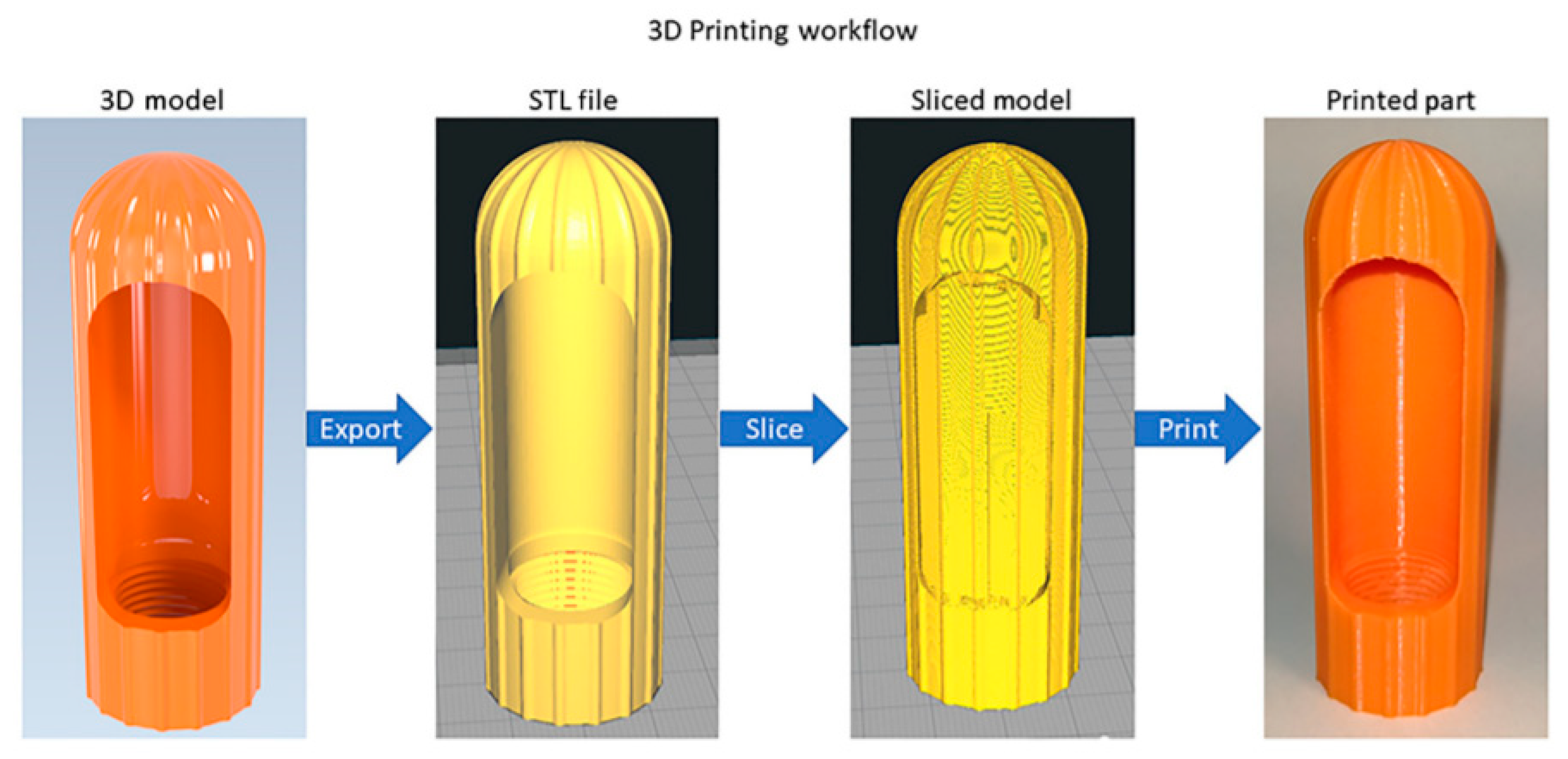
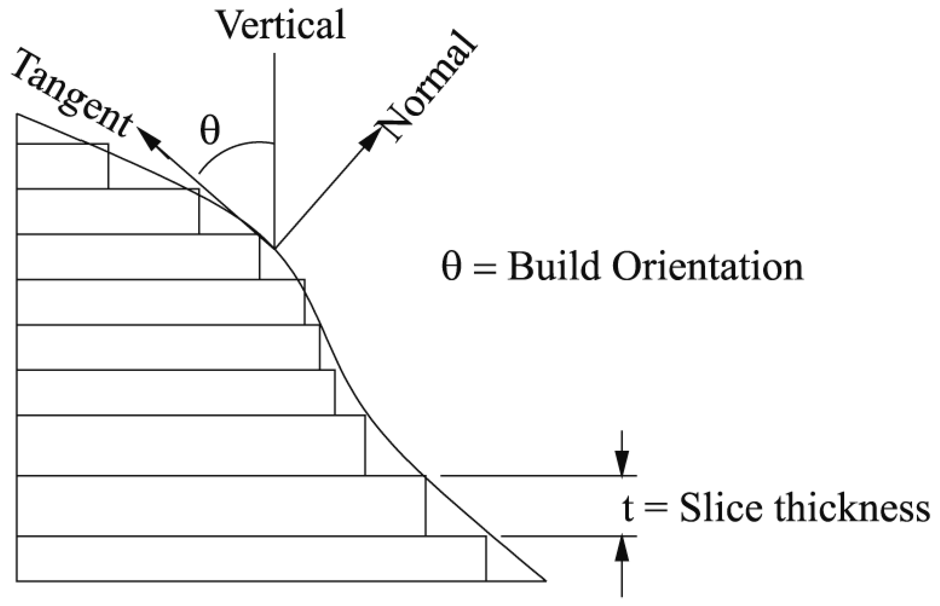
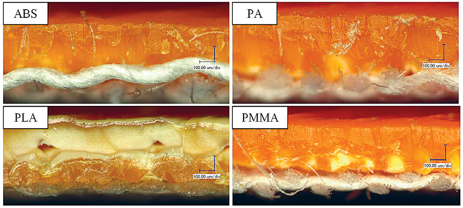
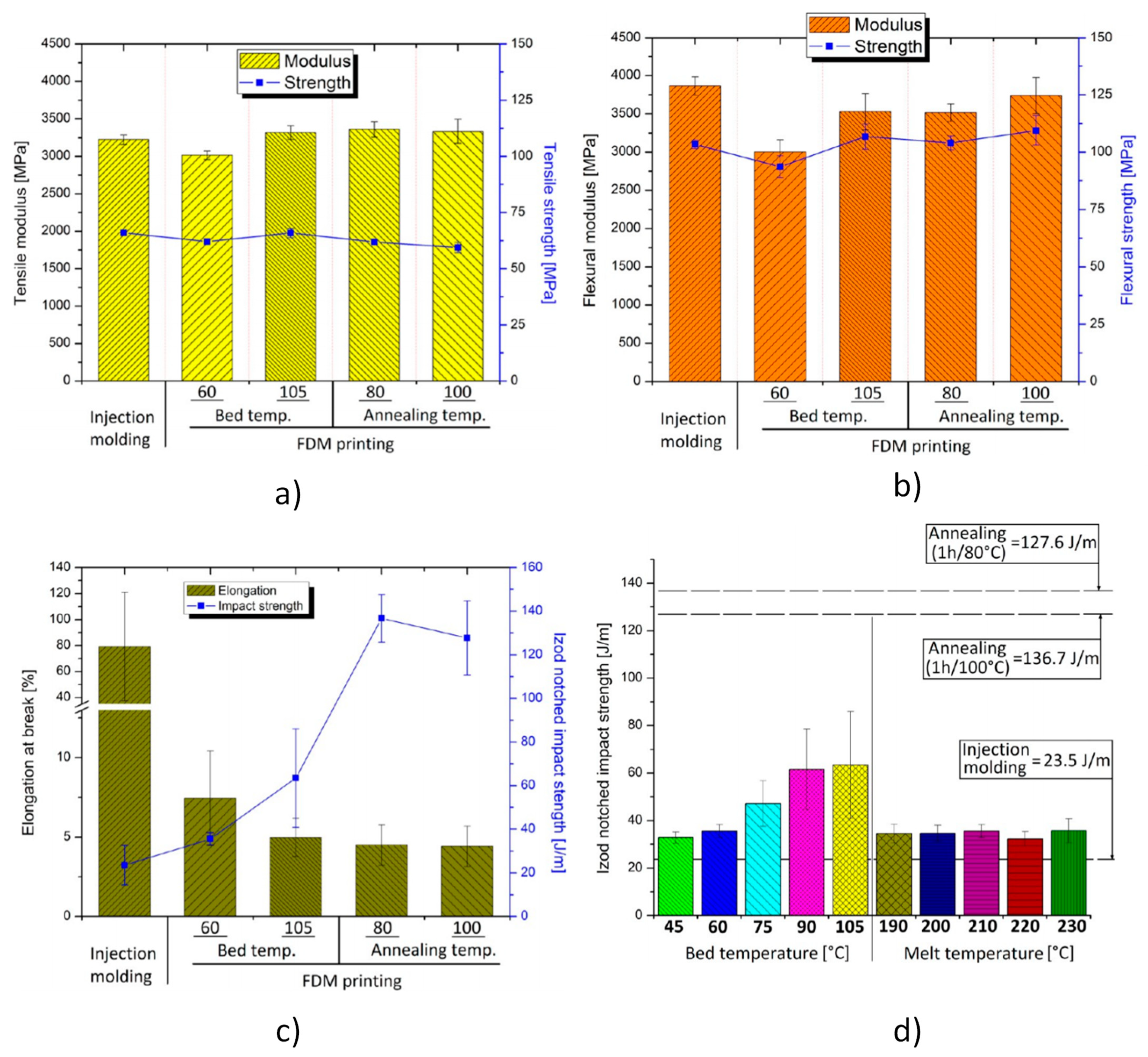
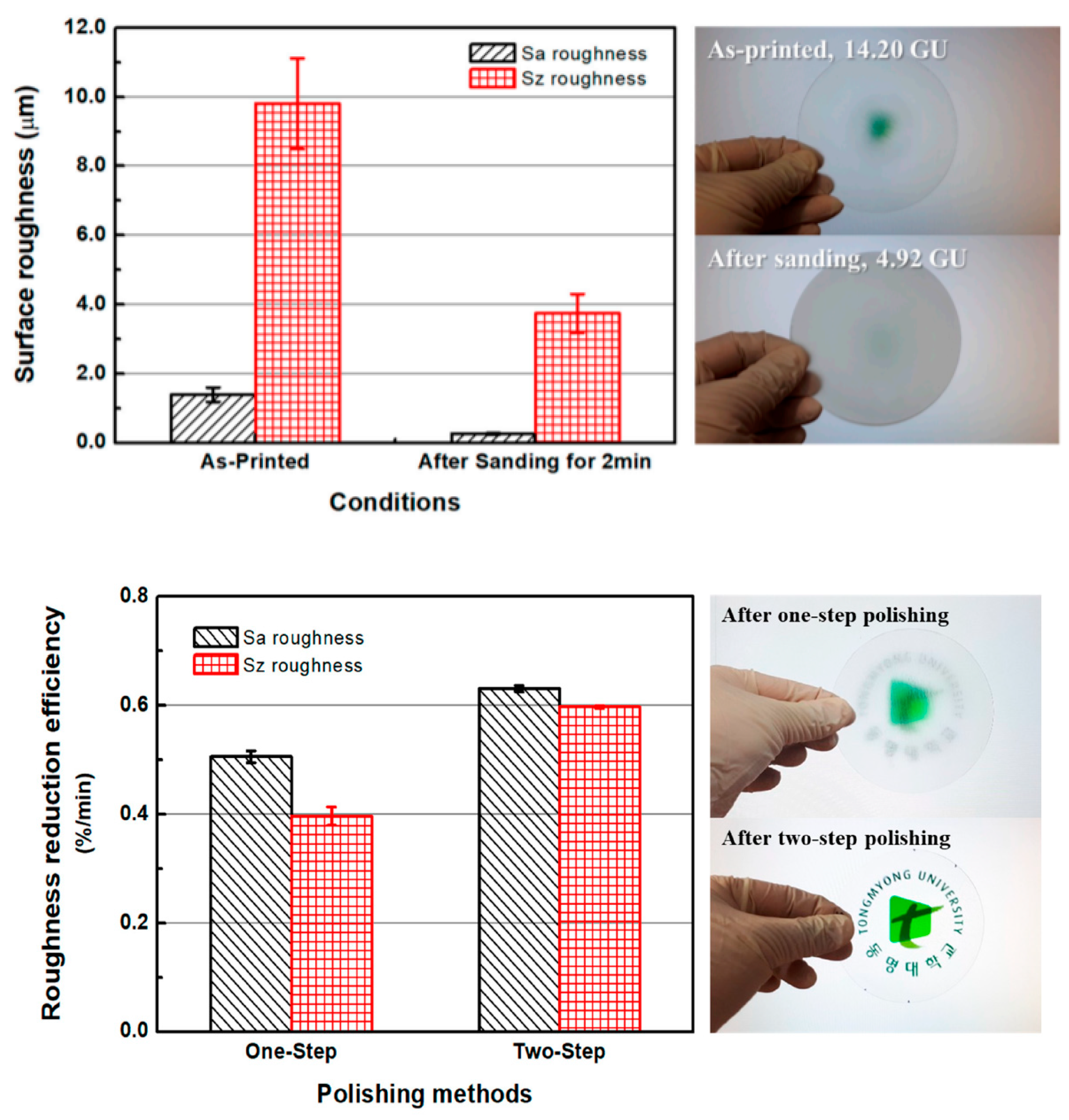
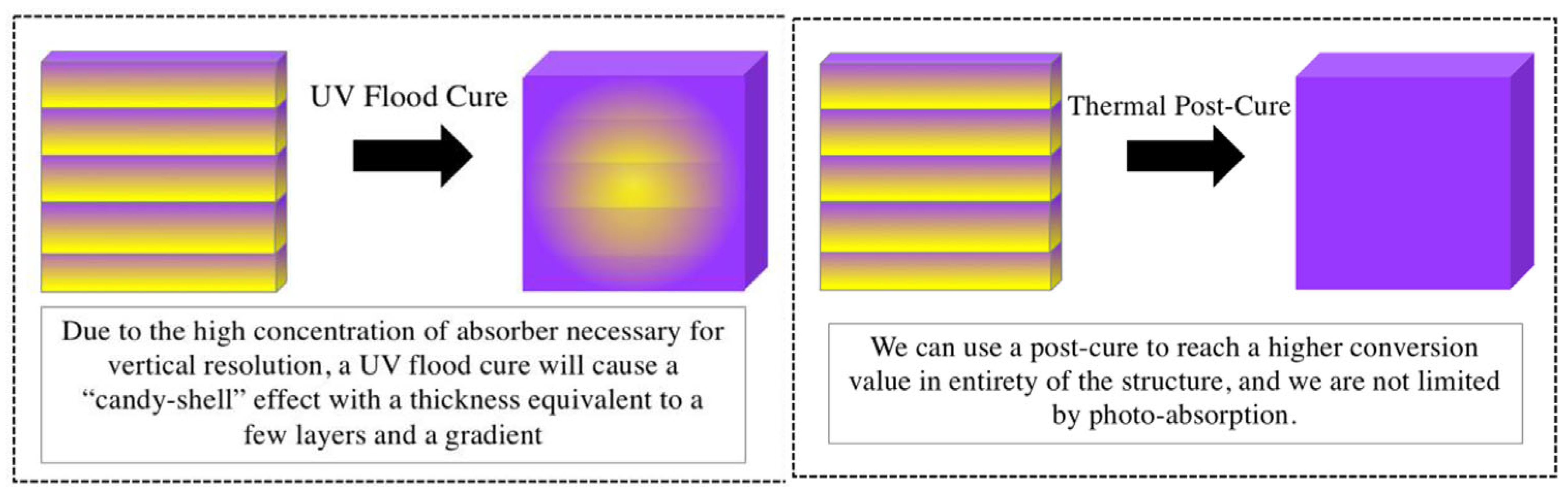
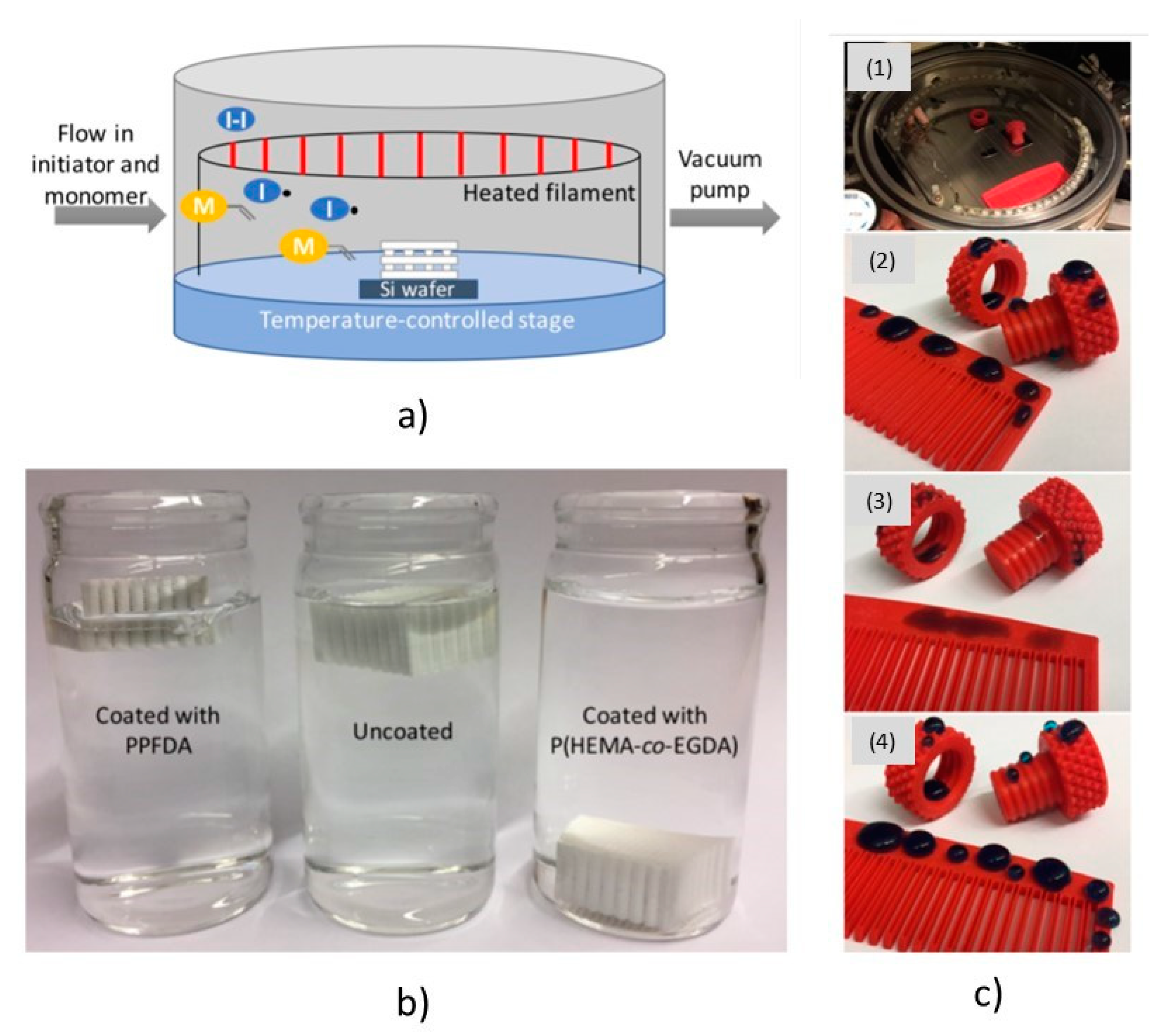
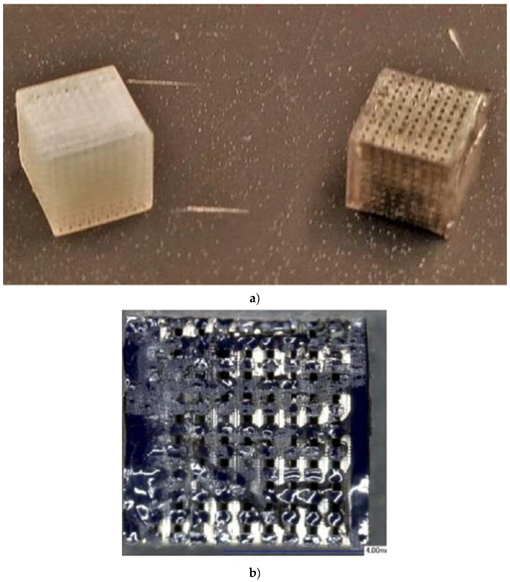
Table 1.
Summary of post-processing methods applied to FDM-printed polymers (material removal).
| Material | Post-Processing Technique | Advantages | Disadvantages |
|---|---|---|---|
| All FDM thermo-plastics | Material Support Removal. Usually done for most 3D printing methods wherein the raft and generated supports are removed [38,109,111,121] | Shape consistency [121] | Unpolished print texture [121] |
| Greater flexibility of design [38,111] | Supports can damage the part during removal [109,111] | ||
| Use of minimal tools [111] | Can sometimes restrict the design freedom of the product [111] | ||
| Quick and easiest method of post-processing [109,111,121] | Incomplete removal of supports affect the accuracy/appearance of the print [121] | ||
| Dissolvable support removal. Soluble supports is dissolved by soaking the part in either water or another solution, leaving little to no marking or residue [111,121] | Applicable and is recommended for complex geometry prints [121] | When done incorrectly, may result to warping and bleaching of the print [121] | |
| Leaves a smooth surface on support marks [121] | Unpolished print texture [121] | ||
| Leakage may create small holes or divots on the print texture [121] | |||
| Sanding. Done by carefully sanding the surface of the model, using sanding paper with varying grit: from low to high for finishing [31,32,38,109,110,111,121,148,149,150,151,152] | Produces extremely smooth surface finish [38,110,121,151,152] | Labor and time intensive [38,109,151,152] | |
| Uses minimal tools [31,38,111] | Can affect health issues when excess fine materials are inhaled [111] | ||
| Minimal costs [111] | May produce an uneven texture [111] | ||
| Creates an effective additional room for post-processing such as painting [110,121,150] | Difficult for complex geometry prints [31,109,121,151,152] | ||
| May affect the accuracy of the part if sanding is aggressively done [121] | |||
| Polishing. Done after sanding by using a small amount of cloth to rub on the surface of the 3D prints in circular motion [111,121,149] | Improves print texture without warping any part [121] | Sometimes require sanding first to achieve the desired finish [121] | |
| Produces an aesthetical surface prints [111,121] | Requires proper safety precautions [111] | ||
| Cost-effective [121] | Paint/primer may not stick to the surface of the part after polishing [121] | ||
| Sandblasting. Done by spraying small particles (sand, glass balls, walnut shells, etc.) to remove layer lines [110] | Quick and easy to apply [110] | Not intended for small/weak objects [110] | |
| PLA and ABS | Hot Air Gun. Used to remove small filaments through the use of an air gun with several types of nozzles heated 50–650 °C [153] | Brings back color after sanding/filing [153] | Knowledge of using the right temperature is needed [153] |
| PLA | CO2 Laser Cutting. Done by cutting and shaping using CO2 laser [113] | May improve geometrical precision and dimensional accuracy [113] |
Table 2.
Summary of post-processing methods applied to all FDM-printed polymers (material addition).
Table 2.
Summary of post-processing methods applied to all FDM-printed polymers (material addition).
| Material | Post-Processing Technique | Advantages | Disadvantages |
|---|---|---|---|
| All FDM Thermo-plastics | Gap Filling. Done by filling the gaps (due to incomplete printing) with auto body filler. Additional sanding may be needed once dry [38,109,121,148] | Epoxies are easily primed and sanded making an additional room for post-processing [121] | Some filling materials may dry opaquely which results in discoloration on the surface of the print [121] |
| No surface discolorations [121] | May require additional sanding for better texture [121] | ||
| Priming and Painting. A thin layer of the primer may be coated to ensure details of the prints are not altered/covered before finally putting a paint according to preferred aesthetics. [31,109,110,111,121,148,149,153,154,155] | Increase aesthetical factors [110,111,121,155] | Paint and primer can be bulky on the surface prints [121] | |
| The visual appearance of the final product has complete flexibility [111,121] | Relatively time-consuming [111,155] | ||
| Can be costly in terms of the number of materials used [111,121] | |||
| Aluminum Filled Epoxy Resin as Filler. This filler can work for small hole or voids which can be easily managed. [121,156] | An outer protective “shell” may be provided around the print [121] | Surface layer lines may still be visible [121] | |
| Excessive use of epoxy may affect the fine details of the print [121] | |||
| Improved surface texture up to 83.85% [156] | |||
| Metal Plating. Done by coating the 3D-printed plastic with a thin layer of conductive paint. After allowing the conductive coating to dry, sanding may be necessary to ensure a smooth surface finish. [121,151] | Increases strength of the plastic part [121,151] | Relatively costly [121] | |
| As the coating is very thin, tolerances may be maintained if the plating is correctly done [121] | Too many safety precautions are needed [121] | ||
| Extremely smooth surface finish [121,151] | |||
| Applying Metallic Powder and Epoxy. Done by mixing clear gloss epoxy with metallic powder [157] | Quick, cost-effective alternative with convincing metallic finish on the surface of the part. [157] | Too much powder added will result to rough texture and leafed gold look [157] | |
| Hydro Dipping. Done by applying printed graphic designs to solid objects using special water transfer paper [158] |
|
| |
|
|
Table 3.
Summary of post-processing methods applied to specific types of FDM-printed polymers (material addition).
Table 3.
Summary of post-processing methods applied to specific types of FDM-printed polymers (material addition).
| Material | Post-Processing Technique | Advantages | Disadvantages |
|---|---|---|---|
| ABS | Electroplating. Done by depositing a thin layer of metal (e.g., gold, silver, nickel, or chromium) to the print surface making it look shinier while providing a wear-resistant and hard surface with reflective properties [31,111] | Significantly enhances the look, feel, and surface properties of a part [111] | Expensive, complex, and requires a lot of skill [111] |
| Increases strength and durability of the part [31,111] | |||
| Many outsourcing options exist for electroplating [111] | |||
| PLA and ABS | Polymer Coating of Textile Fabrics. Done by melting the polymers and coating it to the textile fabric [118] | Significantly increases the adhesion between the textile fabric and polymer [118] | |
| Two-part Epoxy Solution Method. Consists of a resin and a hardener mixed together in an aluminum foil plate until they form a smooth, miscible blend that will then make the part smooth and glossy [157,159] | Very shiny smooth finish, and makes parts strong and durable [157,159] | ||
| PLA | Epoxy Coating. Done by allowing the print part to soak in the epoxy liquid for about 20–25 mins which is enough duration to seep the liquid into holes [150,160,161] | Due to its chemical properties, the resultant coating is usually solvent-resistant, durable, and tough [150] | Potential health risk [150] |
| PLA and PETG | Electroless Plating of Cu and NiP. Done by coating Cu and NiP bath on the surface of the prints using temperatures similar to the glass transition temperatures of the polymers [162,163] | Coatings have good adhesion to the substrate [162] | PETG adhesion should be high enough to prevent partial delamination (especially) on flexible substrates [162] |
| Polycaprolactone (PCL) | Cellulose Nanofibrils Material (CNF) Coating. Cellulose nanofibril material (CNF) is coated on the scaffold. This may improve the surface properties of the print [164] | May enhance cell attachment, proliferation and osteogenic differentiation [164] | High cost of manufacturing [164] |
| May improve the performance of 3D-printed PCL scaffolds (which may be applicable for bone tissue engineering) [164] | Complex procedures required for purification [164] | ||
| PLA, nylon-6, PP, PET, co-polyester, HIPS, and PET, some brands of PEI, ASA, and ABS | Food Safe Coatings and Sealants (food-grade epoxy or polyurethane resin). Done by dip coating the parts with a food grade polyurethane or resin epoxy to prevent bacteria build-up [165] | Reduces the risk of bacteria build-up and particle migration [165] | Coating does not always guarantee food safety for prolonged use [165] |
Table 4.
Summary of Post-Processing Methods applied to FDM-printed Polymers (Other Treatments).
| Material | Post-Processing Technique | Advantages | Disadvantages |
|---|---|---|---|
| ABS | Cold Welding. Manually clamping two printed parts by brushing lightly with acetone to be chemically bonded. [121] | Acetone will not change the surface color of the 3D-printed part [121] | Can be a weaker bond on some parts [121] |
| The joint may copy the properties of ABS after drying (natural look) [121] | Too much acetone may dissolve parts unintentionally [121] | ||
| Microwave Treatment. Melts the ABS thermoplastic matrix near the CNTs—improves inter-layer adhesion. [3,166] | Stronger layer adhesion, tensile and flexural properties [3,166] | ||
| Chemical Post-Processing Treatment. (Acetone, Ester and Chloride Solvent) [3,110,111,156,167] | Improves texture appearance [3,156] | Time difficulties may vary accordingly which can result in deformation and alteration of parts [3,111] | |
| Acetone vapor-polishing. Done by dissolving the liquid/acetone in order to have a concentrated atmosphere of the vapor that will eventually develop the smooth effects on the print. [16,31,109,111,121,152,153] | Better interlayer adhesion of ABS material when used at the right operating temperature. [16,109,153] | May affect the dimensional accuracy of the part [109,111] | |
| Reduces the capacity of ABS 3D-printed material to withstand higher operating temperature [16] | |||
| The relatively cheap cost of acetone makes this post-processing cost-effective. [111] | Too many safety precautions [109,111,153]. May require constant observation and a well-ventilated area [109,111] | ||
| PET-G | Annealing. Done by subjecting parts under varying temperatures and time. [124] | Increases the interlayer tensile strength when given appropriate temperature [124] | |
| Increases the interlayer Young’s Modulus by 1.65 times compared to unannealed composite, as well as 32 times compared to annealed 3D-printed polymer. [124] | |||
| 64% increase in interlayer Strain-to-failure of 3D-printed amorphous part [124] | |||
| PLA | Annealing. Done by subjecting specimens into varying temperatures and time [124] | Doubles the interlayer tensile strength if annealed at an appropriate temperature [124] | |
| Increases the Interlayer Young’s Modulus by 1.48% than unannealed 3D-printed composite [124] | |||
| 49% increase in interlayer Strain-to-failure of semi-crystalline composite [124] | |||
| Gluing (Anabond). Gluing the parts together to form a larger build. [111,148] | Simple and relatively cheap process [111] | Bond is not too strong [111] | |
| PEEK | Annealing. Annealing above the glass transition temperature (200–300° C) [168] | May enhance the interlayer adhesion in some printing conditions [168] | Undesired porosity may form during the 3D printing process [168] |
Table 5.
Summary of Post-Processing Methods Applied for polymers printed via Stereolithography.
| Material | Post-Processing Technique | Advantages | Disadvantages |
|---|---|---|---|
| Durable and General-Purpose Resin | Basic Support Removal. [38,125,154] | Gives complete control over the finish [38,125] | Sometimes not aesthetically pleasing and requires a high skill level to achieve a clean finish [125] |
| Shape consistency [125] | |||
| Sanding of Support Nibs [125] | Smooth finish that hides surface imperfections [125] | Sometimes result in uneven texture (due to non-uniform sanding) [125] | |
| May not be aesthetically appealing (e.g., on clear resin) [125] | |||
| Wet Sanding [38,125] | Excellent smooth finish [38,125] | Lower accuracy on the supported side [125] | |
| Ideal for complex geometries [38,125] | May produce white/light spots on the print [125] | ||
| Mineral Oil Finish [38,125] | May result in a semi-transparent finish for clear resins [125] | Paint may not adhere well to the surface [38,125] | |
| Spray paint (clear UV protective acrylic) [125] | Clear finish on complex geometries for clear resin [125] | Typically results in an ‘orange peel’ effect on the surface | |
| Offers UV protection [125] | Shape accuracy and consistency [125] | ||
| Not suited on moving parts [125] | |||
| UV Post-curing [3] | May improve the mechanical strength of the part due to the complete curing of remaining resin [3] | ||
| Post-curing at a higher temperature may lead to shorter curing time resulting to higher strength of the part. [3] | |||
| Microwave Curing [3] | Small effect on the strength/stiffness of [3] | ||
| Conventional Heating [3] | Results to higher strength compared to UV Post-curing and microwave techniques. [3] | ||
| Vibratory Bowl Abrasion Finishing [156] | Nice surface finish in a short amount of time with improvement of around 74%. [156] | ||
| Ultrasonic Abrasion Finishing [156] | May improve the surface of the parts [156] | ||
| Smart Part Washer [109] | Automates the washing process [109] | ||
| Formwash/Formcure [3,109] | Automates washing/curing processes [3,109] | ||
| Somos Resin | UV Post-curing and Thermal Post-curing (Combination of both) [3] | Optimal thermal, mechanical and electrical properties. [3] | |
| Clear Resin | Polished to clear transparent finish [125] | Clear finish (similar to glass) [125] | Labor-intensive [125] |
| Smooth surface [125] | May not be employed for parts with complex geometries [125] | ||
| Standard Clear Resin | UV Curing [100,109,129,154] | Accounts for 73% of the specimen mechanical behavior [129] | Different temperatures are recommended for different types of resin. [100] |
Table 6.
Summary of Post-Processing Methods Applied for powder-based polymers printed via Three-Dimensional Printing (3DP) and Selective Laser Sintering (SLS).
Table 6.
Summary of Post-Processing Methods Applied for powder-based polymers printed via Three-Dimensional Printing (3DP) and Selective Laser Sintering (SLS).
| Material | Post-Processing Technique | Advantages | Disadvantages |
|---|---|---|---|
| SLS Materials (Nylon and Polyamide) | Standard Finish [38,132,154] | Smooth finish [38] | Limited color options (typically white) [132] |
| Shape accuracy and consistency [38,132] | |||
| Cost effective [132] | |||
| Media tumbled (vibro polish) [132] | Excellent smooth finish [132] | Not suitable for complex geometries [132] | |
| Multiple parts can be done at the same time [132] | Removes sharp edges which may alter part geometry [132] | ||
| Removes sharp edges [132] | |||
| Dyeing [38,132] | Multiple ranges of color options [132] | The penetration of the dye may only be ~0.5 mm deep [132] | |
| Will not affect part dimensions [132] | |||
| Multiple parts may be dyed altogether [132] | |||
| Cheaper compared to other coloring methods [38,132] | Will not result in a glossy finish [132] | ||
| Very much applicable for complex geometries [132] | |||
| Spray paint or lacquering [132,153] | Improves mechanical properties [132] | Labour intensive if many parts will be coated [132] | |
| May result in a glossy smooth clear or colored surface [132] | Impacts overall part dimensions [132] | ||
| Improves UV protection [132] | Requires good surface preparation (all loose powder should be removed) [132] | ||
| Watertightness [132] | Further improves water resistance [132] | Coatings are usually thick and may affect shape accuracy and consistency [132] | |
| Improves mechanical strength [132] | |||
| Metal coating [38,132] | Improves functionality and strength [38,132] | Increases lead time, costly, requires high level of skill [132] | |
| Aesthetically parts will have a metal finish [132] | |||
| Allows for electrical conductivity [38,132] | Available types of metals are limited [132] | ||
| Excellent surface finish may be achieved [132] | |||
| Vibratory Grinding [156] | Parts without complex structure are readily amenable [156] | ||
| Sintering [3] | May improve mechanical properties [3] | Obvious shrinkage often takes place [3] | |
| Infiltration [3] | Shrinkage may be avoided. It is also possible to generate higher density parts. [3] |
Publisher’s Note: MDPI stays neutral with regard to jurisdictional claims in published maps and institutional affiliations. |
© 2021 by the authors. Licensee MDPI, Basel, Switzerland. This article is an open access article distributed under the terms and conditions of the Creative Commons Attribution (CC BY) license (https://creativecommons.org/licenses/by/4.0/).
Share and Cite
MDPI and ACS Style
Dizon, J.R.C.; Gache, C.C.L.; Cascolan, H.M.S.; Cancino, L.T.; Advincula, R.C. Post-Processing of 3D-Printed Polymers. Technologies 2021, 9, 61. https://0-doi-org.brum.beds.ac.uk/10.3390/technologies9030061
AMA Style
Dizon JRC, Gache CCL, Cascolan HMS, Cancino LT, Advincula RC. Post-Processing of 3D-Printed Polymers. Technologies. 2021; 9(3):61. https://0-doi-org.brum.beds.ac.uk/10.3390/technologies9030061
Chicago/Turabian StyleDizon, John Ryan C., Ciara Catherine L. Gache, Honelly Mae S. Cascolan, Lina T. Cancino, and Rigoberto C. Advincula. 2021. "Post-Processing of 3D-Printed Polymers" Technologies 9, no. 3: 61. https://0-doi-org.brum.beds.ac.uk/10.3390/technologies9030061
Note that from the first issue of 2016, this journal uses article numbers instead of page numbers. See further details here.