
Design, Construction and Tests of a Low-Cost Myoelectric Thumb


Faculty of Engineering and Mathematics, Bielefeld University of Applied Sciences, 33619 Bielefeld, Germany
*
Author to whom correspondence should be addressed.
Technologies 2021, 9(3), 63; https://0-doi-org.brum.beds.ac.uk/10.3390/technologies9030063
Submission received: 24 August 2021
/
Revised: 31 August 2021
/
Accepted: 2 September 2021
/
Published: 3 September 2021
(This article belongs to the Section Assistive Technologies)
Abstract
:Myoelectric signals can be used to control prostheses or exoskeletons as well as robots, i.e., devices assisting the user or replacing a missing part of the body. A typical application of myoelectric prostheses is the human hand. Here, the development of a low-cost myoelectric thumb is described, which can either be used as an additional finger or as prosthesis. Combining 3D printing with inexpensive sensors, electrodes, and electronics, the recent project offers the possibility to produce an individualized myoelectric thumb at significantly lower costs than commercial myoelectric prostheses. Alternatively, a second thumb may be supportive for people with special manual tasks. These possibilities are discussed together with disadvantages of a second thumb and drawbacks of the low-cost solution in terms of mechanical properties and wearing comfort. The study shows that a low-cost customized myoelectric thumb can be produced in this way, but further research on controlling the thumb as well as improving motorization are necessarily to make it fully usable for daily tasks.
1. Introduction
Prostheses can be subdivided into body-powered, pneumatically powered, and electrically powered ones [1]. While body-powered devices, using the energy of the muscles of a human, are relatively inexpensive and lightweight, they often have other shapes than the original part of the body which they replace, and they can be complicated to use [2]. Electrically powered prostheses, on the other hand, are usually much more expensive and heavier, but for many users easier to handle. Such prostheses can get their signals by different body signals, amongst them by electromyographic (EMG) signals from the residual muscles [3,4]. In this way, there is a better possibility to mimic the natural human movement than with body-powered prostheses. While the best control is reached by an implanted sensor, collecting intramuscular myoelectric signals, usually surface electrodes are applied on the residual limb as a non-invasive technique is often preferred [5,6]. The efficiency of surface electrodes can be improved by transferring nerves to the positions where the surface electrodes are to be placed [7,8]. Previous studies found, e.g., that using myoelectric prostheses can help avoiding cortical reorganization related with phantom limp pain [9].
Myoelectric control is especially often used for upper-limb prostheses [10,11,12,13]. Another important part of the body is the hand, which is also often replaced by myoelectric prostheses [14,15,16]. While research on moving the fingers of a hand prosthesis independently is ongoing [17,18], single finger prostheses are usually not controlled by myoelectric signals. One of the reasons for this finding may be the high costs for myoelectric prostheses in the range of 4000–75,000 $ for upper-limb prostheses [19].
Especially in developing countries, low-cost myoelectric prostheses would be of large help for people who lost a limb. This is why some research groups concentrate on developing cost-effective myoelectric prosthetic devices, especially hands. Atique and Rabbani, e.g., developed a myoelectric prosthetic hand with only the thumb being controllable by myoelectric signals, taken by surface electrodes, in this way enabling holding small objects [20]. Three-dimensional printed prostheses are partly commercially available at lower cost, e.g., approx. 1500$ for the Mark V (Seoul, Korea) [21]. Nevertheless, these prices are still high for people in many countries around the world. A highly interesting initiative, supporting people or also animals who need new limbs, is the e-NABLE online global community, delivering wrist-powered hands and elbow-driven arms in different designs, but not custom-made, by open-source 3D printing designs [22].
Besides these and other low-cost prostheses, there are also attempts to train people with neurological injuries or to extend the physical properties of non-handicapped people by exoskeletons [23,24,25]. Regarding hands or fingers, there are a few studies and design approaches investigating the effect of a third thumb, e.g., controlled by the feet [26], allowing to give people extended motor skills and at the same time enabling neuro-scientific research on neuroplasticity [27,28].
Going one step further, myoelectric prostheses have recently been investigated to be controlled commonly by user intention and robotic automation to improve the prosthesis motions [29]. The interaction between a human and a prosthetic hand is still the most complicated task to be solved, especially due to the problematic or non-existing sensory feedback of the prosthesis [30]. This is why some groups concentrate on evaluating the effect of different kinds of control strategies, such as raw control with raw feedback or filtered control with filtered feedback [31]. Other groups investigated tolerant pattern recognition for the myoelectric prosthesis control to avoid reaction to signal deviations due to untrained conditions [32] or the effect of different learning durations on grasp patterns [33]. On the other hand, different ways of learning, e.g., with augmented reality of game-based training, are recently investigated [34,35].
Here, we present a project combining some of the aforementioned aims. We developed a myoelectric third thumb—in case of able-bodied people—and tested at which positions of the hand it could be ideally added. This thumb could also be used as prosthesis for people who lost their thumb. Low-cost solutions for scanning are discussed, leading to the possibility to prepare custom-made prostheses, which can be 3D printed and controlled with inexpensive electronics by myoelectric signals taken by surface electrodes. The study shows that developing a low-cost customized myoelectric thumb is possible, but more research is needed regarding the exact positioning of the thumb as well as partly improving the motor and the material of the fishing line, actuating the thumb.
2. Materials and Methods
In the conception phase, a requirement specification for an extra thumb was developed, containing the following points:
- -
- Enabling holding round objects with diameter 60 mm;
- -
- Custom-made hand part with good fit to desired position;
- -
- Rotation of minimum 40° of the thumb;
- -
- Maximum dimensions of length 80 mm and width 20 mm to make the extra thumb similar to a normal one;
- -
- No sharp edges, ergonomic construction;
- -
- Using a spring to let the thumb relax into the neutral position;
- -
- Maximum mass, including servomotor, of 50 g;
- -
- Production by 3D printing;
- -
- Low-cost materials and parts, ideally leading to an overall price below 100 €.
The approaches to reach these goals are described below.
2.1. Customization
Different ways of producing a 3D model of the own hand were tested: Scanning by a smartphone using the app Scann3D (from SmartMobileVision, Budapest, Hungary); or using the free computer software 3DF Zephyr Free (3Dflow SRL, Verona, Italy), which enables producing a 3D object from 2D photographs that were taken with a Nikon Coolpix P510.
The gained 3D object was imported in Autodesk Meshmixer (Autodesk, Inc., San Rafael, CA, USA) where errors in the 3D shape were corrected. Afterwards, the 3D model was imported in MeshLab (Visual Computing Lab, Institute of Information Science and Technologies “Alessandro Faedo”—ISTI, National Research Council of Italy, Pisa, Italy), where meshing errors were corrected.
Next, the mesh was imported into Fusion 360 (Autodesk, Inc.), to scale the model to the correct dimensions. Finally, holders fitting to two different positions of the meshed hand were constructed, one between thumb and wrist joint and another one between small finger and wrist joint. Besides, a holder for the electronics and electromechanical parts at the arm near the wrist was developed.
The whole development process is shown in the chart in Figure 1.
2.2. 3D Printing
The printed parts were exported from Fusion 360 as stl files and sliced with the software Cura (Ultimaker B. V., Utrecht, The Netherlands). Printing was performed using an Ender V2 (Shenzhen Creality 3D Technology Co., Ltd., Shenzhen, China) with a nozzle diameter of 0.4 mm. As filament, polylactic acid (PLA) was chosen, which has advantages like good printability, being eco-friendly and degradable, and its shape memory properties allow for bending parts that cannot be printed easily in the desired shape [36,37]. The following parameters were used for printing: layer thickness 0.16 mm, 3 perimeters, fill density 20%, printing temperature 210 °C, printing bed temperature 50 °C, printing speed 50 mm/s, and the angle from which an overhang needs support structure was chosen as 51°. These support structures were carefully separated from the printed objects after printing, partly supported by a knife.
2.3. Springs to Let the Thumb Relax
To enable relaxation of the thumb without muscle contraction, a torsion spring as well as a tension spring were investigated. In both cases, different possibilities to mount the springs at the 3D printed parts were investigated.
2.4. Electronics, Sensors and Programming
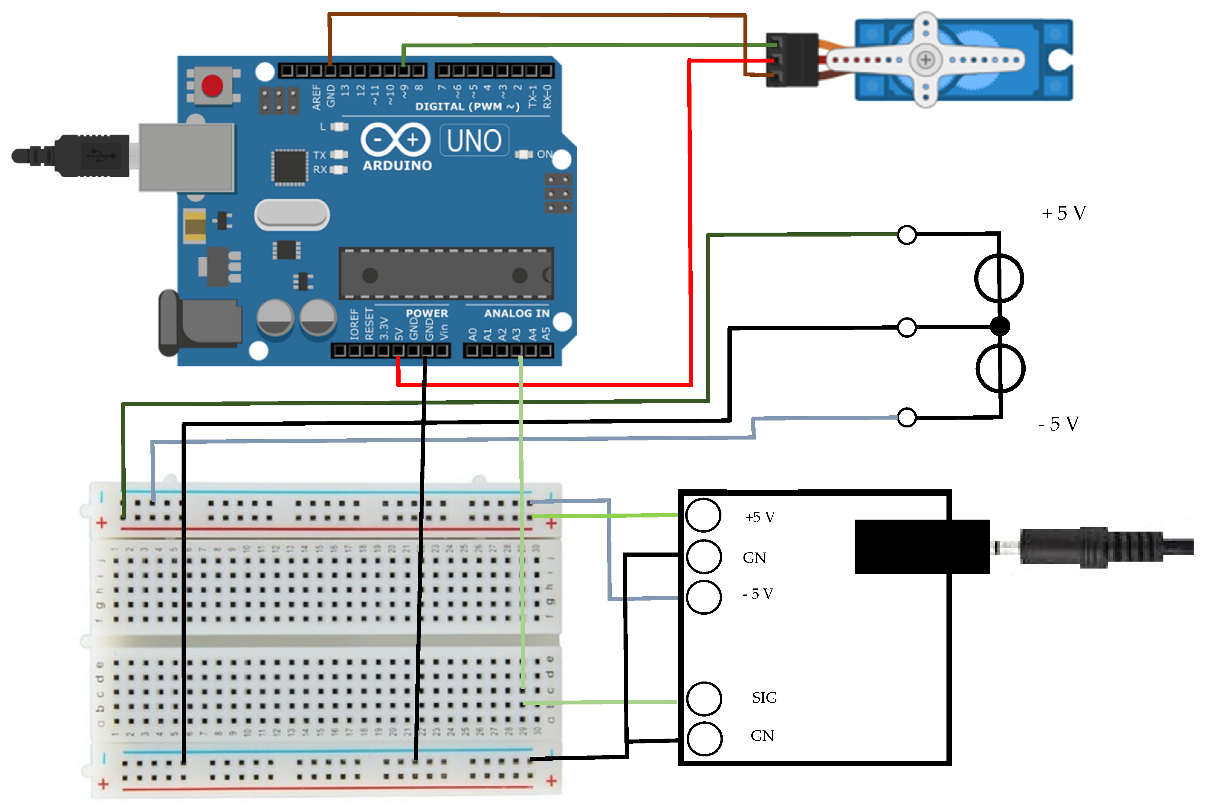
The third thumb was controlled by an Arduino Uno, testing two different programs (cf. Appendix A). Figure 2 shows the wiring.
The servomotor used in this work is an SG90 (Tower Pro, Taipei, Taiwan) with the following parameters [38]: dimensions 23 mm × 12.2 mm × 29 mm, mass 9 g, rotation speed 0.1 s for 60°, torque 1.8 kg/cm, voltage 4.8 V. This servomotor pulls a string (here a fishing line) to actuate the phalanges.
The myoelectric signals were taken by three surface electrodes including a reference electrode (standard ECG gel electrodes) on the forearm and evaluated by the muscle sensor board V3 (Advancer Technologies, Raleigh, NC, USA). The electrodes were placed on the Flexor carpi ulnaris and the Flexor carpi radialis, i.e., the muscles responsible for deflection and extension of the wrist joint. It should be mentioned that rotation of the third thumb was included into the design for 3D printing, but not yet controlled by myoelectric signals.
3. Results
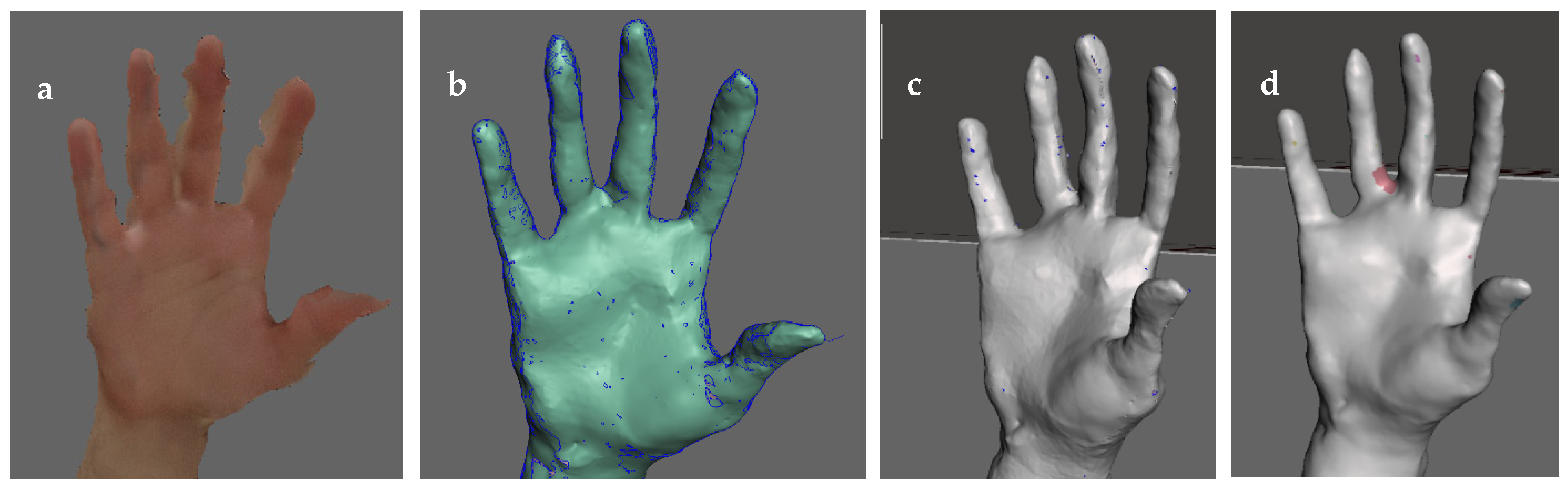
While scanning a hand did not lead to satisfactory results, using 3DF Zephyr principally enabled preparing a 3D model of a hand with several optimization steps, as visible in Figure 3.
Here, different errors occur. Figure 3a shows a version in which the hand was not held at the identical position during taking 50 photographs, resulting in a “shadow hand”. Insufficient contrast between hand and background may lead to insufficient edge detection and, thus, incomplete parts of the hand, here especially to “holes” in the fingers (Figure 3b). In Figure 3c, an effect is visible that may occur when photographs are taken in front of a monochromatic background. Finally, Figure 3d shows the best result gained by this technique, combining 50 photographs for a chosen reconstruction “human body” and the selection “surface scan”, applying the highest possible resolution. Generally, scanning body parts is much more complicated than scanning rigid objects since the latter keep their position, while the hand here could not be stabilized by any rigid object since all sides had to be photographed without other objects blocking the line of sight.
Next, the model shown in Figure 3d was introduced in Meshmixer (Figure 4a) where, e.g., ring finger and middle finger were separated, as shown in Figure 4b. Next, open areas and meshing errors were corrected (Figure 4c), before the final 3D hand model was derived (Figure 4d).
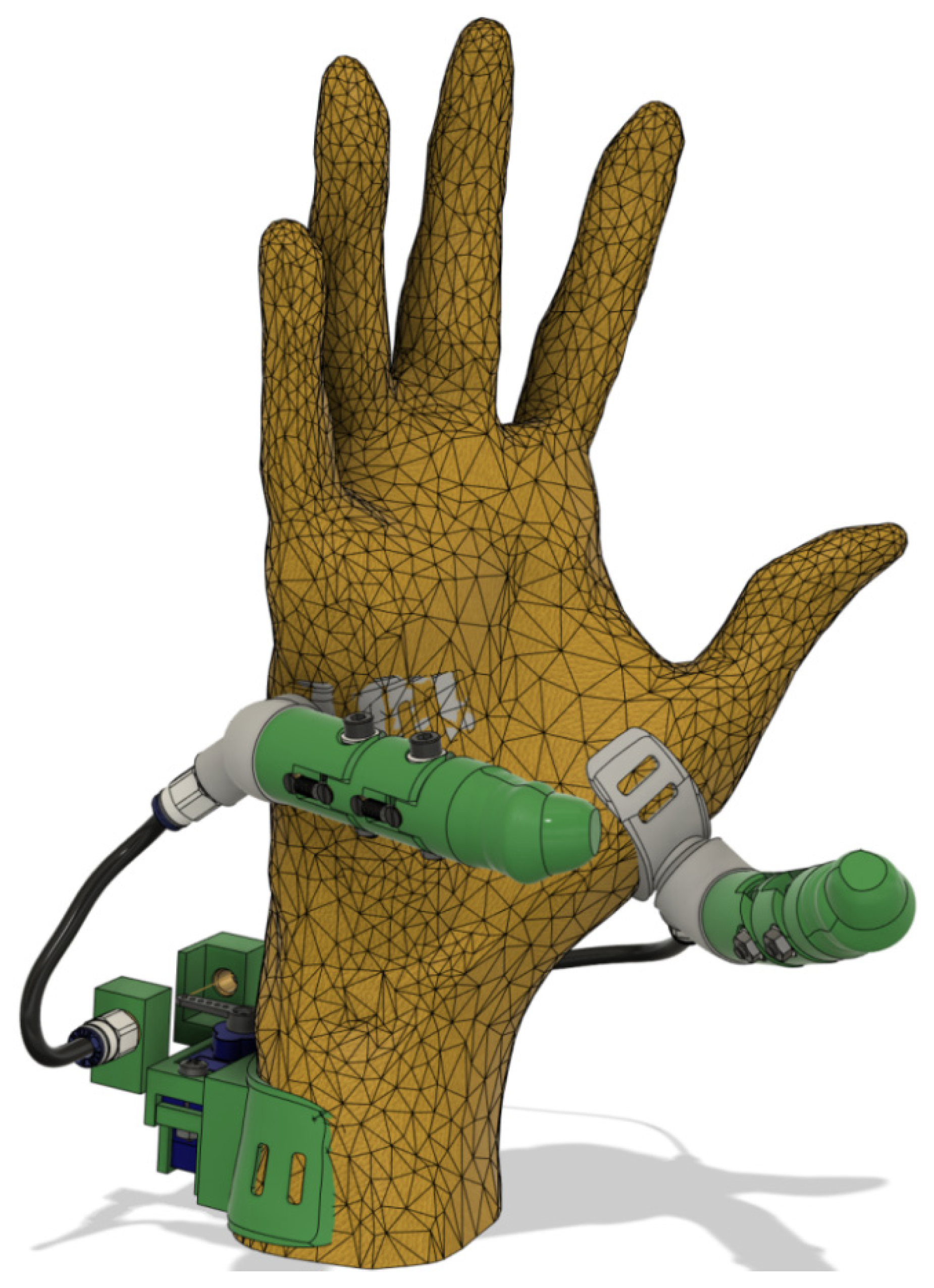
Next, the different holders (one for the motor, two for the different possible positions of the third thumb) as well as the third thumb itself were constructed. The basic constructions are depicted in Figure 5. Here, the holders were fitted to the previously reconstructed 3D hand by constructing a plane, changing it roughly to the desired shape of the holder and drawing it to the surface of the 3D hand. In some areas, the holders were constructed smaller than the hand to allow a tighter fit on the soft hand regions. Next, all edges were rounded.
On the holders, supporting systems (grey parts in Figure 5) were constructed on which the actual thumbs were placed. The whole thumb construction is depicted in Figure 6. Connections between adjacent phalanges are made by screws. All holders contain slits to fix textile bands, ensuring a reliable fixation of the holders on the hand or forearm, respectively.
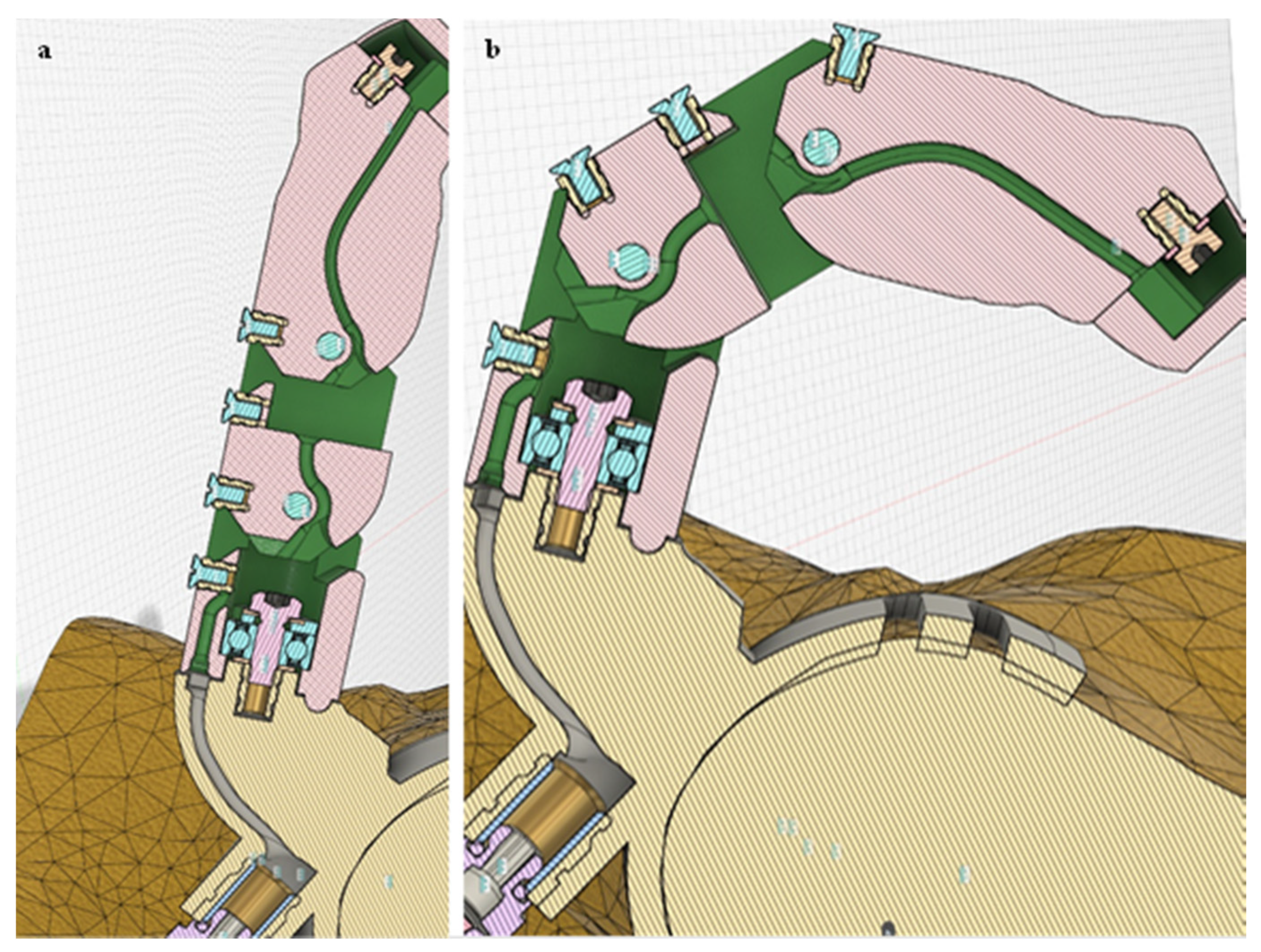
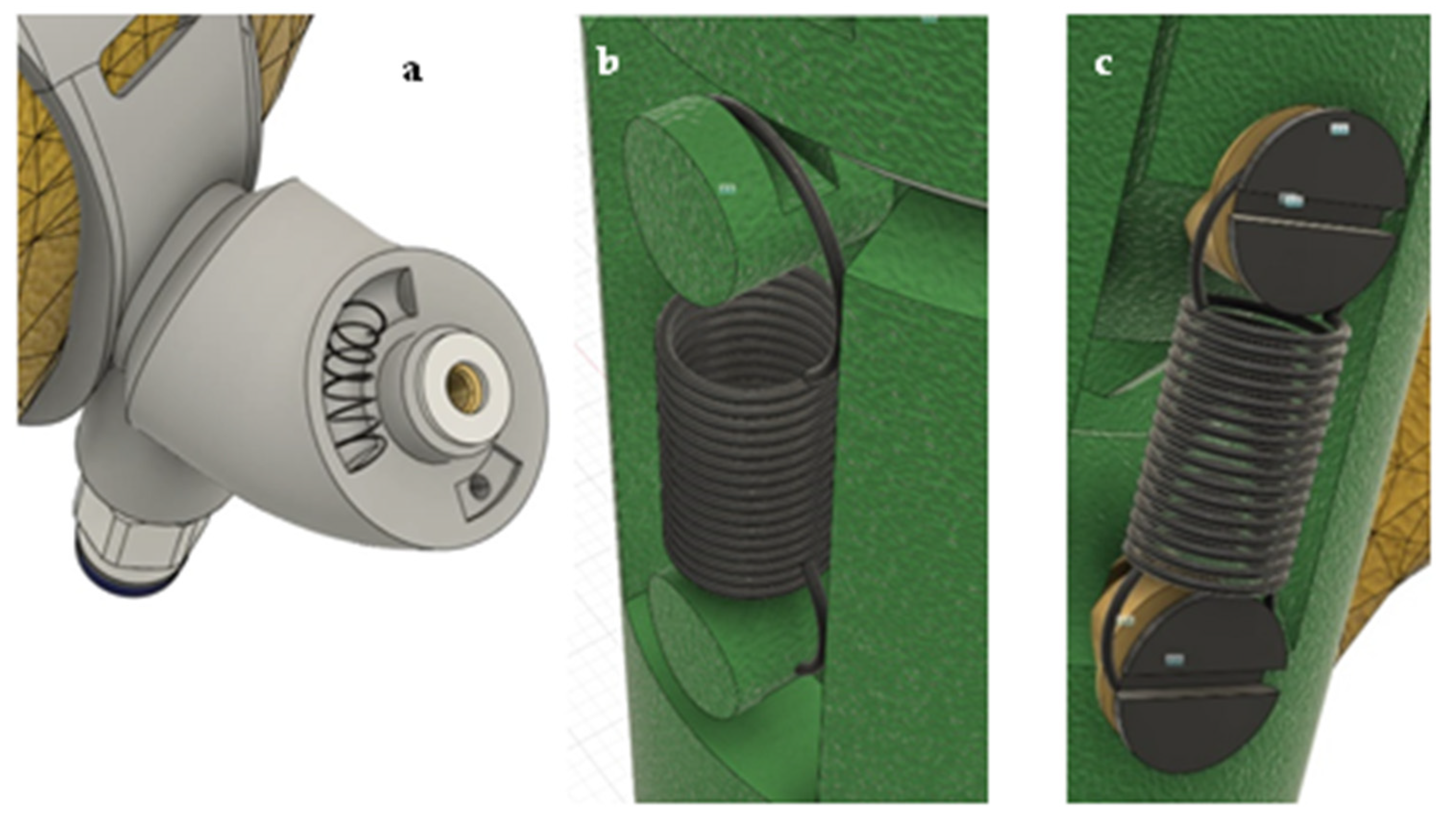
To enable rotation of the thumb, a deep groove ball bearing (623-2Z, 3 mm ID × 10 mm OD × 4 mm wide, light blue part in Figure 6) was pressed into the borehole of the base phalanx. The latter was connected with the supporting system (beige part in Figure 5) by an M3 screw. Annular grooves for a pressure spring (Figure 7a) were added to the supporting system as well as to the base phalanx, letting the thumb rotate back into the neutral position when rotated. The length of the base phalanx is 27.3 mm. The intermediate phalanx can be bent by 50° with respect to the base phalanx and has a height of 28.8 mm. The end phalanx can be bent by 45° with respect to the intermediate phalanx. On its tip, it has an M2 borehole on which a cover is plugged.
Moving the finger is enabled by a fishing line fixed at the end phalanx by this M2 screw and with its other end at the servomotor. The path of the fishing line is depicted in Figure 5 by the green curved grooves in the thumb part and the grey groove in the support system part, respectively. At either ends of the phalanges, the channel guiding the fishing line was extended to avoid clamping it.
To let the thumb move back into a neutral position without detected muscle signals, springs were added between the phalanges. Firstly, a torsion spring was tested; however, placement of the spring was complicated, and no fitting torsion springs were found. Thus, a tension spring was used instead, as depicted in Figure 7. While first tests were carried out by attaching the springs to 3D printed extensions (Figure 7b), this procedure was found not reliable enough, with some extensions breaking during separation of the support material or being abraded during attaching the springs. Thus, in the final version small screws were placed in thread inserts at the ends of the phalanges (Figure 7c).
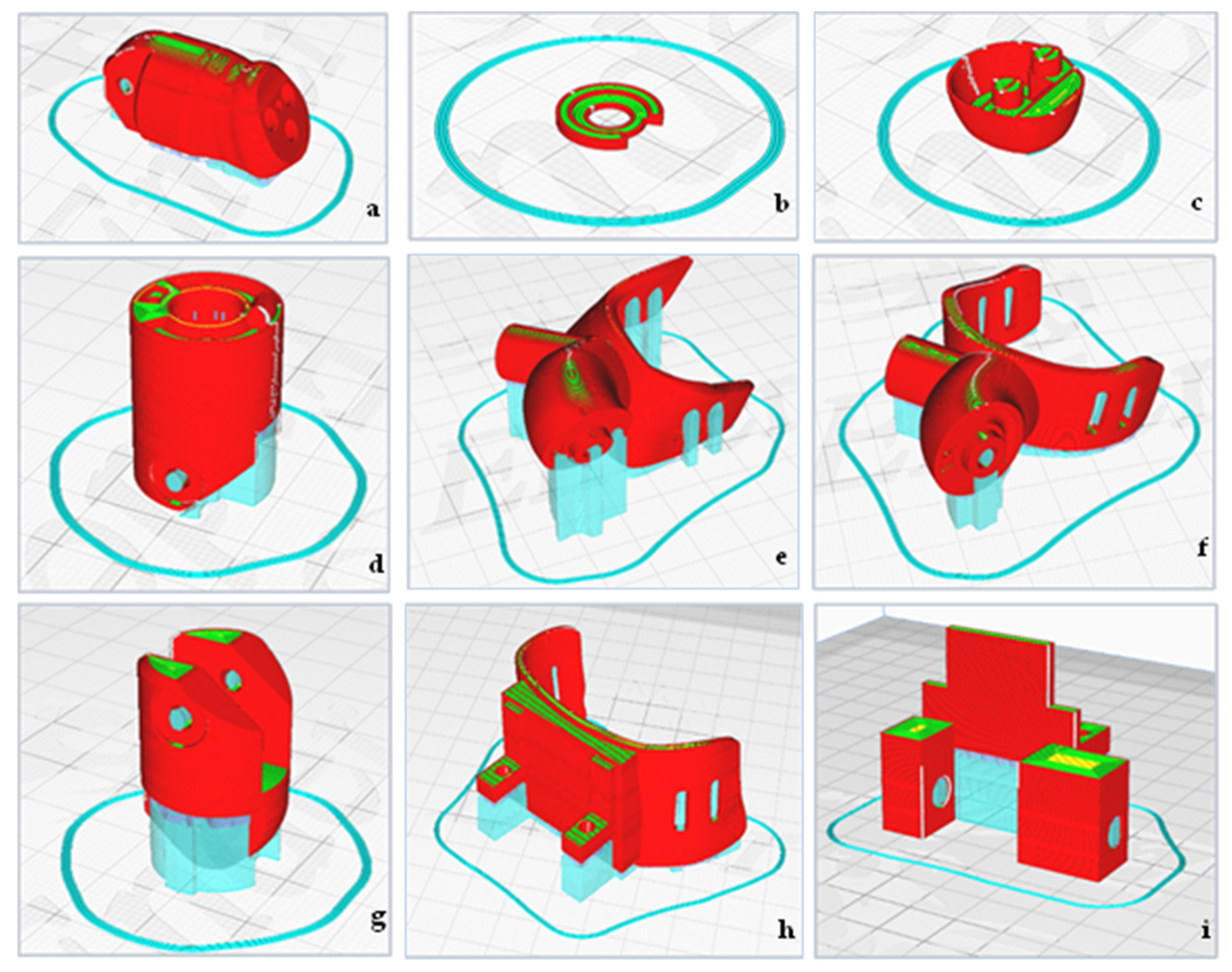
After these iteration steps, the final 3D parts (available at https://www.thingiverse.com/thing:4938144, accessed on 24 August 2021) were printed in the orientations shown in Figure 8. Light blue parts show support structures. Positions were chosen in such a way that boreholes and especially the channel guiding the fishing line were printable without support. Printing of all parts for two additional thumbs took 21 h. After chamfering the parts, the thread inserts were heated by a soldering gun and pressed into the respective boreholes. The fishing line was guided through the channel and fixed with the M2 screw at the end phalanx. From the M5 thread insert at the base phalanx, the fishing line was led into the connector (cf. lower left of Figure 6b) and through the tube (marked black in Figure 5) to the connector at the servo holder. The different parts of the thumb were finally connected with screws, and the springs (Figure 7) were added. Detailed descriptions of the assembly process can be found in the animations for the third thumb in both possible positions in the Supplementary Material.
4. Discussion
During the iterative development of this third thumb or myoelectric finger prosthesis, several potential problems were recognized. A first test was performed with hand holders of thickness 2 mm, which was found to be mechanically insufficient; the slits holding the textile strips broke several times. Thus, the design had to be changed to a holder thickness of 3 mm.
Unexpectedly, the fishing line could be elongated too much, which made it less suitable for rigidly holding objects. Besides, the channel guiding the fishing line was found to be too broad; this additional degree of freedom increased the problem of differing thumb positions with and without load.
On the other hand, the hook-and-loop fastener used here as textile band to fix the third thumb and servo holders was too rigid and should be exchanged by a slightly elastic textile material in a next step.
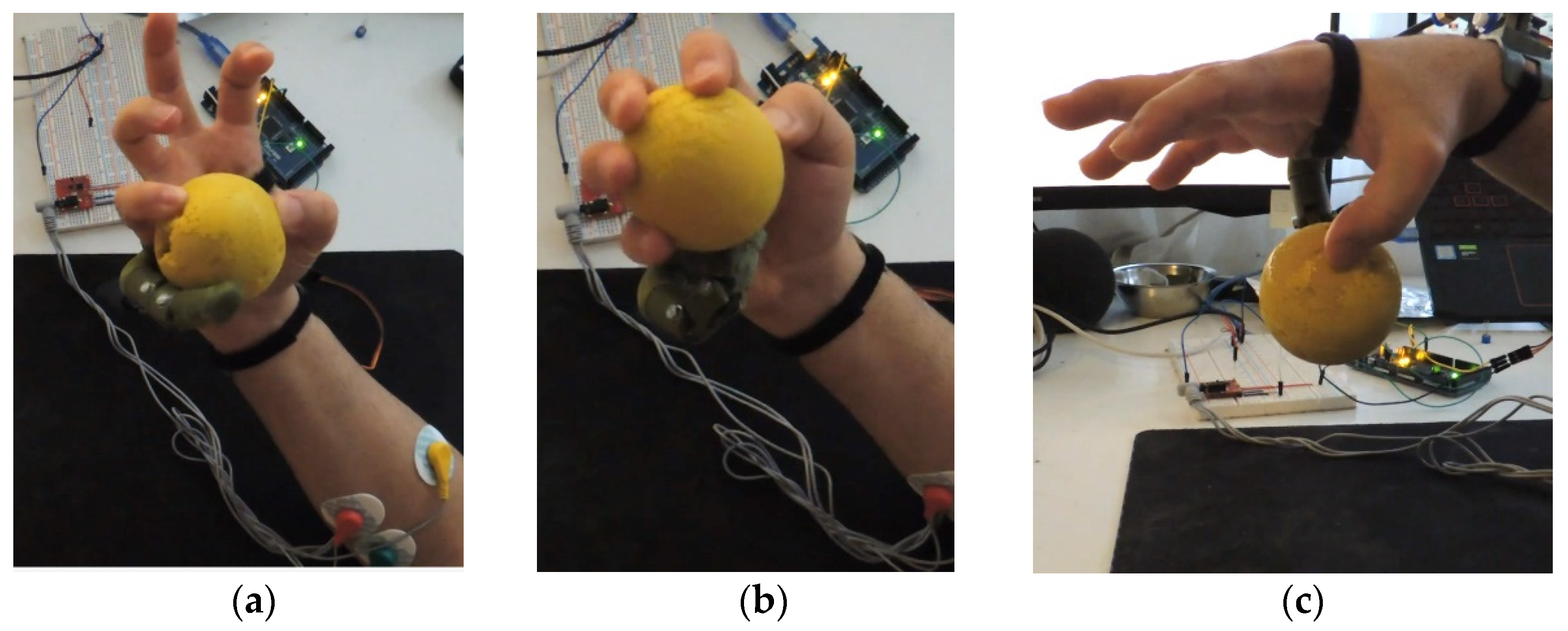
Practical tests of the developed third thumb (cf. third-thumb-tests.avi in the Supplementary Material and Figure 9) showed that a third thumb at the inner side (between original thumb and wrist) could be helpful to grab larger objects since the third thumb could be used like the original one, just with a larger distance to the other fingers. On the opposite side, i.e., between small finger and wrist, it could be used to hold a soft ball, but was sometimes even disturbing, especially during grabbing long objects, such as a bottle of water. Regarding the holders, the third thumb was better wearable between small finger and wrist since there the hand deformed less when an object was taken.
The programs tested during this study (cf. Appendix A) were found to react differently to noise in the EMG signals. The latter had a higher degree of freedom, making movements more reliable, but nevertheless has to be developed further to reduce undesired movements due to noise.
It should be mentioned that this project mainly aimed at producing a customized low-cost myoelectric prosthesis, without applying brain related measured or investigating the effect of training, as the aforementioned studies on using a third thumb did [27,28]. Another difference to Ref. [27] is that here not the big toe, but an arm muscle was used to control the third thumb, making a comparison of training effects complicated. The extra robotic thumb described in Ref. [28] has a different design, but similar degrees of freedom, and is equipped with a force sensor; such a feedback system was not yet implemented here. Other studies mentioning myoelectric finger control are usually related to full hand prostheses [39,40] or evaluate myoelectric signals during finger control in general for future implementation [41,42,43,44].
5. Conclusions
In this project, a low-cost myoelectric thumb was developed. While tested here as third thumb, it can also be used as prosthesis by people who lost a thumb.
This first approach works for grabbing and holding small, lightweight objects. With the improvements pointed out, more functional prostheses or third thumbs can be developed, based on the freely available printing models for 3D printing and programs available as Supplementary Material. Further research is necessary to improve thumb positioning as well as the motor strength and the material of the fishing line, actuating the thumb. Besides, implementation of a feedback can allow for better control of the prosthesis, especially concerning the grabbing force, which is planned to be measured in the next step of the project.
Supplementary Materials
The following videos are available online at https://0-www-mdpi-com.brum.beds.ac.uk/article/10.3390/technologies9030063/s1: animation-thumb-side.avi, showing the assembly and function of the third thumb placed between thumb and wrist; animation-small-finger.avi, showing the assembly and function of the third thumb placed between small finger and wrist; and third-thumb-tests.avi, showing real tests with a third thumb, grabbing and holding a small ball with different combinations of fingers.
Author Contributions
Conceptualization, all authors; methodology, M.A.; investigation, M.A.; writing—original draft preparation, A.E.; writing—review and editing, M.A. and I.W.; visualization, M.A., A.E. and I.W.; supervision, I.W. All authors have read and agreed to the published version of the manuscript.
Funding
This research was partly funded by the HiF funds of Bielefeld University of Applied Sciences.
Data Availability Statement
All data created in this study are presented in this paper or in the Supplementary Material.
Conflicts of Interest
The authors declare no conflict of interest. The funders had no role in the design of the study; in the collection, analyses, or interpretation of data; in the writing of the manuscript, or in the decision to publish the results.
Appendix A
Program code V1:
#include <Servo.h> // includes servo library
Servo SERVO1; // setup servo object
float VALUE; // define float VALUE
int BORDER = 80; // border defined by integer 80
void setup () {
Serial.begin(9600); // sets baud rate to 9600 bits/s
SERVO1.attach(9); // addresses servo library to pin 9
}
void loop () {
VALUE = analogRead(A3); // addresses analog input A3 as VALUE
if (VALUE > BORDER) {
SERVO1.write(0); // SERVO1 receives value 0
}
else {
SERVO1.write(120); // SERVO1 receives value 120
}
Serial.println(VALUE); // serial port receives data VALUE
}
Program code V2:
#include <Servo.h>
#define SLOPE 30
Servo SERVO1;
float DIFF; //define different float values
float NEU_VALUE;
float VALUE;
long timer = 0; // recent time
int DELAY = 100; // delay time
void setup () {
Serial.begin(9600); // sets baud rate to 9600 bits/s
SERVO1.attach(9); // addresses servo library to pin 9
}
void loop () {
if (millis () > (timer + DELAY)) {
VALUE = analogRead(A3);
DIFF= VALUE-NEU_VALUE;
NEU_VALUE = VALUE;
if (DIFF > SLOPE) {
SERVO1.write(0); // SERVO1 receives value 0
}
else if (DIFF < (-SLOPE)) {
SERVO1.write(120); // SERVO1 receives value 120
}
timer = millis ();
}
Serial.println(analogRead(A3)); // serial port receives data VALUE
}
References
- Childress, D.S. Historical aspects of powered limb prosthesis. Clin. Prosthet. Orthot. 1985, 9, 2–13. [Google Scholar]
- Geethanjali, P. Myoelectric control of prosthetic hands: State-of-the-art review. Med. Devices Évid. Res. 2016, 9, 247–255. [Google Scholar] [CrossRef] [PubMed] [Green Version]
- Hahne, J.M.; Biessmann, F.; Jiang, N.; Rehbaum, H.; Farina, D.; Meinecke, F.C.; Muller, K.R.; Parra, L.C. Linear and nonlinear regression techniques for simultaneous and proportional myoelectric control. IEEE Trans. Neural. Syst. Rehabil. Eng. 2014, 22, 269–279. [Google Scholar] [CrossRef] [PubMed]
- Cipriani, C.; Zaccone, F.; Micera, S.; Carrozza, M.C. On the shared control of an EMG-controlled prosthetic hand: Analysis of user-prosthesis interaction. IEEE Trans. Robot. 2008, 24, 170–184. [Google Scholar] [CrossRef]
- Weir, R.F.; Troyk, P.R.; DeMichele, G.A.; Kerns, D.A.; Schorsch, J.F.; Maas, H. Implantable myoelectric sensors (IMESs) for intramuscular electromyogram recording. IEEE Trans. Biomed. Eng. 2009, 56, 159–171. [Google Scholar] [CrossRef] [PubMed] [Green Version]
- Kuiken, T.A.; Li, G.; Lock, B.A.; Lipschutz, R.D.; Stubblefield, K.A.; Englehart, K. Targeted muscle reinnervation for real-time myoelectric control of multifunction artificial arms. JAMA 2009, 301, 619–628. [Google Scholar] [CrossRef] [Green Version]
- Miller, L.A.; Stubblefield, K.A.; Lipschutz, R.D.; Lock, B.A.; Kuiken, T.A. Improved myoelectric prosthesis control using targeted reinnervation surgery: A case series. IEEE Trans. Neural Syst. Rehab. Eng. 2008, 16, 46–50. [Google Scholar] [CrossRef] [PubMed] [Green Version]
- Hijjawi, J.B.; Kuiken, T.A.; Lipschutz, R.D.; Miller, L.A.; Stubblefield, K.A.; Dumanian, G.A. Improved myoelectric prosthesis control accomplished using multiple nerve transfers. Plast. Reconstr. Surg. 2006, 118, 1573–1578. [Google Scholar] [CrossRef]
- Lotze, M.; Grodd, W.; Birbaumer, N.; Erb, M.; Huse, E.; Flor, H. Does use of a myoelectric prosthesis prevent cortical reorganization and phantom limb pain? Nat. Neurosci. 1999, 2, 501–502. [Google Scholar] [CrossRef]
- Fougner, A.; Stavdahl, O.; Kyberd, P.J.; Losier, Y.G.; Parker, P.A. Control of upper limb prostheses: Terminology and proportional myoelectric control—A review. IEEE Trans. Neural Syst. Rehab. Eng. 2012, 20, 663–677. [Google Scholar] [CrossRef] [Green Version]
- Madusanka, D.G.K.; Wijayasingha, L.N.S.; Gopura, R.A.R.C.; Amarasinghe, Y.W.R.; Mann, G.K.I. A review on hybrid myoelectric control systems for upper limb prosthesis. In Proceedings of the 2015 Moratuwa Engineering Research Conference (MERCon), Moratuwa, Sri Lanka, 7–8 April 2015; pp. 136–141. [Google Scholar]
- Carey, S.L.; Lura, D.J.; Highsith, M.J. Differences in myoelectric and body-powered upper-limb prostheses: Systematic literature review. JRRD 2015, 52, 247–262. [Google Scholar] [CrossRef]
- Iqbal, N.V.; Subramaniam, K.; Asmi, P.S. A review on upper-limb myoelectric prosthetic control. IETE J. Res. 2018, 64, 740–752. [Google Scholar] [CrossRef]
- Light, C.M.; Chappell, P.H.; Hudgins, B.; Engelhart, K. Intelligent multifunction myoelectric control of hand prostheses. J. Med. Eng. Technol. 2002, 26, 139–146. [Google Scholar] [CrossRef]
- Ma, J.X.; Thakor, N.V.; Matsuno, F. Hand and wrist movement control of myoelectric prosthesis based on synergy. IEEE Trans. Hum.-Mach. Syst. 2015, 45, 74–83. [Google Scholar] [CrossRef]
- Godfrey, S.B.; Zhao, K.d.; Theuer, A.; Catalano, M.G.; Bianchi, M.; Breighner, R.; Bhaskaran, D.; Lennon, R.; Grioli, G.; Santello, M.; et al. The SoftHand Pro: Functional evaluation of a novel, flexible, and robust myoelectric prosthesis. PLoS ONE 2018, 13, e0205653. [Google Scholar] [CrossRef] [PubMed] [Green Version]
- Krasoulis, A.; Vijayakumar, S.; Nazarpour, K. Effect of user practive on prosthetic finger control with an intuitive myoelectric decoder. Front. Neurosci. 2019, 13, 891. [Google Scholar] [CrossRef] [PubMed] [Green Version]
- Gijsberts, A.; Bohra, R.; Sierra González, D.; Werner, A.; Nowak, M.; Caputo, B.; Roa, M.A.; Castellini, C. Stable myoelectric control of a hand prosthesis using non-linear incremental learning. Front. Neurorobot. 2014, 8, 8. [Google Scholar] [CrossRef] [Green Version]
- Resnik, L.; Meucci, M.R.; Lieberman-Klinger, S.; Fantini, C.; Kelty, D.L.; Disla, R.; Sasson, N. Advanced upper limb prosthetic devices: Implications for upper limb prosthetic rehabilitation. Arch. Phys. Med. Rehabil. 2012, 93, 710–717. [Google Scholar] [CrossRef]
- Atique, M.D.M.; Rabbani, S. A cost-effective myoelectric prosthetic hand. J. Prosthet. Orthot. 2018, 30, 231–235. [Google Scholar] [CrossRef]
- Ku, I.H.; Lee, G.K.; Park, C.Y.; Lee, J.H.; Jeong, E.C. Clinical outcomes of a low-cost single-channel myoelectric-interface three-dimensional hand prosthesis. Arch. Plast. Surg. 2019, 46, 303–310. [Google Scholar] [CrossRef] [Green Version]
- e-NABLE. Available online: https://enablingthefuture.org/ (accessed on 19 August 2021).
- Lu, Z.Y.; Chen, X.; Zhang, X.; Tong, K.-Y.; Zhou, P. Real-time control of an exoskeleton hand robot with myoelectric pattern recognition. Int. J. Neural Syst. 2017, 27, 1750009. [Google Scholar] [CrossRef]
- Anam, K.; Rosyadi, A.A.; Sujanarko, B.B.; Al-Jumaily, A. Myoelectric control systems for hand rehabilitation device: A review. In Proceedings of the 2017 4th International Conference on Electrical Engineering, Computer Science and Informatics (EECSI), Yogyakarta, Indonesia, 19–21 September 2017; pp. 1–6. [Google Scholar]
- Burns, M.K.; Pei, D.Y.; Vinjamuri, R. Myoelectric control of a soft hand exoskeleton using kinematic synergies. IEEE Trans. Biomed. Circ. Syst. 2019, 13, 1351–1361. [Google Scholar] [CrossRef]
- The Third Thumb. Available online: https://www.daniclodedesign.com/thethirdthumb (accessed on 19 August 2021).
- Kieliba, P.; Clode, D.; Maimon-Mor, R.O.; Makin, T.R. Robotic hand augmentation drives changes in neural body representation. Sci. Robot. 2021, 6, eabd7935. [Google Scholar] [CrossRef] [PubMed]
- Meraz, N.S.; Sobajima, M.; Aoyama, T.; Hasegawa, Y. Modification of body scheme by use of extra robotic thumb. ROBOMECH J. 2018, 5, 3. [Google Scholar] [CrossRef] [Green Version]
- Zhuang, K.Z.; Sommer, N.; Mendez, V.; Aryan, S.; Formento, E.; D‘Anna, E.; Artoni, F.; Petrini, F.; Granata, G.; Cannaviello, G.; et al. Shared human-robot proportional control of a dexterous myoelectric prosthesis. Nat. Mach. Intell. 2019, 1, 400–411. [Google Scholar] [CrossRef]
- Markovic, M.; Schweisfurth, M.A.; Engels, L.F.; Bentz, T.; Wüstefeld, D.; Farina, D.; Dosen, S. The clinical relevance of advanced artificial feedback in the control of a multi-functional myoelectric prosthesis. J. NeuroEng. Rehab. 2018, 15, 28. [Google Scholar] [CrossRef] [PubMed] [Green Version]
- Shehata, A.W.; Scheme, E.J.; Sensinger, J.W. Myoelectric prosthesis control strategies. IEEE Trans. Neural Syst. Rehab. Eng. 2018, 26, 1046–1055. [Google Scholar] [CrossRef]
- Betthauser, J.L.; Hunt, C.L.; Osborn, L.E.; Masters, M.R.; Lévay, G.; Kaliki, R.R.; Thakor, N.V. Limb Position Tolerant Pattern Recognition for Myoelectric Prosthesis Control with Adaptive Sparse Representations From Extreme Learning. IEEE Trans. Biomed. Eng. 2018, 65, 770–778. [Google Scholar] [CrossRef] [PubMed]
- Strbac, M.; Isakovic, M.; Belic, M.; Popovic, I.; Simanic, I.; Farina, D.; Keller, T.; Dosen, S. Short- and long-term learning of feedforward control of a myoelectric prosthesis with sensory feedback by amputees. IEEE Trans. Neural Syst. Rehab. Eng. 2017, 25, 2133–2145. [Google Scholar] [CrossRef] [PubMed]
- Winslow, B.D.; Ruble, M.; Huber, Z. Mobile, game-based training for myoelectric prosthesis control. Front. Bioeng. Biotechnol. 2018, 6, 94. [Google Scholar] [CrossRef] [PubMed] [Green Version]
- Boschmann, A.; Neuhaus, D.; Vogt, S.; Kaltschmidt, C.; Platzner, M.; Dosen, S. Immersive augmented reality system for the training of pattern classification control with a myoelectric prosthesis. J. NeuroEng. Rehab. 2021, 18, 25. [Google Scholar] [CrossRef] [PubMed]
- Chalgham, A.; Wickenkamp, I.; Ehrmann, A. Mechanical properties of FDM printed PLA parts before and after thermal treatment. Polymers 2021, 13, 1239. [Google Scholar] [CrossRef] [PubMed]
- Ehrmann, G.; Ehrmann, A. 3D printing of shape memory polymers. J. Appl. Polym. Sci. 2021, 138, 50847. [Google Scholar] [CrossRef]
- Tower Pro. Available online: https://www.towerpro.com.tw/product/sg90-7 (accessed on 21 August 2021).
- Dupan, S.S.G.; Vujaklija, I.; Stachaczyk, M.K.; Hahne, J.M.; Stegeman, D.F.; Dosen, S.S. Online simultatenous myoelectric finger control. In Converging Clinical and Engineering Research on Neurohabilitation III; Masia, L., Micera, S., Akay, M., Pons, J., Eds.; ICNR 2018. Biosystems & Biorobotics 21; Springer: Cham, Switzerland, 2018. [Google Scholar]
- Srimaneepong, V.; Heboyan, A.; Yaqin Syed, A.U.; Anh Trinh, H.; Amornvit, P.P.; Rokaya, D. Recent advances in myoelectric control for finger prostheses for multiple finger loss. Appl. Sci. 2021, 11, 4464. [Google Scholar] [CrossRef]
- Mehra, P.; Dave, M.; Khan, A.; Tong, R.K.Y. Spatial mapping and feature analysis for individual finger movements using high density electromyography: Preliminary study. J. Image Graph. 2020, 8, 75–79. [Google Scholar] [CrossRef]
- Barsotti, M.; Dupan, S.; Vujaklija, I.; Dosen, S.; Frisoli, A.; Farina, D. Online finger control using high-density EMG and minimal training data for robotic applications. IEEE Robot. Autom. Lett. 2019, 4, 217–223. [Google Scholar] [CrossRef] [Green Version]
- Anam, K.; Al-Jumaily, A. Evaluation of extreme learning machine for classification of individual and combined finger movements using electromyography on amputees and non-amputees. Neural Netw. 2017, 85, 51–68. [Google Scholar] [CrossRef] [PubMed]
- Murciego, L.P.; Barsotti, M.; Frisoli, A. Synergy-based multi-fingers forces reconstruction and discrimination from forearm EMG. In Haptics: Science, Technology, and Applications; Prattichizzo, D., Shinoda, H., Tan, H., Ruffaldi, E., Frisoli, A., Eds.; EuroHaptics 2018. Lecture Notes in Computer Science 10894; Springer: Cham, Switzerland, 2018. [Google Scholar]
Figure 1.
Development process of the myoelectric thumb.

Figure 2.
Electronic setup with Arduino Uno (upper left), servomotor (upper right), breadboard connections (lower left) and muscle sensor board (lower right).
Figure 2.
Electronic setup with Arduino Uno (upper left), servomotor (upper right), breadboard connections (lower left) and muscle sensor board (lower right).

Figure 3.
Different results of photographs inserted into 3DF Zephyr. (a–d) show different approaches, as described in the main text.
Figure 3.
Different results of photographs inserted into 3DF Zephyr. (a–d) show different approaches, as described in the main text.

Figure 4.
Reconstruction of the hand model in Meshmixer. (a) Hand taken from 3DF Zephyr; (b) 3D hand model with ring finger and middle finger separated; (c) correction of open areas and meshing errors; (d) final 3D hand model.
Figure 4.
Reconstruction of the hand model in Meshmixer. (a) Hand taken from 3DF Zephyr; (b) 3D hand model with ring finger and middle finger separated; (c) correction of open areas and meshing errors; (d) final 3D hand model.

Figure 5.
Third thumb at two different positions and motor holder.

Figure 6.
Third thumb in (a) stretched and (b) bent position.

Figure 7.
(a) Annular grooves for a pressure spring; tension springs attached to (b) 3D printed parts of the phalanges; (c) additional M2 screws at the ends of the phalanges.
Figure 7.
(a) Annular grooves for a pressure spring; tension springs attached to (b) 3D printed parts of the phalanges; (c) additional M2 screws at the ends of the phalanges.

Figure 8.
Printing orientations of the parts of the third thumb: (a) end phalanx, (b) bearing cap, (c) end phalanx cap, (d) base phalanx, I hand holder for the outer side (between small finger and wrist), (f) hand holder for the inner side (between thumb and wrist), (g) intermediate phalanx, (h) wrist holder for servo motor, (i) housing for servo motor.

Figure 9.
Screenshots from animation-small-finger.avi (Supplementary Material): (a) holding a soft ball, (b) pressing it against the side of the third thumb, and (c) holding it between real and third thumb.
Figure 9.
Screenshots from animation-small-finger.avi (Supplementary Material): (a) holding a soft ball, (b) pressing it against the side of the third thumb, and (c) holding it between real and third thumb.

Publisher’s Note: MDPI stays neutral with regard to jurisdictional claims in published maps and institutional affiliations. |
© 2021 by the authors. Licensee MDPI, Basel, Switzerland. This article is an open access article distributed under the terms and conditions of the Creative Commons Attribution (CC BY) license (https://creativecommons.org/licenses/by/4.0/).
Share and Cite
MDPI and ACS Style
Ayvali, M.; Wickenkamp, I.; Ehrmann, A. Design, Construction and Tests of a Low-Cost Myoelectric Thumb. Technologies 2021, 9, 63. https://0-doi-org.brum.beds.ac.uk/10.3390/technologies9030063
AMA Style
Ayvali M, Wickenkamp I, Ehrmann A. Design, Construction and Tests of a Low-Cost Myoelectric Thumb. Technologies. 2021; 9(3):63. https://0-doi-org.brum.beds.ac.uk/10.3390/technologies9030063
Chicago/Turabian StyleAyvali, Murat, Inge Wickenkamp, and Andrea Ehrmann. 2021. "Design, Construction and Tests of a Low-Cost Myoelectric Thumb" Technologies 9, no. 3: 63. https://0-doi-org.brum.beds.ac.uk/10.3390/technologies9030063
Note that from the first issue of 2016, this journal uses article numbers instead of page numbers. See further details here.