
Toward SDM-Based Submarine Optical Networks: A Review of Their Evolution and Upcoming Trends


1
Department of Electrical and Computer Engineering, University of Patras, 26504 Patras, Greece
2
Department of Science & Technology, Hellenic Open University, 26335 Patras, Greece
*
Author to whom correspondence should be addressed.
Telecom 2022, 3(2), 234-280; https://0-doi-org.brum.beds.ac.uk/10.3390/telecom3020015
Submission received: 8 March 2022
/
Revised: 3 April 2022
/
Accepted: 5 April 2022
/
Published: 11 April 2022
Abstract
:Submarine networks have evolved alongside terrestrial ones over the past several decades. Although there are similarities between these two network categories (e.g., the need to cover ultra-long-haul distances and transport huge amounts of data), there are also important differences that have dictated their different evolutionary paths. Space division multiplexing (SDM) promises to be the ultimate solution to cover future capacity needs and overcome problems of both networks. In this work, we review recent and future submarine technologies, focusing on all critical sectors: cable systems, amplifiers’ technology, submarine network architectures, electrical power- feeding issues, economics, and security. Such an analysis, with the level of detail provided in this manuscript, is not available in the literature so far. We first overview all recently announced SDM-based submarine cable systems, compare their performance (capacity-distance product), and analyze the reasons that led to the first SDM submarine deployment. Also, we report up-to-date experimental results of submarine transmission demonstrations and perform a qualitative categorization that relies on their features. Moreover, based on all latest advances and our study findings, we try to predict the future of SDM submarine optical networks mainly in the fields of fiber types, fiber counts per cable, fiber-coating variants, modulation formats, as well as the type and layout structure of optical amplifiers. More specifically, results show that SDM can offer higher capacities (in order of Pb/s) compared to its counterparts, supported by novel network technologies: pump-farming amplification schemes, high counts up to 50 parallel fiber pairs, thinner fiber coating variants (200 μm), and optimum spectral efficiency (2–3 b/s/Hz). Finally, we conclude that tradeoffs between capacity and implementation complexity and cost will have to be carefully considered for future deployments of submarine cable systems.
1. Introduction
Approximately one and a half centuries ago, the first submarine cables were submerged to transmit telegraphy data [1]. Currently, with millions of people and applications communicating in real time with each other across all continents, submarine cable systems have become not only the most crowded, yet isolated, of deep-water networks, but they also serve as a basic component of the whole global backbone network infrastructure [2,3]. Recently, the traffic generated by end-users has been boosted beyond the average 50% annual growth rate [4], due to the COVID-19 pandemic. With so many people interacting through the internet, the need for speed (and thus more bandwidth) is increasing exponentially.
Space division multiplexing (SDM) was introduced in 2009 (A. R. Chraplyvy, “The coming capacity crunch”, Proc. ECOC, plenary talk, September 2009) as the way to address the anticipated capacity crunch of the coming decades. It makes use of multiple spatial channels which can be physically placed in bundles of standard single-mode fibers (Bu-SMFs), as well as in multi-core fibers (MCFs) and multi-mode fibers (MMFs) [4]. MCFs and MMFs are currently under investigation for future use as they not only multiply the capacity of optical networks but also achieve lower costs and power consumption (per transmitted bit) [3]. From this point of view, SDM can provide modular capacity scalability, energy reduction, and improved reliability in submarine cable systems [5]. One major problem in long-haul submarine networks is power feeding, as power can be provided only from coasts and in general is an expensive resource. SDM is a promising candidate to efficiently solve the critical power-feeding problem.
The first generation of SDM-based optical submarine systems utilizes space parallelism (parallel fibers in a cable) and specific high-power voltage (in the range of 18 kV end-to-end) [3] in order to achieve an increased system capacity and power resource optimization. SDM in principle is a system that incorporates at least one subsystem, being a transmission fiber, an amplifier, and a switching node, or terminal equipment, which implements the concept of “spatial integration of network elements” [6]. For example, for a Bu-SMF to be considered as an SDM, it needs to incorporate at least a pump-sharing scheme in the optical amplifiers/repeaters. Therefore, the first SDM generation is mainly based on novel pump-sharing technology and a high count of FPs (>8) in the cable [3,4]. The FPs use optimized fiber characteristics such as reduced coating fibers (RCF), (200 μm) [4], that allows for higher fiber density within the cable. The use of multiple spatial channels and pump-sharing schemes results in reduction of cost/bit and power/bit, while providing the obvious modular capacity scaling. In the future, the expected second generation of SDM will use multiple spatial channels physically placed in MCFs and/or MMFs, constituting Bu-SMFs, and taking advantage of the formers’ impressive capabilities as already demonstrated in experimental studies [3,4].
The contribution of this work is twofold. First, the time for SDM in submarine environments has come; therefore we review in detail all recent developments and announcements about the forthcoming deployments and discuss the ways that SDM will make inroads into the submarine networks’ space. More specifically, we focus on the most important submarine networks’ issues: systems’ capacity, amplification, architecture, power, economics, and security. In addition, we analytically explore all SDMs’ special features that will enhance submarine networks’ transmission capacity and efficiency. Second, we focus on the pros and cons of different possible alternatives and discover the exact capabilities of all recently presented SDM-based technologies especially designed for the submarine environment. We explain why these new capabilities have led to the first SDM deployment in submarine networks. Finally, based on all these findings and on our own study findings, we present all possible future directions mainly in the fields of fiber types, fiber counts per cable, fiber-coating variants, modulation formats, and the type and layout structure of optical amplifiers that are expected to lead to the second generation of SDM submarine deployments.
The article is organized as follows: Section 2 discusses the basics of submarine optical networks and reports some of the most important achievements. Section 3 overviews all recently announced submarine cable systems. Section 4 addresses the advances in the field of optical amplification combined with long-haul submarine experiments, and Section 5 refers to possible submarine network architectures. Section 6 analyzes topics regarding the power-feeding equipment (PFE). Section 7 discusses the economic benefits of applying SDM in submarine networks. Section 8 covers the most important security issues in submarine networks. Finally, thoughts on possible guidelines for the future era of submarine networks are presented in Section 9.
2. Submarine Optical Networks Basics and Demonstrations Technologies on Submarine Cable Systems
2.1. The Past Evolution of Submarine Transmission Systems
The submarine cables’ history (pre-optical era) started in Malaya, when by the late 1840s a newly found natural polymer (“the gutta percha”) provided the basic means to successfully insulate cables for undersea use. A relatively short-distance cable that connected the UK (Dover) to France (Calais) was submerged in the summer of 1850 [1]. Unfortunately, it lasted only for a few messages and was replaced approximately a year later by a more durable successor. Shortly after that, the first cable connecting Europe to the US was deployed and became operational on 16 August 1858 only for telegraphy purposes [5]. Deployment of cables across the Pacific Ocean turned out to be more difficult and therefore transpacific telegraph cables became operational about half a century later, in 1902, connecting the US to Hawaii [1,5].
Humanity had to wait approximately fifty more years for the deployment of newer advanced cables to support voice and data communications. TAT-1 (Transatlantic No. 1) was the first transatlantic cable that was used for telephony [1,5]. The cable that connected Scotland to Clare Ville became operational on 25 September 1956, and initially supported transmission of just 36 telephone channels [1]. The first coaxial cables that could transmit frequency-multiplexed voice signals became operational in the 1960s. Figure 1 depicts some of this history, which led eventually to optical technology (1986, 1988) (optical era) by using optical fiber links for high-speed/capacity submarine communications [1].
Some significant (as characterized by the IEEE) milestones in the submarine era history are [1] as follows.
- ➢
- 1884: The first submarine cable supporting phone data (from San Francisco to Oakland).
- ➢
- 1954: The first submarine (high-voltage direct current) cable connected the island of Gotland to mainland Sweden.
- ➢
- 1956: The first deployment of repeaters (in the 1940s) boosted the TAT-1, which was the first telephone cable crossing Atlantic.
- ➢
- 1964: The first transpacific submarine coaxial telephone cable linking Japan, Hawaii, and the US mainland.
- ➢
- 1986: The first submerged international fiber-optic cable that connected Belgium to the United Kingdom.
- ➢
- 1988: The first submerged transoceanic fiber-optic cable, (named TAT-8), that connected the USA to the United Kingdom and France.
Next, in Figure 2 we illustrate a transatlantic cable capacity comparison beginning with TAT-1 in 1956 and ending with TAT-14 in 2001.
Figure 3 shows the worldwide submarine cable map, including the majority of submarine cables systems which transport approximately 99% of world’s intercontinental traffic and $10 trillion of transactions daily. It comprises 487 cables, stretching over 1.3 million km and 1245 landing stations that are currently in service or under construction.
Those networks were deployed by consortia of major telecom network operators. However, during the current century, Google has become the most active investor in submarine networks, alongside other major cloud service providers, such as Facebook and Microsoft. From 2016 to 2018, Google invested approximately $47 billion dollars [3] in capital expenditure (capex) to expand and upgrade Google Cloud infrastructure. Nowadays, Google counts 134 points of presence (PoPs) and 14 major subsea cable investments globally [3] interconnecting all six continents, as shown in Figure 4.
2.2. Important Milestones at Submarine Systems Evolution
Table 1 shows a time-based taxonomy of all important milestones achieved in the submarine networks’ history. For each milestone, we report the release year, the cable system, the key technology, the total capacity achieved (and/or the channels deployed), and finally the span length.
2.3. Submarine Systems’ Performance Metrics
Submarine cable systems are more challenging compared to terrestrial ones. As a consequence, they have major differences in the ways information about service performance can be determined and measured.
Some major differences are the following.
- ➢
- In submarine networks the service performance can be determined by information describing the health status of basic network components (BUs, intermediate repeaters). This information is obtained by coherent transponders which are placed at the ends of a submarine cable. Their terrestrial counterparts are by far more easy to monitor. Terrestrial networks can process more data with regard to each unit’s contribution to the whole system’s performance.
- ➢
- Total output power (TOP) constraint is another key difference between terrestrial and submarine systems as it changes the way that total SNR is calculated. The TOP constraint in submarine amplifiers results in signal depletion whereas amplifier noise is accumulated because the total channel power (S+N) remains fixed with distance.
New coherent modems used on D+ submarine optical cables change the parameters that define total system capacity and so ITU updated the commissioning process (thus the final tests before going commercial) in a G.977.1 recommendation [7].
Optical signal-to-noise ratio (OSNR) refers to the ratio of service signal power to noise power for a valid bandwidth (0.1 nm, so ~12.5 GHz at 1550 nm). OSNR is used to quantify the linear noise from amplified spontaneous emission (ASE). However, if two systems are using different baud rates, the OSNR of the higher baud rate system will be reported as higher (although the two systems may have the same noise level). So, OSNR has to be defined without reference to channel spacing and symbol rate.
Signal-to-noise ratio ASE (SNRASE) is similar to OSNR except that the noise bandwidth is equivalent to the signal bandwidth. This leads to a measurement not dependent on symbol rate and which accounts for all noise detected on the receiver side. Therefore, by implementing this approach it is easier to compare the SNR metric for signals with different baud rates.
Similar to the baud independence of SNR, a metric that provides a line rate-independent measurement of performance would be useful for evaluating potential system capacities. Effective SNR (ESNR) measures linear and non-linear noises and reports their impact to the signal performance. As a result, ESNR will not be changed for the same noise levels, no matter the signal’s line rate. This is an improvement over Q factor, which varies for signals experiencing the same total noise on different line rates. In this way, ESNR can be used as a future teller (i.e., if measured at one line rate, it can then be used to predict performance of higher data transmission rates for the same cable system).
As performance of upcoming systems depends also on optical nonlinearity (SNRNL), it would be convenient to measure both linear and non-linear performance. Generalized OSNR (GOSNR) sums the non-linear and the linear noise of the wet plant optical systems. GOSNR’s updated baud-independent version is GSNR. Other effects are both guided acoustic–optic wave Brillouin scattering (GAWBS) and signal droop. GAWBS is an effect which leads to a penalty for a given wet plant design. This effect is caused by the interaction between light and the acoustic modes that occur in the optical fiber.
GSNR is evaluated directly through simulations or analytic models and indirectly through experiments. Figure 5 summarizes all existing and new metrics and indicates at which exact point each of them is measured.
2.4. SDM Transmission Technologies in Long Haul Transoceanic Systems
2.4.1. Features of SDM-Based Submarine Cable Systems
The evolution of SDM in submarine networks started with Suboptic’16 (powered by Alcatel-Lucent Submarine Networks (ASN) Ltd., founded in 1983) which was the first 16-FPs submarine cable system [8]. Until recently, in all networks, the initial goal was twofold: to increase the total cable capacity (up to 70% with regard to traditional cable) and to decrease the required cost and power per transmitted bit.
The innovative features that characterize the first generation of SDM submarine networks are [8] as follows.
- ➢
- A relatively high count of FPs (in the same cable) in order to increase the transported capacity.
- ➢
- The deployment of lower effective area fibers in order to optimize cost through the use of a smaller number of regenerators.
- ➢
- The implementation of the novel “pump farming” repeaters’ technology. Pump farming means that a set of pump lasers isused to amplify a set of FPs. Reliability, redundancy, and better power management are the main advantages. In particular, reliability can be a cost-reduction factor as submarine cables’ failures and repairs (bringing downtime in provided services) are very costly.
- ➢
- SDM aims to achieve higher capacities by using the same amount of used power through a more efficient power management. The key concept is to reduce the optical power provided to each FP as a way to decrease the nonlinearities as implementing high count of FPs in the same cable.
However, in the event we want to cover small-distance undersea links (e.g., unrepeated-festoon networks) or if we want to increase the capacity of an existing traditional submarine cable system (consisting of a limited number of FPs), multiband transmission is a more effective solution compared with SDM, which is mostly preferable for long-haul distance links. More specifically, in multiband transmission there is no need to change the existing wet plant infrastructure during the upgrade process and this can result in both an increase (by double) of the capacity/FPs and in cost savings.
Table 2 presents the pros and cons of using SDM over a single band as opposed to multiple bands. The options presented are doubling the number of fibers at C band only and using the same number of FPs over the C + L bands. Note however that the C + L transmission is less efficient because C + L has to be separated and recombined (mux/de-mux) in the repeater for each span. This extra multiplexing/de-multiplexing leads to an extra loss per span of about a few dBs, which is contrary to the “optimizing efficiency” basic SDM concept.
Figure 6 shows the different types of submarine cables and the various types of fibers, respectively. The selection of the optimal cable type depends on the depth at which each cable is sinked. For example, double-armored (DA) submarine cable is used at the shore end, terminated at the beach manhole of the cable landing site, and interconnected with a much lighter land cable (LWA) moving toward the cable landing station [3].
2.4.2. Multiple Spatial Channels in SDM: MCF (Multi-Core Fibers)-MMF (Multi-Mode Fibers)-Bundles of Single-Mode Fibers (Bu-SMFs)
Regarding the number of optical spatial channels in a cable system, three options are considered for submarine SDM deployments:
- ➢
- Multiplying the number of conventional fibers (thus implementing a parallelism that consists of single-core/single-mode fibers), considering the existence of at least one element that performs spatial integration, e.g., an amplifier with sharing pumps, a switching node, or terminal equipment.
- ➢
- Multiplying the number of cores in MCF fibers.
- ➢
- Multiplying the number of modes in MMF fibers.
A novel fiber option for adoption in the subsea environment are MMFs, which have more friendly production compared to MCFs but are expected to induce higher attenuation compared to their SMF counterparts. MMFs can be used in SDM terrestrial networks, supporting 3, 10, 15, or even more guided modes [9]. MMFs’ major disadvantages are modal dispersion, interference, and high values of differential mode group delay (DMGD) which leads to poorer physical layer performance compared with SMFs. A major challenge for their use in transoceanic networks is to solve their mode-coupling complications. On the other hand, MCFs, which consist of multiple cores in one cladding, can be used in SDM terrestrial networks, thereby achieving transmission speeds at the order of petabits/second. MCFs suffer from extra loss from the use of fan in–out devices and possibly higher typical attenuation (compared to SMFs). MCFs and MMFs were not mature enough in 2016/2017 when the SDM submarine solution was first deployed [8].
Researchers expect that MCFs could be mature in the medium term. So, the first SDM-based system proposed by ASN uses multiple conventional fibers (bundles of parallel SMFs) which, as already mentioned, is considered to be the first generation of SDM submarine technology. Although SDM deployment in terrestrial systems is strongly favored with MMF and MCF systems, in the submarine era the requisite stronger, waterproof coatings limit the number of fibers that can be packed in a single cable.
Figure 7 pictorially describes various types of fibers. Bu-SMFs incorporate a number of SMFs within a single cable. Furthermore, MMFs can support tens of guided modes whereas FMFs are manufactured to consider propagation of less guided modes. Finally, coupled core (CC) fibers consider strong mode coupling between the different cores, allowing them to attain a shorter core-to-core distance and higher spatial density compared with the uncoupled MCFs.
Recently, thinner coatings have been tested in an effort to leave more space for fibers. Most commercial submarine cable systems up to now use bundles of SMFs which are a reliable and tested platform. In the near future, we expect that SMFs can operate with a less than 200-μm coating diameter [10], which technically can be achieved either with a thicker cladding diameter (<125 μm) and the same coating thickness or by using 125-μm cladding diameter and reduced coating thickness in ranges less than 200 μm. For this, the mechanical reliability of new fiber design has to be guaranteed. In both cases, additional tests for bend performance have to be conducted.
2.5. Basic Segments (“Plants”) of a Submarine System
Submarine networks consist of the dry plant (the coastal supporting equipment) and the wet plant (the submerged part).
Figure 8 shows the basic components of both plants, focusing on SDM technology.
The dry part includes the transponders (which transmit and receive the optical data carried by the submerged FPs), the PFE, which as its name suggests supplies power (in the range of 15–20 kV) to the wet plant, and the monitor and control equipment which perform network management tasks.
The wet plant includes the cable (containing the actual optical data carriers, the FPs), the conductor (which manages the high-voltage supplied by the PFE), and the necessary repeaters (installed every 75–100 km), which provide the necessary amplification for optical signals.
Figure 9 shows all types of a wet plant submarine cable system, with time and technology-based classification. The upper left part of Figure 9 depicts the dispersion-managed cable used until 2010, and the lower left part depicts uncompensated schemes launched with positive dispersion after 2014, which resulted in SDM technology technique cable systems that are used up to the present and seen at lower right. The festoon and unrepeated cable systems (upper right part of Figure 9) form an alternative form of the dry plant which is used only in short-distance submarine cable systems. Festoon networks connect coastline locations by using unrepeated (passive) submarine cables in order to avoid terrestrial routes for many reasons, such as the presence of challenging terrain (mountains), dense cities, etc.
2.6. Cable-Installing Ships
An important part of submarine networks is the cable ship whose work is to install, bury, repair, and service cables. Figure 10 illustrates a typical cable ship profile and describes in detail all the basic elements and the use of each element [11]. Specially designed ships are used for sinking the wet plant cables and devices.
As cable feeding from one ship to another is not an easy job to perform in the middle of an ocean, most ships are able to carry enough cable to cross the Atlantic, thus approximately 6500 km. The whole long cable is stored in cable tanks and sinked into the ocean by using specialized equipment. As cable damage most often occurs near shores due to the presence of other ships, there are existing options to bury the cable if needed. Moreover, modern GPSs can ensure the exact position of sinking, considering possible underwater current and winds in an effort to keep up with the pre-selected, shortest possible path route.
3. Recently Announced Submarine Cable Systems
3.1. A Detailed Overview of SDM-Based Technology Cable Systems
In this subsection, we refer to all known submarine cable systems [1,2,3,4,5]. Table 3 summarizes their main characteristics: capacity, fiber pairs (FPs), length, and year of release. As SDM seems to be the most promising multiplexing technology for the high-speed bandwidth submarine era, we focus on SDM-based cable systems. As expected, a common characteristic of these systems is the use of an increased number of parallel FPs inside the submarine cable.
The Dunant submarine cable system connects Virginia Beach (US) to France (French Atlantic coast), via a 6600-km cable. It is the first submarine system over Atlantic Ocean that employs a 12 FPs SDM-based design, featuring a capacity of 25 Tb/s/FP and thus a total of 300 Tb/s. Compared to previous subsea cable technologies, there are based on a dedicated set of pump lasers which are used to amplify each fiber pair, the Dunant cable system implements a common sharing of pump lasers and associated optical components, among multiple fiber pairs. This system is built by Google. Google and Orange are the managers of the landing sites in US and France respectively. Dunant has been in use since 19 January 2021.
Equiano is submerged along the west coast of Africa, connecting Portugal and South Africa, and is expected to serve several countries along its route. It is the first subsea cable system performing optical switching at the fiber-pair level (instead of wavelength-level switching). Alcatel Submarine Networks is building the cable, which will travel for more than 12,000 km and deliver a capacity of 200 Tb/s to its users with approximately 20 times more network capacity than its predecessor. Equiano is expected to be ready for service in late 2022.
Peace is a 25,000-km-long (15,000 km at the begging and 25,000-km with the extensions), privately owned cable system which uses the shortest direct route from China to Africa and Europe with main landing points in France, Egypt, Kenya, Pakistan, Singapore, Maldives and (recent update March 2022) indicates that the system will extend to Seychelles. The submarine system will deploy 200-G WDM technology interfacing with HMN’s SDM repeater, which provides capabilities to transmit up to 25 Tb/s/FP, highly optimized algorithms, and latest-generation Nyquist subcarriers. PEACE Mediterranean segment, with landing points in Marseille, Cyprus, Malta and Egypt, has already been put into commercial use since early 2022. The Peace extension to Singaporeis expected to be ready for service in late 2023.
The Hainan to Hong Kong Express (H2HE) is a state-of-the-art SDM technology cable system, consisting of a 675-km-long cable, with landing points at Hong Kong SAR and Hainan Province, Mainland China, with a branch to Guangdong Province. The H2HE cable system is the first 16 fiber-pair repeated submarine cable system in the world, achieving 19.2 Tb/s per fiber and delivering a capacity of 307.2 Tb/s to its users. The H2HE cable system is invested and owned by China Mobile, supplied by HMN Tech, and has been in service since September 2021.
The Malbec cable system is a new investment owned by Facebook and Globenet. It consists of a cable 2600 km in length and connects the cities of Rio de Janeiro, Sao Paulo, and Buenos Aires, with a future connection to Porto Alegre. It uses the latest SDM technology with low latency and 400 Gb/s optical channels. The initial available capacity of the Malbec system is 108 Tb/s, approximately 18+ Tb/s/FP, and has been in service since 10 June 2021.
The Grace Hopper cable system (another Google investment like Curie, Dunant, and Equiano) connects the US with the UK and Spain. It travels for approximately 6250 km from New York to Bude (UK), and another 6300 km from New York to Bilbao (Spain). It is a private subsea cable and the first-ever route to Spain. It incorporates 16 FPs and it transports 22 Tb/s/FP, thus delivering a total of 352 Tb/s, which is higher than the capacity of current internet infrastructure from the US to Europe. SumComand and Telxius are the supplier and Spanish landing partner, respectively. Grace Hopper is expected to be ready for service in 2022.
The Amitie submarine cable system will interconnect Massachusetts (US), Le Porge (France), and Bude (UK). The signal will travel for 6600 km through the Atlantic Ocean. Facebook, Microsoft, Aqua Comms, and Vodafone (through Cable & Wireless Americas Systems, Inc.) are the consortium partners. It will give over 320 Tb/s of capacity divided in three segments by using 12 and 16 FPs. ASN will provide the system, which is expected to go commercial in the first quarter of 2022.
Confluence-1 will connect Miami and New York. It will travel for 2571 km and will use 24 FPs (ultra-high fiber count) achieving a 50% improvement in fiber count compared to the previous 16 FPs cable systems. Confluence-1 highlights another possible use of the submarine networks, which is to provide a more direct and/or a backup alternative to terrestrial ones. Note however that this possible use can be applied only along long coastlines (like the Miami–New York coastline) or in closed seas (like the Aegean Sea in Greece or the Mediterranean Sea). Confluence-1 hopes to be ready for service in 2023.
The Echo submarine system will connect Eureka (USA), Guam, Indonesia, Singapore, and other countries. Echo will be the first subsea direct connection from the US to Singapore. It will travel 16,200 km from Singapore to Eureka and will use 12 FPs. Providing 12 Tb/s/FP, Echo aims at a total system capacity of 144 Tb/s. Google and Facebook are the joint builders. Indonesian Telco, Google Singapore PTE Ltd., and Facebook Edge USA deal with the dry plant in Indonesia, Singapore, and the US (& Guam), respectively. NEC will supply the system, which is expected to be ready in 2023.
The Firmina cable system is a new investment of Google. It will travel for more than 3500 km and will have four landing points in Las Toninas (Argentina), Praia Grande (Brazil), Punta del Este (Uruguay), and the East Coast of the United States. It will consist of 12 FPs, and it will be the world’s longest undersea cable, capable of maintaining operations with single-end feed power by using 18-kV power technology. The cable system is expected to be ready for service by the end of 2023.
Topaz cable system is the first-ever submarine optic-cable to connect Canada and Asia invested by Google. It will travel from Vancouver to the small town of Port Alberni on the west coast of Vancouver Island in British Columbia, and across the Pacific Ocean to the prefectures of Mie and Ibaraki in Japan. It will use state-of-the-art Wavelength Selective Switches (WSSs) to provide flexible routing and resilience. It will consist of 16 FPs giving a total capacity of 240 Tb/s and is expected to be ready for service in 2023.
The India-Asia-Xpress (IAX) and India-Europe-Xpress (IEX) cable system will connect Mumbai and Chennai to Singapore and to Europe, respectively. IAX will also connect several Far East countries to the US West Coast, whereas IEX will connect to the East Coast of the US. The IAX and IEX cable systems will adopt open cable system technology (which means that it can be connected to any type of technology or brand) and the innovative wavelength-switched ROADM/branching units, providing rapid upgrade deployment and flexibility to add/drop wavelengths across multiple stations. Both the IAX and IEX cable systems are built by Reliance Jio Infocomm and are expected to be ready for service in mid-2023 and early 2024, respectively.
The Sea-Me-We 6 (SMW6) cable system will be the latest project of the Southeast Asia-Middle East-West Europe (SEA-ME-WE) series and it will connect Singapore and Marseille via Egypt. It will travel 19,200 km, and it will consist of up to 10 fiber pairs, with 12.6 Tb/s/FP and a total system capacity of 126 Tb/s. It will adopt the latest SDM technology. The SMW6 consortium comprises Bharti Airtel, Bangladesh Submarine Cable Company Limited (BSCCL), China Telecom, China Mobile, China Unicom, Djibouti Telecom, Orange, Singtel, Sri Lanka Telecom, Telecom Italia, and TSA. It is expected to be ready for commercial usein early 2025.
2Africa (initially announced in May 2020) aims to connect 46 cable landing stations in 33 countries in Africa, Asia, and Europe, and will travel for 45,000 km (Figure 11). Recent updates (August 2021, September 2021) indicate that the system will include the Seychelles, the Comoros Islands, and Angola, a new landing point, to southeast Nigeria and extend to the Persian Gulf, Pakistan, and India. With its recent extension, 2Africa is now the longest subsea cable in the world. 2Africa will use SDM powered by ASN with up to 16 FPs and will incorporate optical switching for flexible bandwidth management. It is also the first system of its size that deploys an innovative aluminum conductor specially constructed for submarine cable systems. The project will use WSS-ROADMs (used for the first time in Africa) and is expected to go commercial in 2023–2024.
The Caribbean Express (CX) will connect Florida with Balboa (Panama) and will branch to Mexico and Colombia. Future extensions include Cuba, Grand Cayman, Guatemala, Jamaica, Honduras, Nicaragua, and Costa Rica. Ocean networks will provide the SDM-based system, which will deploy 18 FPs, set at a minimum of 18 Tb/s/FP. It will be the first and only cable system in the Caribbean area that will offer full fiber pairs to customers. CX is expected to be ready for service in the first quarter of 2024.
The Bifrost cable system will connect Singapore, Indonesia, the Philippines, Guam, and the US West Coast. It will travel for more than 15,000 km. When fully deployed, it will be the largest-capacity high-speed transmission cable across the Pacific Ocean. Facebook, PT. Telekomunikasi Indonesia International (Telin), and Keppel Telecommunications & Transportation Limited (Keppel T&T) comprise the consortium. ASN will supply the system, which is planned to use SDM technology with 12 FPs. Bifrost is expected to go commercial in 2024.
The Apricot submarine cable system will connect Japan, Taiwan, Guam, the Philippines, Indonesia, and Singapore, travelling approximately 12,000 km. It will use SDM, including 400-G transmission, multiple pairs of high-capacity optical fibers (16–20 FPs expected), and will incorporate a state-of-the-art submersible ROADM employing WSSs. The consortium comprises Facebook, Google, NTT, Chunghwa Telecom (CHT), and PLDT. NTT will operate the system and manage the three cable landing stations in Japan, Tuas, Singapore, and Indonesia. Apricot will be ready for service in late 2024.
The Medusa submarine cable system will be a state-of-the-art fiber-optic system providing open cable features. It consists of 24 FPs, with 20 Tb/s/FP and a total system capacity of 480 Tb/s. The Medusa cable system will interconnect Southern European countries—Portugal, Spain, France, Italy and Greece—with North African countries—Morocco, Algeria, Tunisia and Egypt. It will travel more than 8760 km. The Medusa cable project is expected to cost €326 million (US $374 million), and be partially financed by the European Investment Bank. Medusa will be ready for service in third quarter of 2024.
The Hawaiki Nui submarine cable system will interconnect Southeast Asia, Australia, and North America. PT Mora Telematika Indonesia (Moratelindo) is the Indonesian strategic partner of the project. It consists of 12 FPs and has a total system capacity of 240 Tb/s. The Nui cable project is expected to be ready for service in 2025.
Table 3 presents a taxonomy of SDM-based submarine cable systems; each of them deploys parallel fibers and/or novel pump-farming technology [1,2,3,4,5].
From an industrial point of view, some of the biggest submarine services providers, such as Alcatel Submarine Networks and HMN point out the main characteristics of an SDM-based cable system:
The SDM 1 system powered by ASN [8] is trying to revolutionize the well-known submarine designs by:
- ➢
- pushing the limits of theoretical design capacity;
- ➢
- minimizing nonlinear effects to reduce needed equipment, cost, and complexity;
- ➢
- designing an efficient optical and electrical network based on repeater pump farming, low Aeff submarine fibers, and higher fiber counts; and
- ➢
- working in the optimum spectral efficiency of submarine line terminal equipment (SLTE): 2–3 b/s/Hz and lower chromatic dispersion compensation.
The SDM system powered by HMN [12] Tech involves the high fiber count solution and includes:
- ➢
- a high fiber count submarine repeater which broke through the fiber count limitation of existing products and can support up to 16 fiber pairs which can double the capacity;
- ➢
- an industry-leading 39.5 nm ultrawide bandwidth, which covers C-band and extended C-band, to maximize the capacity of one fiber pair; and
- ➢
- a significantly reduced cost/bit.
Table 4 presents a comparison between traditional and SDM submarine cables and summarizes the main features of each cable’s technology.
Figure 12 depicts the new FP granularity of SDM (16 FPs) vs. traditional cables (<8 FPs). In this conceptualization, the potential capacity per FP is decreased. For example, in the past, 200 Tb/s could be transmitted by using 8 FPs (25 Tb/s/FP). Now the same 200 Tb/s is achieved by using 16 FPs (12.5 Tb/s/FP), thus bringing technological and economic benefits (easier FP-switching, selling a whole FP to a customer instead of portions of it).
Table 5 summarizes the main characteristics of current submarine cable systems: type of topology, cable length, number of landing points, and number of operators of the major cable systems around the world. Note the large number of operators that are involved in many systems. This is expected, as these cables interconnect a number of countries; as a consequence, a number of operators exploit these cables to transmit data from one continent/country to another.
3.2. Attainable Capacity of Submarine Cable Systems
As already pointed out, all technologies (including SDM) target an increase in the transmission bandwidth. If we use both C + L bands for transmission (instead of only using the C-band), the attainable transported capacity is higher by approximately a factor of 2. In other words, we can achieve higher system capacity either by doubling the number of FPs (with SDM) or by using the C + L bands and not changing the number of FPs. However, C + L transmission (e.g., PLCN cable system in Figure 13) is less efficient compared with the doubling of FPs because C + L bands must be separated and recombined (mux/de-mux) in the repeater for each span.
Figure 13 presents the evolution of the submarine systems’ capacity through time. Blue and red dots represent non-SDM and SDM cable systems, respectively. Orange dots represent multiband (C + L) cable systems. SDM systems are divided into two main categories: the SDM systems using a high-count of parallel FPs in the same cable achieving a reduced cost/bit (first generation of submarine SDM by ASN), and SDM systems by using the novel pump farming technique at the repeater’s side. SDM cable systems of the first category are furthermore subdivided based on the number of FPs.
Cable systems using both techniques (high count of FPs and pump farming) are represented by colorful dots. Figure 13 shows that SDM-based cable systems can achieve higher system capacities. As expected, a higher number of FPs achieve a higher Tb/s of total capacity.
Because the most crucial factor is often not the maximum capacity but the distance over which this maximum capacity is achieved, Figure 14 presents the evolution of the product of the submarine cable systems’ capacity multiplied by the associated length through time. Again, blue and red dots represent non-SDM and SDM cable systems, respectively. Orange dots represent multiband (C + L) cable systems. SDM cable systems of the first category are furthermore subdivided based on the number of FPs. We observe that recently announced SDM cable systems can achieve significantly higher values of the capacity × length product over non-SDM systems.
3.3. Experimental Demonstrations That Show a Glimpse to Possible Future Evolution
Many important submarine cable experiments have been performed so far. In [14], Nakamura, K. et al. demonstrated a transmission of 200-G carriers with 60+ Gbaud each over 17,680 km in distance. Such a cable aims to operate in the linear regime of an SDM-optimized span length. The spectral efficiency (SE) was in the order of 2.91 b/s/Hz resulting at a rate of 2.67 b/s/Hz with adequate safety margins. This demonstration seems to win the gold medal for the longest baud-rate (>60 Gbaud) channel transmission.
An 8.12 Tb/s long-haul transmission over a transoceanic distance of 9750 km using 100 Gb/s 8D coded modulation, minimizing nonlinear transmission penalty, and resulting in a high-power efficiency of 54.8 Pb/s × km/W was demonstrated in [15].
Also, we have another gold medal for reaching a capacity of 24 Tb/s over 6644 km transatlantic cable system. The system used 16QAM synthesized subcarriers, forward error correction (FEC) gain sharing and multi-carrier wave locking [16].
The work in [17] surveyed the evolution and the future of submarine technology. The authors concluded that the maximum number of fiber pairs (FPs) that can be efficiently positioned in a submarine cable is approximately 30. As current WDM systems may face the capacity crunch soon, it is rather obvious that new multiplexing technologies must be adopted. Enriching the previous findings, authors in [18] reported a 38% capacity increment by using 24 FPs placed in a 4-core MCF.
The work in [19] spotted the design issues and construction processes of submarine cable systems. Authors discussed all steps for construction of a submarine optical network: proper route selection, branching units’ selection, topology design, type of cables, defining undersea housing and proper spacing for the repeaters selecting the proper PFE’ architecture, organizing ship operations, and finally selection of the proper submarine terminal equipment (SLTE).
The latest advances include specialized WSSs for submarine applications (recently announced for commercial use). These WSSs can distinguish every wavelength of each incoming fiber and then switch it to the appropriate output port of add–drop multiplexer (OADM) subchannels at a granularity of 3.125 GHz [20]. The use of WSSs in terrestrial ROADMs [21] and submarine OADMs [22] solves several design issues. Other basic components of submarine OADMs are the branch unit (BU) and the wavelength management unit [13].
Optical amplifiers are of extreme importance in the submarine environment. Topics that are under investigation are the efficiency of cladding pumping EDFAs and the ability of PFEs to provide power to the submerged equipment over ultra-long distances (in the order of thousands of kilometers). Amplification efficiency of cladding pumping depends on core density (thus the ratio of the number of cores by the cladding area) whereas core pumping will improve by using the pump light to support multiple optical fiber cores. All recently announced pumping schemes for SDM submarine networks were described in [13,23].
A new and promising technique is the pump recycling [24], explained below (in Section 4.7). A detailed view of amplifiers technology follows in Section 4.
Benchmarking of submarine architectures are of a great interest during the design phase of a submarine network. The layout of submarine architectures and topologies can be designed considering three categories: point-to-point, trunk and branch, and connecting ring [13]. The basic design decision, about which option to adopt, is the distance between land stations. The use of BUs may be rather limited if the distances between candidate land stations are relatively short (i.e., closed seas, such as the Mediterranean Sea). In such cases, as noted in [25], we can have no presence of switching elements under water as optical paths can be switched or/and reconfigured from the land-based ROADMs. Submarine architectures incorporating BUs and MCFs, routing cases, and others issues of the BUs deployment were presented in [25]. Submarine architectures are discussed in detail in Section 5.
Finally, Table 6 makes a comparison of transmission experiments at transoceanic distances where C is the capacity in Tb/s, L is the transmission distance in km, SE is the spectral efficiency in (b/s/Hz), and finally the relative technology, on which they are based. From the values of SE, we can conclude that SDM systems are working in the optimum spectral efficiency (~2–3 b/s/Hz) compared to non-SDM systems that are working at higher levels (up to 7.36 b/s/Hz). Finally, it is worth mentioning that [16] reviewed the deployment of the MAREA submarine cable system.
4. Submarine Amplifiers
4.1. Overview and History Evolution of Submarine Amplifiers
Signal amplification is one of the most important key parameters in telecommunication networks. In submarine networks, power stations and power amount are limited. Distances are in the order of thousands of km and so amplification plays the most crucial role in signal transmission. There has been a lot of progress on submarine amplifiers’ evolution from the first generation (TAT-1 electric repeater which used only electric parts, most of them presented and pictorially described in Figure 15 and Figure 16), through the fifth generation 32 FP petabit-level optical amplifier (repeater, Figure 17), which is almost ready to release to service [30]. The submarine amplifiers evolution history starts with the first generation of submerged repeater as a main part of the cable TAT-1, the first transatlantic telephone cable (already characterized as an IEEE milestone).
Nowadays, for undersea operations there are two main types of submarine amplifiers. The first type is named the remote optical pump amplifier (ROPA) and is presented in Figure 17, and it is applied in unrepeated systems.
ROPA is capable of amplifying the optical signal efficiently, increasing both transmission distance and cable system capacity and also compensating the optical signal. This type of amplifier can support signal amplification for different bands (C-Band, etc.) with up to 32 fiber pairs, which is the commercial systems’ limit up until the present. Finally, it features a pressure-resistant, anti-corrosion, high-strength housing, and it is able to support underwater operations under big depths.
A second type of fifth-generation submarine amplifier is presented in Figure 18. It is capable of supporting up to a 32 FPs system (not commercially existing at present), and was first applied in a 16 FPs system presented in Figure 19, aiming to satisfy the latest huge transmission demands.
This type of amplifier embedded new innovative features such as a new electronic design and an innovative pump sharing scheme aiming to reduce voltage drop by 30%. Pump sharing is a key concept for signal transmission over long transoceanic distances. It has the capability of providing 39.5 nm bandwidth, and so can enhance the maximum achievable capacity of existing systems. It can support up to a 160-km transmission of each segment in repeated submarine cable systems and up to a 16,000-km transmission in transcontinental systems [30]. Finally, this type of amplifier has an innovative design, ensuring stable operation at high water depths with an approximately 25-year lifetime.
4.2. Differences between Terrestrials and Submarine Amplifiers
The wet plant (compared to the dry plant) has higher demands and standards regarding the deployed undersea network infrastructure. This is partly due to the high cost of maintenance and failover for undersea components. Consequently, terrestrial and submarine network amplifiers are rather different. The key concept for a submarine amplifier is the high reliability. This is one of the most important differences between its terrestrial counterpart, as a point failure in a submarine amplifier means both long downtime in provided services and expensive repairs.
A second difference is the amplifier gain. As initial and maintenance costs are high, the construction of submarine amplifiers should be efficiently designed. Submarine amplifiers should provide spectral and power-efficient amplification and at the same time keep the costs down. In the upcoming SDM era, features such as the repeater pumping schemes and the use of high count of FPs have to be implemented.
Submarine amplifiers must also have low NF and high OSNR, due to the submarine systems’ longest links and much more expensive infrastructure. In the next few years, we will have to face the capacity crunch, therefore, the capacity requirements for submarine transmission have to overcome the power efficiency limits which a submarine amplifier repeater can support at the present time.
4.3. Multiband Amplification Technology
Multiband (C + L) amplification schemes (presented in Figure 20) is a complementary way to achieve the SDM plans. More specifically C + L repeaters can increase the cable capacity for systems with a limited number of FPs. Furthermore, a multiband C + L design solution (compared to C-band only) seems a cost-effective solution, as the wet plant cost remains the same (compared to C-Band only). Significant progress and research on multiband technology has been made at present. In [26] authors presented two 70.46 Tb/s and 71.65 Tb/s transmissions over 7600 km and 6970 km respectively with a C + L band EDFA by using a multidimensional coded modulation format with hybrid probabilistic and geometric constellation shaping.
A later experiment improved upon the previous record by employing a C + L transmission achieving a capacity of 74.38 Tb/s over a transoceanic distance of 6300 km, by using SMF and implemented hybrid Raman/EDF amplifiers, as was demonstrated in [31]. A novel demonstration of a dual C + L band transmission with an in-line dual-band 6-mode-EDFA achieving a total capacity of 266.1-Tbit/s over 90.4-km was proposed in [32].
Ionescu, M. et al. in [33] addressed the different design challenges and applications of machine learning (ML) in modeling optical amplifiers. The authors concluded that the optimization criteria of neural networks (NNs) depend on its various applications.
Therefore performing an NN architecture search is vital in determining the best-fit ML model of an optical amplifier. Therefore, they proposed consideration of the NNs’ properties in an effort to simplify the network implementation and to achieve more accurate future predictions.
4.4. Pump Farming (SDM) Technology
A straightforward approach to face increasing capacity needs is to increase the capacity per fiber by boosting the output power of submarine repeaters (over 20 dBm) and/or by using larger effective area (150 µm²) fibers. However, this approach is constrained by current PFE (which can currently deliver power at around ~18 kW) and thus may not be cost efficient. Pecci et al. in [23] introduced the optical and electrical formulas resulting that the PFE and OSNR are strongly linked. In addition, cost savings can be made on the resistivity of the conductor. In the upcoming SDM submarine era, to cope with future needs, new motivations especially in the field of optical amplification, are ready for implementation. Pump lasers or any other possible optical network component will have to be shared among high count of FPs in the submarine cable (i.e., SDM systems in Table 3) both for fail-over and economic reasons.
A new innovation toward sharing submarine optical network equipment is repeater pump farming (RPF). The RPF structure (presented in Figure 21) is based on a group (called farm) of repeaters which are cross connected to each other. Both RPF and FPs groups support each other and therefore, a group of optical pumps are used to support a group of FPs. Moreover, RPF technology enhances the reliability of the submarine system even if more than one pump failures occur, as it will continue to pump the FPs. Therefore, it is a promising solution aimed at increasing the flexibility and reliability of a submarine cable system. RPF technology consists of sharing x repeater pumps (x > 2) with other y FPs (y > 1), cross-connected via two-stage optical fiber couplers. On the other hand, in terrestrial systems each pump is dedicated to one single FP.
A variety of RPF schemes are proposed in [23], including:
- ➢
- 4 Pumps/2 Fiber Pairs, 4 Pumps/4 Fiber Pairs;
- ➢
- 8 Pumps/4 Fiber Pairs, 8 Pumps/8 Fiber Pairs; and
- ➢
- 16 Pumps/8 Fiber Pairs, 16 Pumps/16 Fiber Pairs.
4.5. Core Pumping (EDFA) Combined with SDM Technology
Depending on how amplifiers are being pumped, MC-EDFAs can be mainly divided into two main categories, the core-pumped and cladding-pumped EDFAs. As noted earlier, the implementation of these technologies is a key concept for the introduction of SDM. The amplification schemes of first category core-pumped MC-EDFAs are based on sharing the pump light of LDs among the cores inside the amplifying medium. A basic scheme for MC-EDFA technology which presents core-pumping methods is shown in Figure 22a.
Table 7 compares the main characteristics of core- and cladding-pumping MC-EDFAs. Features such as mode, pump power, λ direction, number of LD’s, and use of cooler are compared for both techniques.
Finally, authors in [37] proposed a multicore erbium-doped fiber (MC-EDFA) amplifier which achieved simultaneous amplification for 7-cores composed of two tapered fibers bundled (TFB) couplers with low insertion loss. The gain achieved in the MC-EDF fiber was 30 dB and NF less than 4 dB. Finally, a record of 1.03-Exabit/s × km at 7.326 km transmission by using a 7-Core-pumped EDFA amplifier was demonstrated in [38].
4.6. SDM Technology-Cladding Pumping EDFA (MC-EDFA)
SDM technology dictates hardware integration and energy saving especially in undersea environments where submarine amplifiers are deployed. The development of SDM-based amplifiers is mandatory for the further deployment of SDM. A cladding-pumping MC-EDFA can successfully meet these requirements and reduce the number of the pump lasers connected with the spatial channels, compared to individually core-pumped amplifiers. Many demonstrations and experiments have already been done, boosting the development of cladding-pumping amplifiers.
In [39] an optical gain greater than 15 dB with a noise figure smaller than 5.5 dB was achieved with the implementation of a double-cladding MC-EDFA. In [40], the authors presented both a C-band and an L-band 7-core EDFA with gains of 18.0 dB and 13.1 dB and NF of 6.1 dB and 5.8 dB, respectively, showing that the core-absorption enhancement is effective to increase output power of cladding-pumped multi-core EDFAs.
Rahman, T. et al. in [41] demonstrated a 108 Tb/s transmission over 120 km by employing a 7-core cladding-pumping EDFA using hybrid modulation, bringing optimization to the data throughput and achieving a net spectral efficiency of 39.27 bit/s/Hz. A 19-core cladding pumped EDFA has also been reported for first time, achieving optical signal amplification over 1500 km in [42]. Authors in [43] demonstrated a 0.715 Pb/s transmission over a distance of 2009 km, equivalent to a throughput-distance product of 1.44 Eb/s × km which is the largest throughput × distance product achieved for demonstrations using SDM-based amplifiers.
In [44], a 32-core amplifier has been used to demonstrate 1 Pb/s transmission over 205 km, achieving high-aggregate spectral efficiency of 217.6 b/s/Hz. Another 32-core demonstration counted a greater than 17-dB gain and a 6.5 dB NF by using MC-EYDFA. A distance of over 1850 km resulted in power consumption benefits as the number of cores are scaled in MC-EYDFAs, as presented in [45].
A schematic of an SDM EDFA depicting all sections of amplification process is presented in Figure 23.
4.7. Pump Recycling (SDM) Technology
Pump-recycling technology is a promising candidate to enhance optical amplification efficiency of cladding-pumped MC-EDFAs. This technique reuses part of the pump-amplification light (after being separated from the signal light) and, by doing so, achieves higher amplification efficiency. As a higher volume of pump optical power inserts into the outer cladding of the double-cladding MC-EDFA, it is egressed, and thus it does not take part in SDM signal amplification. More recently, a variety of schemes based on pump-recycling technology have been proposed and experimentally studied supporting 7-core [24,46], and 19-core MC-EDFAs, respectively.
An MC-EDFA compared to a single-core EDFA (SC-EDFA) implements a pump splitter, and there is a multiplex between the re-injected recycled pump in the spatial dimension with the original signal. The pump splitter has a major role for the pump-recycling process due to the fact that the optical power of the recycled pump light relies on its efficiency. A variety of both fiber-type [46,47] and free space optics-type [24] pump splitters have already been evaluated. Another difference concerns the pump combiners of SC-EDFA and MC-EDFA because coupling loss due to the pump combiner for the cladding-pumped EDFA is much smaller than its counterpart, the SC-EDFA.
A new investigation in pump-recycling technology, called the turbo cladding pumping scheme (TCP) is presented in [24]. It improves the optical amplification performance by 3.5 dB of cladding-pumping MC-EDFAs by implementing a paired free-optics combiner and splitters [17]. Finally, an improvement of the pump recycling ratio of the turbo cladding-pumped MC-EDFA from 12% to 42% by using paired prototypes of a spatial pump combiner and splitter achieved a 1-dB greater optical gain, as studied in [48].
4.8. Hybrid Core and Cladding Pump-Sharing EDFA (SDM) Technology
There are two basic techniques for implementing hybrid-pumped MC-EDFAs [49]. The first is a single-stage amplifier, and the second is a multi-stage amplifier. An important characteristic of cladding-pumped EDFAs is their ability to realize automatic gain control of the individual cores (an important aspect for an SDM MCFs-based network) by using a WDM signal. This happens because optical power for each core in a cladding-pumped MC-EDFA cannot be controlled independently between cores. In others words, the optical gain cannot be controlled by adjusting the cladding-pump power. In its counterpart, the core-pumped MC-EDFA, it is possible to adjust the gain of each core independently, without making power consumption or network elements savings (a key concept for the first generation of SDM technology).
A new and promising candidate to solve this issue is a hybrid structure which is composed of both elements presented in Figure 24a,b. An MC-EDFA that employs both cladding and core pumping and further introduces the gain control in a multi-core erbium/ytterbium-doped fiber amplifier (MC-EYDFA) was extensively studied in [50]. Moreover, K. Abedin reviewed in [51] the recent development of MC-EDFAs and presented an experimental demonstration of core- and cladding-pumped MC-EFFAs amplifiers. The author concluded that core pumping (besides being more expensive) allows an independent gain control in each core. On the other side, cladding pumping requires fewer optical components by using low-cost, energy-efficient multimode diodes. A small signal gain of >20 dB could be achieved by employing a side-coupled pumping technique throughout the C-band, and furthermore by extending the doped region beyond the core of few-mode doped fiber.
Authors in [52] demonstrated a 256-Gb/s transmission by using a 16-QAM modulation format for a distance of 404 km. The hybrid and core-pumping scheme MC-EDFA controlled based on monitored temperature, achieving a reduction in power consumption of up to 38%. Finally, a recent work [49] investigated the static and dynamic gain control characteristics of hybrid-pumped single-stage and double-stage MC-EDFAs. Experiments in [49] studied the hybrid-pumped single-stage MC-EDFA with an average flattened gain of 21 dB and the hybrid-pumped double-stage MC-EDFA with a maximum gain of 32 dB.
Table 8 illustrates all available pumping schemes for MC-EDFA amplification.
4.9. SDM Technology-Multi-Mode EDFA (MM-EDFA)
Until now, there has been significant progress in multi-mode EDFA amplifiers which succeed in amplifying signals propagating on multiple modes in a multi-mode fiber. A novel proposal includes a few-mode gain-flattening filter (FM-GFF) based on long-period fiber gratings (LPFG) in double-cladding few-mode fibers (DC-FMF). This proposed FM-GFF scheme, which is profitable for the practical design of FM-EDFAs, was presented in [53].
In [54], Sleiffer, V. et al. demonstrated a 73.7-Tb/s few-mode transmission by using DP-16QAM modulated signals over 119 km cooperating with an inline multi-mode EDFA. Authors concluded that by reducing the mode coupling losses, a further increase in transmission distance may be achieved. In [55], authors measured the modal gain and noise figure characteristics of a few-mode EDFA supporting LP01 and LP11 propagation in the C-band. Experimental results showed that using a ring-doped EDFA enables modal gain to be equalized to ~11 dB at a useful gain value of ~12 dB per mode.
A technique implementing a refractive index profile of EDFA’s core by using a 3-mode ring-shaped core profile with a low DMG (1 dB) was studied in [56]. Another experiment in [57] achieved a DMG of 3 dB by optimizing the LP11 mode pump profile by using a phase mask. Finally, in [58] a trench-assisted 6-mode L-band EDFA with a very low differential modal gain compared with cladding pumping was showed to achieve a gain efficiency increase of 23.1% and a smaller differential modal gain when both average gains reached 20 dB.
A latest proposed design of ring-core few-mode fiber (RC-FMF) with the erbium doping at the cladding region near the outer ring edge (demonstrated in [59]) showed that intensity overlapping difference between LP 01 and LP 11 modes can be diminished, leading to a DMG of 0.22 dB. Moreover, the saturated input power was enhanced from −17.7 dBm for LP01 mode and −16 dBm for LP11 mode to −8.5 dBm simultaneously.
4.10. Experimental Demonstrations of Submarine SDM-Based Amplifiers at Transoceanic Distances
Most long-haul transmission experiments that adopt optical amplifiers can be divided into three main categories: circulating loops, test beds, and finally free trial or specific measurements performed on deployed systems.
The first category’s evaluation was held in 1991 to examine the feasibility of optical amplifier transmission systems. On the other hand, loop transmission experiments are a useful tool for optical amplifier feasibility demonstrations, measuring the BER of long, pseudo-random data patterns introduced by Bergano et al. in [60,61]. Later (1992 to 1993), long amplifier chains were developed for laboratory use as a test bed for establishing design parameters and feasibility of monitoring systems concepts for submarine components. Lastly, specific measurements or today’s named free trials occurred on the first installed amplifier systems (1994 to 1995) in order to determine the feasibility of upgrading a system before or after its installation.
In 1995, Neal S. Bergano et al. [62] performed a 100-Gb/s transmission experiment in which 20 × 5-Gb/s NRZ data channels were transmitted over 6300 km in 11.4 nm of optical bandwidth by using a gain-flattened EDFA chain. In this experiment, the usable EDFA bandwidth was increased by a factor of 3 by using long-period fiber grating filters (Vengsarkar, Lemaire, Jacobvitz, et al. in 1995) as gain equalizers. Afterward, the 100-Gb/s WDM experiment was eventually extended to 9300 km, adopting a low noise, 980-nm pumped amplifier chain. NRZ was the transmission format selected, combined with a synchronous polarization modulation and amplitude modulation (Bergano et al. in 1996).
Authors in [38] demonstrated a 140.7-Tbit/s transmission consists of 7 × 201-channel super-Nyquist 100-Gbit/s WDM signals over 7326 km by using 7-core EDFAs, achieving a record capacity distance product of 1 Exabit/s × km. Maxim A. Bolshtyansky in [63] overviewed past and present similarities and differences in the requirements of submarine and terrestrial amplifiers. He studied the impact of these requirements in the design of submarine amplifiers and finally discussed future possibilities. In [64], Oleg V. Sinkin et al. experimentally found the optimal SE for a 12-core fiber, SDM-based transmission using EDFAs. Their findings showed the optimal SNR and SE values that can maximize the power efficiency of a power limited SDM-based transmission system. Also, their experimental results showed that the optimum SNR and SE do not depend on system parameters (i.e., the transmission distance) and a system operating at the Shannon limit is most power efficient at SNR ≈ 1.72 and SE ≈ 2.89 b/s/Hz.
A long-haul MCF transmission of 2520 km using cladding-pumped 7-core EDFAs was experimentally demonstrated in [65]. Authors confirmed that 73 × 128-Gbit/s Nyquist-pulse-shaped dual-polarization QPSK signals were successfully transmitted in the above distance.
Benjamin et al. in [43] demonstrated the potential of high core-count EDFAs to support high-capacity transmission over transoceanic distances with SDM integration. Their results showed that the transmission throughput achieved by 2 cores using PDM and QPSK modulation for the distance of 8007 km was 18.6 Tb/s and 14.5 Tb/s, respectively.
Another recent circulating loop experiment using innovative SDM-based amplifiers was demonstrated and experimentally studied in [66]. This study demonstrated a 130.8 Tb/s SDM transmission in full C-band over transoceanic distance of 12,700 km using 12-core MCFs (110 μm2) (Figure 25). Regarding power efficiency, both a ~70 mW of pump power per path EDFA and a new 8D-QPSK modulation format with SE of 2.2 b/s/Hz were implemented. However, the fundamental network elements of this structure were hybrid micro-assembly-based EDFAs, which are being developed for applications requiring a small form factor such as plug-in modules (showed in Figure 25). These micro-assembly EDFAs seem to be an important candidate for supporting the future era of SDM amplifiers, considering the limitations in repeater housings.
The experimental results showed that the use of compact amplifiers and the improvements in power efficiency can effectively provide a significant increase in the number of transmission paths, which is a crucial factor to achieve higher capacities in the future.
Pascal Pecci et al. in [23] studied various SDM designs for different target performances (OSNR, GOSNR, capacity, etc.) at transpacific and transatlantic lengths. They pointed out that long-haul systems with classical repeaters without pump farming have no chance to increase submarine systems’ capacity, and so, the introduction of the pump farming concept seems mandatory.
In [28], Turukhin, A. et al. made a circulating loop experiment demonstrating a 105.1-Tb/s submarine transmission in a 12-core fiber over ~14.350 km, using a power-efficient 8 DAPSK modulation format and optical EDFA amplifiers. To simulate a submarine system, they limited the total pump power used by all 12 EDFAs (Figure 26) that may reside in one repeater to that of a single, standard LD with an ~800 mW rating. Their results confirmed another record capacity-distance product of 1.51 Pb/s × km compared to the previously reported world record distance product of 1.03 Eb/s × km [38].
5. Internal Architectures of Submarine Cable Systems and BUs
Regarding submarine architectures and topologies, we have four options which were shown in [9,25]. If the distance between two stations is small or there is not a nearby third land station that has to be connected, a point-to-point topology is used (Figure 28a). The trunk-and-branch topology is used when we split a point-to-point link to support other neighboring land nodes (Figure 28b). The ring topology (Figure 28c), as its name suggests, makes use of a ring and serves the obvious: flexibility, connectivity, and redundancy. For example, in closed seas like the Mediterranean Sea or the Aegean Sea (in Greece) [13], the relatively short distances between land stations not only favor point-to-point topology but also can easily use rings needed for redundancy.
On the other hand, transatlantic connections (i.e., from the UK to the US), with no intermediate stations to connect, there is no other choice than the point-to-point topology. In cases where unfriendly neighboring countries must be connected to a submarine cable (and do not want to use direct links between each other), the trunk-and-branch option is the most appropriate. Finally, the mesh topology (Figure 28d) can be applied in closed seas or nearby islands.
Although CDC-ROADMs are already used in terrestrial optical networks, their use in submarine systems was not (until recently) straightforward due to demanding underwater specifications. However, ROADMs can be used only in submarine systems in closed seas, where they can be placed and operated from land. Recently announcements [68] include submarine ROADMs and reconfigurable BUs (RBUs) based on passive mux/de-mux, and submarine specs WSSs. The former suffers from limited reconfiguration capabilities whereas the latter questions system reliability and increases in cost and complexity. Moreover, as RBUs will use additional filtering devices, they will probably need more amplifiers and power, which may limit their applications.
To cope with all these problems, Md. Nooruzzaman et al. in [69] studied the possible savings from the use of recently proposed filterless optical network architecture. “Filterless” refers to submerged components. Its main idea was to avoid active switching and filtering in submerged devices in an effort to avoid the above-mentioned issues. Therefore, the architecture is based on agile edge nodes and coherent transponders in the terminal dry plant and passive colorless combiners and splitters in the submerged BUs. The main objective of this architecture is to perform the light path reconfiguration from the land nodes. This architecture was simulated under time-varying offered traffic and proved to be a resource and cost-saving alternative.
As expected, the branching architecture and the BU’s layout affect the number and use of other submarine network components. Md. Nooruzzaman et al. in [25] studied various Bus’ potential architectures and investigated the number of network components required for an MCF-based submarine network. Moreover, they focused on the crosstalk effects in long-haul submarine systems and proposed a trunk-and-branch architecture using passive OADM BUs for an ultra-long-haul submarine network. However, the authors noted that this architecture did not support submerged BUs’ reconfiguration. Finally, they studied the effect of crosstalk as is seems that it can affect the benefits of MCFs. After conducting various experiments, they concluded that selecting the proper number of FPs in an MCF cable is crucial to keep crosstalk effects at low levels.
D. Kovsh in [70] reported on various branching architectures depending on a network’s geographical limits. Regarding transoceanic networks the usual is to use one MCF per connection and if needed split it to several branches near the shore. PFE is provided by stations on each side (in the order of 15–20 kVs) and may limit the total capacity due to long distances.
For regional networks, the options are a trunk to many branches, a mesh topology with nested branches, and the connection of a submarine network to terrestrial bypasses (like some roads in northern Norway heading for the Nord Cape). Power can be supplied from many spots and must be carefully designed to provide the necessary redundancy. As already mentioned, the only options for connecting relatively small distances are point-to-point links. In this case, power is coming from land stations and there is no need for tens of kVs as the distances are not demanding. For special-purpose submarine networks (like oil/gas mining companies’ networks), a trunk to many connections’ architecture is suitable. Power feeding is straightforward for the stations and has to be easy to reconfigure in order to cope with failures or programmed maintenance.
The author of [70] summarized the main designing decisions of a submarine cable system: electrical (PFEs), optical (fibers, repeaters, amplifiers, span length), architecture (type of branching), route selection, and economics.
As the wet plant of submarine networks is usually owned by several companies, L. Garrett in [19] noted all system design issues that affect the total cost. A general rule regarding route selection (for transoceanic systems) is to follow a direct, great-circle path. Of course, many other constraints may apply. Ocean trenches, countries specific restrictions, military prohibitions, and/or danger areas also affect the design. As noted earlier, sometimes the power scheme needs to be reconfigured for various reasons. A solution to that is the power-switched bus, which can select the power providing the line based on the distance from PFEs, network needs, possible failures, or scheduled maintenance. An example of such power-switched BUs is shown in Figure 29.
In Figure 29a, all BUs are powered by both the land trunk stations’ PFEs, and branch cables are powered by branches’ PFEs. In Figure 29b, Trunk A provides power to BU1 and Branch station 2 (through BU2). Trunk B provides power to BU3. The power of Branches 1 and 3’s power scheme remains as in Figure 29a. This feature of reconfiguring power schemes can be utilized to provide power (in case power is lost in a network section) or cut off power (in case of scheduled hardware maintenance or upgrades). Although BUs contribute to the formulation of the submerged architecture, their “static connection” nature does not provide any flexibility. Reconfiguration of submarine networks is needed not only when traffic patterns change but also when programmed maintenance or upgrades need to deactivate specific devices.
As noted in [70], two products can enable submarine network reconfiguration: the enhanced BUs (eBUs) and the recently announced submarine ROADMs.
The eBUs can support both dynamic routing (by implementing optical switching in the FPs), and selective power feeding to temporarily enable device deactivation. After submarine specs, WSSs were announced in 2015 [19], and WSS ROADMs became waterproof and were submerged, usually in the same housing, with BUs in 2019. A submerged ROADM was deployed by SubComin 2019 [70] and can support up to four trunk FPs. ROADMs and eBUs can achieve bidirectional, unidirectional, or 3D shared branches depending on the traffic patterns and the clients or places they have to serve (Figure 30).
From the past to the future era of submarine terminal equipment (SLTE/CLS), there is a lot of progress on transponders and power management of the cable systems as demonstrated in Figure 31. The first generation of CLS, up until 2010, achieved data rates of up to 40 G and baud rates of ~11 Gbaud. It used QPSK modulation formats and implemented technologies such as coherent detection and PMD compensation.
The second generation (2012–2015), when compared to the features of the first generation, added higher data rates up to 200 G, baud rates of 28–35 Gbaud, enhanced 16QAM modulation formats, SD FEC, and CD pre-dispersion. The third generation (2016–2019) achieved data rates up to 400 G, modulation formats up to 32 QAM, modulation of 2D, 4D, Nyquist shaping, and improved FEC.
Finally, in the fourth generation (2020+), the data rates increased up to 800 G, the baud rates up to 95 Gbaud, new modulation formats up to 64 QAM, and features such as const. shaping (PCS), improved FEC and nonlinear comp added to the newest generation of this evolution.
Although the commissioning process (the final testing before going commercial) is always performed by the cable provider, recently emerged devices for the dry plant, led to the open cables design model [19]. In this model, the cable system is deployed by one provider and several others can utilize it with their own SLTE.
6. Submarine Power Feeding
Submarine cable systems extend to ranges from hundreds to thousands of kilometers. Power feeding in short extended systems is straightforward, but for long-haul systems it is complicated. Long-haul systems incorporate large numbers of repeaters (one every 75–100 km [3]) and must ensure that all of them obtain power in a certain range of volts. Unfortunately, power experiences losses over long distances. The use of very high voltage power systems (to compensate for the losses) is not an option as such voltage may exceed the maximum voltage specifications of the equipment (cables, repeaters/amplifiers) and damage it. Typical voltages of PFE are in the range of 12–18 kVs and more recently 20 kVs [3]. S. Desbruslais in [71] presented design methods that maximize the submarine systems’ capacity considering PFE limitations. Optimization of the optical submarine system based on the Gaussian noise (GN) model is accomplished either by seeking for the optimum span loss that minimizes the PFE voltage or by seeking the span loss that maximizes the capacity for a given PFE and optical to signal-to-noise-ratio (OSNR).
Pilipetskii et al. in [22] and Turukhin et al. in [72] initially reported some experiments made for long-haul SMF experiments. These experiments showed that certain amount of power can be spread over a wider range of bandwidth (or over a wider range of space dimension), and can increase a system’s capacity. Moreover, to optimize power efficiency an appropriate modulation format must be selected. Moreover, the authors noted that the optimal system capacity is not achieved at the optimal efficient power utilization region. Later experiments were based on a 12-core MCF, reaching 105.1 TB/s over a 14,350-km, 22-nm bandwidth EDFA, and 8D-APSK modulation operating at SE of 32 bit/s/Hz were also incorporated. Results revealed that SDM-based MCFs managed to achieve higher capacities than those achieved by SMFs without the need for extra power. So, as SDM seems promising, the next dilemma is how to allocate the PFEs’ power to several SDM dimensions and find the range of SE values that can lead to maximum capacities. Experiments showed that maximum capacities can be achieved in specific values of SE. The authors concluded that SDM can provide the increased capacities and at the same time manage the power efficiently. These two SDM characteristics are especially crucial in long-haul submarine systems.
SDM in submarine networks is evolving not only because of the upcoming deployment of MCFs/MMFs but also because of its ability to handle power more efficiently. The Shannon formula dictates that cables’ capacity increases logarithmically with the signal-to-noise (SNR) ratio. On the other hand, incorporating multiple numbers of fibers (either in an MCF or an MMF or bundles of SMFs layout), capacity increases linearly by the number of fibers. In long-haul submarine systems (where power is not and cannot become unlimited), SDM can lower the power demands on each FP and feed power to more FPs. In this way, we may achieve higher capacities with the same amount of power. Optical amplifiers in submarine systems use an amount of power for their own processes and then convert power to optical energy to boost fiber-optic signals. The optical power that amplifiers feed fiber-optics defines the electrical to optical power conversion efficiency (EOPCE). As EOPCE determines the number of FPs that can be powered, it also determines the total capacity of a cable system. Moreover, as pool pumps are evolving in the submarine era, amplifying several FPs get more complicated, and so the exact definition and attributes of the EOPCE must be investigated.
Liang, X. et al. in [73] analyzed EOPCE in SDM submarine cable systems through a model. The model considered the repeaters topology, the power transfer model, several measures of pump laser efficiency, and simulation results of amplifiers conversion efficiency. Results showed that maximum pump EOPCE can be achieved from a specific range of input pump power. Moreover, there exists an optimal combination of the number of pump amplifiers and the power from their FPs that results in maximum EOPCE. The derived model enables the analysis of the cable systems’ efficiency by calculating the total capacity achieved for a given amount of electrical power.
Shrinivas, H. et al. in [74] studied power efficiency of SDM-based submarine systems calculated from a total system’s capacity per unit of power consumption. The authors reported on numerous experiments considering various values of system power and length spans. They comment on potential performance gains that may occur by optimizing the cable system design and they estimated the optimal number of FPs and the system’s total capacity for specific submarine system’s length span.
Finally, Figure 32 demonstrates a comparison concerning power feeding versus system capacity for two cable system links, one transpacific (10,000 km) and one transatlantic (6000 km). In this scenario, the power-feeding values vary from 15 kV (for legacy systems) to 18 kV (for the latest-generation systems) compared to system capacity, increasing from 16 to 32 FPs.
The results show that a 20% improvement of power output translates into an over 50% increase in system capacity by increasing the fiber pairs in a long-haul transoceanic system, lowering the cost per Tb/s. Another important aspect is the enhanced reliability resulting from the extension of single-end system power-feeding distance which is a crucial parameter under fault conditions or during system-maintenance operations.
7. Economic Aspects of Submarine Networks
SDM is evolving in submarine networks as it promises increased capacities. Apparently, these increased capacities will come along with a significant cost. Having in mind that the submarine environment is quite different from the terrestrial one, the economics of SDM-based submarine systems need to be investigated. Common sense dictates that we tend to seek increased capacities up to the point we can afford them or they are no longer worth the associated cost. There have been various economic aspects, models, and proposals for defining and limiting the cost of an SDM-based submarine cable system. We briefly discuss most of them in this section.
In Figure 33a there is a demonstration of how global cable construction costs during the period from 2010 to 2020 derived a total investment cost of $7.6 billion for all the regions (Figure 33b).
Dar, R. et al. in [76,77] explored cost saving cases in submarine systems. They first noticed that cost/bit-optimized systems follow different design rules than those followed by capacity-optimized ones. The authors focused on cost-optimized systems and showed that SDM-based submarine systems with 50 FPs, long spans, and MCFs can achieve lower costs compared to the use of several single-fiber cables. They concluded that using SDM with 45 FPs could achieve a 44% cost saving compared with the current Pacific system, which incorporates 8 FPs of PSCF110 and C-band optical amplifiers. Moreover, the integrations of optical amplifiers (i.e., in pump-farming arrays) and transponders result in extra significant cost savings. An interesting finding regarding power supply is that even if we could supply increased power beyond known levels and achieve higher capacities, we would not result in a reduced cost/bit. This happens because the cable and deployment costs (which are responsible for a large percentage of the total cost) will not be affected.
As SDM and MCFs are evolving and amplifiers represent a significant percentage of the total cost (especially in long-haul networks), methods of reducing amplifiers’ cost are investigated. Thouras, J. et al. in [78] investigated economic issues of the upcoming state of the art MC-EYDFA. MC-EYDFA’s architecture is described in the amplifiers section. The authors performed a techno-economic analysis by using a 12-core EYDFA over a 2280-km terrestrial network in France. The network consisted of 7 links, has 8 ROADMs with a nodal degree varying from 2 to 5, and used 29 EDFAs. Results showed that in the future, the replacement of EDFAs by MC-EYDFAs will achieve significant savings in the range of 33–35% for amplifiers cost (by year 2038) and of 60% for energy consumption (by 2026). These savings lie in the range of tens of millions of euros in absolute values.
In addition to the technological research and progress in optical hardware (single-core fibers, MCFs, MMFs, amplifiers, transponders) research has also been conducted on advanced architectures that will efficiently support the demanding SDM technology. Asano and Jinno [79] performed a cost comparison of several proposed hierarchical optical cross-connect (HOXC) architectures which can be embedded in spatial core networks (SCNs). The HOXC architectures examined are the baseline-stacked wavelength cross connect (WXC) architecture, the full-size matrix (FS-MS)-based architecture, the sub-matrix switch-based (Sub MS) architecture, the full-size core-selective switch (FS-CSS)-based architecture, and the sub core selective switch (Sub-CSS)-based architecture. Although today there is an uncertainty regarding what exactly these OHXC architectures will cost, the authors concluded that the sub-MSs and CSSs SXC architectures will be more cost-effective over the well-known full-size matrix and the ROADM/WXC architectures.
J. Downie in [80] investigated maximum subsea cable capacities and the minimum cost/capacity for SC fibers by using C and C + L bands and MCFs using C-band. Basic assumptions are fixed power constraints, specific SNR requirements and similar fiber core main characteristics. The length of the test bed links were 6600 km and 10,000 km (suitable for transatlantic cables). Results revealed that the MCF and SC C + L minimum cost capacity were 20% and 5% higher than that for the SC C-band only for the 6600-km link and 37% and 12% higher for the 10,000-km link. The author concluded that cable systems using high count of SC fibers achieve lower cost/capacity values than those achieved by MCFs.
Downie et al. in [81] investigated costs between SMFs and MCFs for submarine systems. The authors compared costs based on a system model which counts for two different priorities: maximum cable capacity and minimum overall cost/capacity. They concluded that although MCF systems provide greater cable capacities for a small number of fibers, the cost/capacity ratios are significantly higher. When they focused on minimum cost/capacity the MCF systems get an easy victory over SC systems. It was also noted that submarine-deployed MCFs may need increased electrical power requirements (over the SMFs) for feeding the MC-EDFAs and may suffer from possible physical space limitations. Electrical power and physical sizes affect not only the electrical and deployment hardware issues but also the cost. Consequently, for a proper cost analysis, these factors should be taken into consideration.
Bolshtyansky et al. in [82] presented a model that considers not only economics but also physical factors that describe a submarine connection. A techno-economic model was shown in Figure 5 [79] and included all cost-affecting parameters/factors. By using a “least amount of technological change” approach, the authors concluded that a 16-FPs SDM-based system is a feasible yet economical solution for near-future submarine cable systems, approaching the cost (per unit) capacity limit. More FPs in a single cable seems to have serious drawbacks both for technology issues and for cost. Moreover, results for the cost ratio both for optimized SDM and non-SDM solutions were presented. Physical and initial costs are similar for both solutions, except for the operating optical power requirements. Results showed that SDM gives a minimal cost benefit at short distances but significant benefits (in the range of 14%) for longer distances and higher capacities.
Paximadis and Papapavlou et al. in [13,83], performed an economic study including almost all of the equipment needed for a closed-sea submarine network. An analytical cost model was described which derives the total relative cost (TRC) of each ROADM design and total relative network cost (TRNC); thus the network cost includes the cost of network components plus site survey costs. The cost model took into account all three available WSS ROADM switching strategies (independent switching, fraction joint switching, and joint switching) [84], several common spatial dimensions (of 4, 8, 12, and 16), the number of add/drop (A/D) capability nodes, and the in-line amplifiers (both for EDFAs and for MC-EYDFAs). The model was applied to two new submarine backbone networks of 29 and 10 nodes specially designed for the Mediterranean Sea and the Aegean Sea (Greece), respectively. A special characteristic of these submarine networks is that they can act as supplemental and backup networks to adjacent terrestrial ones. The results of the cost analysis showed that fraction joint switching turns out to be more economic than independent switching, (5% cost savings for all spatial dimensions S = 4, 8, 12, 16). Joint switching is also more cost effective than independent switching, also outperforming fraction joint switching in all spatial dimensions (for S > 4). Beyond the S = 4 threshold, joint switching achieves significant costs savings, in the order of 8% for S = 12. Results for the amplifiers’ cost comparison showed that the use of MC-EYDFAs (over the EDFAs) in the 29-node, 16,400-km span Mediterranean network can achieve cost savings of around 37%.
Fiber coating will be a cost-reduction factor in the near future. Specifically, in order to cope with future capacity needs, increasing the number of FPs and keeping the costs down are of important interest. As the space housing in a submarine cable is limited, a novel solution is to develop fibers with thinner coating variants of approximately 200 μm, and also the fiber out diameter. Although during the first 30 years of single-mode fiber manufacturing, a coating diameter of 245–250 μm was a standard in the industry, OFS in 2014 launched a 200-μm fiber to deal with the need of the higher fiber density demands. Submarine fibers with these characteristics can give up to a 50% higher fiber density by a reduction on both the primary and secondary coatings and an existing fiber diameter at 125 μm, which guarantees that the existing fiber-processing procedures can be used.
In [85], John D. Downie, et al. made a techno-economic analysis for the application of MCFs consisting of 2–4 weakly coupled cores and reduced diameter fibers (RDF) in high-capacity submarine cables simulating the transatlantic link length. Their research evaluated three system design methods in order to examine the use of MCF in submarine cable systems. They compared two different diameter SCFs with MCFs exploring cable capacity and cost/bit achieved. Their study’s results showed that MCFs can provide higher cable capacity if FP limits are imposed, but likely not at lower cost/bit unless optimistic and best-case assumptions are considered with respect to MCF relative fiber cost. Moreover, their results showed that the reduced diameter SCFs can bring much of the density and cable cost reduction that motivates interest in MCF without the challenges of a new ecosystem as required by MCF. However, MCF may trigger the design of the highest cable capacities, such as 1 Pb/s, which cannot be possible with SCFs unless important cable changes are made.
Figure 33.
(a) Global cable construction costs for the period ranging from 2010–2020. (b) Costs by region [86].
Figure 33.
(a) Global cable construction costs for the period ranging from 2010–2020. (b) Costs by region [86].

From Figure 34 we can conclude that there is one lowest cost/bit “optimal” design and capacity for each FP bringing out the SDM benefit. Also, an optimal design is below maximum capacity/FP, achievable with the given line card by ~1 dB. In the case of a power-limited submarine system (i.e., a very long distance requiring many FPs) “optimal” design has to be more “linear” in order to be more power efficient.
8. Submarine Networks Security
As submarine networks are the main component of Earth’s global backbone network, security issues are of critical importance. Submarine networks are “the world’s information super-highways” and carry more than 99% of international traffic between continents. Keeping in mind that the submarine environment is not as friendly, stable, and predictable as the terrestrial one, all possible fail causes have to be explored and faced. Fishing techniques with large ships, anchor dragging, and more rarely earthquakes are among the causes for most damage done to cables [87].
In addition, major “digital threats” such as backdoors during the cable manufacturing process, targeting onshore landing stations and facilities linking cables to networks on land, or tapping the cables at sea are of important interest. The nightmare scenario of a hacker who gains control, or administrative rights, of the submarine network management system may result in the hacker discovering vulnerabilities, interrupting or diverting data traffic, or even executing a “kill click” by which he or she might delete the wavelengths which transmit data has to be prevented. For all these reasons, live cable monitoring techniques are proposed to predict, diagnose, and program the proper restore actions. Figure 35 shows the percentages of various threats for a submarine cable system. As is evident, fishing and anchorage are responsible for about the two thirds of cable damages.
9. Can We Predict the Future in Submarine Networking?
As subsea traffic demands have been growing rapidly, SDM is becoming a de-facto subsea technology promising to solve bandwidth-demand issues, avert the capacity crunch, and reduce the cost/bit. In this review, we presented and extensively analyzed all the latest technologies and innovations in the sector of submarine communications focusing on SDM technology. We both presented and analyzed the majority of the latest submarine cable systems (already existed or planned), examined their fundamental components’ technology and combined this with up-to-date long-haul experiments (at transoceanic distances). As for the new submarine era presented in Figure 36, (e.g., for the evolution of undersea amplifiers), the history of which was full of innovations and milestones, we are expecting a promising future speculating that we can benefit from SDM technology which focuses on integrated elements with small undersea housing [22] and smaller output power, allowing us to share pumps across multiple amplifiers through techniques such as pump-farming amplification schemes.
As for submarine cables, higher fiber counts of up to 50 parallel fiber pairs per cable [77], combined with cost-effective aluminum conductors and smart environmental sensors [87], will be a near-future concept achieving lower cost/bit compared to already existing systems. The trend is that SDM systems with thinner coating variants (200 μm) will enable up to 50% higher fiber density [10] within an existing cable design. Ultra-low attenuations will play a crucial role, as every improvement (i.e., 0.001 dB/km) will lead to cost/bit reduction. An alternative ultimate future solution will be based on very high fiber count cables (enabled by the 200-μm coating fiber presented in Figure 37) in combination with C + L band technology and ultra-low attenuation, but to our knowledge with lower possibilities than the SDM.
As for multicore fibers, additional losses from fan in–out devices and likely higher typical attenuation compared to SC fibers, will reduce the achievable cable capacity as it is likely that the cost/per core of an n-core MCF will be higher than the cost of “n” individual fibers, but as new manufacturing techniques continue to evolve, MCFs can “cut the ribbon” and win its SC counterparts. On the other hand, ROADMs and eBUs supporting optical switching and flexible traffic routing of many trunks, combined with greater than 800 G transponders, high order modulation formats (≥256 QAM) achieving high baud rates (200 Gbaud) will be a future aspect too. Moreover, the optimum spectral efficiency range (2–3 b/s/Hz) compared with traditional technology of (5 b/s/Hz) will be a future trend too. Furthermore, future demands dictate that more electrical power should be launched into the submarine cables, by either increasing the voltage (more than 20 kV) or by using lower resistivity cable because recent research show that a 20% improvement of power output translates into over a 50% increase in system capacity by increasing the number of fiber pairs. These steps will be mandatory to achieve 500-terabit/s cables or even 1-petabit/s cables in the near future. Finally, security is a crucial parameter as vulnerabilities of submarine cables could make the entire global telecommunication to break down so new optical techniques are needed to solve present and future security issues [88,89].
Our study concludes that SDM technology will be the most important candidate as it meets all key requirements to support the new submarine era.
Author Contributions
Conceptualization, C.P.; writing—original draft preparation, C.P. and K.P.; data curation, K.P. and D.U.; writing—review and editing, I.T. All authors have read and agreed to the published version of the manuscript.
Funding
This research received no external funding.
Institutional Review Board Statement
Not applicable.
Informed Consent Statement
Not applicable.
Data Availability Statement
The data used are contained in this article.
Conflicts of Interest
The authors of this article declare no conflict of interest.
References
- History of the Atlantic Cable & Undersea Communications. Available online: https://atlantic-cable.com/Cables/CableTimeLine/ (accessed on 5 March 2022).
- Available online: https://www.submarinecablemap.com/ (accessed on 5 March 2022).
- Available online: https://www.submarinenetworks.com/ (accessed on 7 March 2022).
- Available online: https://subtelforum.com/ (accessed on 7 March 2022).
- List of International Submarine Communications Cables. Available online: https://en.wikipedia.org/wiki/List_of_international_submarine_communications_cables (accessed on 4 February 2022).
- Shariati, B.; Klonidis, D.; Marom, D.M.; Comellas, J.; Velasco, L.; Tomkos, I. Spectrally and Spatially Flexible Optical Networks: Recent Developments and Findings. In Proceedings of the 2018 20th International Conference on Transparent Optical Networks (ICTON), Bucharest, Romania, 1–5 July 2018; pp. 1–4. [Google Scholar] [CrossRef]
- Ciena. New Metrics Use Cases and Considerations. Simplifying Open Submarine Cable Link Engineering. 2021. Available online: https://www.ciena.com/insights/articles/simplifying-open-submarine-cable-link-engineering-blog.html (accessed on 7 March 2022).
- SDM1 BY ASN. Available online: https://web.asn.com/SDM1.html (accessed on 7 March 2022).
- Papapavlou, C.; Paximadis, K.; Tzimas, G. Progress and Demonstrations on Space Division Multiplexing. In Proceedings of the 2020 11th International Conference on Information Intelligence, Systems and Applications, Piraeus, Greece, 15–17 July 2020; pp. 1–8. [Google Scholar] [CrossRef]
- Makovejs, S.; Hedgpeth, J. Fiber Technology for Subsea Networks Today vs. Tomorrow. Submarine Telecoms Magazine, Issue 117. 26 March 2021. [Google Scholar]
- Markow, A. Summary of Undersea Fiber Optic Network Technology and Systems. Available online: https://studylib.net/doc/8381708/summary-of-undersea-fiber-optic-network-technology/ (accessed on 4 February 2022).
- High Fiber Count Solution: Bring Larger Capacity to the World. 2021. Available online: https://www.hmntechnologies.com/enjsrdB.jhtml (accessed on 8 February 2022).
- Papapavlou, C.; Paximadis, K.; Tzimas, G. Design and Analysis of a new SDM submarine optical network for Greece. In Proceedings of the 12th International Conference on Information Intelligence, Systems and Applications (IISA2021), Piraeus, Greece, 15–17 July 2021. [Google Scholar]
- Nakamura, K.; Inoue, T.; Matsuo, Y.; Inada, Y.; Mateo, E. 60+ Gbaud real-time transmission over a 17.680 km line designed for GEN1-SDM submarine networks. In Proceedings of the 2020 Opto-Electronics and Communications Conference (OECC), Chiba, Japan, 2–8 October 2020; pp. 1–3. [Google Scholar] [CrossRef]
- Zhang, H.; Turukhin, A.; Sinkin, O.V.; Patterson, W.; Batshon, H.G.; Sun, Y.; Davidson, C.R.; Mazurczyk, M.; Mohs, G.; Foursa, D.G.; et al. Power-efficient 100 Gb/s transmission over transoceanic distance using 8-dimensional coded modulation. In Proceedings of the 2015 European Conference on Optical Communication (ECOC), Valencia, Spain, 27 September–1 October 2015; pp. 1–3. [Google Scholar] [CrossRef]
- Mertz, P.; Grubb, S.; Rahn, J.; Sande, W.; Stephens, M.; O’Connor, J.; Mitchell, M.; Voll, S. Record Ultra-High Full-Fill Capacity Trans-Atlantic Submarine Deployment Ushering in the SDM Era. In Proceedings of the 2020 Optical Fiber Communications Conference and Exhibition (OFC), San Diego, CA, USA, 8–12 March 2020; pp. 1–3. [Google Scholar]
- Takeshita, H.; Sato, M.; Inada, Y. Past, Current and Future Technologies for Optical Submarine Cable. In Proceedings of the IEEE/ACM Workshop on Photonics—Optics Technology Oriented Networking, Information and Computing Systems (PHOTONICS), Denver, CO, USA, 18 November 2019. [Google Scholar]
- Takahashi, H.; Soma, D.; Tsuritani, T. Promising Technologies for Future Submarine Cable Systems. In Proceedings of the 2020 Opto-Electronics and Communications Conference (OECC), Taipei, Taiwan, 4–8 October 2020. [Google Scholar]
- Garett, L. Design of Global Submarine Networks. J. Opt. Comm. Netw. 2018, 10, A185–A195. [Google Scholar] [CrossRef]
- TE SubCom and Nistica Announce Availability of Undersea Qualified Wavelength Selective Switch Modules. Available online: https://www.subcableworld.com/newsfeed/technology/te-subcom-and-nistica-announce-availability-of-undersea-qualified-wavelength-selective-switch-modules (accessed on 10 February 2022).
- Papapavlou, C.; Paximadis, K.; Tzimas, G. Analyzing ROADM cost in SDM networks. In Proceedings of the 11th Int. Conf. on Information Intelligence, Systems and Applications (IISA 2020), Piraeus, Greece, 15–17 July 2020. [Google Scholar]
- Pilipetskii, A.; Sinkin, O.; Turukhin, A.; Bolshtyansky, M.; Foursa, D. The Role of SDM in Future Transoceanic transmission Systems (invited). In Proceedings of the European Conference on Optical Communication (ECOC), Gothenberg, Sweden, 17–21 September 2017. [Google Scholar] [CrossRef]
- Pecci, P.; Jovanovski, L.; Barezzani, M.; Kamalov, V.; Marcerou, J.; Cantono, M.; Gumier, M.; Courtois, O.; Vusirikala, V. Pump Farming as Enabling Factor to Increase Subsea Cable; SubOptic: Nozay, France, 2019. [Google Scholar]
- Takeshita, H.; Matsumoto, K.; Hasegawa, H.; Sato, K.I.; de Gabory, E.L.T. Improved Optical Amplification Efficiency by using Turbo Cladding Pumping Scheme for Multicore Fiver Optical networks. IEICE Trans. Commun. 2019, 102, 1579–1589. [Google Scholar] [CrossRef]
- Nooruzzaman, M.; Morioka, T. Multicore Fibers for High-Capacity Submarine Transmission Systems. J. Opt. Commun. Netw. 2018, 10, A175–A184. [Google Scholar] [CrossRef]
- Cai, J.-X.; Bathson, H.G.; Mazurczyk, M.V.; Sinkin, O.G.; Wang, D.; Paskov, M.; Patterson, W.W.; Davidson, C.R.; Corbett, P.C.; Wolter, G.M.; et al. 70.46 Tb/s Over 7600 km and 71.65 Tb/s Over 6970 km Transmission in C + L Band Using Coded Modulation With Hybrid Constellation Shaping and Nonlinearity Compensation. J. Lightwave Technol. 2018, 36, 114–121. [Google Scholar] [CrossRef]
- Mazurczyk, M.; Foursa, D.G.; Batshon, H.G.; Zhang, H.; Davidson, C.R.; Cai, J.-X.; Pilipetskii, A.; Mohs, G.; Bergano, N.S. 30 Tb/s Transmission over 6630 km Using 16QAM Signals at 6.1 bits/s/Hz Spectral Efficiency. In European Conference and Exhibition on Optical Communication, OSA Technical Digest (Online); Optica Publishing Group: Washington, DC, USA, 2012; Paper Th.3.C.2. [Google Scholar]
- Turukhin, A.; Sinkin, O.V.; Batshon, H.G.; Zhang, H.; Sun, Y.; Mazurczyk, M.; Davidson, C.R.; Cai, J.-X.; Bolshtyansky, M.A.; Foursa, D.G.; et al. 105.1 Tbps power-efficient transmission over 14.350 km using a 12-core fiber. In Proceedings of the 2016 Optical Fiber Communications Conference and Exhibition (OFC), Anaheim, CA, USA, 20–24 March 2016; pp. 1–3. [Google Scholar]
- Cai, J.-X.; Vedala, G.; Hu, Y.; Sinkin, O.V.; Bolshtyansky, M.A.; Foursa, D.G.; Pilipetski, A.N. 9 Tb/s Transmission using 29 mW Optical Pump Power per EDFA with 1.24 Tb/s/W Optical Power Efficiency over 15,050 km. J. Lightwave Technol. 2022, 40, 1650–1657. [Google Scholar] [CrossRef]
- HMN Tech Launches 32FP Petabit-Level Repeater Prototype. 2021. Available online: https://subtelforum.com/hmn-tech-launches-32fp-petabit-level-repeater-prototype (accessed on 10 February 2022).
- Ionescu, M.; Lavery, D.; Edwards, A.; Sillekens, E.; Semrau, D.; Galdino, L.; Killey, R.I.; Pelouch, W.; Barnes, S.; Bayvel, P. 74.38 Tb/s Transmission Over 6300 km Single Mode Fiber Enabled by C + L Amplification and Geometrically Shaped PDM-64QAM. J. Lightwave Technol. 2020, 38, 531–537. [Google Scholar] [CrossRef]
- Wakayama, Y.; Soma, D.; Beppu, S.; Sumita, S.; Igarashi, K.; Tsuritani, T. 266.1-Tbit/s Repeated Transmission over 90.4-km 6-Mode Fiber Using Dual C + L-Band 6-Mode EDFA. In Proceedings of the 2018 Optical Fiber Communications Conference and Exposition (OFC), San Diego, CA, USA, 11–15 March 2018; pp. 1–3. [Google Scholar]
- Ionescu, M.; Ghazisaeidi, A.; Renaudier, J. Machine Learning Assisted Hybrid EDFA-Raman Amplifier Design for C + L Bands. In Proceedings of the 2020 European Conference on Optical Communications (ECOC), Brusseles, Belgium, 6–11 December 2020; pp. 1–3. [Google Scholar] [CrossRef]
- Da Ros, F.; de Moura, U.C.; Luis, R.S.; Rademacher, G.; Puttman, B.J.; Rosa, A.M.; Carena, A.; Awaji, Y.; Furukawa, A.; Zibar, D. Optimization of a Hybrid EDFA-Raman C + L Band Amplifier through Neural-Network Models. In Proceedings of the 2021 Optical Fiber Communications Conference and Exhibition (OFC), Washington, DC, USA, 6–11 June 2021; pp. 1–3. [Google Scholar]
- Zhang, H.; Davidson, C.R.; Batshon, H.G.; Mazurczyk, M.; Bolshtyansky, M.; Foursa, D.G.; Pilipetskii, A. DP-16QAM based coded modulation transmission in C + L band system at transoceanic distance. In Proceedings of the 2016 Optical Fiber Communications Conference and Exhibition (OFC), Anaheim, CA, USA, 20–22 March 2016; pp. 1–3. [Google Scholar]
- Yu, Y.; Jin, L.; Xiao, Z.; Yu, Z.; Lu, Y.; Liu, L. 100.5 Tb/s MLC-CS-256QAM Transmission over 600-km Single Mode Fiber with C + L Band EDFA. In Proceedings of the 2018 Asia Communications and Photonics Conference (ACP), Hangzou, China, 26–29 October 2018; pp. 1–3. [Google Scholar] [CrossRef]
- Abedin, K.S.; Taunay, T.F.; Fishteyn, M.; Yan, M.F.; Zhu, B.; Fini, J.M.; Monberg, E.M.; Dimarcello, F.V.; Wisk, P.W. Amplification and noise properties of an erbium-doped multicore fiber amplifier. Opt. Express 2011, 19, 16715–16721. [Google Scholar] [CrossRef]
- Igarashi, K.; Tsuritani, T.; Morita, I.; Tsuchida, Y.; Maeda, K.; Tadakuma, M.; Saito, T.; Watanabe, K.; Imamura, K.; Sugikazi, R.; et al. 1.03-Exabit/s × km Super-Nyquist-WDM transmission over 7326-km seven-core fiber. Opt. Express 2014, 22, 1220–1228. [Google Scholar] [CrossRef]
- Mimura, Y.; Tsuchida, Y.; Maeda, K.; Miyabe, R.; Aiso, K.; Matsuura, H.; Sugizaki, R. Batch Multicore Amplification with Cladding-Pumped Multicore EDF. In European Conference and Exhibition on Optical Communication, OSA Technical Digest (Online); Optical Society of America: Washington, DC, USA, 2012. [Google Scholar]
- Tsuchida, Y.; Maeda, K.; Watanabe, K.; Takeshima, K.; Sasa, T.; Saito, T.; Takasaka, S.; Kawaguchi, Y.; Tsuritani, T.; Sugisaki, R. Cladding Pumped Seven-Core EDFA Using an Absorption-Enhanced Erbium Doped Fiber. In Proceedings of the 42nd European Conference on Optical Communications, Düsseldorf, Germany, 18–22 September 2016 . paper M.2.A.2. [Google Scholar]
- Rahman, T.; Spinnler, B.; Calabro, S.; de Man, E.; Pulverer, K.; Castro, C.; Mizuno, T.; Miyamoto, T.; Takenaga, K.; Jain, S.; et al. 108 Tb/s Transmission over 120 km of 7-Core Multicore Fiber with Integrated Cladding Pumped Multicore Amplifiers. In Proceedings of the 2018 European Conference on Optical Communication (ECOC), Rome, Italy, 23–27 September 2018; pp. 1–3. [Google Scholar] [CrossRef] [Green Version]
- Soma, D.; Beppu, S.; Maeda, K.; Takasaka, S.; Sugisaki, R.; Takahashi, H.; Tsuritani, T. Long haul MCF Transmission using Full C + L-band 19-core Cladding pumped EDFA. In Proceedings of the 44th European Conference on Optical Communications, Rome, Italy, 23–27 September 2018. paper Mo3G.2. [Google Scholar]
- Puttnam, B.J.; Sugizaki, R.; Rademacher, G.; Luis, R.S.; Eriksson, T.A.; Klaus, W.; Awaji, Y.; Wada, N.; Maeda, K.; Takasaka, S. High Data-Rate and Long Distance MCF Transmission With 19-Core C + L band Cladding-Pumped EDFA. J. Lightwave Technol. 2019, 38, 123–130. [Google Scholar] [CrossRef]
- Kobayashi, T.; Nakamura, M.; Hamaoka, F.; Shibahara, K.; Mizuno, T.; Sano, A.; Kawakami, H.; Isoda, A.; Nagatani, M.; Yamazaki, H.; et al. 1Pb/s (32 SDM/46 WDM/768 Gb/s) C-band Dense SDM Transmission over 205.6-km of Single-mode Heterogeneous Multi-core Fiber using 96-Gbaud PDM-16QAM Channels. In Proceedings of the Optical Fiber Conference(OFC), Los Angeles, CA, USA, 22–26 March 2017; pp. 1–3, Th5B. [Google Scholar]
- Jain, S.; Castro, C.; Jung, Y.; Hayes, J.; Sandoghchi, R.; Mizuno, T.; Sasaki, Y.; Amma, Y.; Miyamoto, Y.; Bohn, M.; et al. 32-core erbium/ytterbium-doped multicore fiber amplifier for next generation space-division multiplexed transmission system. Opt. Express 2017, 25, 32887–32896. [Google Scholar] [CrossRef]
- Takasaka, S.; Maeda, K.; Kawasaki, K.; Yoshioka, K.; Sugisaki, R.; Tsukamoto, M. Cladding Pump Recycling in 7-core EDFA. In Proceedings of the 44th European Conference on Optical Communications, Rome, Italy, 23–27 September 2018 . paper We1E.5. [Google Scholar]
- Wada, M.; Sakamoto, T.; Yamamoto, T.; Aozasa, S.; Nozoe, S.; Sagae, Y.; Tsujikawa, K.; Nakajima, K. Full C-band Low Mode Dependent and Flat Gain Amplifier using Cladding Pumped Randomly Coupled 12-core EDF. In Proceedings of the European Conference on Optical Communication 2017, Gothenburg, Sweden, 17–21 September 2017. Post deadline paper Th.PDP.A.5. [Google Scholar]
- Takeshita, H.; Matsumoto, K.; Yanagimachi, S.; de Gabory, E.L.T. Improvement of the Pump Recycling Ratio of Turbo Cladding Pumped MC-EDFA with Paired Spatial Pump Combiner and Splitter; OFC: Washington, DC, USA, 2019. [Google Scholar]
- Ono, H.; Miyamoto, Y.; Mizuno, T.; Yamada, M. Gain Control in Multi-Core Erbium-Doped Fiber Amplifier With Cladding and Core Hybrid Pumping. J. Lightwave Technol. 2019, 37, 3365–3372. [Google Scholar] [CrossRef]
- Yamada, M.; Ono, H.; Hosokawa, T.; Ichii, K. Gain control in multi-core erbium/ytterbium-doped fiber amplifier with hybrid pumping. In Proceedings of the OptoElectron. Communications Conference, Niigata, Japan, 3–7 July 2016. Paper WC1-2. [Google Scholar]
- Abedin, K.S. Recent Developments of Multicore Multimode Fiber Amplifiers for SDM Systems. In Proceedings of the 2016 21st OptoElectronics and Communications Conference (OECC), Niigata, Japan, 3–7 July 2016. [Google Scholar]
- De Gabory, E.l.; Matsumoto, K.; Fujita, S.; Nakamura, S.; Yanagimachi, S.; Abe, J. Transmission of 256Gb/s PM-16QAM Signal through Hybrid Cladding and Core Pumping Scheme MC-EDFA Controlled for Reduced Power Consumption. In Optical Fiber Communication Conference, OSA Technical Digest (Online); Optical Society of America: Washington, DC, USA, 2017; paper Th1C.1. [Google Scholar]
- Zhu, J.; Yang, Y.; Zuo, M.; He, Q.; Ge, D.; Chen, Z.; He, Y.; Li, J. Few-Mode Gain-Flattening Filter Using LPFG in Weakly-Coupled Double-Cladding FMF. J. Lightwave Technol. 2021, 39, 4439–4446. [Google Scholar] [CrossRef]
- Sleiffer, V.V.; Jung, Y.; Veljanovski, V.; Van Uden, R.R.; Kuschnerov, M.; Chen, H.H.; Inan, B.B.; Grüner-Nielsen, L.; Sun, Y.; Richardson, D.; et al. 737 Tb/s (96 × 3 × 256-Gb/s) mode-division-multiplexed DP-16QAM transmission with inline MM-EDFA. Opt. Express 2012, 20, B428–B438. [Google Scholar] [CrossRef] [Green Version]
- Ip, E.; Li, M.-J.; Bennet, K.; Korolev, A.; Koreshkov, K.; Wood, W.; Montero, C.; Linares, J. Experimental characterization of a ring-profile few-mode erbium-doped fiber amplifier enabling gain equalization. In Proceedings of the 2013 Optical Fiber Communication Conference and Exposition and the National Fiber Optic Engineers Conference (OFC/NFOEC), Anaheim, CA, USA, 17–21 March 2013; pp. 1–3. [Google Scholar] [CrossRef]
- Ono, H.; Hosokawa, T.; Ichii, K.; Matsuo, S.; Nasu, H.; Yamada, M. 2-LP mode few-mode fiber amplifier employing ring-core erbium-doped fiber. Opt. Express 2015, 23, 27405–27418. [Google Scholar] [CrossRef]
- Bai, N.; Ip, E.; Luo, Y.; Peng, G.-D.; Wang, T.; Li, G. Experimental Study on Multimode Fiber Amplifier Using Modal Reconfigurable Pump; OFC/NFOEC: Washington, DC, USA, 2012; pp. 1–3. [Google Scholar]
- Qiu, Q.; Gu, Z.M.; Shi, C.J.; Chen, Y.; Lou, Y.; He, L.; Peng, J.G.; Li, H.Q.; Xing, Y.B.; Chu, Y.G.; et al. Six-mode extended L-band EDFA with a low differential modal gain. OSA Contin. 2021, 4, 1676–1687. [Google Scholar] [CrossRef]
- Fang, Y.; Zeng, Y.; Qin, Y.; Xu, O.; Li, J.; Fu, S. Design of Ring-Core Few-Mode-EDFA With the Enhanced Saturation Input Signal Power and Low Differential Modal Gain. IEEE Photon J. 2021, 13, 1–6. [Google Scholar] [CrossRef]
- Bergano, N.S. Bit error rate measurements of 14,000 km 5 Gbit/s fiber-amplifier transmission system using circulating loop. Electron. Lett. 1991, 27, 1889–1890. [Google Scholar] [CrossRef]
- Bergano, N.S. A 9000 km 5 Gb/s and 21,000 km 2.4 Gb/s Feasibility Demonstration of Transoceanic EDFA Systems Using a Circulating Loop. In Optical Fiber Communication Conference; OSA: Washington, DC, USA, 1991. [Google Scholar]
- Bergano, N.S. Undersea Amplified Lightwave Systems Design. In Optical Fiber Telecommunications, 3rd ed.; OSA: Washington DC, USA, 1997; Volume A. [Google Scholar]
- Bolshtyansky, M.A. Progress in Submarine Amplifiers. In Optical Fiber Communication Conference; OSA: Washington, DC, USA, 2019. [Google Scholar]
- Sinkin, O.V.; Turukhin, A.V.; Patterson, W.W.; Bolshtyansky, M.A.; Foursa, D.G.; Pilipetskii, A.N. Maximum Optical Power Efficiency in SDM-Based Optical Communication Systems. IEEE Photon Technol. Lett. 2017, 29, 1075–1077. [Google Scholar] [CrossRef]
- Takeshima, K.; Tsuritani, T.; Tsuchida, Y.; Maeda, K.; Saito, T.; Watanabe, K.; Sasa, T.; Imamura, K.; Sugizaki, R.; Igarashi, K.; et al. 51.1-Tbit/s MCF Transmission Over 2520 km Using Cladding-Pumped Seven-Core EDFAs. J. Lightwave Technol. 2015, 34, 761–767. [Google Scholar] [CrossRef]
- Turukhin, A.; Paskov, M.; Mazurczyk, M.V.; Patterson, W.W.; Batshon, H.G.; Sinkin, O.V.; Bolshtyansky, M.A.; Nyman, B.; Foursa, D.G.; Pilipetskii, A.N. Demonstration of Potential 130.8 Tb/s Capacity in Power-Efficient SDM Transmission over 12,700 km Using Hybrid Micro-Assembly Based Amplifier Platform. In Optical Fiber Communication Conference; OSA: Washington, DC, USA, 2019. [Google Scholar]
- Kobayashi, T.; Hiraga, K.; Yamada, M.; Kawakami, H.; Matsuo, S.; Masuda, H.; Takara, H.; Sano, A.; Saitoh, K.; Takenaga, K.; et al. 2 × 344 Tb/s propagation-direction interleaved transmission over 1500-km MCF enhanced by multicarrier full electric-field digital back-propagation. In Proceedings of the 39th European Conference and Exhibition on Optical Communication (ECOC 2013), London, UK, 22–26 September 2013; pp. 1–3. [Google Scholar] [CrossRef]
- Ji, P.N.; Aida, R.; Wang, T. Submarine Reconfigurable Optical Add/Drop Multiplexer with Passive Branching Unit. US Patent 2015 0043920 A1, 12 February 2015. [Google Scholar]
- Nooruzzaman, M.; Alloune, N.; Tremblay, C.; Littlewood, P.; Belanger, M.P. Resource Savings in Submarine Networks Using Agility of Filterless Architectures. IEEE Commun. Lett. 2016, 21, 512–515. [Google Scholar] [CrossRef]
- Kovsh, D. Subsea Communications, IEEE, PTC Talk. 2020. Available online: https://comfutures2020.ieee-comfutures.org/wp-content/uploads/sites/101/2020/02/ComFutures2020-Ses1-SubseaCom-Kovsh.pdf (accessed on 8 February 2022).
- Desbruslais, S. Maximizing the Capacity of Ultra-Long haul Submarine Systems. In Proceedings of the 20th European Conference on Networks and Optical Communications—(NOC), London, UK, 30 June–2 July 2015. [Google Scholar] [CrossRef]
- Turukhin, A.V.; Sinkin, O.V.; Batshon, H.G.; Mazurczyk, M.; Bolshtyansky, M.A.; Foursa, D.G.; Pilipetskii, A.N. High-Capacity SDM Transmission over Transoceanic Distances (invited). In Optical Fiber Communication Conference; OSA: Washington, DC, USA, 2018. [Google Scholar]
- Liang, X.; Downie, J.D.; Hurley, J.E. Repeater Power Conversion Efficiency in Submarine Optical Communication Systems. IEEE Photon J. 2021, 13, 1–10. [Google Scholar] [CrossRef]
- Srinivas, H.; Downie, J.D.; Hurley, J.; Liang, X.; Himmelreich, J.; Perin, J.K.; Mello, D.A.A.; Kahn, J.M. Modeling and Experimental Measurement of Power Efficiency for Power-Limited SDM Submarine Transmission Systems. J. Lightwave Technol. 2021, 39, 2376–2386. [Google Scholar] [CrossRef]
- HMNTECH Website. 18 kV Power Feeding Solution Leads SDM System Revolution. 2021. Available online: https://www.hmntechnologies.com/enPressReleases/37856.jhtml (accessed on 10 February 2022).
- Dar, R.; Winzer, P.J.; Chraplyvy, A.R.; Zsigmond, S.; Huang, K.Y.; Fevrier, H.; Grubb, S. Submarine Cable Cost Reduction Through Massive SDM. In Proceedings of the 2017 European Conference on Optical Communication (ECOC), Gothenburg, Sweden, 17–21 September 2017; pp. 1–3. [Google Scholar] [CrossRef]
- Dar, R.; Winzer, P.J.; Chraplyvy, A.R.; Zsigmond, S.; Huang, K.-Y.; Fevrier, H.; Grubb, S. Cost-Optimized Submarine Cables Using Massive Spatial Parallelism. J. Lightwave Technol. 2018, 36, 3855–3865. [Google Scholar] [CrossRef]
- Thouras, J.; Pincemin, E.; Amar, D.; Gravey, P.; Morvan, M.; Moulinard, M.-L. Economic Impact of Multicore Erbium-Ytterbium doped Fiber Amplifier in Long haul Optical Transport Networks. In Proceedings of the 2018 Photonics in Switching and Computing (PSC), Limassol, Cyprus, 19–21 September 2018; pp. 1–3. [Google Scholar] [CrossRef]
- Asano, Y.; Jinno., M. Cost Comparison of Hierarchical Optical Cross-Connect Architectures for Spatial Channel Networks (SCNs). In Proceedings of the Asia Communications and Photonics Conference(ACP), Hangzhou, China, 26–29 October 2018. [Google Scholar]
- Downie, J.D. Maximum Capacities in Submarine Cables with Fixed Power Constraint for C-Band, C + L-Band, and Multicore Fiber Systems. J. Lightwave Technol. 2018, 36, 4025–4032. [Google Scholar] [CrossRef]
- Downie, J.D.; Liang, X.; Makovejs, S. On the Potential Application Space of Multicore Fibers in Submarine Cables. In Proceedings of the 45th European Conference on Optical Communication, Dublin, Ireland, 22–26 September 2019 . paper M.1.D.4. [Google Scholar]
- Bolshtyansky, M.A.; Sinkin, O.V.; Paskov, M.; Hu, Y.; Cantono, M.; Jovanovski, L.; Pilipetskii, A.N.; Mohs, G.; Kamalov, V.; Vusirikala, V. Single-Mode Fiber SDM Submarine Systems. J. Lightwave Technol. 2019, 38, 1296–1304. [Google Scholar] [CrossRef]
- Paximadis, K.; Papapavlou, C. Towards an all-New Submarine Optical Network for the Mediterranean Sea: Trends, Design and Economics. In Proceedings of the 2021 12th International Conference on Network of the Future (NoF), Coimbra, Portugal, 6–8 October 2021; pp. 1–5. [Google Scholar] [CrossRef]
- Papapavlou, C.; Paximadis, K. ROADM Configuration, Management and Cost Analysis in the Future Era of SDM Networking. In Proceedings of the 2020 11th International Conference on Network of the Future (NoF), Bordeaux, France, 12–14 October 2020; pp. 168–175. [Google Scholar] [CrossRef]
- Downie, J.D.; Liang, X.; Makovejs, S. Modeling the Techno-Economics of Multicore Optical Fibers in Subsea Transmission Systems. J. Lightwave Technol. 2021, 40, 1569–1578. [Google Scholar] [CrossRef]
- Mauldin, A. Submarine Cable and Capacity Pricing Trends in Asia-Pacific; TeleGeography APRICOT: London, UK, 2018. [Google Scholar]
- Mariano, R. Jules Verne and the 20.000 Leagues of Subsea Cables: A True Tale about Submarine Cables. Available online: https://www.youtube.com/watch?v=JW9bCeknNjo&ab_channel=LACNICRIR (accessed on 7 March 2022).
- Papapavlou, C.; Paximadis, K.; Tzimas, G.; Savelona, I. Optical Frequency Hopping Techniques for Secure Fiber-Optic networks. In Proceedings of the 2021 12th International Conference on Information Intelligence, Systems & Applications (IISA), Chania Crete, Greece, 12–14 July 2021; pp. 1–4. [Google Scholar] [CrossRef]
- Savva, G.; Manousakis, K.; Rak, J.; Tomkos, I.; Ellinas, G. High-Power Jamming Attack Mitigation Techniques in Spectrally-Spatially Flexible Optical Networks. IEEE Access 2021, 9, 28558–28572. [Google Scholar] [CrossRef]

Figure 2.
Transatlantic cable capacity (circuits).

Figure 3.
Submarine worldwide cable map [2].
Figure 3.
Submarine worldwide cable map [2].

Figure 4.
Google cloud platform submarine network [3].
Figure 4.
Google cloud platform submarine network [3].

Figure 5.
Summation of existing and new cable performance metrics and indication of the exact location where each one of them is measured [7].
Figure 5.
Summation of existing and new cable performance metrics and indication of the exact location where each one of them is measured [7].

Figure 6.
Different types of submarine cables.

Figure 7.
Different types of fibers.

Figure 8.
A typical submarine cable system takes into account all network elements and state-of-the-art SDM repeaters (analytically described below).
Figure 8.
A typical submarine cable system takes into account all network elements and state-of-the-art SDM repeaters (analytically described below).

Figure 9.
Types of submarine cables (e.g., SDM, festoon, uncompensated).

Figure 10.
A typical cable ship profile.

Figure 11.
2Africa submarine cable system [3].
Figure 11.
2Africa submarine cable system [3].

Figure 12.
Traditional vs. SDM cable granularity.

Figure 13.
Evolution of submarine cable systems’ capacity through time (pre-SDM era vs. first-generation SDM era).
Figure 13.
Evolution of submarine cable systems’ capacity through time (pre-SDM era vs. first-generation SDM era).

Figure 14.
Submarine cable system capacity × cable length through time for 70 different cable systems.
Figure 14.
Submarine cable system capacity × cable length through time for 70 different cable systems.

Figure 15.
All element parts of the first-generation sectioned submerged repeater for TAT-1 the first transatlantic telephone cable [1].
Figure 15.
All element parts of the first-generation sectioned submerged repeater for TAT-1 the first transatlantic telephone cable [1].

Figure 16.
First-generation sectioned submerged repeater for TAT-1 the first transatlantic
telephone cable [1].
Figure 16.
First-generation sectioned submerged repeater for TAT-1 the first transatlantic
telephone cable [1].

Figure 17.
Fifth-generation remote optical pumping amplifier [12].
Figure 17.
Fifth-generation remote optical pumping amplifier [12].

Figure 18.
Fifth-generation HMN 1660-32 FP petabit-level optical amplifier (repeater) prototype with a commercial release expected in 2022 [30].
Figure 18.
Fifth-generation HMN 1660-32 FP petabit-level optical amplifier (repeater) prototype with a commercial release expected in 2022 [30].

Figure 19.
The Hainan to Hong Kong Express (H2HE) cable system will be a milestone in technological innovation as the world’s first 16 fiber pair repeated system, incorporating the HMN fifth-generation space-division multiplexing (SDM) technology [3,12].

Figure 20.
× Tb/s capacity at the cost of 4 fiber pairs (C Band only) on top, × Tb/s capacity at the cost of 2 fiber pairs (C + L Band) band bottom part of the figure.
Figure 20.
× Tb/s capacity at the cost of 4 fiber pairs (C Band only) on top, × Tb/s capacity at the cost of 2 fiber pairs (C + L Band) band bottom part of the figure.

Figure 21.
Shows a diagram of RPF systems for future subsea cable systems’ deployments. Furthermore, more complex designs implementing not only pump lasers but also EDFAs have already been announced [13].
Figure 21.
Shows a diagram of RPF systems for future subsea cable systems’ deployments. Furthermore, more complex designs implementing not only pump lasers but also EDFAs have already been announced [13].

Figure 22.
Pumping methods for MC-EDFA. (a) Core pumping. (b) Cladding pumping. (c) Hybrid pumping.

Figure 23.
× Tb/s schematic of a fully integrated SDM EDFA amplifier.

Figure 24.
(a) Hybrid + core pump-sharing. (b) Hybrid + variable core pump-sharing methods for MC-EDFA.
Figure 24.
(a) Hybrid + core pump-sharing. (b) Hybrid + variable core pump-sharing methods for MC-EDFA.

Figure 25.
Schematic structure of a transmission test bed based on 12-core fiber and hybrid microassembly-based amplifiers with fan in–out devices, wavelength selective switch (WSS), and a loop synchronous polarization controller (LSPC) [66].
Figure 25.
Schematic structure of a transmission test bed based on 12-core fiber and hybrid microassembly-based amplifiers with fan in–out devices, wavelength selective switch (WSS), and a loop synchronous polarization controller (LSPC) [66].

Figure 26.
Schematic structure of circulating loop experiment composed of 12 EDFAs [28].
Figure 26.
Schematic structure of circulating loop experiment composed of 12 EDFAs [28].

Figure 27.
Up-to-date long-haul transmission experiments at transoceanic distances implementing different types of EDFA amplifiers.
Figure 27.
Up-to-date long-haul transmission experiments at transoceanic distances implementing different types of EDFA amplifiers.

Figure 28.
Underwater connecting options. (a) Point to Point topology. (b) Trunk and Branch topology. (c) Ring topology. (d) Mesh topology.
Figure 28.
Underwater connecting options. (a) Point to Point topology. (b) Trunk and Branch topology. (c) Ring topology. (d) Mesh topology.

Figure 29.
Reconfigurable power switched schemes for BUs. (a) Dual-end power feeding on trunk route (b) Reconfiguration of dual-end power feeding from one trunk station to the Branch 2 station.
Figure 29.
Reconfigurable power switched schemes for BUs. (a) Dual-end power feeding on trunk route (b) Reconfiguration of dual-end power feeding from one trunk station to the Branch 2 station.

Figure 30.
Branch types implemented by ROADMs–eBUs.

Figure 31.
Evolution of submarine line terminating equipment.

Figure 32.
Comparison of two cable systems for different power (from legacy to the latest generation) and capacity values [75].
Figure 32.
Comparison of two cable systems for different power (from legacy to the latest generation) and capacity values [75].

Figure 34.
Cable cost per bit for 8, 12 and 16 FPs [70].
Figure 34.
Cable cost per bit for 8, 12 and 16 FPs [70].

Figure 35.
Dangers of submarine cable systems (in percentages).

Figure 36.
Evolution of submarine system’s technology.

Figure 37.
Comparison of recent and future fiber coating technology.


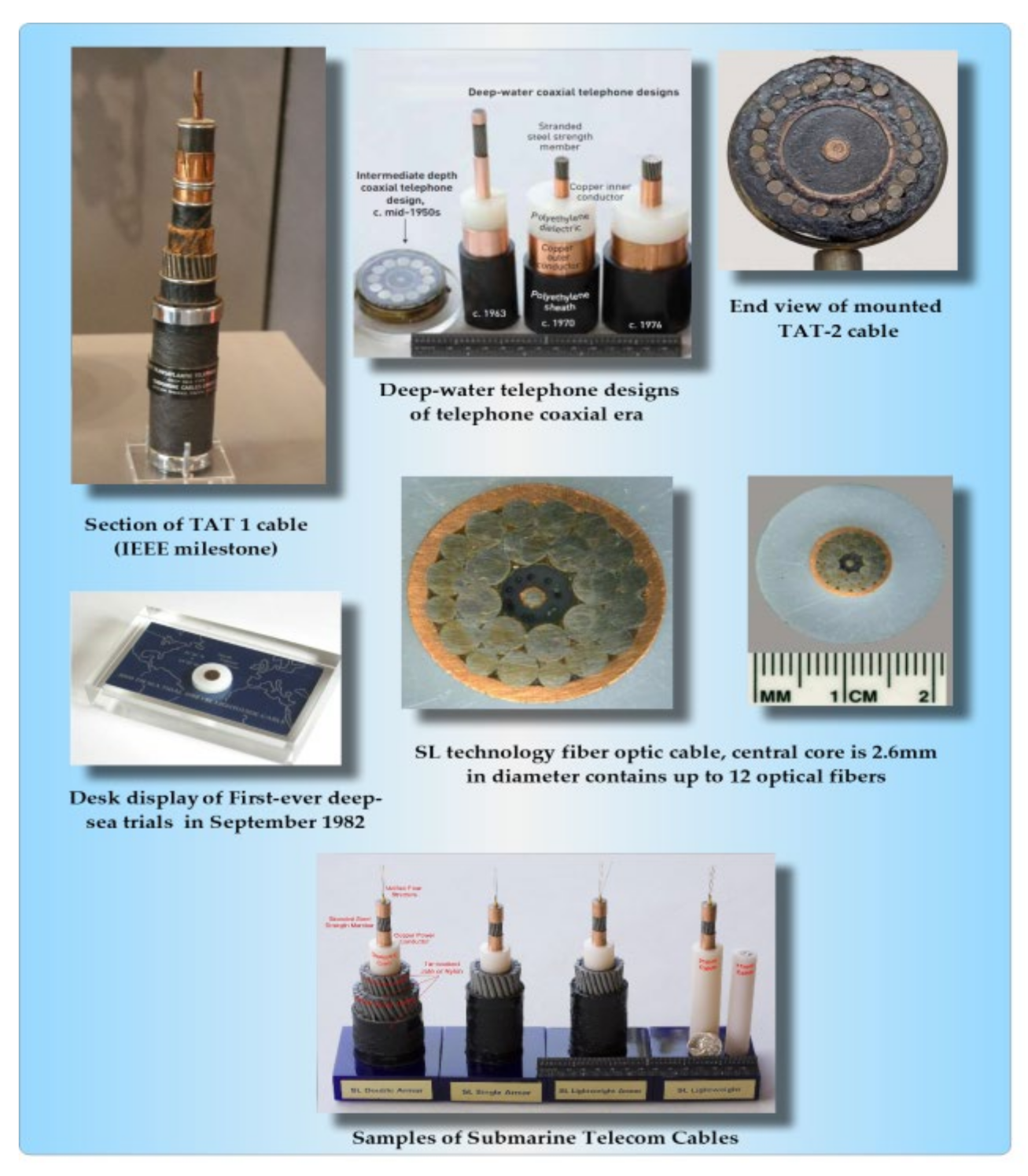
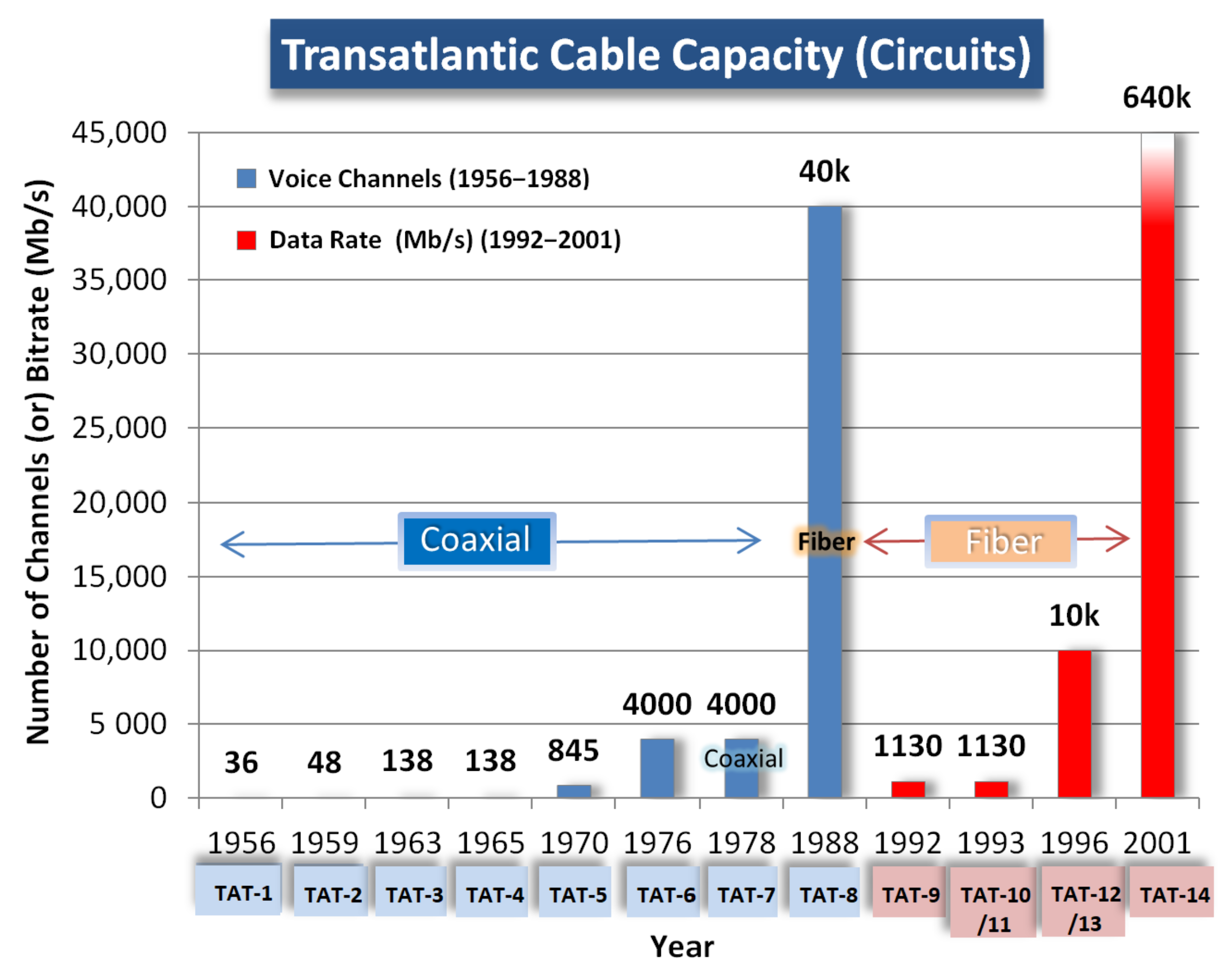
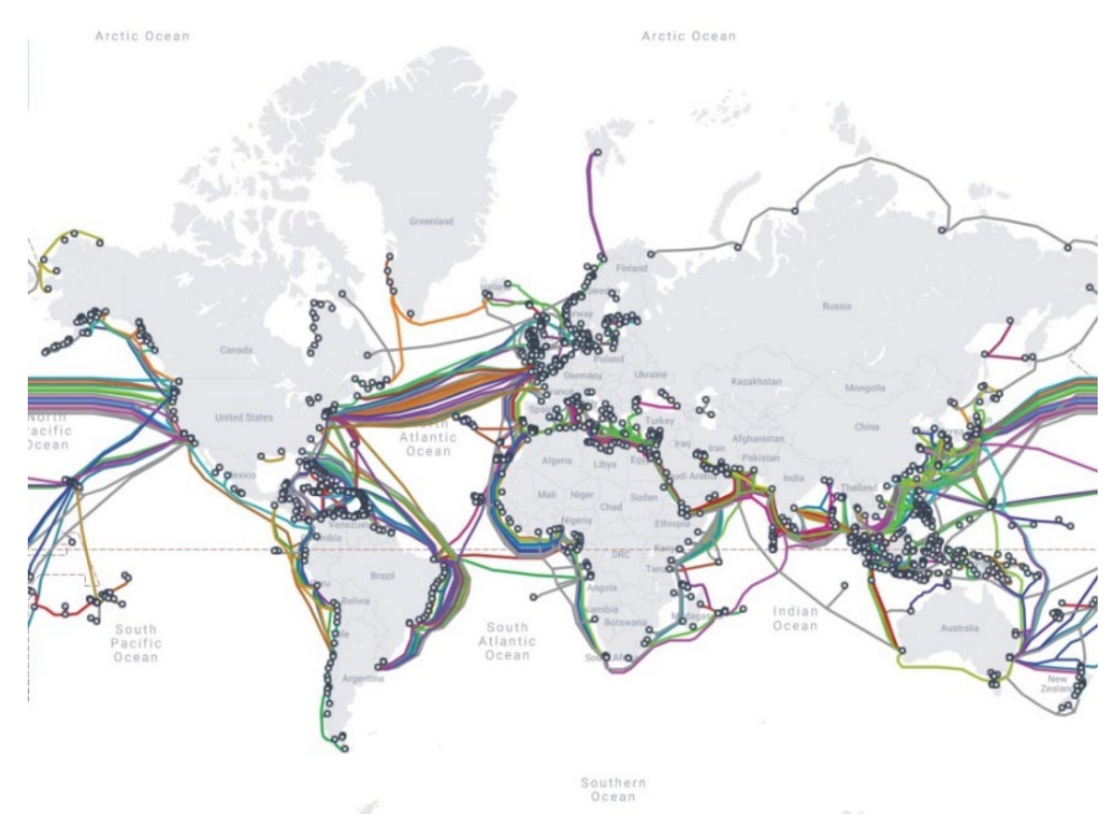
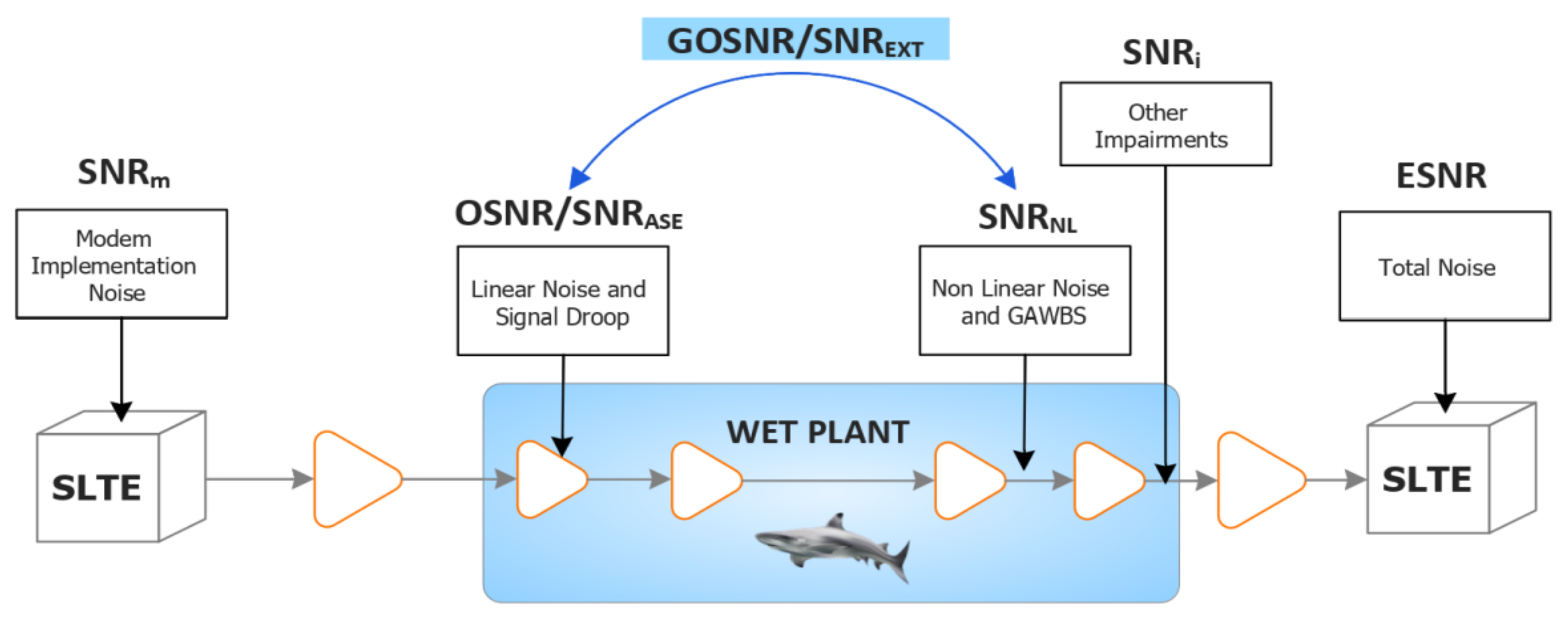
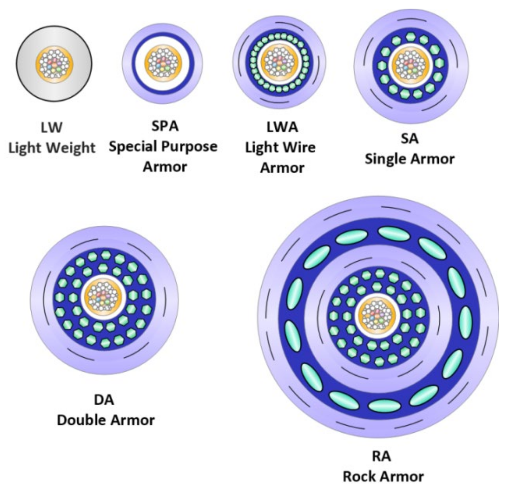
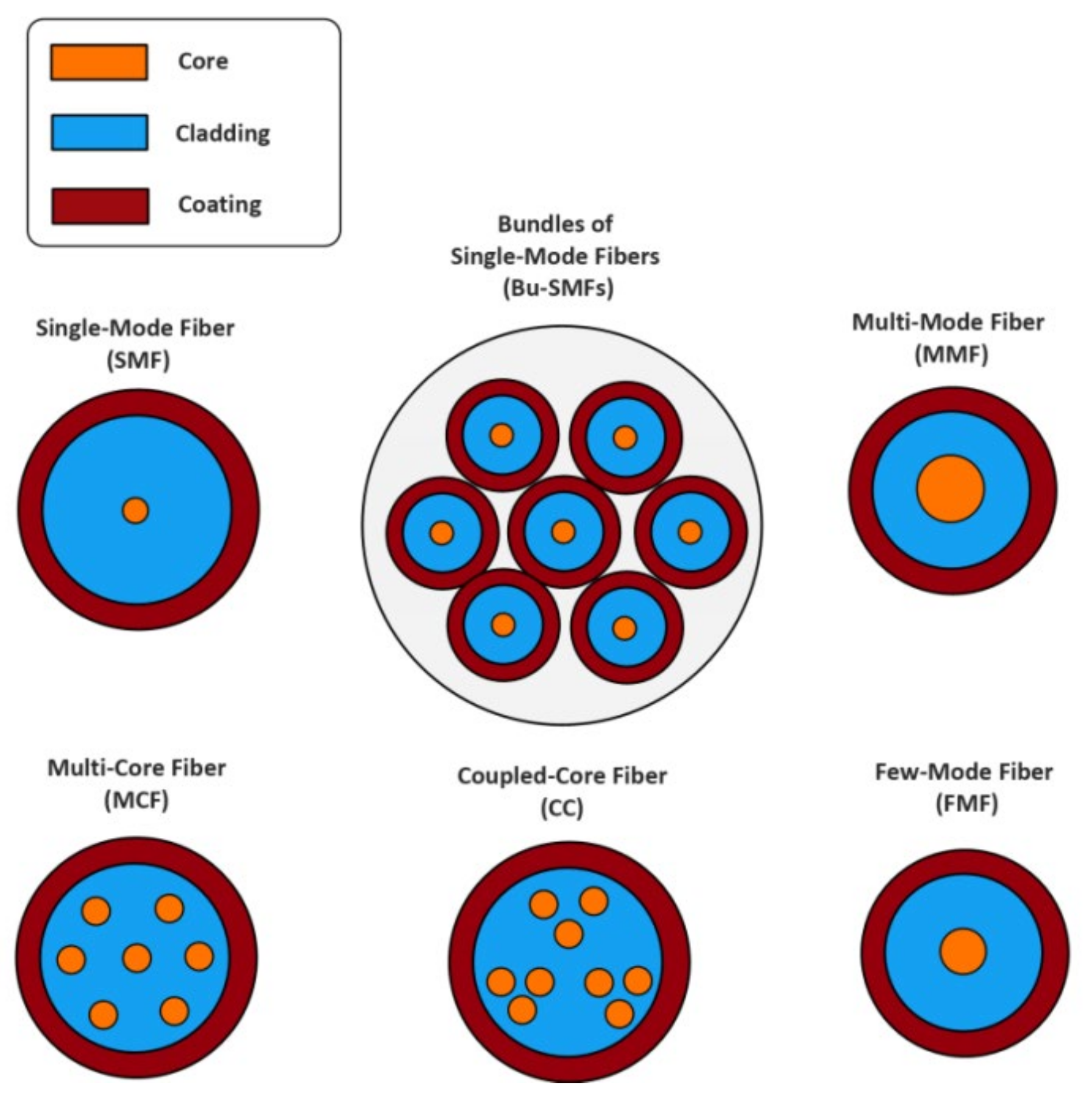
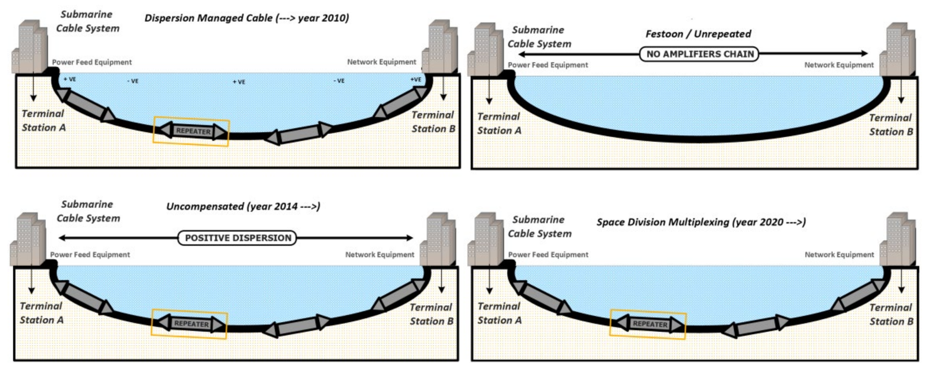
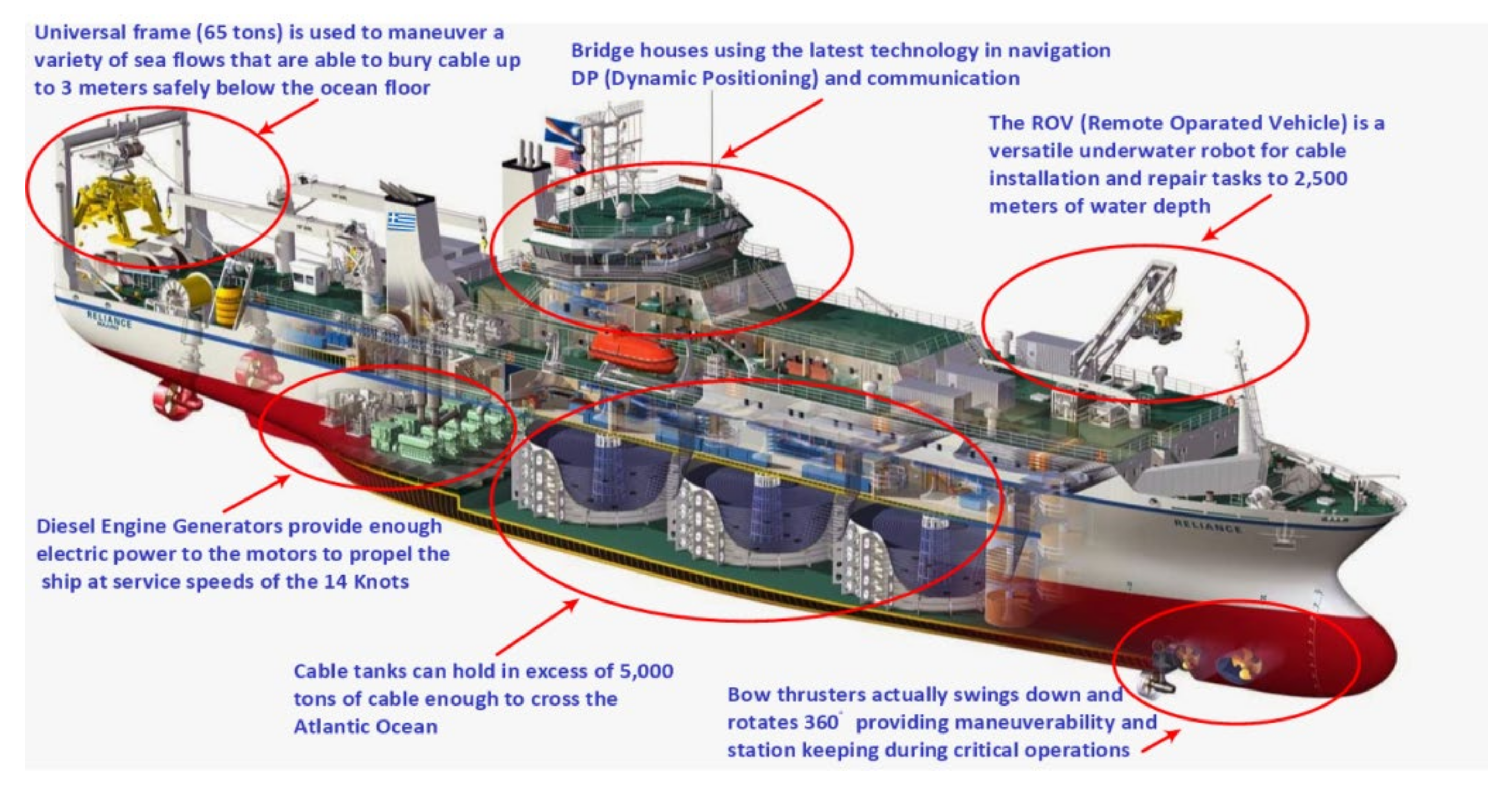
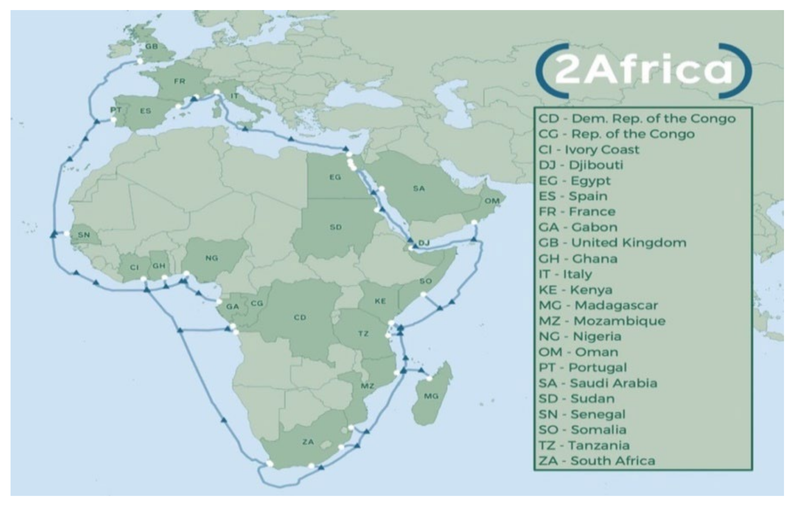
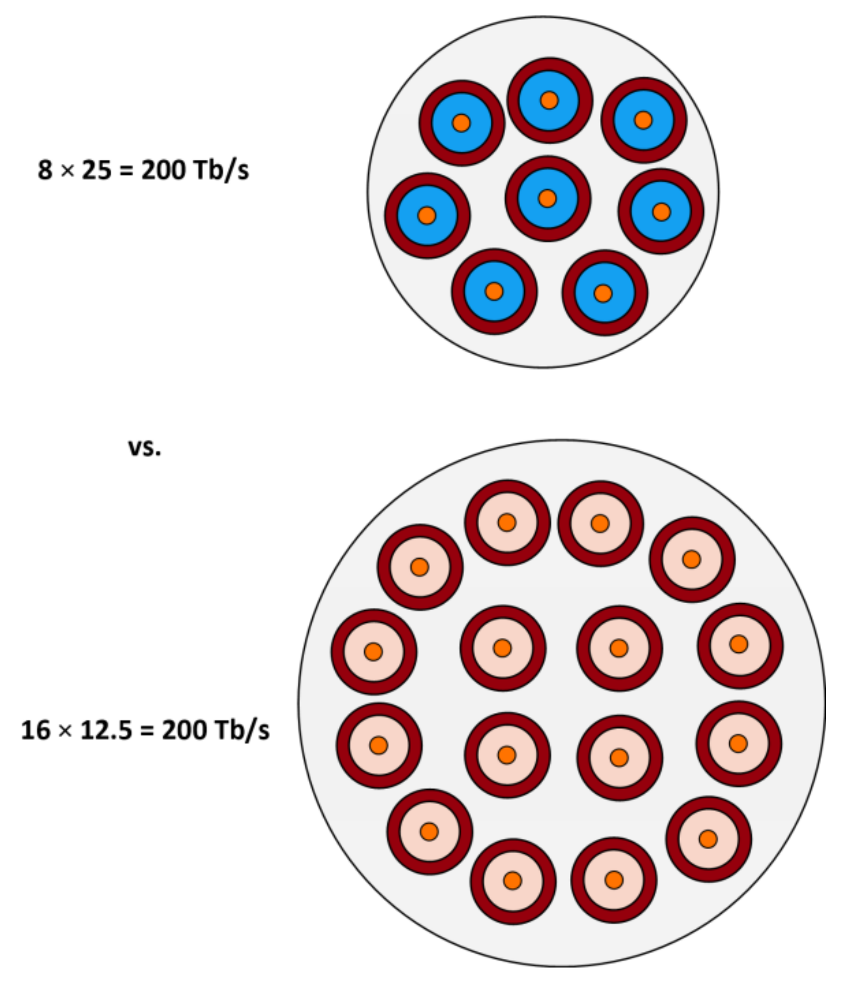
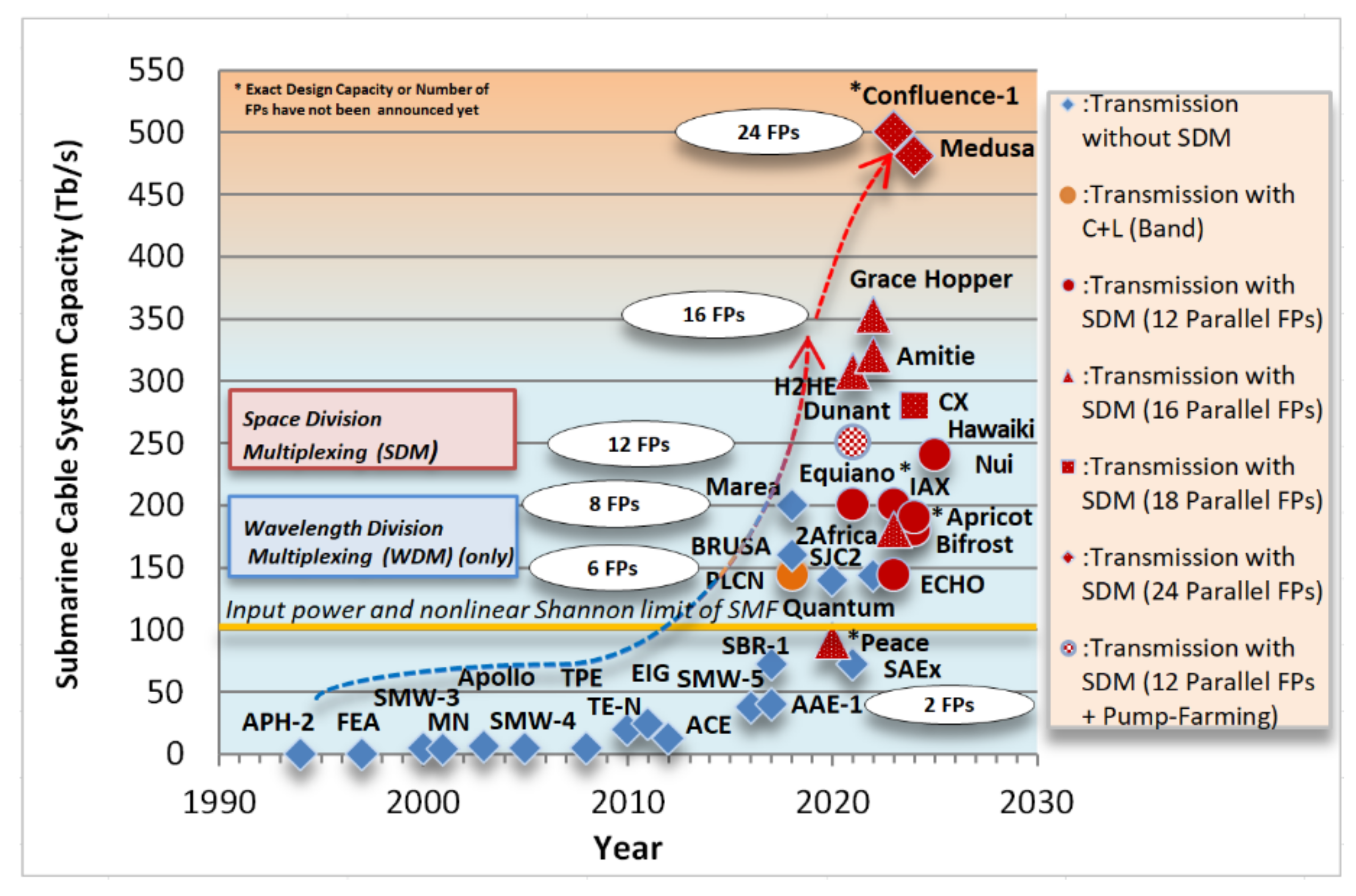
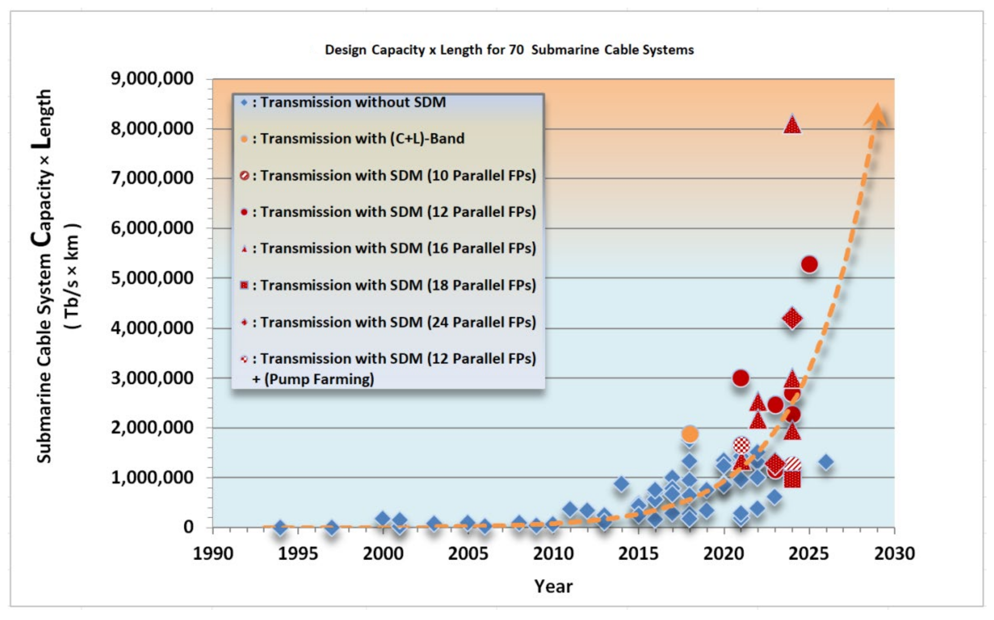
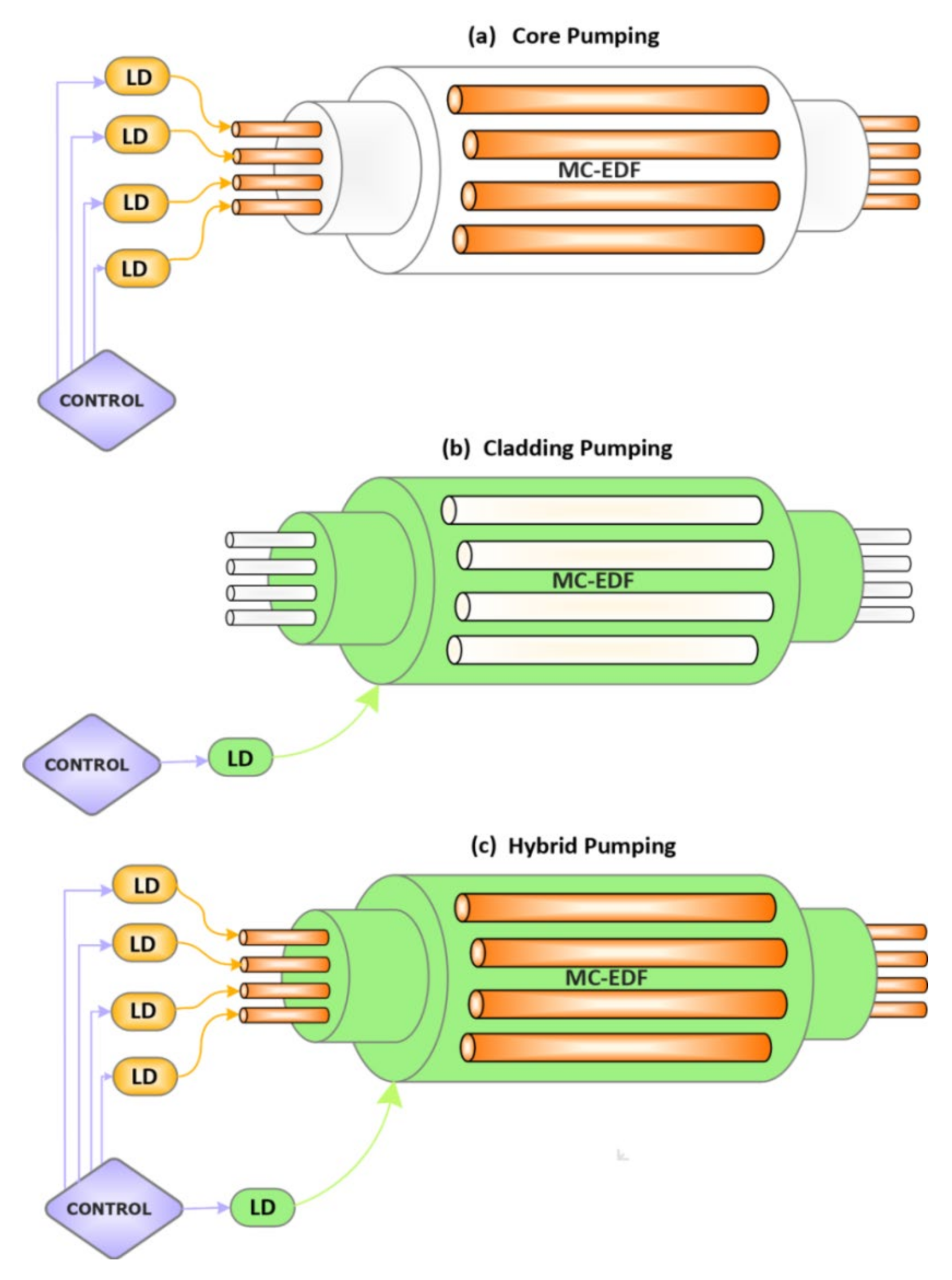
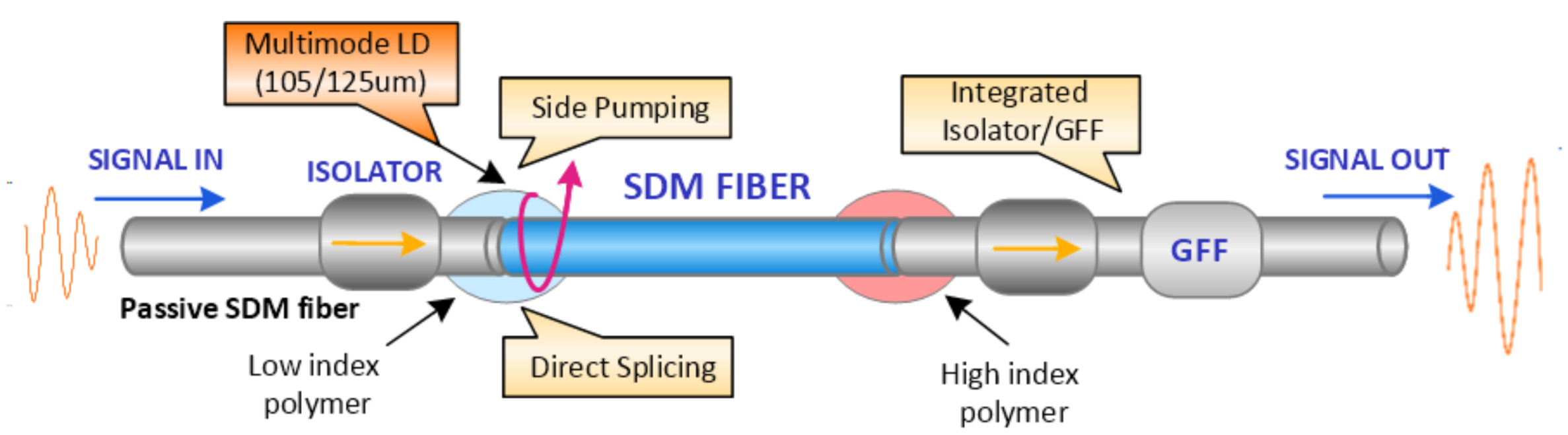
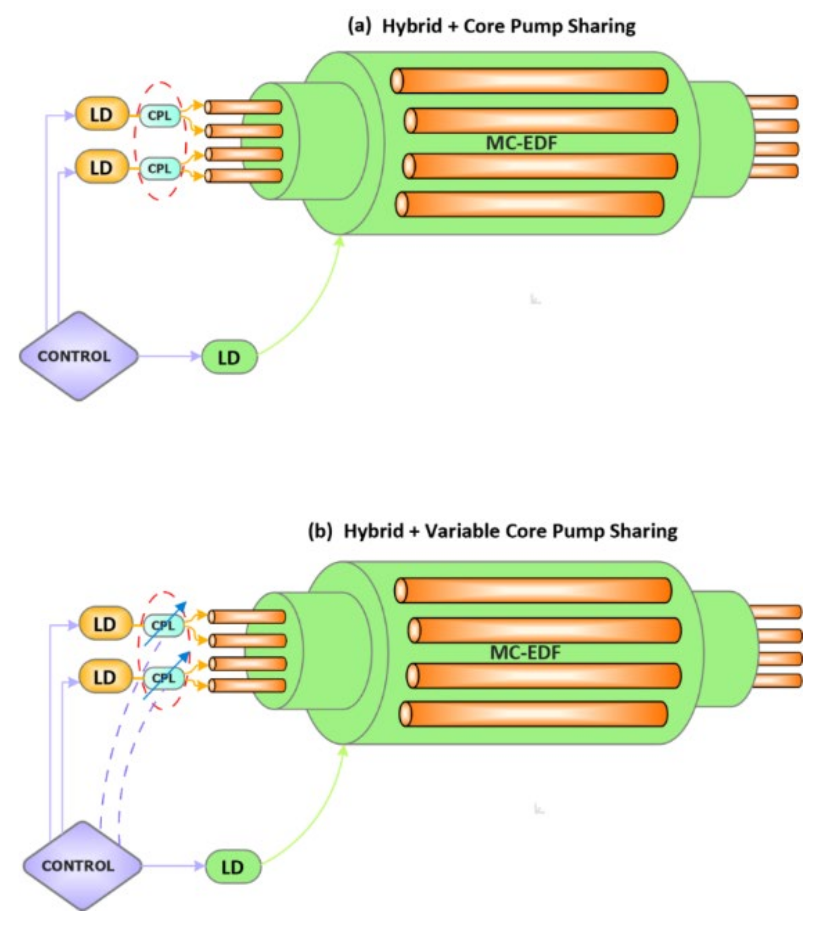
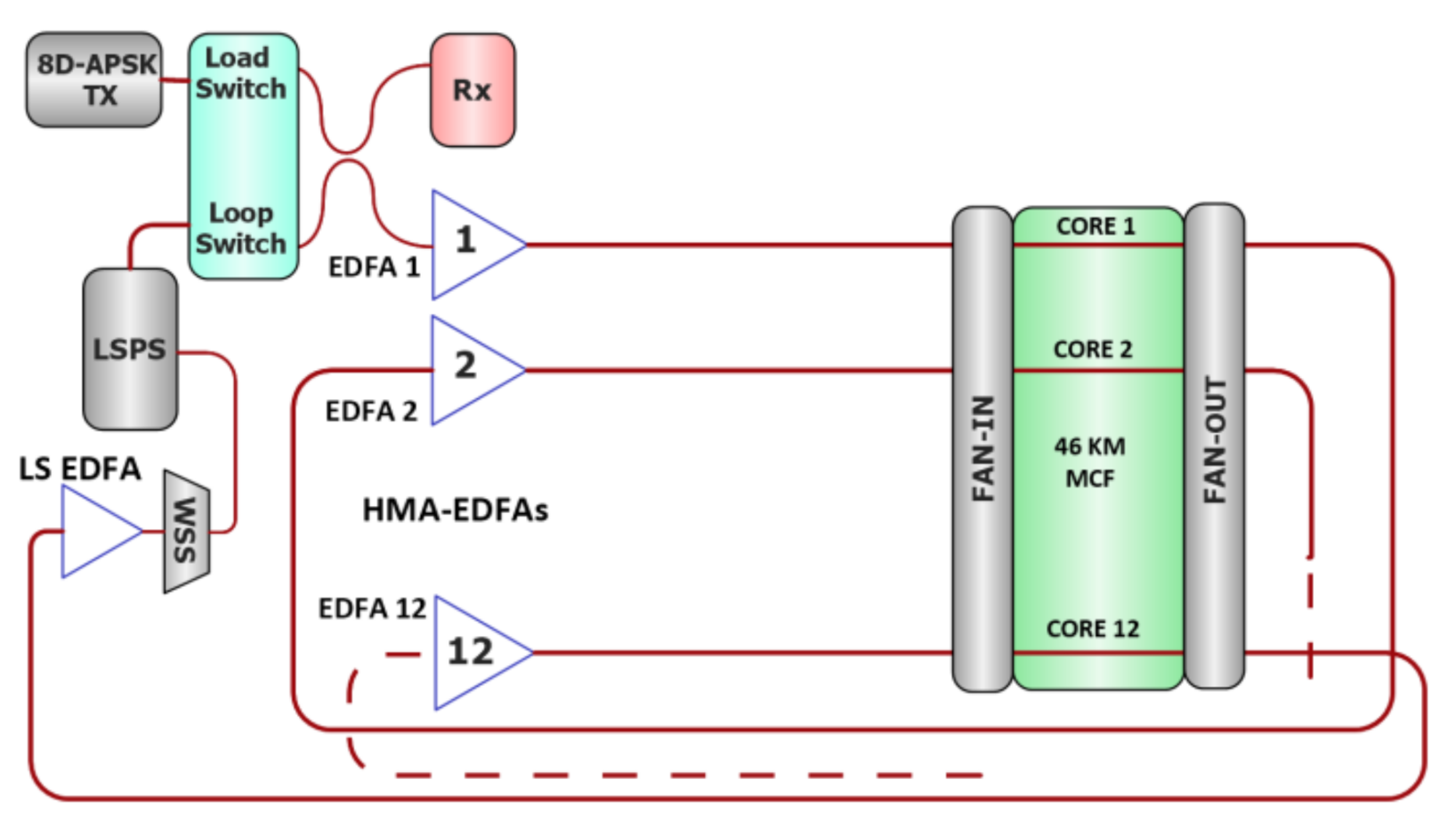
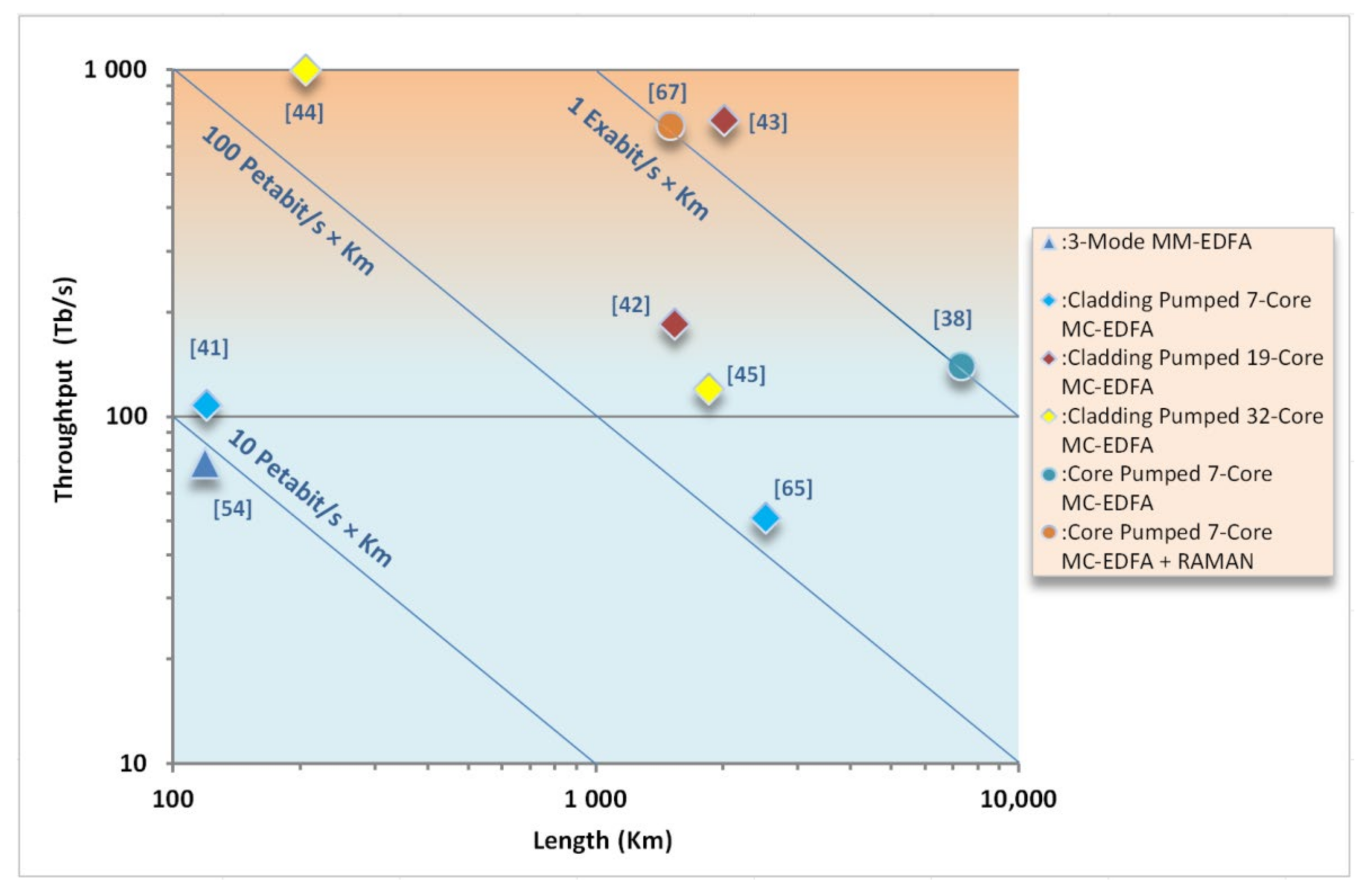
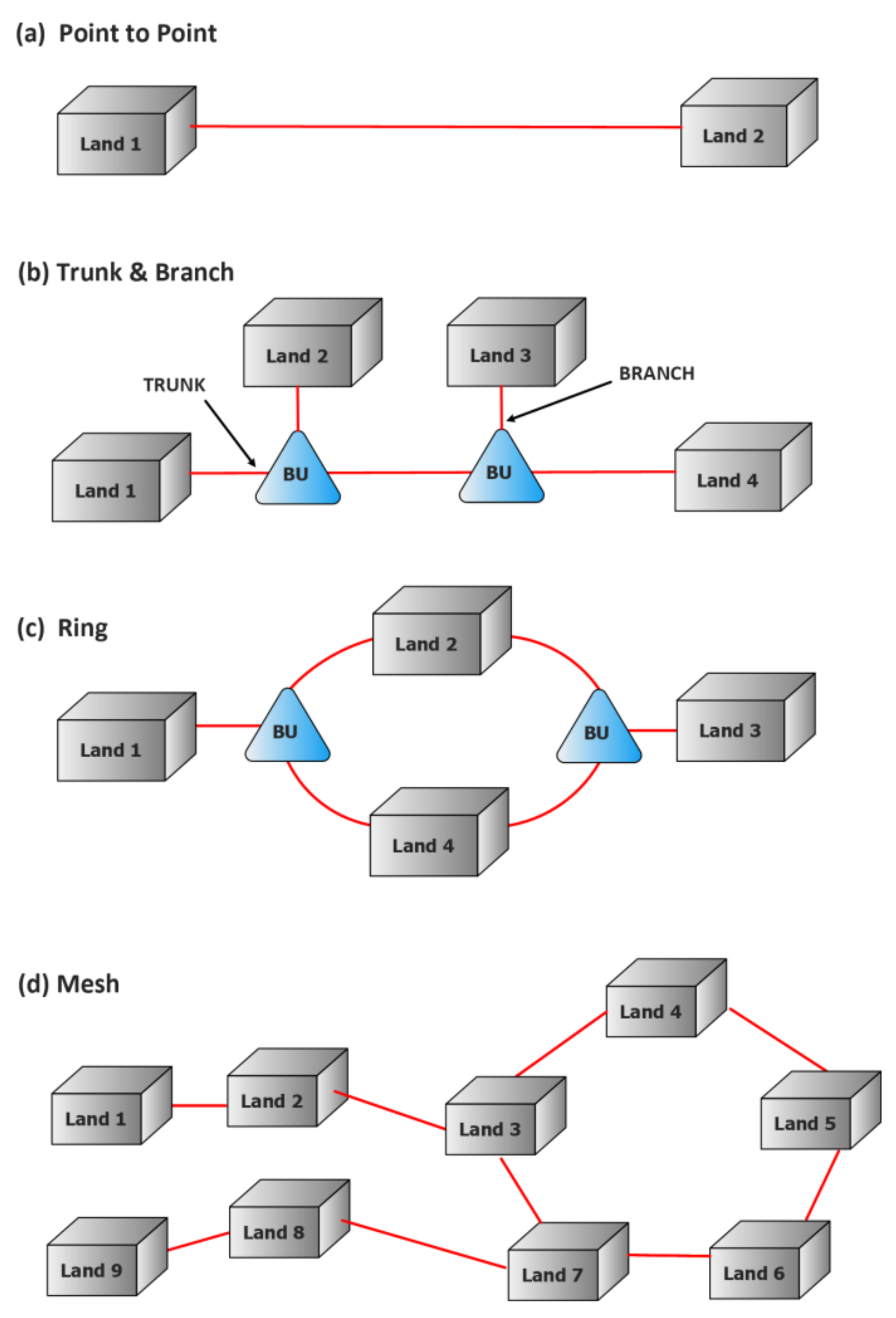
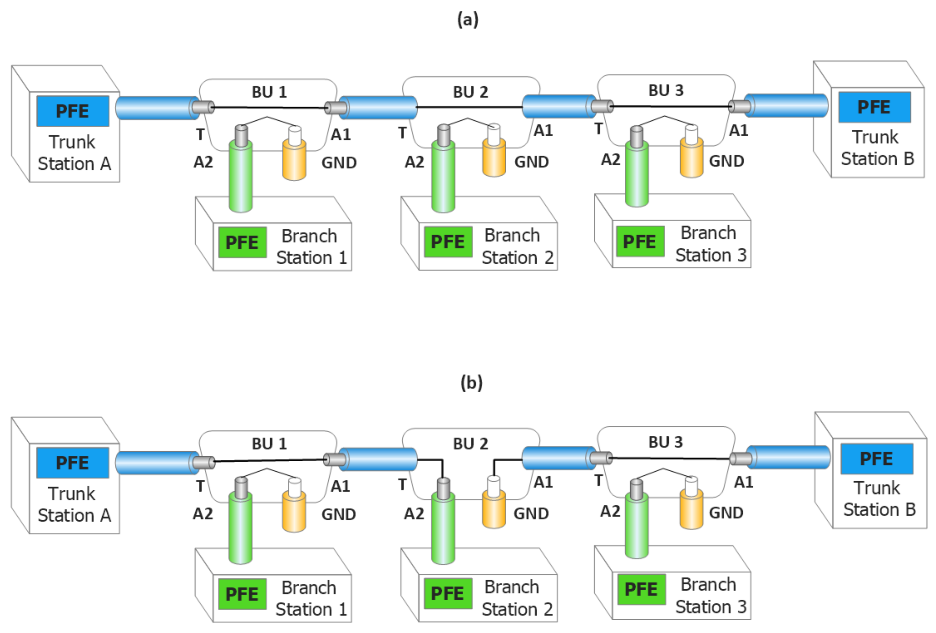
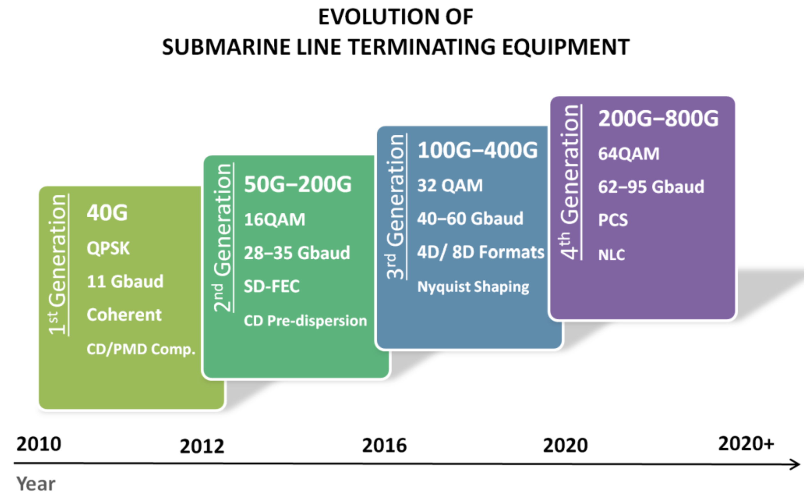
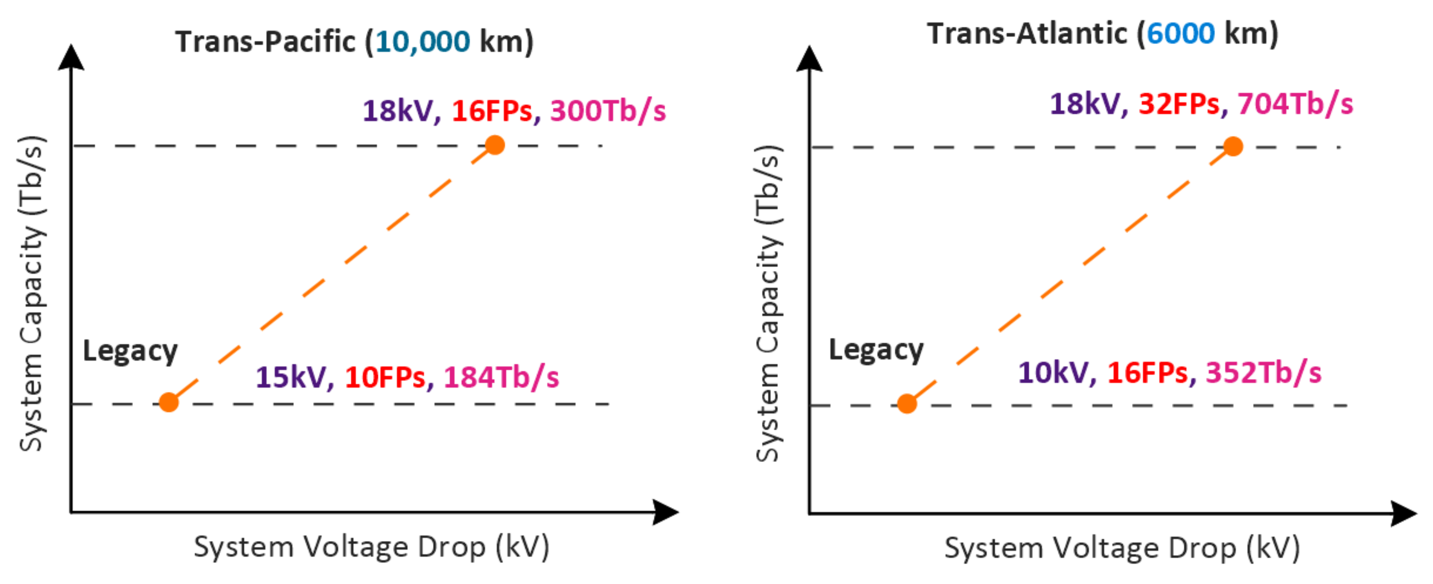
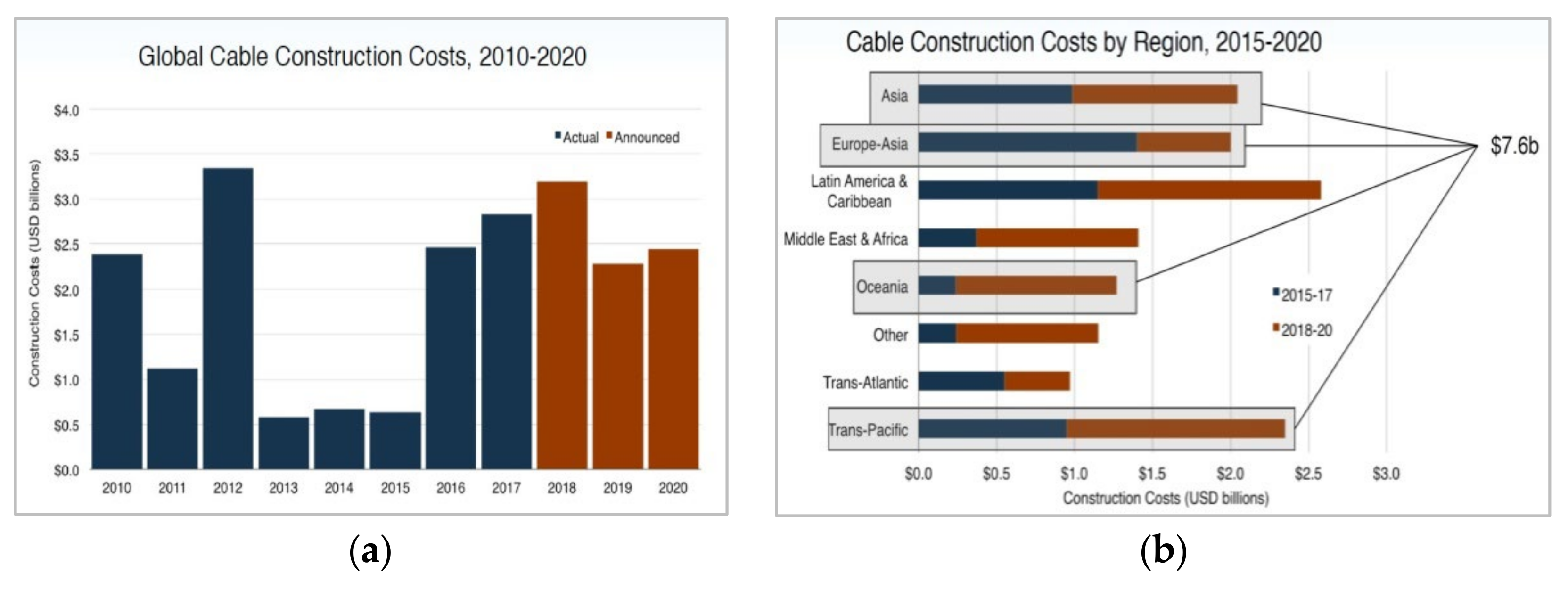
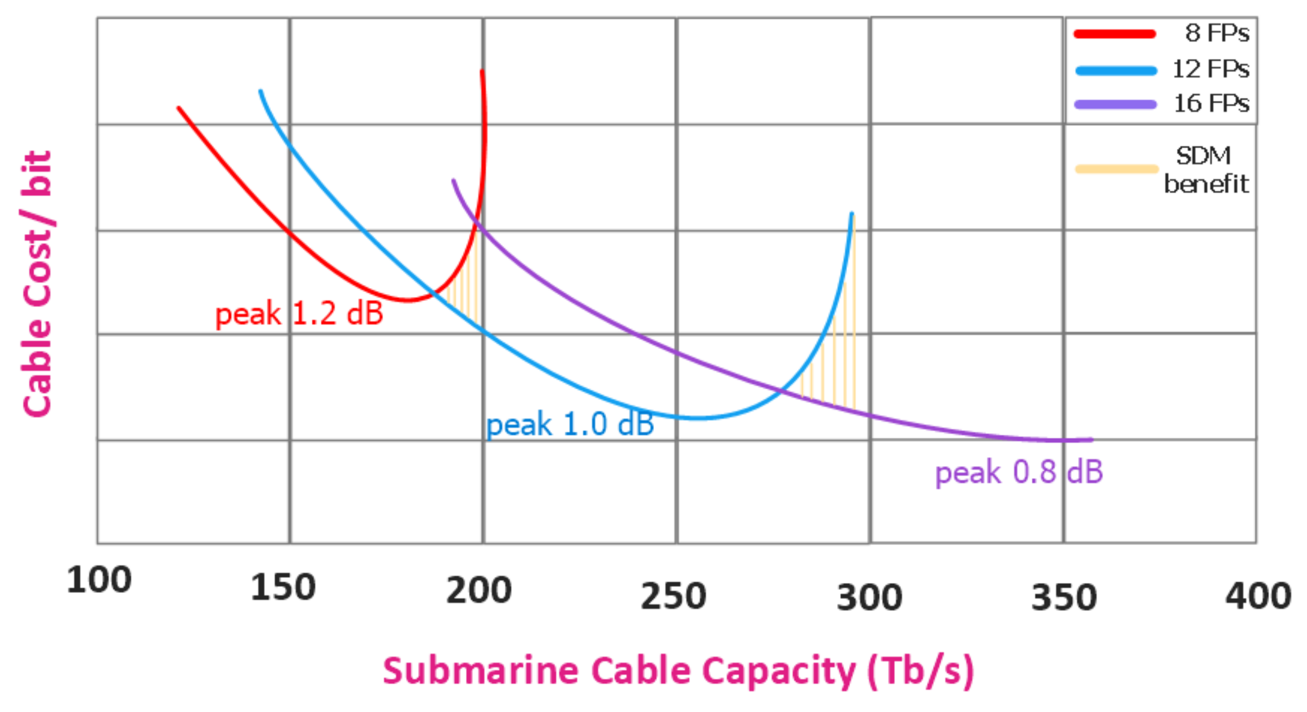
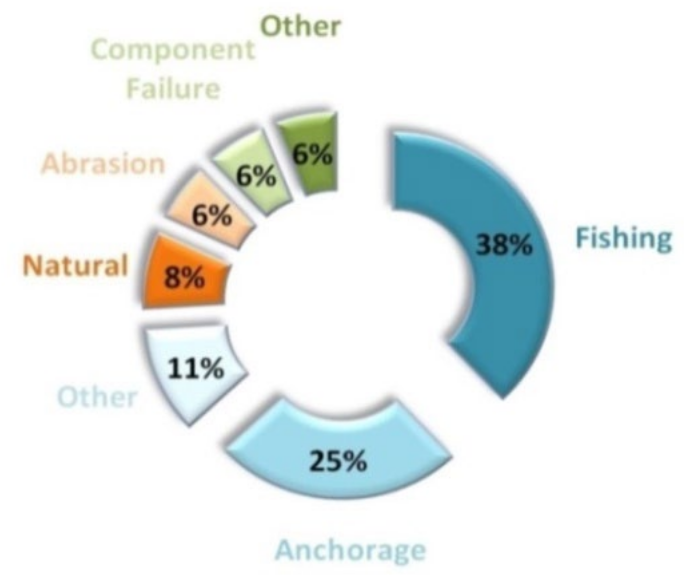
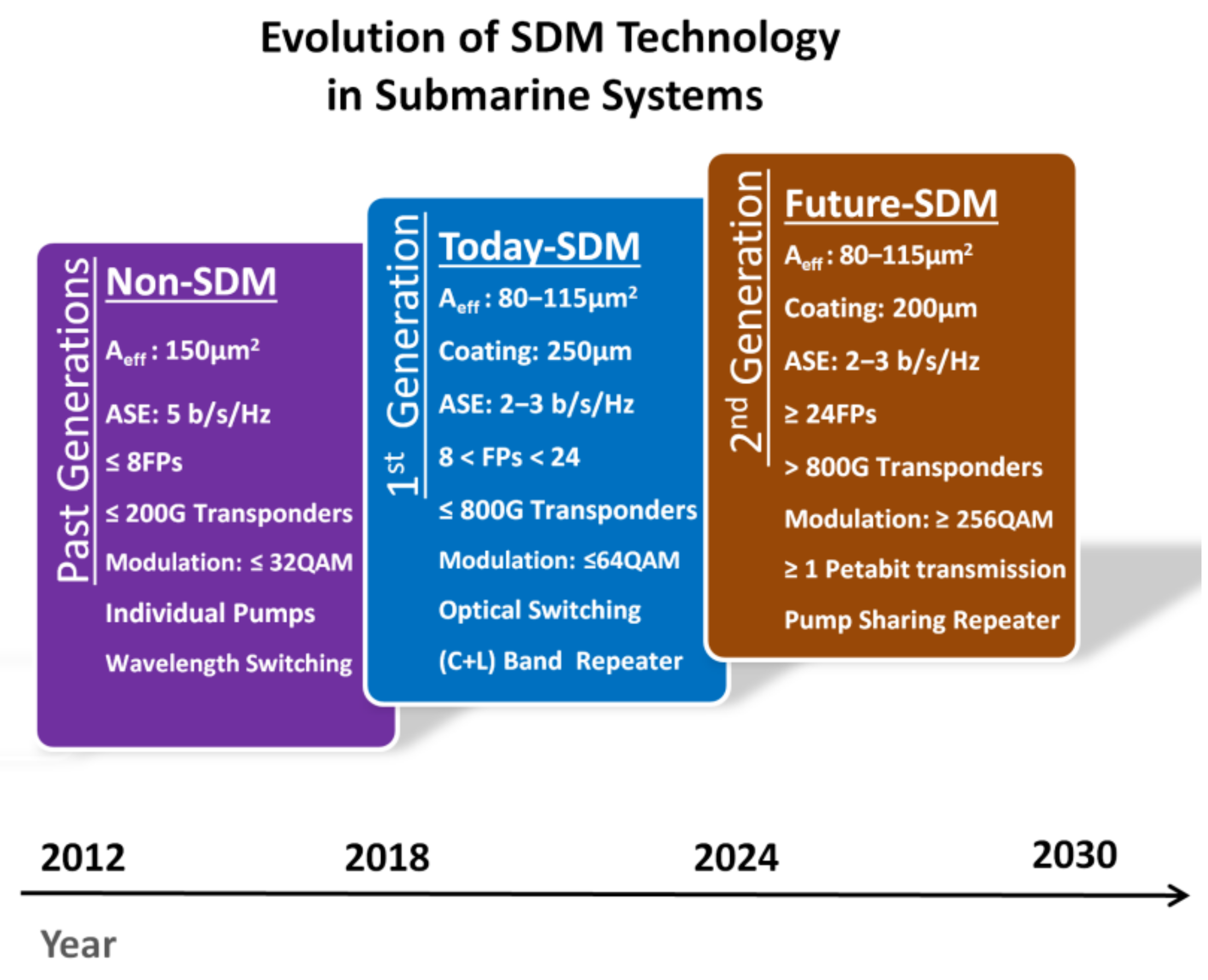
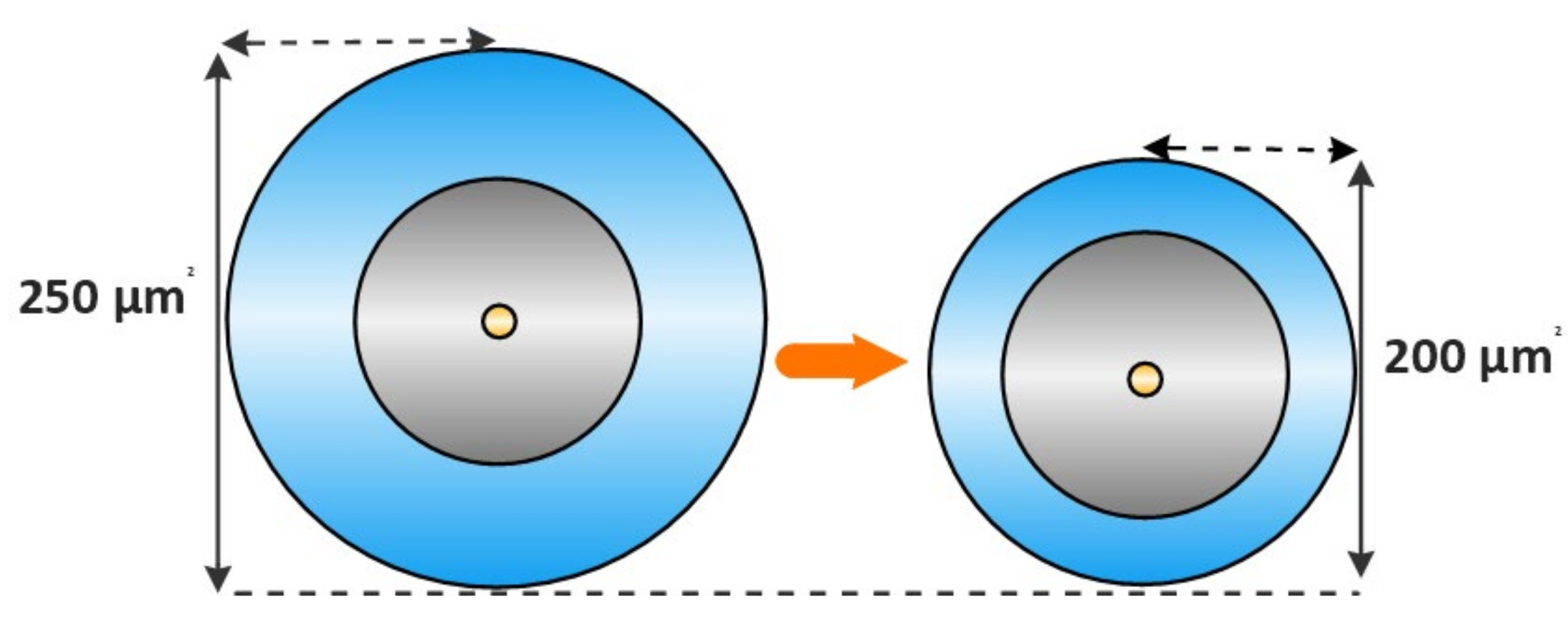
| Year | Cable System | Key Technology | Capacity/Channels | Length |
|---|---|---|---|---|
| 1956–1978 | TAT-1 | First transatlantic * telephone cable, electronic repeaters, hotline | 36 (initial), 48 final telephone channels | 1942 km |
| 1978–1994 | TAT-7 | Employs coaxial cable technology | 4000 (initial), 10,500 final telephone channels | 8910 km |
| 1988–2002 | TAT-8 | First * fiber-optic transatlantic cable | 295.6 Mbit/s traffic or 40,000 phone circuits | 6705 km |
| 1991 | TAT-9 | First system to switch traffic on demand between five landing points | 560 Mbit/s traffic or 80,000 voice circuits | 9305 km |
| 1996–2008 | TAT-12/13 | EDFA technology implemented | 2 × 5 Gb/s | 12,307 km |
| 2001 | TAT-14 | Employs 4 fiber-pair (2 FPs active + 2 FPs backup) WDM technology with direct detection | 3.2 Tb/s | 15,428 km |
| 2008 | TPE | Employs 10 G DWDM technology | 5.12 Tb/s | 17,968 km |
| 2013 | PC-1 | Employs 100 G coherent technology | 8.4 Tb/s | 21,000 km |
| 2018 | PLCN | First submarine cable employs C + L band optical technology | 144 Tb/s | 12,971 km |
| 2021 | Dunant | First submarine cable employs 12 FPs introduces first-generation SDM technology, pump lasers, pump-sharing technology | 250 Tb/s | 6600 km |
| 2021 | H2HE | The world’s first 16-fiber-pair repeated submarine cable system. A milestone in technological innovation | 300 Tb/s | 675 km |
| 2022 | Peace | WSS ROADM BU, 200 G technology, SDM repeater | 90 Tb/s | 15,000 km |
| 2022 | Equiano | First submarine cable employs optical switching at the fiber-pair level (instead of wavelength-level switching) | 200 Tb/s | 15,000 km |
| 2023 | Confluence-1 | First submarine cable employs 24 fiber-pair SDM technology and it will be the largest to be recently installed | >500 Tb/s | 2571 km |
| 2023 | Ellalink | First submarine system to incorporate state-of-the-art ICE6 800 G coherent technology | 100 Tb/s | 6200 km |
| 2023 | Firmina | To be the world’s longest undersea cable capable of maintaining operations with single-end feed power by using 18-kV power technology | N.A | 2500 km |
| 2023–2024 | 2Africa | 2Africa aims to be one of the largest submarine cable systems (46 landing stations, 45,000 km) | 180 Tb/s | 45,000 km |
| 2025 | Arctic. Connect | To be the first transarctic cable system with new innovative cable type and will connect three continents (85% of total world population) | 200 Tb/s | 14,000 km |
| 2024–2025 | Apricot | To incorporate 400 G technology, all new submersible ROADM, flexible bandwidth management based on SDM-based design. | 190 Tb/s | 12,000 km |
| 2025 | SEA-ME-WE-6 | Utilizes SDM cable, supporting up to 24 FPs and incorporates enhanced branching units (eBUs) providing flexible electrical power and optical fiber routing with shore-based telemetry control | 126 Tb/s | 19,200 km |
* Characterized as IEEE milestone.
Table 2.
Compare SDM with other non-SDM solutions [8].
Table 2.
Compare SDM with other non-SDM solutions [8].
| PROS | CONS | |
|---|---|---|
| Lower capacity per FP, as FP becomes consequently the new granularity | Higher quantity of FP used | |
| C-Band | FP switching used to drop a whole FP in a branch | Bigger cable needed to contain all the FPs |
| Easier to sell FP | - | |
| Easier to swap FP | - | |
| - | Less efficient as MUX/DMUX should be used (~1 dB losses) | |
| - | Attenuation is slightly higher in L band (beyond 1600 nm) | |
| (C + L) Band | Limits the number of FP in the cable | Interband effects between C and L bands |
| No need to develop big cable to contain all the FPs | Spectrum sharing needed to sell/swap a portion of a FP | |
| - | Higher cost for BU with WSS to manage spectrum sharing | |
| - | L band amplifier needed |
Table 3.
A taxonomy of SDM-based submarine cable systems [1,2,3,4,5]. RFS: Ready for Service year, SDM 1: First Generation of SDM-based system introduced by (ASN/HMN) supplier.
| Submarine Cable System | RFS | Cable Length (Km) | Capacity (Tb/s) | Technology | Fiber Pairs (FPs) | SDM Nature/Info |
|---|---|---|---|---|---|---|
| Dunant | 2021 | 6400 | 250 | SDM 1 ASN | 12 | Pump Sharing Repeater/(12 FPs) |
| Malbec | 2021 | 2600 | 108 | SDM | 8 | Fiber Count ≥ * 8FPs (8 FPs) |
| Hainan to Hong Kong Express (H2HE) | 2021 | 675 | 307 | SDM 1 HMN | 16 | High Fiber Count (16 FPs) |
| Peace | 2022 | 15,000 | 90 | SDM 1 ASN | † 16 | SDM Repeater/(16 FPs) |
| Equiano | 2022 | 12,000 | 200 | SDM | 12 | Fiber Count ≥ * 8FPs (12 FPs) |
| Grace Hopper | 2022 | 7191 | 352 | SDM | 16 | High Fiber Count (16 FPs) |
| Amitie | 2022 | 6792 | 320 | SDM | 16 | High Fiber Count (16 FPs) |
| 2Africa | 2023 | 45,000 | 180 | SDM 1 ASN | 16 | Fiber Count ≥ * 8FPs/(12FPs) |
| ECHO | 2023 | 17,184 | 144 | SDM | 12 | Fiber Count ≥ * 8FPs (12 FPs) |
| IAX | 2023 | 5791 | 200 | SDM | † 12 | Fiber Count ≥ * 8FPs (12 FPs) |
| Confluence-1 | 2023 | 2571 | ≥500 † | SDM | 24 | Ultrahigh Fiber Count (24 FPs) |
| Firmina | 2023 | 2500 | N.A | SDM | 12 | Fiber Count ≥ * 8FPs (12 FPs) |
| Bifrost | 2024 | 15,000 | 180 | SDM 1 ASN | 12 | Fiber Count ≥ * 8FPs (12 FPs) |
| Apricot | 2024 | 12,000 | 190 | SDM | † 16–20 | Fiber Count ≥ (12 FPs), † (16–20 FPs) |
| IEX | 2024 | 9775 | 200 | SDM | † 16 | High Fiber Count (16 FPs) |
| Medusa | 2024 | 8760 | 480 | SDM | 24 | Ultrahigh Fiber Count (24 FPs) |
| Blue Raman | 2024 | 7500 | 400 † | SDM | 16 | High Fiber Count (16 FPs) |
| Caribbean Express (CX) | 2024 | 3472 | 280 | SDM | 18 | Very High Fiber Count (18 FPs) |
| Hawaiki Nui | 2025 | 22,000 | 240 | SDM | 12 | Fiber Count ≥ * 8FPs (12 FPs) |
| Sea-We-Me 6 | 2025 | 19,200 | 126 | SDM | 10 | Fiber Count ≥ * 8FPs (10 FPs) |
* 8FPs is the limit of previous technologies cable systems, † expected/predicted.
Table 4.
A comparison between Traditional and SDM submarine cables [13].
Table 4.
A comparison between Traditional and SDM submarine cables [13].
| Subsea Component | SDM Cable | Traditional Cable |
|---|---|---|
| Submarine Cable | High Count of FPs (12, 16 FPs and more in future) | Limited number of FPs (6 FPs and maximum 8 FPs) |
| Fiber Effective Area (Aeff) | Low effective area, Aeff 110–80 μm2, att. 0.155 dB/km | High effective area, Aeff 150–125 μm2, att. 0.15 dB/km |
| Repeater | Low power repeaters: (+14 to 20 dBm) | Very high power repeaters: (>+20 dBm) |
| Repeater Type | Repeater pump farming | Each fiber has own laser pumps |
| Branching Unit ROADMs | Fiber pair switching in (BUs) | No fiber pair switching in (BUs) |
| OSNR | Low OSNR | High OSNR |
| Modulation Formats | PCS (probabilistic constellation shaping) | BPSK, QPSK, 8-QAM and 16-QAM |
| C + L Band Technology | Currently only C-Band | C + L Band supported up to 144 channels per FP |
| PFE | Same PFE, capacity can be increased | Same PFE |
| Topology | Submarine Cable System | Cable Length (Km) | Landing Points | Number of Operators |
|---|---|---|---|---|
| SeaMeWe-3 | 39,000 | 39 | 52 | |
| FLAG Europe-Asia (FEA) | 28,000 | 17 | Global Cloud Xchange | |
| AsiaAfrica Europe-1 (AAE-1) | 25,000 | 20 | 18 | |
| SeaMeWe-4 | 20,000 | 16 | 16 | |
| SeaMeWe-5 | 20,000 | 18 | 18 | |
| Africa Coast to Europe (ACE) | 17,000 | 22 | 20 | |
| ** SDM Repeater | Peace | 15,000 | 14 | Peace Cable International Network Co., Ltd. |
| EuropeIndia Gateway (EIG) | 15,000 | 12 | 16 | |
| Southern Cross NEXT | 13,700 | 7 | Southern Cross Cable | |
| Polar Express | 12,650 | 10 | Russian Government | |
| BRUSA | 11,000 | 4 | Telxius | |
| Africa-1 | 10,000 | 10 | Etisalat UAE | |
| South Atlantic Express (SAEx) | 10,000 | 5 | SAEx International | |
| Trunk&Branch | Amitie | 6792 | 5 | 3 |
| TE North/TGN-Eurasia/… | 3634 | 4 | 6 | |
| Malbec | 2600 | 3 | Facebook, GlobeNet | |
| * SDM Technology | 2Africa | 45,000 | 29 | 8 |
| * SDM Technology | Hawaiki Nui | 22,000 | 13 | Hawaiki Submarine Cable |
| * SDM Technology | ECHO | 17,184 | 6 | 2 |
| * SDM Technology | Bifrost | 15,000 | 5 | 3 |
| * SDM Technology | Equiano | 12,000 | 7 | |
| * SDM Technology | Apricot | 12,000 | 4 | 7 |
| * SDM Technology | Medusa | 8760 | 16 | AFRIX Telecom |
| * SDM Technology | Grace Hopper | 7191 | 3 | |
| * SDM Technology | Amitie | 6792 | 3 | 5 |
| * SDM Technology | Caribbean Express (CX) | 3472 | 11 | OceanNetworks (ONI) |
| * SDM Technology | Confluence-1 | 2571 | 5 | Confluence Networks |
| EAC-C2C | 36,500 | 16 | Telstra | |
| Mesh | Trans-Pacific Express (TPE) | 17,000 | 6 | 7 |
| MedNautilus Submarine System | 7000 | 7 | Telecom Italia Sparkle | |
| Apollo | 13,000 | 2 | Vodafone | |
| CAP-1 | 12,000 | 2 | Amazon Web Services, Facebook | |
| Seabras-1 | 10,800 | 2 | Seaborn Networks, Telecom Italia Sparkle | |
| Point-to-Point | MAREA | 6605 | 2 | Facebook, Microsoft, Telxius |
| INDIGO-Central | 4850 | 2 | 5 | |
| JGA-N | 2600 | 2 | RTI | |
| BlueMed | 1000 | 2 | Telecom Italia Sparkle | |
| * SDM Technology | Dunant | 6400 | 2 | |
| Japan-U.S. Cable Network (JUS) | 22,682 | 6 | 24 | |
| Pacific Crossing-1 (PC-1) | 22,900 | 4 | NTT | |
| Ring | TPC-5 | 22,560 | 6 | 13 |
| Atlantic Crossing-1 (AC-1) | 14,301 | 4 | Lumen |
* The cable system incorporates the SDM technology; ** The cable system incorporates at least one SDM-based device (e.g., SDM repeater).
Table 6.
Comparison of transmission experiments at transoceanic distances.
| Reference | C (Tb/s) | L (Km) | ↓ SE (b/s/Hz) | Technology |
|---|---|---|---|---|
| [26] | 71.65 | 6970 | 7.36 | non-SDM |
| [26] | 70.46 | 7600 | 7.23 | non-SDM |
| [16] * | 24.6 | 6664 | 6.21 | non-SDM |
| [27] | 30.58 | 6630 | 6.10 | non-SDM |
| [28] | 105.1 | 14,350 | 3.20 | SDM |
| [15] | 8.12 | 9750 | 3.20 | SDM |
| [14] | 12 | 17,680 | 2.91 | SDM |
| [29] | 9.0 | 15,050 | 2.00 | SDM |
* Review the deployment of MAREA cable system.
Table 7.
Cladding and Core-Pumping features.
| Core Pumping | Cladding Pumping | |
|---|---|---|
| Mode | Single-Mode | Multi-Mode |
| Pump Power (W) | Low (−5) | High (−30) |
| Wavelength(λ) (nm) Direction | 1480 Backward | 980 Forward |
| Number of Pump LD’s | N-Cores | 1 |
| Presence of Cooling subsystem | Yes | No |
Table 8.
Available Pumping Schemes [13].
Table 8.
Available Pumping Schemes [13].
| Pumping Scheme | Acronym | Core Pumping | Clad Pumping | Comments |
|---|---|---|---|---|
| Individual Core Pumping | ICP | Yes | No | Reference |
| Shared Core Pumping | SCP | Yes | No | With 3 dB coupler |
| Variable Shared Core Pumping | VSCP | Yes | No | With tunable coupler |
| Common Cladding Pumping | CCP | No | Yes | Need of core attenuation |
| Hybrid with Individual Core Pumping | HICP | Yes | Yes | - |
| Hybrid with Shared Core Pumping | HSCP | Yes | Yes | With 3 dB coupler |
| Hybrid with Variable Shared Core Pumping | HVSCP | Yes | Yes | With tunable coupler |
Publisher’s Note: MDPI stays neutral with regard to jurisdictional claims in published maps and institutional affiliations. |
© 2022 by the authors. Licensee MDPI, Basel, Switzerland. This article is an open access article distributed under the terms and conditions of the Creative Commons Attribution (CC BY) license (https://creativecommons.org/licenses/by/4.0/).
Share and Cite
MDPI and ACS Style
Papapavlou, C.; Paximadis, K.; Uzunidis, D.; Tomkos, I. Toward SDM-Based Submarine Optical Networks: A Review of Their Evolution and Upcoming Trends. Telecom 2022, 3, 234-280. https://0-doi-org.brum.beds.ac.uk/10.3390/telecom3020015
AMA Style
Papapavlou C, Paximadis K, Uzunidis D, Tomkos I. Toward SDM-Based Submarine Optical Networks: A Review of Their Evolution and Upcoming Trends. Telecom. 2022; 3(2):234-280. https://0-doi-org.brum.beds.ac.uk/10.3390/telecom3020015
Chicago/Turabian StylePapapavlou, Charalampos, Konstantinos Paximadis, Dimitrios Uzunidis, and Ioannis Tomkos. 2022. "Toward SDM-Based Submarine Optical Networks: A Review of Their Evolution and Upcoming Trends" Telecom 3, no. 2: 234-280. https://0-doi-org.brum.beds.ac.uk/10.3390/telecom3020015