
Design Procedure of a Frequency Reconfigurable Metasurface Antenna at mmWave Band


Department of Electrical, Computer, and Telecommunications Engineering, Faculty of Engineering, Botswana International University of Science and Technology, Private Bag 16, Palapye 10071, Botswana
*
Author to whom correspondence should be addressed.
Telecom 2022, 3(2), 379-395; https://0-doi-org.brum.beds.ac.uk/10.3390/telecom3020020
Submission received: 10 March 2022
/
Revised: 13 April 2022
/
Accepted: 20 April 2022
/
Published: 9 June 2022
Abstract
:The use of the millimeter wave (mmWave) spectrum and further exploration of sub-mmWave has led to a new era in wireless communication, as the need for higher data rates grows. High frequencies, on the other hand, incur a higher path loss, requiring an increase in antenna gain requirements. Metasurfaces, which emerge as a promising technology for mitigating path loss effects by utilizing two dimensional (2D) arrays of engineered meta-atoms resembling metamaterials that control the surface’s electromagnetic response have been introduced. Currently, metasurfaces are primarily considered as passive reflecting devices in wireless communications, assisting conventional transceivers in shaping propagation environments. This paper presents an alternative application of metasurfaces for wireless communications as active reconfigurable antennas for next generation transceivers. A framework that demonstrates the design process of a metasurface antenna structure was introduced and further used to design a 4 × 4 array and its reconfigurable counterpart. In contrast to conventional phased array antennas, a reconfigurable metasurface (RMS) antenna does not require phase-shifters and amplifiers, which leads to reduced cost. Instead, each individual element achieves reconfigurability by shifting the resonating frequency using semiconductor devices such as PIN diodes. The proposed metasurface antenna is designed to operate at a frequency of 28 GHz and 40 GHz. In addition, an increase in gain and directivity was observed when diodes were added to the metasurface antenna array. However, due to PIN diodes being connected to metallic strips in the metasurface antenna array, loss can occur due to power dissipation, which results in a decrease in radiation efficiency.
1. Introduction
The under-utilized mmWaves spectrum gave researchers an opportunity to investigate and exploit this band with the aim to curb issues on bandwidth and channel capacity associated with 5G and 6G technologies [1]. Consequently, new wireless communication technologies are emerging, including mmWaves utilization and further exploration of sub-mmWaves, as the need for higher data rates grows [2,3,4,5]. However, high frequencies introduce high path loss, which results in the need for improved hardware designs and performance such as antenna gain requirements [2]. One enabling technology is massive multiple-input multiple-output (mMIMO), which is developed to increase the throughput and spectral efficiency by deploying thousands of antennas at a base station [6,7]. In particular, mMIMO aims to have more antenna elements at the access points than the number of active user equipment in any cell at any point in time. This induces more orthogonal channels and consequently achieves high spectral efficiency. Despite these benefits of mMIMO, implementing large scale antenna arrays in practice has proven to be a challenge [8]. Among these challenges are high fabrication cost, increased power consumption, and constrained physical size [9,10]. With significantly improved cost and manufacturing efficiency, metasurface antennas are emerging as an alternative to conventional electronic scanned antennas [8,11,12,13,14].
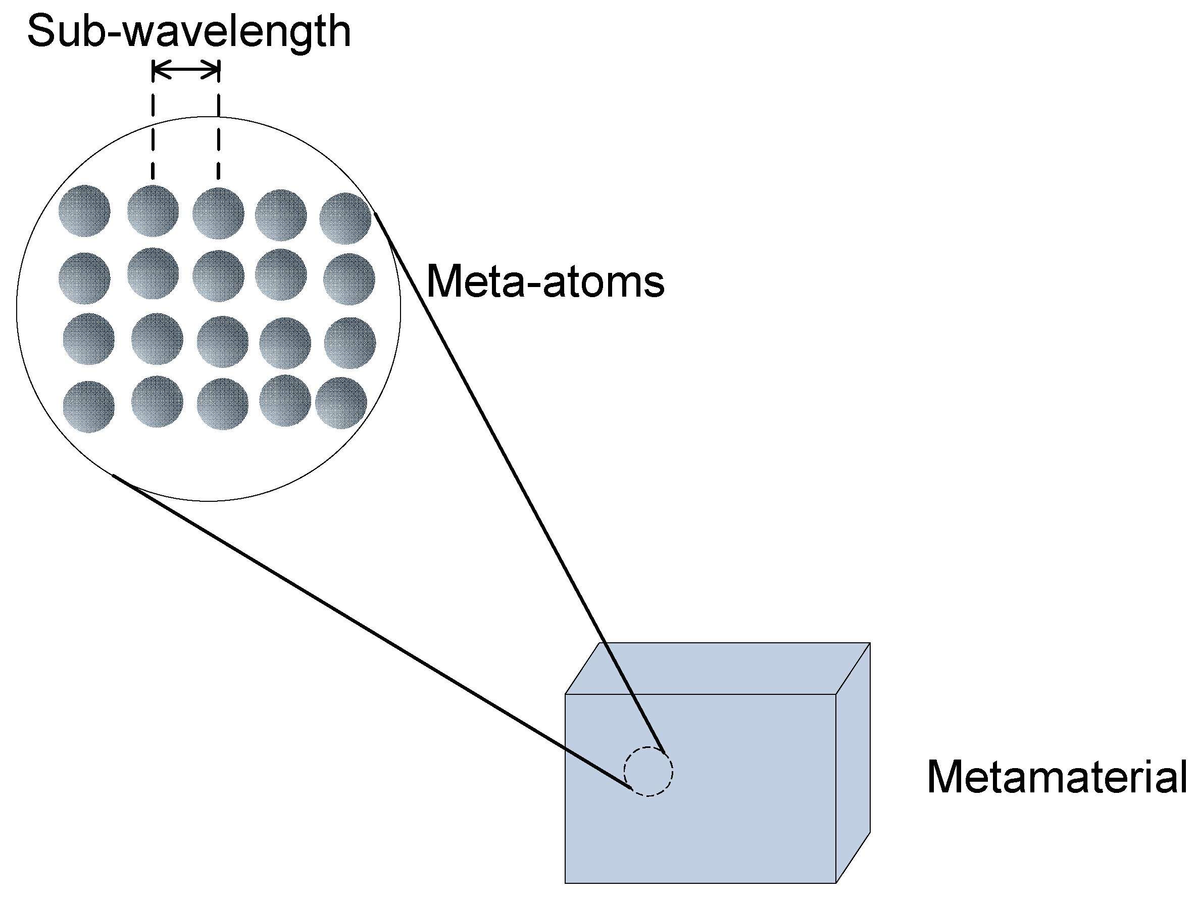
Metasurfaces are the 2D counterparts of metamaterials, which consist of sub-wavelength metallic or dielectric particles that are used to control or modify various parameters, such as amplitude, phase, and polarization [15,16,17]. In recent years, scientists have been interested in the use of artificial materials, which are envisaged to generate significant benefits and introduces various applications. Metamaterials are among these artificial materials, as they are composed of closely spaced sub-wavelength meta-atoms which resonantly couple to both the electric or magnetic components of the incident electromagnetic fields, thereby exhibiting properties that are not found in nature [18,19,20]. By modifying their permittivity and permeability values, metamaterials can control the propagation of a wave, but they still rely on the propagation phenomena to manipulate electromagnetic (EM) waves [21]. In addition, their 3D nature makes them challenging to fabricate and also results in relatively bulky structures as they manipulate a wave over an extremely thin layer [19,22]. Moreover, the planar structure of metasurfaces facilitates the easy fabrication and highly cost-effective fabrication process when compared to the creation of complex 3D metamaterials. Some of the shortfalls brought on by metamaterials can be addressed by the metasurface, which are less bulky. As compared to metamaterials, metasurfaces are considered to be 2D structures instead of 3D structures. As a result, these metasurface structures are used for a variety of applications, including controllable "smart" surfaces, miniaturized cavity resonators, novel wave-guiding structures, compact and wide-angle absorbers and impedance-matching surfaces.
Metamaterials and Metasurface Structures
In recent years, scientists have embarked on research regarding the use of artificial materials, which generate significant benefits and introduces various applications. Metamaterials are among these artificial materials, as they are composed of closely spaced sub-wavelength meta-atoms, which resonantly couple to both the electric or magnetic components of the incident electromagnetic fields, thereby exhibiting properties that are not found in nature, as shown in Figure 1 [18,19,20].
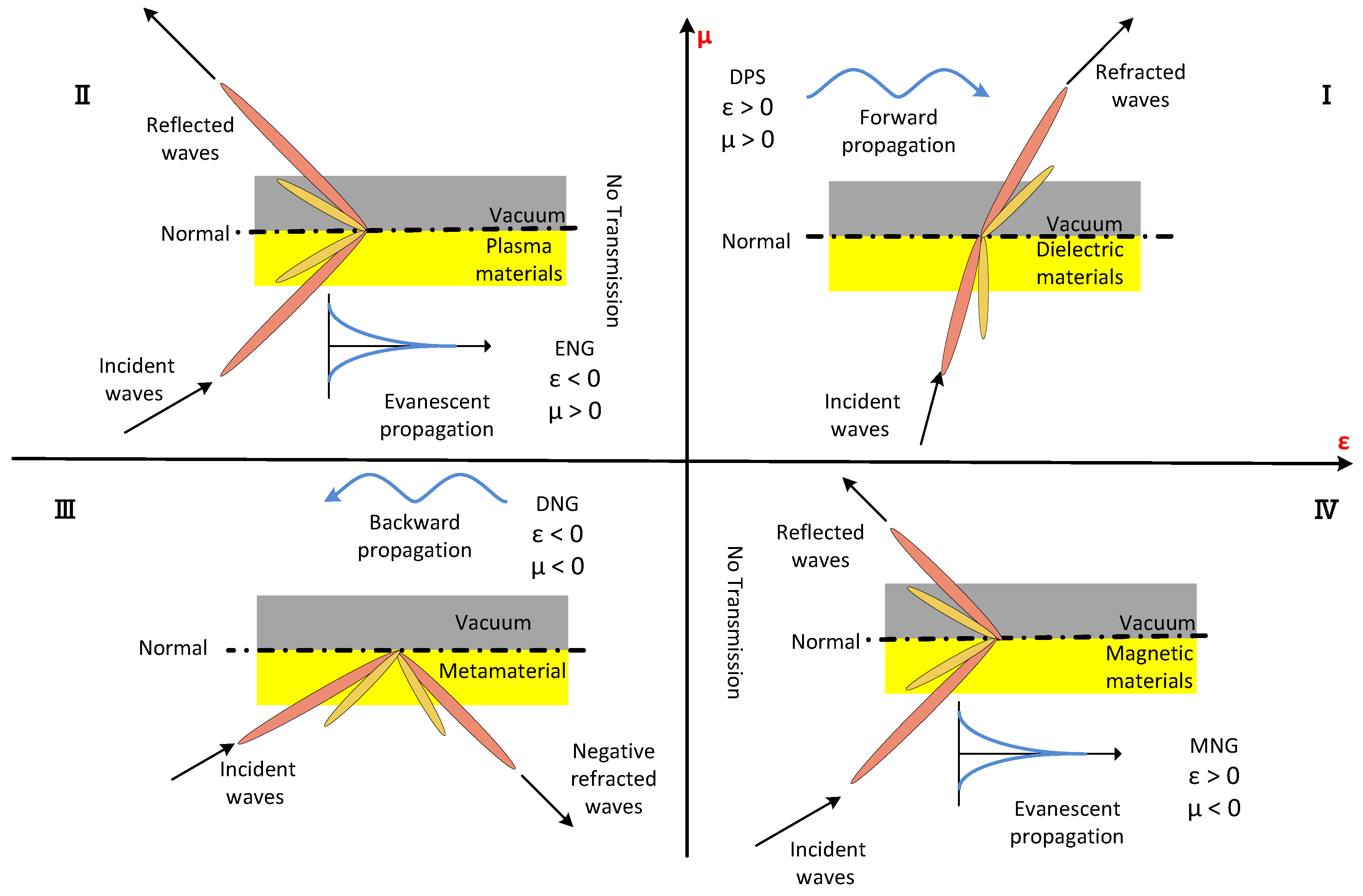
Consequently, they have physical properties that are largely determined by their structures rather than their individual attributes. Furthermore, different structures influence the categorization of metamaterials according to their electrical permittivity and magnetic permeability, denoted as and () values, respectively [23]. The authors in [24] made it possible to classify these materials in four different classes, as shown in Figure 2.
The first quadrant from Figure 2 is characterized by the existence of both positive and values. Such materials are known as double positive (DPS). These can be found in nature, for example, in dielectric materials where EM waves propagate. The second quadrant consists of materials that are represented by a plasma and are known as epsilon negative medium (ENG) due to < 0 and > 0 values [25]. The third quadrant is of interest, being that both and values of materials are negative and not found in nature, hence why it is called the double negative medium (DNG). Furthermore when plane waves propagate in metamaterials, the electric field, magnetic field, and wave vector adopt the left-hand rule, hence why they are referred to as left-handed materials [26]. The fourth quadrant is called the mu negative medium (MNG), represented by magnetic materials as it entails positive and negative values. From Figure 2, one can see that the majority of waves propagate through two mediums namely; region I and III.
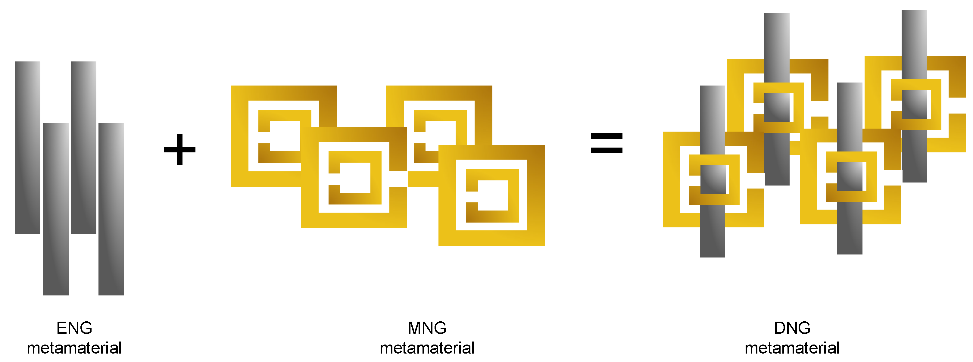
Presently, most metamaterials are being designed with two basic types of structures: dense arrays of thin wires (the electric dipoles) and arrays of split-ring resonators (SRRs) (the magnetic loops), which are metallic rings etched onto a dielectric substrate in a concentric pattern [27,28]. According to the authors in [29], SRRs are considered as unit cells of DNG metamaterials. In order to attain DNG mediums, ENG and MNG mediums are combined, as shown in Figure 3. This paper will focus on the third quadrant as they give metamaterials the property/ability to control EM waves.
Metasurface unit cells consist of SRRs, which comprise negative effective permeability at frequencies closer to the resonant frequency and are used to make left handed media with negative refractive index [30]. The geometric parameters of the ring resonator and the resonant frequency are dependent on each other [28]. Over the course of development of metasurfaces, the limitations of fixed response metasurfaces in realistic applications, i.e., limited working bandwidths and fixed wave manipulation capabilities, were realized [31]. As a result, many efforts have been devoted to developing reconfigurable metasurfaces (RMS) that can actively control EM waves with external tunings. RMSs involve adding tunability to each unit cell which allows for more capabilities of metasurface applications. In the context of wireless communication, they are mostly considered passive reflecting devices used to shape the propagation environment [32,33,34,35]. As an alternative, recent studies presented an application of RMSs as massive MIMO active reconfigurable antennas with developed analog signal processing capabilities for next generation transceivers [8,14,36]. RMS antennas achieve higher power efficiency as they eliminate the need for active phase shifters. Furthermore, the RMS antenna elements can be packed into a relatively small space and be operated over a wide range of frequencies, making them more flexible in size than conventional antennas [14].
2. Related Works
Several researchers have reported various RMSs in the last decade [22,37,38,39,40,41,42,43,44,45]. Works in [42] proposed a reconfigurable metasurface antenna based on a PIN diode for beam switching applications. The authors proposed a metasurface consisting of periodic double-SRR, whose fundamental resonant frequency could easily be controlled by their respective dimensions. Based on their simulations and experiments, the proposed metasurface antenna had good impedance matching and moderate gain performance of about 6 dBi across the band of interest. In Ref. [46], the authors presented a dynamically reconfigurable holographic metasurface antenna for applications in near-field beam focusing. Through the use of the proposed metasurface antenna, the authors achieved beam-focusing without requiring phase shifters and power amplifiers. This concluded that the proposed metasurface antenna was suitable for applications that require dynamic reconfigurability, such as imaging and wireless power transfer.
Works in Refs. [43,47] presented a reconfigurable metasurface antenna that manipulated scattering fields by liquid metal. The reflected element phase responses underwent distinct phase differences when the metal shape of the metasurface element changed along the polarization direction. It was concluded that the liquid-metal metasurface antenna presented had less system complexity, lower cost, and much lower power consumption. In Ref. [48], a frequency reconfigurable dielectric resonator antenna using metasurfaces was proposed. The attained bandwidth and gain of the proposed metasurface antenna was 1.1 GHz and 7.8 dBi, respectively. The authors in Ref. [49] designed and evaluated rectangular and circular SRR structures to create a metamaterial superstructure with improved antenna characteristics such as gain, bandwidth, and radiation pattern. However, from literature, there has not been an explicit method on how to calculate each geometrical parameter of SRRs.
Contribution
This paper proposes a unified simple design procedure used in antennas to calculate the geometrical parameters of SRRs, which are used in metasurface unit cells. The proposed unit cell is further used to design a PIN diode based elements reconfigurable metasurface antenna for the realization of dual band operation at mmWave frequencies. The main contributions of this chapter are summarized as follows:
- Firstly, a demonstration of a step-by-step procedure on how to achieve SRR geometrical parameters at dual frequency of operation is provided;
- Secondly, the proposed unit cell was used to design a 16 element frequency RMS;
- Finally, the characteristics of the proposed frequency RMS were analyzed and compared with previous works.
3. Design Procedure
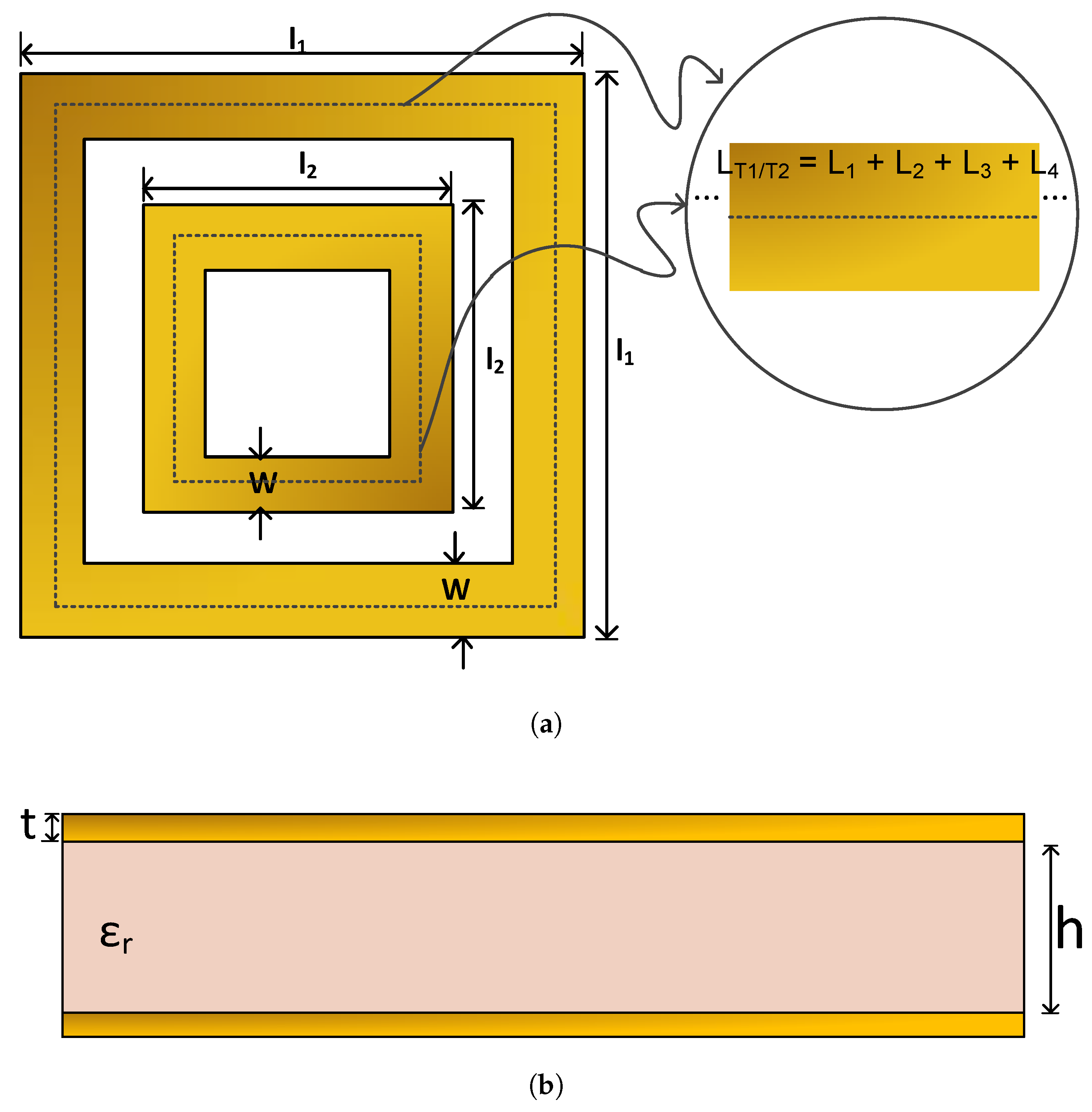
According to [50], ring resonators are described as two identical half guided wavelength , which establish standing waves in parallel. Figure 4 depicts a schematic view of the dual band square SRR structure.
Since and in Figure 4 represents the total path transversed by EM waves in the internal and external ring respectively, and the fundamental mode length is represented as,
The guided wavelength at resonant frequency is represented by the following equation [50]
therefore, the internal and external ring guided wavelengths & respectively are given as
where resonance frequencies of the internal and external rings are defined by and respectively. The effective dielectric constant is calculated as [51]
where represents the dielectric constant. To attain the internal and external ring average length at any specified resonant frequency, Equation (2) is substituted into Equation (1) to give [50]
Furthermore, since the resonators exhibit the same standing waves at the fundamental modes, Equation (5) is used for both one-port and two-port resonators [50].
From the specified substrate information, the dielectric constant and height h are used to calculate the width W of the ring resonator. For a given characteristic impedance , the width was represented as;
where
From Equation (5), the internal and external side lengths and of each ring of the SRR can be calculated by,
4. Simulation Processes
With the foregoing mathematical analysis, a practical square split ring resonator was designed using CST MWS software. The MWS is based on solving Maxwell’s equations in differential form in the time domain explicitly [54]. Additionally, it is highly desirable to use time domain simulations methods for high frequency electromagnetic applications, especially when broadband results are desired [55]. In this work, a square SRR resonating at 28 GHz and 40 GHz was constructed on an RT5880 substrate with a height of 0.5 mm, as depicted in Figure 4. The metallic layer used was the lossy annealed copper. The desired dimensions were obtained by using design equations discussed in Section 3 and a summary of a step-by-step design procedure is shown in Table 1.
Following the use of the design procedure, in order to optimize the calculated parameters of the unit cell of the metasurface, the CST optimizer tool from the software was used. Table 2 depicts the dimensions of the unit cell before and after optimization.
In order to perform simulation in CST MWS, the boundary conditions have to be defined. For the software to generate EM waves, the boundary conditions of the , and were defined as a perfect electric conductor, perfect magnetic conductor and open respectively. This means that for and the magnetic fluxes are set to zero, for and electric fluxes are set to zero and with and waves can pass with minimal reflections. The proposed structure was excited by defining two wave ports which were normal to the . The time domain solver which comprises of finite difference time domain (FDTD) was used to calculate transmission of energy between excitation sources and obtain broadband frequency behaviour of the simulated structure.
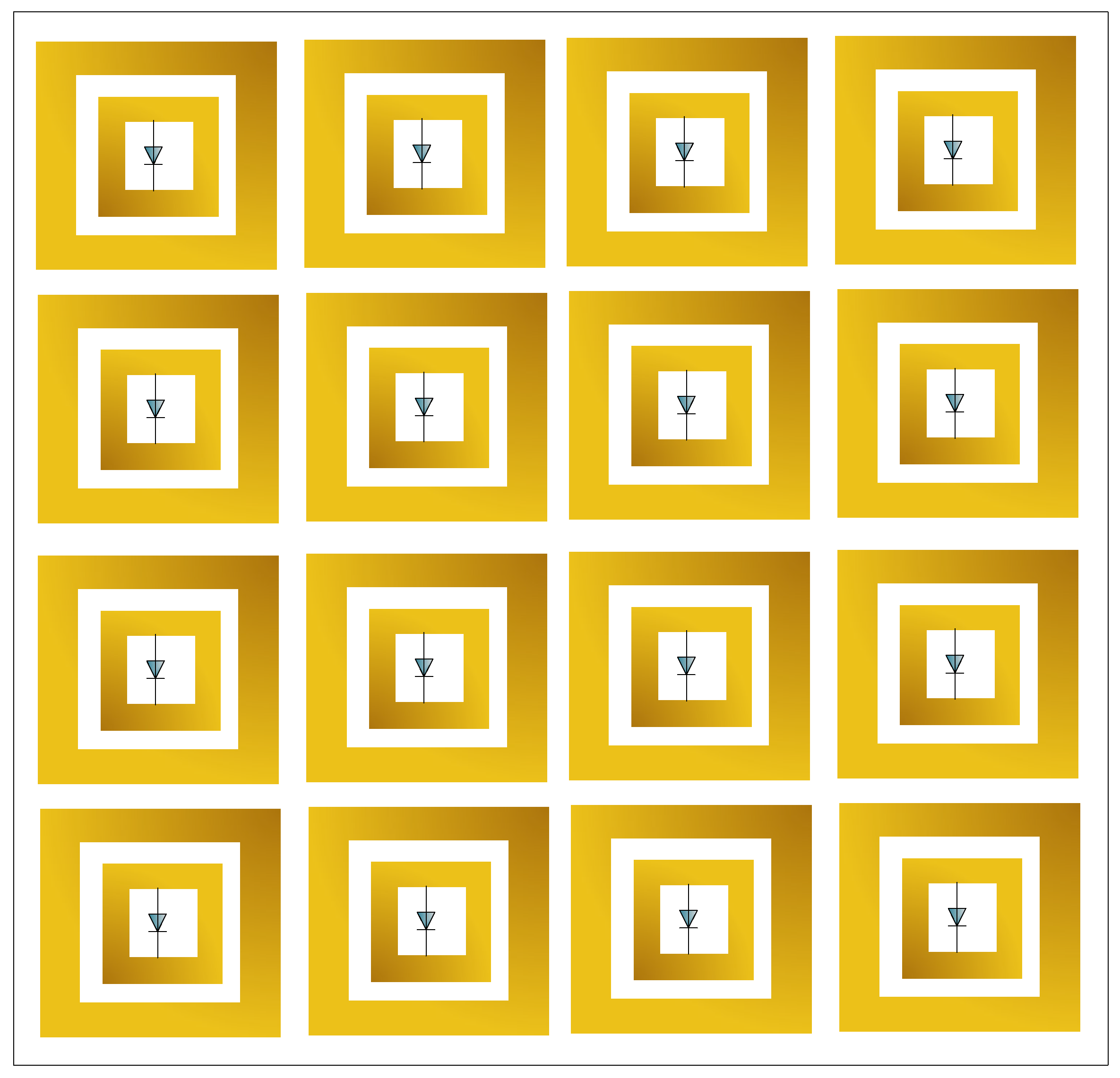
To achieve reconfigurability, the designed unit cell was made into a 4 × 4 element integrated with diodes, as shown in Figure 5. Similar to authors in [56], each unit cell of the metasurface was connected to a diode.
In an array of SRR unit cells, there is an increased magnetic response [57], due to an alternating magnetic field perpendicular to the SRR plane. The SRR behaves as a simple LC resonator, with capacitance resulting from the separation of charges across the split and inductance being the result of currents circulating in the ring, exhibiting a resonant response at a specific frequency [58,59]. The resonant circular currents give rise to a resonant magnetic dipole moment, which is responsible for the negative permeability part of negative refraction [59]. Furthermore, the electromagnetic response can also be influenced by the mutual coupling between SRR unit cells [60]. Mutual coupling is when antenna elements that are near each other, either transmitting or receiving, will leak some of the energy that is intended for one to the other [51]. The strength of coupling between SRR unit cells is dependent on the separation between them and the orientation of each unit cell [59]. In this proposed work, there is high potential existence of mutual coupling since the unit cells are closely spaced by 5.18 mm. In addition, superdirectivity could be achieved due to the proximity of the unit cells from each other [51,61]. However, the focus of this paper is to design a frequency reconfigurable metasurface antenna without mitigating the mutual coupling effect between the unit cells. Mutual coupling effects and superdirectivity will be investigated in future works.
5. Results and Analysis
As a result of the computations from CST MWS, optimized dimensions, return loss curves, reflection phase, gain, directivity, effective permittivity, and permeability of the proposed frequency RMS were analyzed in this section.
5.1. Reflection Coefficient
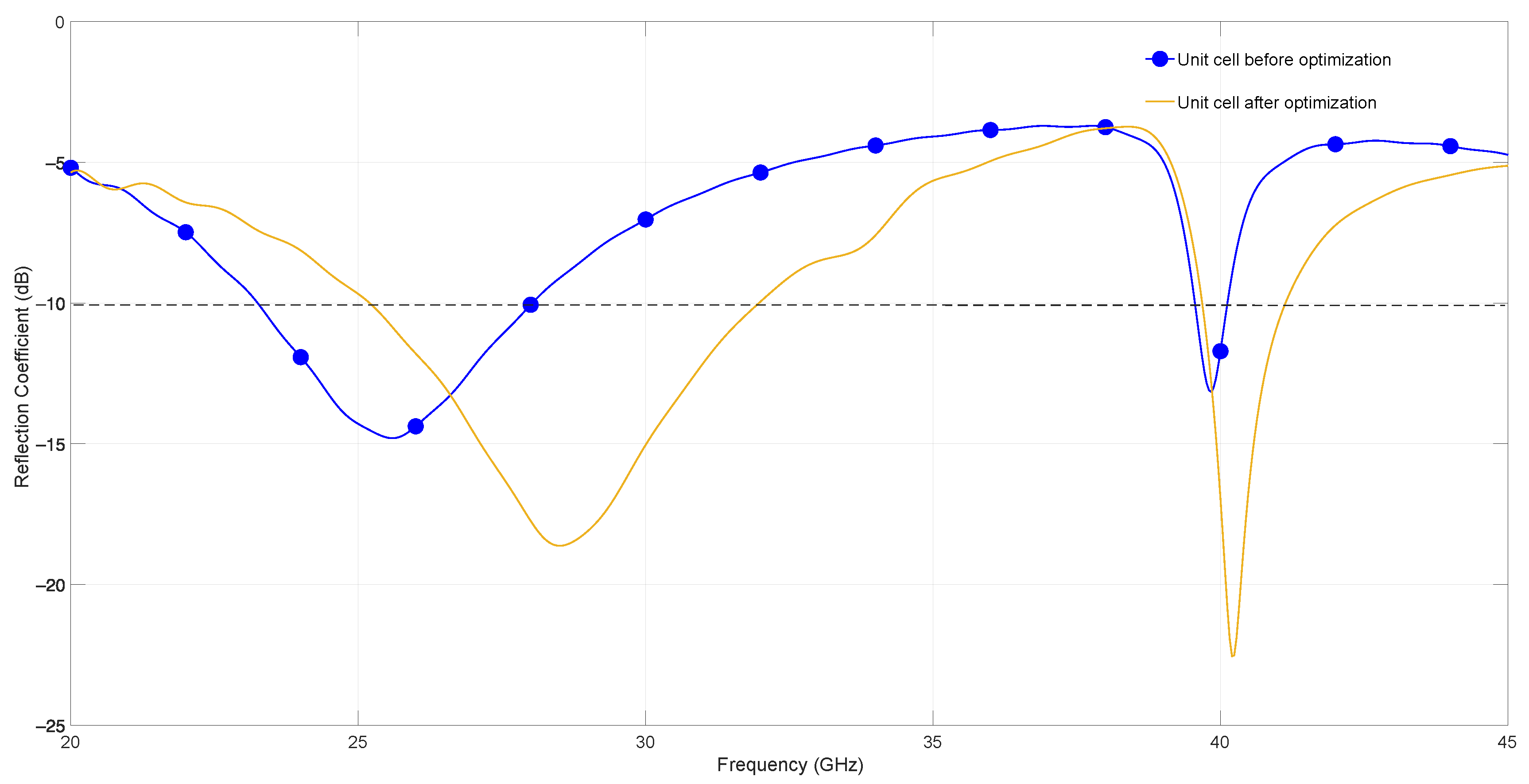
For resonant frequencies of 28 GHz and 40 GHz, a reflection coefficient/return loss graph that shows the ratio of the amplitude of the reflected wave to the incident wave was simulated, yielding the results shown in Figure 6. As seen from the figure, before optimization, the unit cell resonated at 25.6 GHz and 39.85 GHz with a magnitude of −14.80 dB and −13.11 dB, respectively. With the use of the CST optimizer, the unit cell resonated at 28.3 GHz and 40.3 GHz with a reflection coefficient of −18.57 dB and −22.0 dB, respectively. The bandwidth of the unit cell before optimization was 4.65 GHz and 0.67 GHz and, after optimization, as depicted at the −10 dB mark in Figure 6, it was 6.8 GHz and 1.50 GHz. When the unit cell was optimized, it resonated at a frequency closer to the desired operating frequencies (i.e., 28 GHz and 40 GHz) with less reflection than before. As a result, the optimized return loss results of the unit cell were used to analyze a 4 × 4 frequency RMS antenna structure shown in Figure 5. The student version simulation software was not licensed for hundreds of elements, therefore an array characterized by 16 elements was chosen.
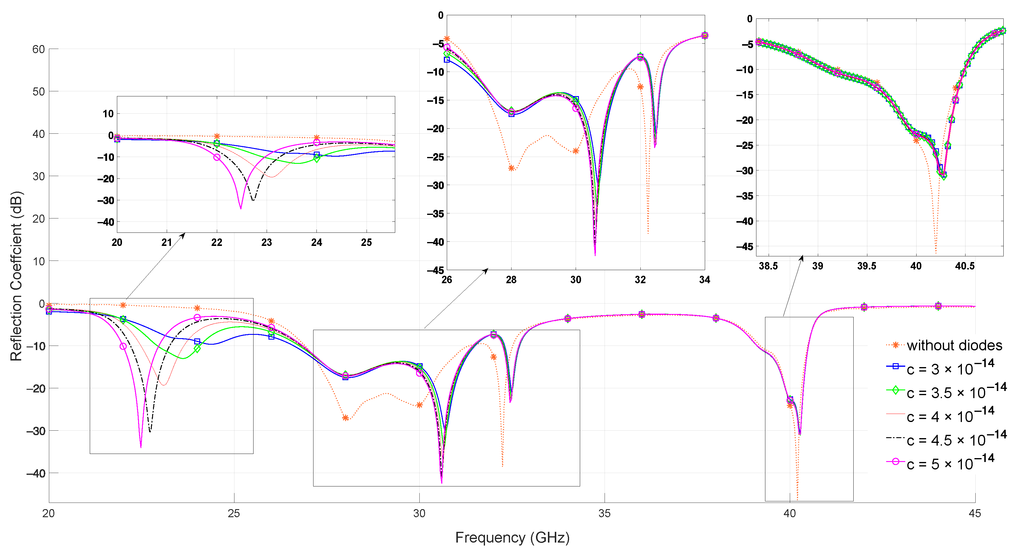
Figure 7 depicts the return loss results for a 4 × 4 metasurface antenna with and without adding PIN diodes from the lumped elements section in CST MWS, which enable frequency reconfigurability. The results are further numerically summarized in Table 3. It was observed that when diodes were added, the resonating frequency decreased as the capacitance increased. From the table, the bandwidth of the 16 element metasurface antenna without diodes was relatively the same as when they were added. Furthermore, it can be observed from this table and figure that the proposed metasurface antenna array was capable of frequency reconfiguration.
5.2. Reflection Phase
Figure 8 shows the reflection phase for the proposed 16 elements metasurface antenna with and without PIN diodes. As observed from the figure, there was a phase difference of 21.8° and 4.3° at 28 GHz and 40 GHz (designed operating frequencies), respectively, as diode capacitance was increased. Additionally, before adding the diodes, there was a phase shift of 360° at 26.08 GHz and at 26.68 GHz when the diodes were added for all capacitance values. The same phase shift was also observed at 22.7 GHz for when capacitance was 0.05 pF.
5.3. Gain and Directivity
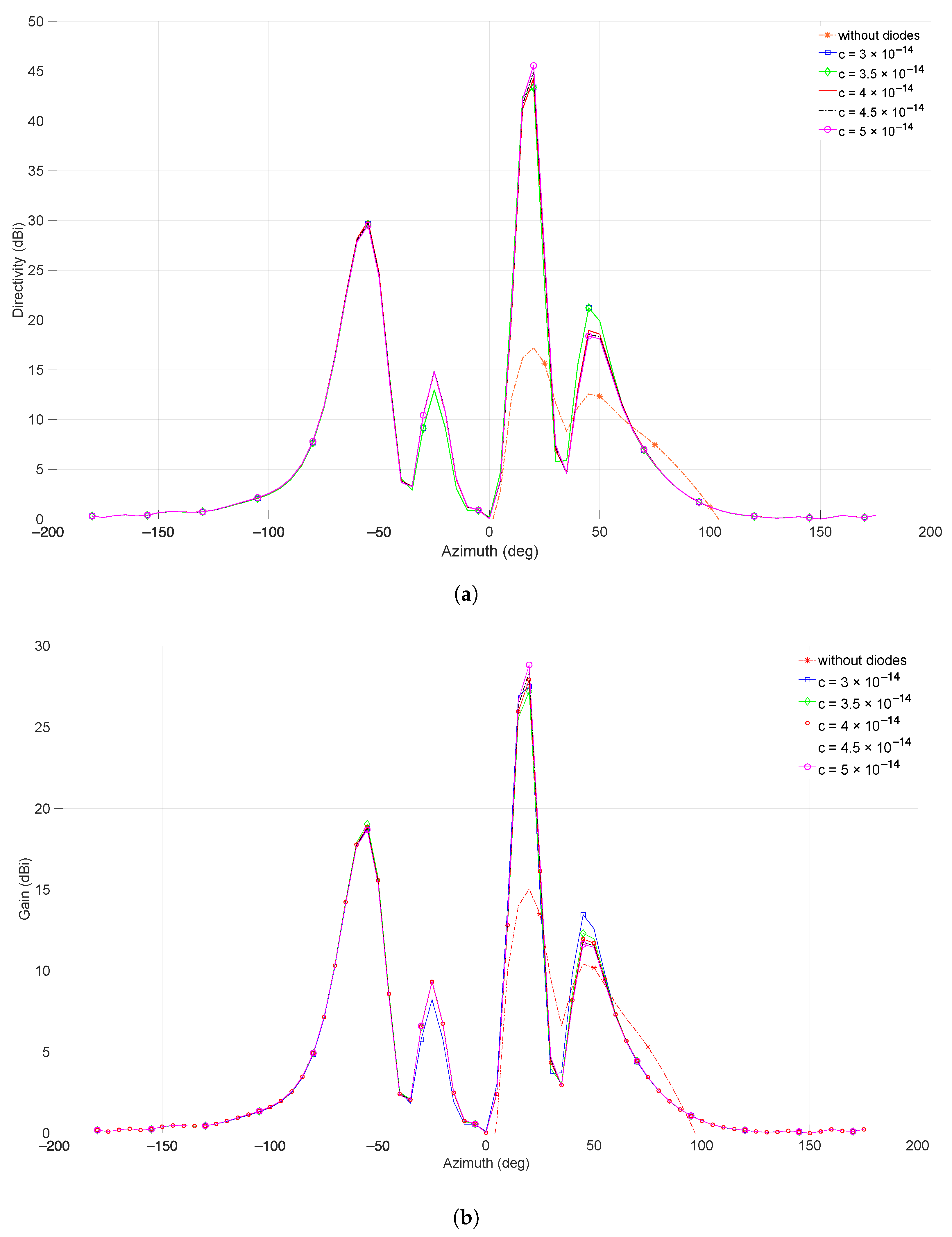
According to [51], directivity is a property of RF systems which determines how concentrated the radiation emitted is in one direction. It is a factor affecting the gain in these systems. The gain describes how well the proposed structure converts input power into radio waves, which travel in a particular direction [51]. Despite the fact that the gain of the metasurface antenna is closely related to its directivity, it is also a measure of its efficiency and directional capabilities [51]. The simulated results in Figure 9 depict the directivity and gain results before and after the lumped elements were installed on the 16 element metasurface antenna. Table 4 shows a numerical summary of the figure.
From Table 4, the gain and directivity of the reconfigurable 16 elements metasurface antenna increased when diodes were added. This is due to the decreased angular beamwidth, which led to a narrower beam, resulting in higher directivity and gain [64]. However, since the proposed SRR unit cells are made of copper, when the current is applied, it moves towards the surface of the conducting material, decreasing its effective cross section. This tendency is known as the skin effect and it is the reason attenuation increases with frequency because of high loss resistance. This can result in decreased gain and should be taken into consideration during the design and implementation processes. Furthermore, the directivity and gain were used to compute the radiation efficiency using Equation (15) [51,65]
Since PIN diodes are connected to metallic strips of the metasurface antenna array, loss can occur due to the dissipation of power, which affects the radiation efficiency. It was observed from Table 4 that the radiation efficiency of the metasurface antenna array decreased when diodes were added.
According to [66], the resistance of the diode does not affect the operating frequency. As a result, capacitance and inductance of the switches have no effect on the gain nor directivity. From Table 4, the directivity, gain, and radiation efficiency with varying capacitances was relatively the same.
5.4. Effective Permittivity, and Permeability
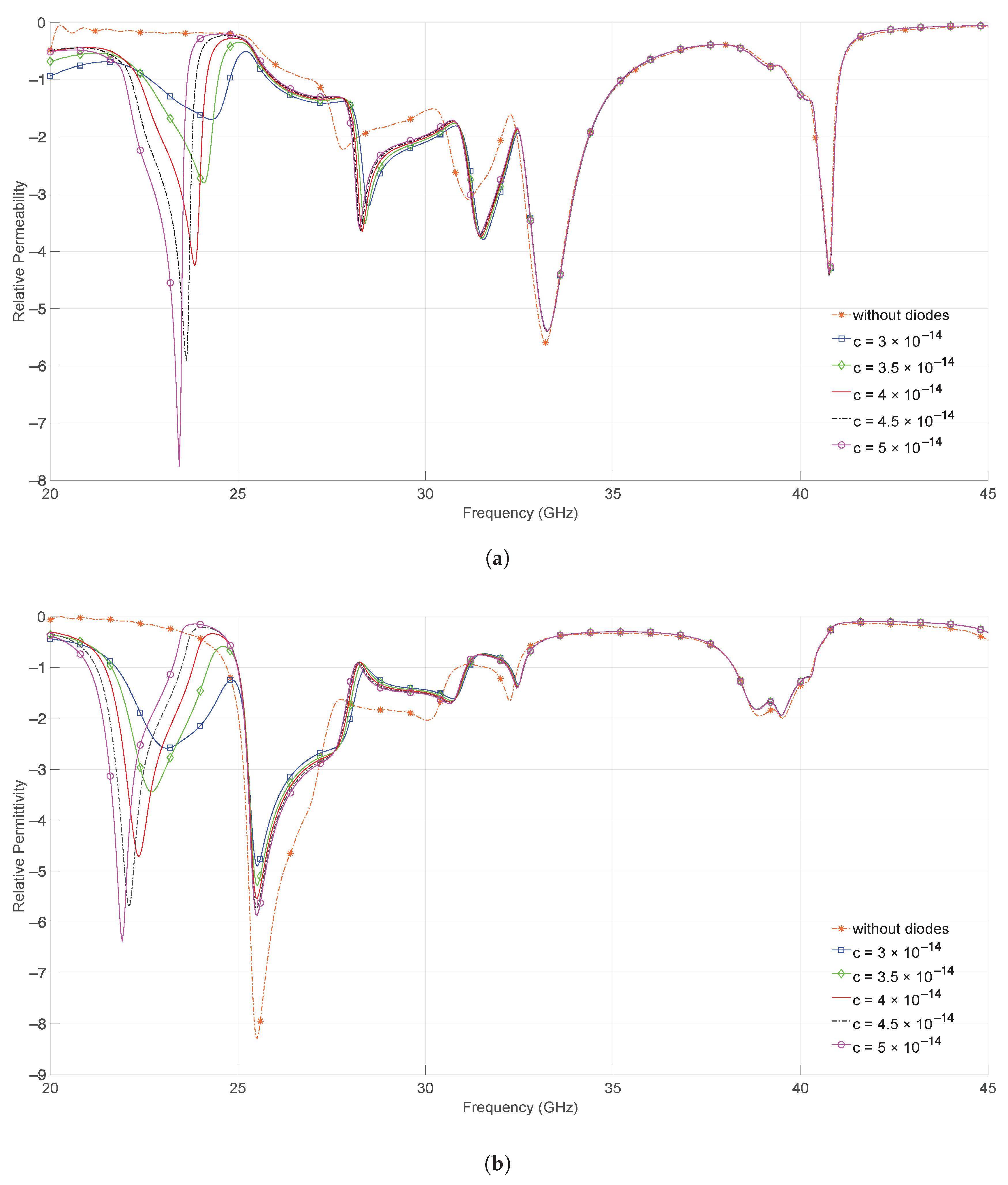
From Figure 10, the 16 elements metasurface antenna permittivity and permeability before and after adding diodes were all negative. These results were obtained from the CST MWS software, which used a method by [67] to retrieve the effective constitutive parameters (permittivity and permeability) of a slab of metamaterial from the measurement of scattering parameters. Frequency reconfigurability can also be observed from this figure. Since and were negative at all resonating frequencies, as shown in Figure 10a,b, this indicates that both the designed 4 × 4 metasurface antenna structure and its frequency reconfigurable structure were double negative metasurfaces, which exhibits the phenomenal ability of negative refraction. Furthermore, Equations (10) and (11) can be used to verify whether and are negative.
5.5. Comparison with Previous Work
The performance comparisons between the proposed 16 elements frequency RMS antenna and other designs are given in Table 5.
It can be observed from this table that previous work did not specify how the dimensions of the metasurface were calculated.
6. Conclusions
This work proposed a step-by-step design method for a frequency reconfigurable metasurface antenna with the ability to adjust its operating frequency by utilizing semiconductor diodes such as PIN diodes. A simplified unified demonstration on how a metasurface antenna unit cell was designed theoretically from split ring resonators in order to attain its geometrical dimensions at any frequency of resonance was shown. The radiation mechanisms of the 16 element metasurface and RMS antenna were explained in detail via the reflection phase and its magnitude characteristics. It was observed that when diodes were added, the resonating frequency decreased as the capacitance increased. The proposed frequency RMS antenna exhibited a wideband operational bandwidth from 25 to 32 GHz and approximately at 40 GHz. In addition, multiple gain variations from 27.33 dBi to 28.8 dBi were observed across the full operating band at different diode capacitances. It was also observed that the gain and directivity increased when diodes were added due to decreased angular beamwidth. However, radiation efficiency decreased because of the loss that occurred due to the dissipation of power from the added diodes. From the proposed frequency RMS antenna, the gain, directivity, and radiation efficiency did not vary as the frequency of operation changed. The proposed 16 elements structure has proven to be a double negative metasurface, which means that it has the ability to dynamically shape electromagnetic fields. There has been considerable success with reconfigurable metasurface antennas in the microwave regime, but the use of metasurfaces in future communication has enormous potential for further research.
Author Contributions
Methodology, B.K.L.; supervision, M.M. and B.B.; writing—review and editing, P.M. and R.R. All authors have read and agreed to the published version of the manuscript.
Funding
This research was funded by Botswana International University of Science and Technology grant number S00190 and S00378.
Conflicts of Interest
The authors declare no conflict of interest.
References
- Masoudi, M.; Khafagy, M.G.; Conte, A.; El-Amine, A.; Françoise, B.; Nadjahi, C.; Salem, F.E.; Labidi, W.; Süral, A.; Gati, A.; et al. Green Mobile Networks for 5G and Beyond. IEEE Access 2019, 7, 107270–107299. [Google Scholar] [CrossRef]
- Meng, X.; Nekovee, M.; Wu, D. Reconfigurable liquid crystal reflectarray metasurface for THz communications. In Proceedings of the Antennas and Propagation Conference 2019 (APC-2019), Birmingham, UK, 11–12 November 2019; pp. 1–6. [Google Scholar] [CrossRef]
- Yang, P.; Xiao, Y.; Xiao, M.; Li, S. 6G Wireless Communications: Vision and Potential Techniques. IEEE Netw. 2019, 33, 70–75. [Google Scholar] [CrossRef]
- Awan, W.A.; Alibakhshikenari, M.; Limiti, E. Design and Analysis of a Simple Miniaturized Fractal Antenna for 5G Ka-Band Applications. In Proceedings of the 2021 IEEE Asia-Pacific Microwave Conference (APMC), Brisbane, Australia, 28 November–1 December 2021; pp. 22–24. [Google Scholar] [CrossRef]
- Naqvi, S.A.; Awan, W.A.; Alibakhshikenari, M.; Falcone, F.; Limiti, E. Design and Characterization of a Simple and Wideband Antenna for 5G mm-wave Applications. In Proceedings of the 2020 IEEE MTT-S Latin America Microwave Conference (LAMC 2020), Cali, Colombia, 26–28 May 2021; pp. 1–3. [Google Scholar] [CrossRef]
- Rusek, F.; Persson, D.; Lau, B.K.; Larsson, E.G.; Marzetta, T.L.; Edfors, O.; Tufvesson, F. Scaling up MIMO: Opportunities and challenges with very large arrays. IEEE Signal Process. Mag. 2012, 30, 40–60. [Google Scholar] [CrossRef] [Green Version]
- Chataut, R.; Akl, R. Massive MIMO Systems for 5G and beyond Networks—Overview, Recent Trends, Challenges, and Future Research Direction. Sensors 2020, 20, 2753. [Google Scholar] [CrossRef]
- Shlezinger, N.; Dicker, O.; Eldar, Y.C.; Yoo, I.; Imani, M.F.; Smith, D.R. Dynamic Metasurface Antennas for Uplink Massive MIMO Systems. IEEE Trans. Commun. 2019, 67, 6829–6843. [Google Scholar] [CrossRef] [Green Version]
- Alkhateeb, A.; Mo, J.; González-Prelcic, N.; Heath, R. MIMO precoding and combining solutions for millimeter-wave systems. IEEE Commun. Soc. Mag. 2014, 52, 122–131. [Google Scholar] [CrossRef]
- Mo, J.; Alkhateeb, A.; Abu-Surra, S.; Heath, R.W. Hybrid Architectures with Few-Bit ADC Receivers: Achievable Rates and Energy-Rate Tradeoffs. IEEE Trans. Wirel. Commun. 2017, 16, 2274–2287. [Google Scholar] [CrossRef]
- Sleasman, T.; Boyarsky, M.; Pulido-Mancera, L.; Fromenteze, T.; Imani, M.F.; Reynolds, M.S.; Smith, D.R. Experimental Synthetic Aperture Radar with Dynamic Metasurfaces. IEEE Trans. Antennas Propag. 2017, 65, 6864–6877. [Google Scholar] [CrossRef] [Green Version]
- Yang, W.; Chen, S.; Che, W.; Xue, Q.; Meng, Q. Compact High-Gain Metasurface Antenna Arrays Based on Higher-Mode SIW Cavities. IEEE Trans. Antennas Propag. 2018, 66, 4918–4923. [Google Scholar] [CrossRef]
- Smith, D.R.; Yurduseven, O.; Mancera, L.P.; Bowen, P.; Kundtz, N.B. Analysis of a Waveguide-Fed Metasurface Antenna. Phys. Rev. Appl. 2017, 8, 054048. [Google Scholar] [CrossRef] [Green Version]
- Yoo, I.; Imani, M.F.; Sleasman, T.; Pfister, H.D.; Smith, D.R. Enhancing Capacity of Spatial Multiplexing Systems Using Reconfigurable Cavity-Backed Metasurface Antennas in Clustered MIMO Channels. IEEE Trans. Commun. 2019, 67, 1070–1084. [Google Scholar] [CrossRef]
- Rotshild, D.; Rahamim, E.; Abramovich, A. Innovative Reconfigurable Metasurface 2-D Beam-Steerable Reflector for 5G Wireless Communication. Electronics 2020, 9, 1191. [Google Scholar] [CrossRef]
- Achouri, K.; Salem, M.A.; Caloz, C. General Metasurface Synthesis Based on Susceptibility Tensors. IEEE Trans. Antennas Propag. 2015, 63, 2977–2991. [Google Scholar] [CrossRef] [Green Version]
- Vahabzadeh, Y.; Chamanara, N.; Achouri, K.; Caloz, C. Computational analysis of metasurfaces. IEEE J. Multiscale Multiphys. Comput. Tech. 2018, 3, 37–49. [Google Scholar] [CrossRef] [Green Version]
- Chen, H.T.; Taylor, A.J.; Yu, N. A review of metasurfaces: Physics and applications. Rep. Prog. Phys. 2016, 79, 76401. [Google Scholar] [CrossRef] [Green Version]
- Bukhari, S.S.; Vardaxoglou, J.; Whittow, W. A Metasurfaces Review: Definitions and Applications. Appl. Sci. 2019, 9, 2727. [Google Scholar] [CrossRef] [Green Version]
- Choudhury, P.; El-Nasr, M.A. Waves in resonant metasurfaces. J. Electromagn. Waves Appl. 2020, 34, 1309–1313. [Google Scholar] [CrossRef]
- Yu, N.; Capasso, F. Flat optics with designer metasurfaces. Nat. Mater. 2014, 13, 139–150. [Google Scholar] [CrossRef]
- He, Q.; Sun, S.; Zhou, L. Tunable/Reconfigurable Metasurfaces: Physics and Applications. Research 2019, 2019, 1849272. [Google Scholar] [CrossRef] [Green Version]
- Zheludev, N.; Kivshar, Y. From metamaterials to metadevices. Nat. Mater. 2012, 11, 917–924. [Google Scholar] [CrossRef]
- Veselago, V.G. The Electrodynamicsof substances with simultaneously negative values of ϵ and μ. Usp. Fiz. Nauk 1967, 92, 517. [Google Scholar] [CrossRef]
- Krzysztofik, W.J.; Cao, T.N. Metamaterials in application to improve antenna parameters. Metamater. Metasurf. 2018, 12, 63–85. [Google Scholar]
- Antipov, S.; Liu, W.; Power, J.; Spentzouris, L. Left-Handed Metamaterials Studies and their Application to Accelerator Physics. In Proceedings of the 2005 Particle Accelerator Conference, Knoxville, TN, USA, 16–20 May 2005; pp. 458–460. [Google Scholar] [CrossRef]
- Tong, X.C. Functional Metamaterials and Metadevices; Springer: Cham, Switzerland, 2018. [Google Scholar]
- Alici, K.B.; Ozbay, E. Radiation properties of a split ring resonator and monopole composite. Phys. Status Solidi B Basic Solid State Phys. 2007, 244, 1192–1196. [Google Scholar] [CrossRef]
- Sliusar, I.; Slyusar, V.; Utkin, Y.; Kopishynska, O. Parametric synthesis of 3D structure of SRR element of the metamaterial. In Proceedings of the 2020 IEEE International Conference on Problems of Infocommunications. Science and Technology (PIC S&T), Kharkiv, Ukraine, 6–9 October 2020; pp. 577–582. [Google Scholar]
- Aydin, K.; Guven, K.; Kafesaki, M.; Soukoulis, C.; Ozbay, E. Experimental observation of true left-handed transmission peak in metamaterials. Opt. Lett. 2004, 29, 2623–2625. [Google Scholar] [CrossRef] [Green Version]
- Shaltout, A.; Kinsey, N.; Kim, J.; Chandrasekar, R.; Ndukaife, J.; Boltasseva, A.; Shalaev, V. Development of Optical Metasurfaces: Emerging Concepts and New Materials. Proc. IEEE 2016, 104, 1–18. [Google Scholar] [CrossRef]
- Basar, E. Transmission through Large Intelligent Surfaces: A New Frontier in Wireless Communications. In Proceedings of the 2019 European Conference on Networks and Communications (EuCNC), Valencia, Spain, 18–21 June 2019; pp. 112–117. [Google Scholar] [CrossRef] [Green Version]
- Lv, L.; Wu, Q.; Li, Z.; Al-Dhahir, N.; Chen, J. Secure Two-Way Communications via Intelligent Reflecting Surfaces. IEEE Commun. Lett. 2021, 25, 744–748. [Google Scholar] [CrossRef]
- Wu, Q.; Zhang, R. Intelligent Reflecting Surface Enhanced Wireless Network via Joint Active and Passive Beamforming. IEEE Trans. Wirel. Commun. 2019, 18, 5394–5409. [Google Scholar] [CrossRef] [Green Version]
- Feng, K.; Li, X.; Han, Y.; Jin, S.; Chen, Y. Physical Layer Security Enhancement Exploiting Intelligent Reflecting Surface. IEEE Commun. Lett. 2021, 25, 734–738. [Google Scholar] [CrossRef]
- Shlezinger, N.; Alexandropoulos, G.C.; Imani, M.F.; Eldar, Y.C.; Smith, D.R. Dynamic metasurface antennas for 6G extreme massive MIMO communications. IEEE Wirel. Commun. 2021, 28, 106–113. [Google Scholar] [CrossRef]
- Guanxing, Z.; Liu, Z.; Deng, W.; Zhu, W. Reconfigurable metasurfaces with mechanical actuations: Towards flexible and tunable photonic devices. J. Opt. 2020, 23, 013001. [Google Scholar] [CrossRef]
- Tang, W.; Dai, J.Y.; Chen, M.; Li, X.; Cheng, Q.; Jin, S.; Wong, K.K.; Cui, T.J. Programmable metasurface-based RF chain-free 8PSK wireless transmitter. Electron. Lett. 2019, 55, 417–420. [Google Scholar] [CrossRef] [Green Version]
- Tsilipakos, O.; Tasolamprou, A.; Pitilakis, A.; Liu, F.; Wang, X.; Mirmoosa, M.; Tzarouchis, D.; Abadal, S.; Taghvaee, H.; Liaskos, C.; et al. Toward intelligent metasurfaces: The progress from globally tunable metasurfaces to software-defined metasurfaces with an embedded network of controllers. Adv. Opt. Mater. 2020, 8, 2000783. [Google Scholar] [CrossRef]
- Liu, F.; Tsilipakos, O.; Pitilakis, A.; Tasolamprou, A.; Mirmoosa, M.; Kantartzis, N.; Kwon, D.; Kafesaki, M.; Soukoulis, C.; Tretyakov, S. Intelligent Metasurfaces with Continuously Tunable Local Surface Impedance for Multiple Reconfigurable Functions. Phys. Rev. Appl. 2019, 11, 044024. [Google Scholar] [CrossRef] [Green Version]
- Huang, C.; Zhang, C.; Yang, J.; Sun, B.; Zhao, B.; Luo, X. Reconfigurable Metasurface for Multifunctional Control of Electromagnetic Waves. Adv. Opt. Mater. 2017, 5, 1700485. [Google Scholar] [CrossRef]
- Chaimool, S.; Hongnara, T.; Rakluea, C.; Akkaraekthalin, P.; Zhao, Y. Design of a PIN Diode-Based Reconfigurable Metasurface Antenna for Beam Switching Applications. Int. J. Antennas Propag. 2019, 2019, 7216324. [Google Scholar] [CrossRef] [Green Version]
- Qian, T. Reconfigurable Metasurface Antenna Based on the Liquid Metal for Flexible Scattering Fields Manipulation. Micromachines 2021, 12, 243. [Google Scholar] [CrossRef]
- Li, W.; Wang, Y.M.; Hei, Y.; Li, B.; Shi, X. A Compact Low-Profile Reconfigurable Metasurface Antenna with Polarization and Pattern Diversities. IEEE Antennas Wirel. Propag. Lett. 2021, 20, 1170–1174. [Google Scholar] [CrossRef]
- Nemati, A.; Wang, Q.; Hong, M.; Teng, J. Tunable and reconfigurable metasurfaces and metadevices. Opto-Electron. Adv. 2018, 1, 180009. [Google Scholar] [CrossRef] [Green Version]
- Yurduseven, O.; Smith, D.R.; Fromenteze, T. Design of a Reconfigurable Metasurface Antenna for Dynamic Near-Field Focusing. In Proceedings of the 2018 IEEE International Symposium on Antennas and Propagation USNC/URSI National Radio Science Meeting, Boston, MA, USA, 8–13 July 2018; pp. 1707–1708. [Google Scholar] [CrossRef]
- Chen, L.; Ruan, Y.; Cui, H.Y. Liquid metal metasurface for flexible beam-steering. Opt. Express 2019, 27, 23282–23292. [Google Scholar] [CrossRef]
- Abdalrazik, A.; Abdel-Rahman, A.B.; Allam, A.; Abo-Zahhad, M.; Yoshitomi, K.; Pokharel, R.K. Frequency-reconfigurable dielectric resonator antenna using metasurface. Int. J. Microw. Wirel. Technol. 2021, 1–7. [Google Scholar] [CrossRef]
- Xavier, G.; Serres, A.; Costa, E.; Oliveira, A.; Nobrega, L.; Souza, V. Design and Application of a Metamaterial Superstrate on a Bio-Inspired Antenna for Partial Discharge Detection through Dielectric Windows. Sensors 2019, 19, 4255. [Google Scholar] [CrossRef] [PubMed] [Green Version]
- Chang, K.; Hsieh, L.H. Microwave Ring Circuits and Related Structures; Wiley Online Library: Hoboken, NJ, USA, 2004; Volume 156. [Google Scholar]
- Balanis, C.A. Antenna Theory: Analysis and Design, 4th ed.; Wiley: Hoboken, NJ, USA, 2015; p. 1104. [Google Scholar]
- Kumar, M.S.; Basarkod, P.I. A Study of the Effect of Dielectric Composition on Metamaterial Performance in a Multilayer Environment. In Proceedings of the 2019 International Conference on Data Science and Communication (IconDSC), Bangalore, India, 1–2 March 2019; pp. 1–5. [Google Scholar] [CrossRef]
- Smith, D.R.; Schultz, S.; Marko, P.; Soukoulis, C. Determination of effective permittivity and permeability of metamaterials from reflection and transmission coefficients. Phys. Rev. B 2002, 65, 195104. [Google Scholar] [CrossRef] [Green Version]
- Pujari, P.; Vyras, K.; Sharma, B.K. Design & Simulation of Circular Patch Antenna for Multiband application of X Band Using Varactor Diodes. In Proceedings of the Conference on Advances in Communication and Control Systems (CAC2S 2013), Dehradun, India, 6–8 April 2013; Atlantis Press: Paris, France, April 2013; pp. 140–144. [Google Scholar]
- Barrowes, B.; Prishvin, M.; Jutras, G.; Shubitidze, F. High-Frequency Electromagnetic Induction (HFEMI) Sensor Results from IED Constituent Parts. Remote Sens. 2019, 11, 2355. [Google Scholar] [CrossRef] [Green Version]
- Yang, H.; Cao, X.; Yang, F.; Gao, J.; Xu, S.; Li, M.; Chen, X.; Zhao, Y.; Zheng, Y.; Li, S. A programmable metasurface with dynamic polarization, scattering and focusing control. Sci. Rep. 2016, 6, 35692. [Google Scholar] [CrossRef] [PubMed] [Green Version]
- Feth, N.; König, M.; Husnik, M.; Stannigel, K.; Niegemann, J.; Busch, K.; Wegener, M.; Linden, S. Electromagnetic interaction of split-ring resonators: The role of separation and relative orientation. Opt. Express 2010, 18, 6545–6554. [Google Scholar] [CrossRef] [PubMed] [Green Version]
- Penciu, R.S.; Aydin, K.; Kafesaki, M.; Koschny, T.; Ozbay, E.; Economou, E.N.; Soukoulis, C.M. Multi-gap individual and coupled split-ring resonator structures. Opt. Express 2008, 16, 18131–18144. [Google Scholar] [CrossRef] [PubMed]
- Seetharaman, S.S.; King, C.; Hooper, I.R.; Barnes, W.L. Electromagnetic interactions in a pair of coupled split-ring resonators. Phys. Rev. B 2017, 96, 085426. [Google Scholar] [CrossRef] [Green Version]
- Tatartschuk, E.; Gneiding, N.; Hesmer, F.; Radkovskaya, A.A.; Shamonina, E. Mapping inter-element coupling in metamaterials: Scaling down to infrared. J. Appl. Phys. 2012, 111, 094904. [Google Scholar] [CrossRef] [Green Version]
- Radkovskaya, A.; Kiriushechkina, S.; Vakulenko, A.; Petrov, P.; Solymar, L.; Li, L.; Vallecchi, A.; Stevens, C.; Shamonina, E. Superdirectivity from arrays of strongly coupled meta-atoms. J. Appl. Phys. 2018, 124, 104901. [Google Scholar] [CrossRef] [Green Version]
- Sydoruk, O.; Tatartschuk, E.; Shamonina, E.; Solymar, L. Analytical formulation for the resonant frequency of split rings. J. Appl. Phys. 2009, 105, 014903. [Google Scholar] [CrossRef]
- Ashoor, A.; Gupta, S. Metasurface Reflector with Real-Time Independent Magnitude and Phase Control. arXiv 2020, arXiv:2009.13369. [Google Scholar]
- Poisel, R. Antenna Systems and Electronic Warfare Applications; Artech House: Sydney, Australia, 2012. [Google Scholar]
- Nassar, I.T.; Weller, T.M. An electrically small meandered line antenna with truncated ground plane. In Proceedings of the 2011 IEEE Radio and Wireless Symposium, Phoenix, AZ, USA, 16–19 January 2011; pp. 94–97. [Google Scholar]
- Shirazi, M.; Li, T.; Gong, X. Effects of PIN diode switches on the performance of reconfigurable slot-ring antenna. In Proceedings of the 2015 IEEE 16th Annual Wireless and Microwave Technology Conference (WAMICON), Cocoa Beach, FL, USA, 13–15 April 2015; pp. 1–3. [Google Scholar]
- Chen, X.; Grzegorczyk, T.; Wu, B.I.; Pacheco, J.; Kong, J. Robust method to retrieve the constitutive effective parameters of metamaterials. Phys. Rev. E Stat. Nonlinear Soft Matter Phys. 2004, 70 Pt 2, 016608. [Google Scholar] [CrossRef] [PubMed] [Green Version]
- Vassos, E.; Churm, J.; Powell, J.; Viegas, C.; Alderman, B.; Feresidis, A. Air-bridged Schottky diodes for dynamically tunable millimeter-wave metamaterial phase shifters. Sci. Rep. 2021, 11, 5988. [Google Scholar] [CrossRef] [PubMed]
Figure 1.
From meta-atoms to metamaterials.

Figure 2.
(I–IV) Metamaterial classifications based on permittivity and permeability values.

Figure 3.
Creating DNG metamaterials by combining wires and SRR.

Figure 4.
Proposed metasurface unit cell. (a) Top View; (b) Perspective view.

Figure 5.
A 4 × 4 RMS integrated with PIN diodes.

Figure 6.
Return loss results of metasurface unit cell before and after optimization.

Figure 7.
Return loss simulation results of 16 element metasurface array with and without PIN diodes.
Figure 7.
Return loss simulation results of 16 element metasurface array with and without PIN diodes.

Figure 8.
Reflection phase of the 16 element metasurface array with and without PIN diodes.

Figure 9.
Simulation results of a 16 element metasurface array with and without PIN diodes indicating (a) Directivity (b) Gain.
Figure 9.
Simulation results of a 16 element metasurface array with and without PIN diodes indicating (a) Directivity (b) Gain.

Figure 10.
Retrieved effective constitutive parameters of the simulated results (a) Effective permeability (b) Effective permittivity.
Figure 10.
Retrieved effective constitutive parameters of the simulated results (a) Effective permeability (b) Effective permittivity.


Table 1.
Summary of calculation of dimensions of a metasurface unit cell.
| Step | Equation | Purpose |
|---|---|---|
| 1 | Equation (6) | Calculate the width of a characteristic impedance |
| 2 | Equations (5) and (14) | Calculate the dielectric constant and use it to find the internal and external average lengths & for each frequency |
| 3 | Equation (9) | Calculate the internal and external side lengths of each outer ring using the calculated average lengths in Step 2 |
Table 2.
Unit cell dimensions before and after software optimization.
| Dimensions | Before Optimization (mm) | After Optimization (mm) |
|---|---|---|
| h | 0.5 | 0.56 |
| W | 1.54 | 1.54 |
| 3.51 | 3.47 | |
| 4.68 | 4.4 |
Table 3.
Summary of return loss and bandwidth results.
| Capacitance (pF) | Resonating Frequency (GHz) | Bandwidth (GHz) |
|---|---|---|
| Without diodes | 26.90–31.39, 32.26, and 40.20 | 4.46, 0.66, and 1.36 |
| 0.03 | 26.61–31.49, 32.49, and 40.28 | 4.88, 0.42, and 1.41 |
| 0.035 | 23.60, 26.72–31.47, 32.48, and 40.28 | 1.17, 4.73, 0.43, and 1.41 |
| 0.04 | 23.08, 26.79–31.46, 32.48, and 40.24 | 1.17, 4.68, 0.44, and 1.39 |
| 0.045 | 22.72, 26.81–31.44, 32.48, and 40.24 | 1.05, 4.63, 0.45, and 1.38 |
| 0.05 | 22.48, 26.89–31.43, 32.44, and 40.24 | 0.98, 4.58, 0.46, and 1.38 |
Table 4.
Summary of the gain, directivity, and radiation efficiency.
| Capacitance | Angular | Gain | Directivity | Radiation |
|---|---|---|---|---|
| (pF) | Beamwidth (°) | (dBi) | (dBi) | Efficiency (%) |
| Without diodes | 16.5 | 15 | 17.2 | 87.2 |
| 0.03 | 15.3 | 27.23 | 43.37 | 62.79 |
| 0.035 | 15.0 | 27.50 | 43.06 | 63.86 |
| 0.04 | 14.5 | 27.93 | 44.28 | 63.08 |
| 0.045 | 14.31 | 28.42 | 44.93 | 63.25 |
| 0.05 | 13.9 | 28.8 | 45.6 | 63.31 |
Table 5.
Comparisons between proposed 16 elements frequency RMS and existing designs.
| Ref | Size | Reconfiguration | Actuators | Frequency | Detailed Design |
|---|---|---|---|---|---|
| (mm) | Band | Procedure | |||
| [68] | 2 × 4 | Frequency | GaAs air-bridged Schottky diode | mmWave | Not specified |
| [42] | 80 × 80 | Pattern | 12 PIN diodes | Sub-mmWave | Not specified |
| [43] | 180 × 180 | Frequency | Liquid metal | Sub-mmWave | Not specified |
| [44] | 117 × 117 | Frequency and Pattern | 16 PIN diodes | mmWave | Not specified |
| This work | 17.6 × 17.6 | Frequency | 16 PIN diodes | mmWave | Specified |
Publisher’s Note: MDPI stays neutral with regard to jurisdictional claims in published maps and institutional affiliations. |
© 2022 by the authors. Licensee MDPI, Basel, Switzerland. This article is an open access article distributed under the terms and conditions of the Creative Commons Attribution (CC BY) license (https://creativecommons.org/licenses/by/4.0/).
Share and Cite
MDPI and ACS Style
Ledimo, B.K.; Moaro, P.; Ramogomana, R.; Mosalaosi, M.; Basutli, B. Design Procedure of a Frequency Reconfigurable Metasurface Antenna at mmWave Band. Telecom 2022, 3, 379-395. https://0-doi-org.brum.beds.ac.uk/10.3390/telecom3020020
AMA Style
Ledimo BK, Moaro P, Ramogomana R, Mosalaosi M, Basutli B. Design Procedure of a Frequency Reconfigurable Metasurface Antenna at mmWave Band. Telecom. 2022; 3(2):379-395. https://0-doi-org.brum.beds.ac.uk/10.3390/telecom3020020
Chicago/Turabian StyleLedimo, Bokamoso Kebatho, Pako Moaro, Reuben Ramogomana, Modisa Mosalaosi, and Bokamoso Basutli. 2022. "Design Procedure of a Frequency Reconfigurable Metasurface Antenna at mmWave Band" Telecom 3, no. 2: 379-395. https://0-doi-org.brum.beds.ac.uk/10.3390/telecom3020020