The Generation of ULF/ELF/VLF Waves in the Ionosphere by Modulated Heating


1
College of Meteorology and Oceanography, National University of Defense Technology, Changsha 410073, China
2
Department of Physics, Lancaster University, Lancaster LA1 4YB, UK
*
Author to whom correspondence should be addressed.
Universe 2021, 7(2), 29; https://0-doi-org.brum.beds.ac.uk/10.3390/universe7020029
Submission received: 17 December 2020
/
Revised: 19 January 2021
/
Accepted: 26 January 2021
/
Published: 29 January 2021
(This article belongs to the Section Space Science)
Abstract
:One of the most important effects of ionospheric modification by high power, high frequency (HF) waves is the generation of ultra low frequency/extremely low frequency/very low frequency (ULF/ELF/VLF) waves by modulated heating. This paper reviews the scientific achievements of the past five decades regarding the main mechanisms of excitation of ULF/ELF/VLF waves and discusses their characteristics, such as their electrojet dependency, the location of the source region, continuous and discontinuous waves, the number of HF arrays, and the suitable range of the modulation frequency for different proposed mechanisms. Finally, the outlook for future research in this area is presented.
1. Introduction
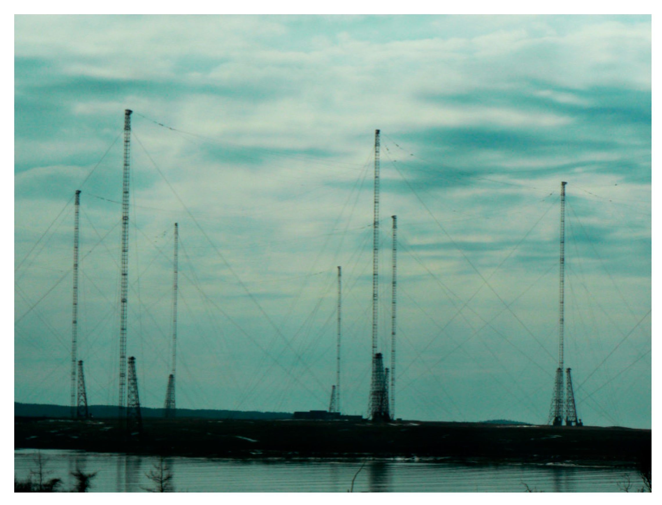
Ultra low frequency (ULF, below 3 Hz)/extremely low frequency (ELF, 3-3000 Hz)/very low frequency (VLF, 3–30 kHz) [1] waves are important not only for the navigation, communication, and detection of underground targets, but also for the precipitation of energetic electrons in radiation belts, in order to protect astronauts and spacecrafts operating in these regions [2]. This is because, firstly, ULF/ELF/VLF waves can travel thousands of kilometers in the Earth-ionospheric waveguide. Secondly, ULF/ELF/VLF waves can propagate upwards, into the magnetosphere. The magnetosphere is a large, natural plasma laboratory that is filled with a large number of high-energy electrons. The energy of these high-energy electrons ranges from about ~100 keV to several MeV, and electrons with a higher energy (>2 MeV) are called “relativistic electrons” or “killer electrons”, which can damage or even “kill” satellites. These “killer electrons” can be precipitated through the process of wave-particle interactions with ULF/ELF/VLF waves. This effect is of great practical significance with regards to eliminating the natural radiation belts or artificial radiation belts caused by high-altitude nuclear explosions [3,4,5]. However, there are some disadvantages of directly transmitting ULF/ELF/VLF waves by ground-based antenna arrays, such as the very large floor space, poor flexibility, low radiation efficiency, and high costs of use and maintenance, so there are difficulties in building such antenna arrays [6,7]. For example, the US Navy’s VLF antenna (as shown in Figure 1) consists of 26 towers and the height of each is 850 to 1000 ft. Moreover, the power of 18 MW consumed by the antenna is obtained from a dedicated power plant [8]. Furthermore, in the 1960s, the US Navy devised a plan to build an ELF antenna called Project Sanguine, which would have taken up 41 percent of the area of Wisconsin, but this project never came to fruition, mainly due to its overwhelming cost and the potential environmental impact [9]. Based on the above reasons, alternate methods are in demand.
Ionospheric heating by high power, high frequency (HF, 3–30 MHz) [10] radio waves is a method of artificially modifying the ionosphere by transmitting high frequency radio waves that can interact with ionospheric plasma and excite a series of non-linear physical processes. The study of ionospheric heating by high power high frequency radio waves is an interdisciplinary field of radio wave propagation, space science, and plasma physics. It has always been an important research direction of space physics and radio physics. The theoretical study of ionospheric heating includes two kinds of non-linear effects: (1) The thermal effect dominated by Ohmic heating and (2) parametric instability and electron acceleration due to the electric wave field.
Ionospheric modulated heating by high power HF waves is carried out by transmitting HF waves modulated by ULF/ELF/VLF waves into the ionosphere, so that the ionosphere radiates expected ULF/ELF/VLF waves under a series of non-linear effects. With the continuous improvement of theoretical and experimental research, modulated heating has become one of the most significant applications of ionospheric heating, consisting of a series of modulation methods based on different mechanisms. Streltsov et al. [11] reviewed the various modulation methods and provided an excellent summary of experimental and theoretical investigations regarding the different ULF/ELF/VLF wave generation mechanisms. This review paper is focused on the characteristics of each modulation method and discusses topics that have not been covered in previous reviews, such as the controversy of Beat Wave Modulation and the new theory of Thermal Cubic Non-Linearity. In particular, the characteristics of various modulation methods are summarized and compared and two possible methods for resolving the controversy of Beat Wave Modulation are proposed.
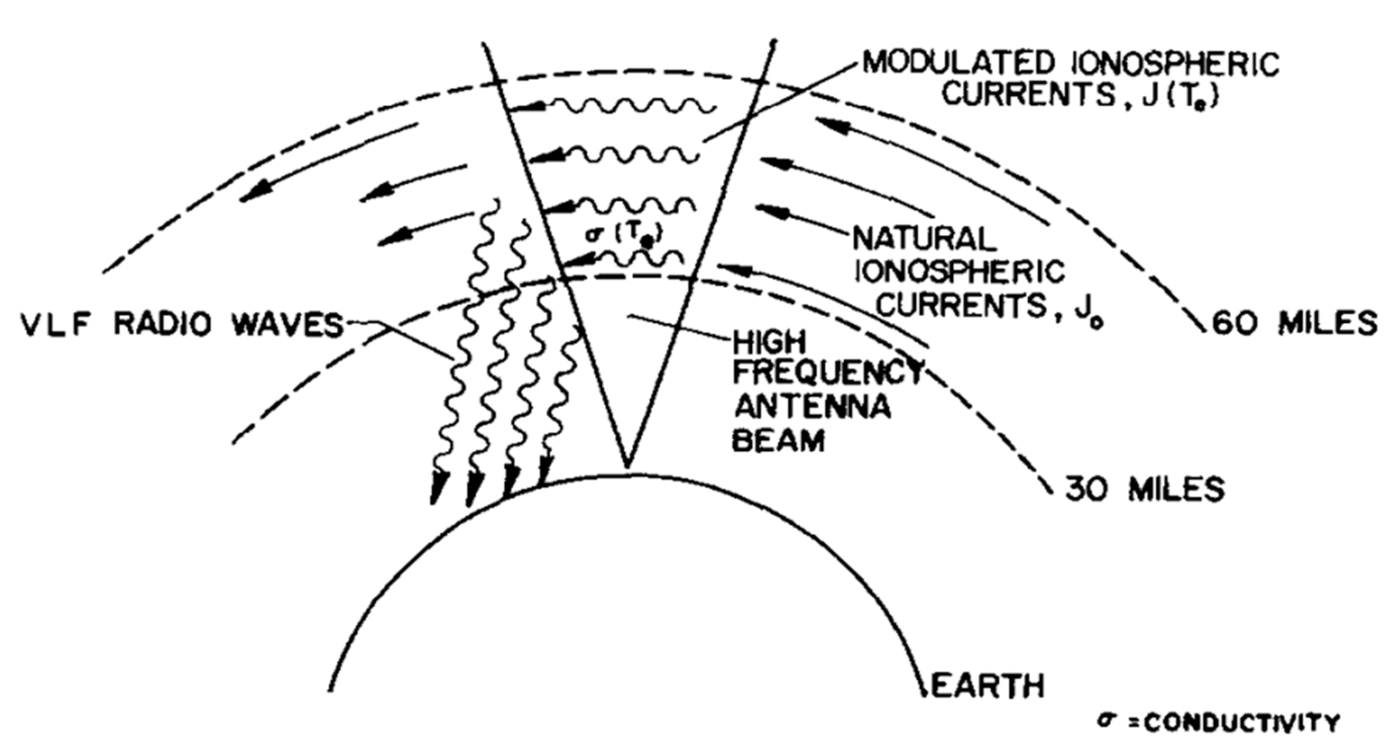
The idea of generating ULF/ELF/VLF waves by ionospheric modulated heating was first proposed by Willis and Davis [12], and was soon tested successfully for the first time by Getmantsev et al. [13]. Its basic principle is that the high frequency, high power transmitter “heater” is switched on and off with the frequency of the desired ULF/ELF/VLF waves, giving rise to increases and decreases of the local electron temperature with the modulation frequency. Such periodic changes in the electron temperature cause corresponding changes in the electron density and conductivity, generating the modulation current. In the presence of an electrojet in the ionosphere, the modulated current enhances the current and radiates the low frequency signal (as shown in Figure 2 [14]). This method is called Amplitude Modulation (AM). Several other modulation methods that have the same basic principle as AM have been categorized as improved methods based on AM and are introduced in Section 2.1. The physical mechanism of AM (as well as other improved methods based on AM) is based on Ohmic heating, whose essence is that ionospheric electrons obtain energy under the action of high frequency radio waves, and transfer the energy by colliding with ions and neutral particles, which causes the heating of ions and neutral particles in the ionosphere. However, the changes of temperature of ions and neutral particles are negligible compared to the change of temperature of electrons because the mass of electrons is negligible compared to the mass of ions and neutral particles.
The emergence of AM gave people a new perspective, and on this basis, scientists have carried out numerous theoretical investigations and experiments in Russia, Europe, and the United States for decades [11]. Information on the most representative heaters in the world carrying out modulated heating is shown in Table 1 [11,15,16].
Based on these heaters, many important experiments have been carried out in conjunction with observations of satellites (such as FAST (Fast Auroral Snapshot Explorer) [17,18] and DEMETER (Detection of Electro-Magnetic Emissions Transmitted from Earthquake Regions) [19,20,21]).
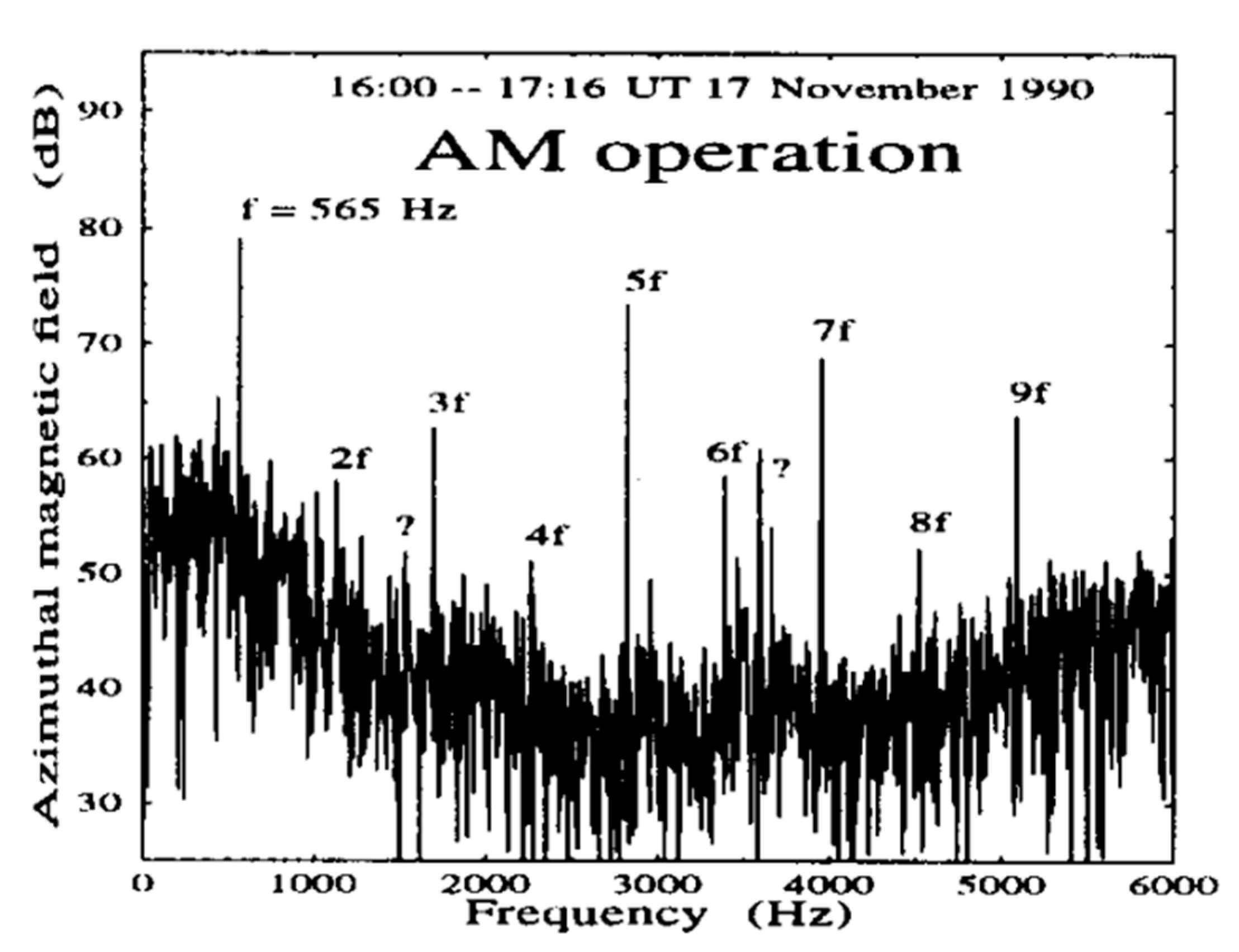
However, both theoretical and experimental investigations have illustrated that the efficiency of Amplitude Modulation is very low. Moore et al. [22] carried out experiments in HAARP which adopted sinusoidal Amplitude Modulation to generate 2125 Hz ELF waves and found that the transformation efficiency (HF to ELF) is only ~0.0004–0.0032%. Stubbe et al. [23] found that Amplitude Modulation can only be used for generating waves whose frequency is less than 23 kHz, which is caused by the insufficient change of the electron temperature during short periods of modulated heating. Improving the generation efficiency and expanding the frequency range of generated low frequency waves have been the focus of research. In addition, as shown in Figure 3, which presents an amplitude spectra of the ELF signals generated by AM during an experiment at EISCAT [24], it is also important to reduce the harmonic component of generated low frequency waves to improve the signal quality.
On the basis of traditional Amplitude Modulation, Rietveld et al. [25] established a theoretical model by combining experimental results and concluded that the electron heating time constant is shorter than the electron cooling time constant when modulating the Hall conductivity in the D region. Papadopoulos et al. [26] proposed two methods for improving the efficiency of AM: (1) Sweeping the antenna beam over an area on a time scale faster than the cooling rate at the heating altitude, which is an application of the difference between the electron heating time constant and electron cooling time constant mentioned above, and (2) modulating the Pedersen conductivity in the E region (90–100 km), which can be achieved by beating two HF waves at the local plasma frequency, or using short pulse HF waves. Cohen et al. found that the efficiency of AM decreases with an increase of the incident HF wave frequency and increases with an increase of the effective radiated power (ERP), beam width, and heating area, which is consistent with the first method proposed by Papadopoulos et al. [26] mentioned above and was verified by experiments at HAARP [10]. Larchenko et al. [27] found that there is a strong correlation between the strength of ELF/VLF waves generated by AM and the equivalent current, which is an infinitely thin sheet of current located at an altitude of 100 km. Yang et al. [28] pointed out that AM with an X wave is more efficient than that with an O wave; in order to obtain better ELF/VLF generation, the optimal frequency of HF waves was found to be 0.8~0.9 and 0.75~0.85 times for the O wave and X wave, respectively.
2. Mechanisms of Modulating ULF/ELF/VLF Waves
In general, the methods employed for modulating low frequency waves can be divided into several categories.
2.1. Improved Methods Based on Traditional Amplitude Modulation
2.1.1. Beam Painting
Beam Painting (BP) was proposed by Papadopoulos et al. [29]. The idea of this approach is that the time constants of electron heating and cooling in the ionosphere caused by switching on and off the heater are different and in most cases, the heating time constant is much lower than the cooling time constant [25]. The narrow beam HF waves are therefore made to heat each point in the larger ionospheric region, which is expected to be heated with a constant heating time, and the HF beam is quickly moved to the next point and returns to the first point before it cools completely (that is, t < cooling constant time). Therefore, this method can effectively expand the heating area to achieve the purpose of improving the modulation efficiency, which means that the key aspect of BP is that the heating time constant is much smaller than the cooling time constant. Barr et al. [30] studied the modulation efficiency of BP and found that the source of fundamental frequency and odd harmonics of ELF waves is located in a higher ionosphere, where the heating time constant is approximate to the cooling time constant, so the modulation efficiency of BP is not significantly improved compared with AM. On the other hand, the source of even harmonics of ELF waves is located in a lower ionosphere, where the heating time constant is more than an order of magnitude lower than the cooling time constant, so BP can significantly improve the modulation efficiency in the lower ionosphere.
2.1.2. Geometric Modulation
Cohen et al. [31] reported a method called Geometric Modulation (GM). This method is based on controlling the incidence direction of the HF wave, which causes the HF beam to scan the ionosphere in certain geometric patterns (such as circle sweep, line sweep, sawtooth sweep, and so on), in order to modulate the electrojet. Unlike BP, GM adopts a continuous wave (CW), the geometric motion of the CW in space replaces the periodic on-off of the heater, and the period in which a scan is completed matches the frequency of the modulated low frequency wave. On the basis of experiments at HAARP, Cohen et al. [31] found that GM is less efficient than AM when the modulated frequency is lower than 2 kHz, but significantly more efficient when the modulated frequency is higher than 3 kHz. In particular, the enhancement effect of ELF/VLF signals generated by GM compared to AM is more obvious (7–11 dB) for long distance observations. Furthermore, Cohen et al. [31] pointed out that GM has directional dependence. For example, the low frequency signals generated along the scanning direction were significantly stronger than those generated perpendicular to the scanning direction under line sweep.
In 2009, Moore and Rietveld [32] illustrated that GM is essentially the oblique AM modulation mentioned by Barr et al. [33]. In response to this, Cohen et al. [34] explained the difference between GM and oblique AM modulation in terms of the generation efficiency and geometric effects, and argued that the mechanism of GM is close to the two-element phased array modulation mentioned by Barr et al. [35]. Furthermore, by utilizing the new upgrade ability at HAARP, it has been proven that GM is more complicated than both oblique AM and two-element phased array modulation [34]. Therefore, Cohen et al. [34] emphasized that GM is an “unprecedented technique”.
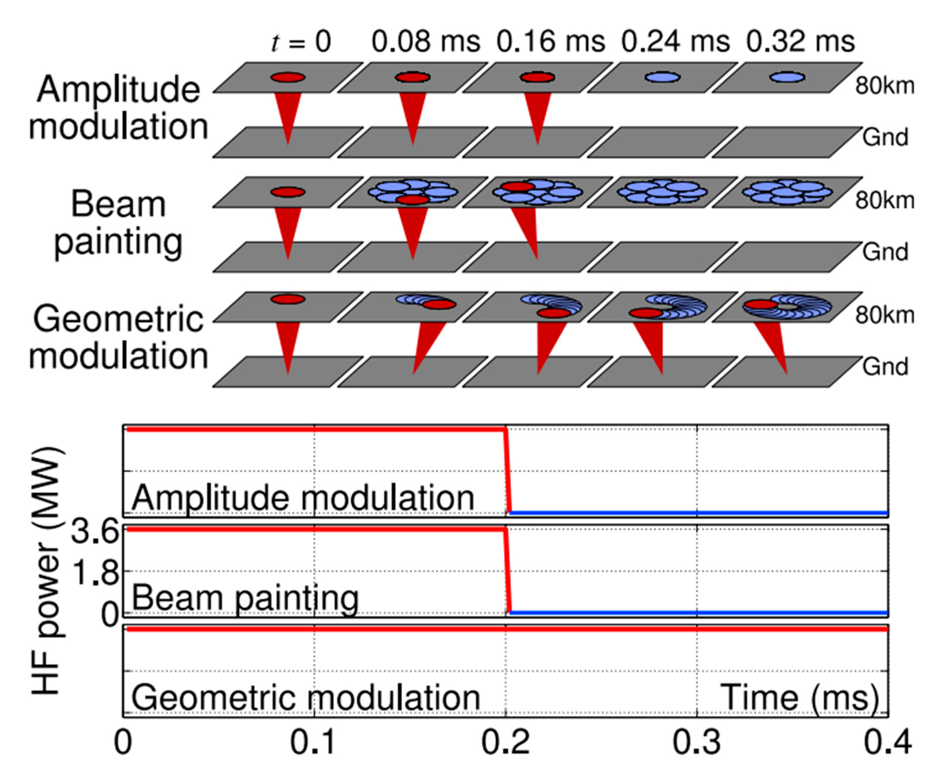
As mentioned in Section 2.1.1, BP is also a technique employed for modulated heating by controlling the movement of HF beams, so Cohen et al. quantitatively compared AM, BP, and GM through experiments and theoretical models and found that, compared with AM, BP is suitable for modulating waves in a lower frequency range, and the enhancement of excitation is mainly concentrated near the heating site; in contrast, GM can be more efficient at longer distances from the heating site [36,37]. The characteristic “a level of directionality” of Geometric Modulation was also verified. Recently, Robinson and Moore [38] proposed a method called the “optimized beam painting algorithm (OBP)”, which changes the azimuth and zenith angles of the heater to construct a phased array of the ELF/VLF source in the ionosphere. On the basis of experimental results performed over 1200 times at HAARP, they concluded that, compared to vertical AM, oblique AM, and GM, OBP can increase the received signal amplitudes of ELF/VLF waves. A schematic comparison of AM, BP, and GM is shown in Figure 4.
2.1.3. Preheating
The generation efficiency of ULF/ELF/VLF waves can be significantly improved by “preheating” the modulation region using HF waves before modulated heating, for two reasons. Firstly, preheating reduces the electron-ion recombination coefficient, resulting in an increased electron density and current density in the ionosphere, and secondly, preheating reduces low altitude self-absorption to sharpen the density profile, which leads to more efficient heating. This method was proposed by Milikh and Papadopoulos [39], who demonstrated that preheating could increase the signal intensity of low frequency waves generated by modulated heating by up to 7 dB.
2.1.4. Dual-Beam HF Modulation
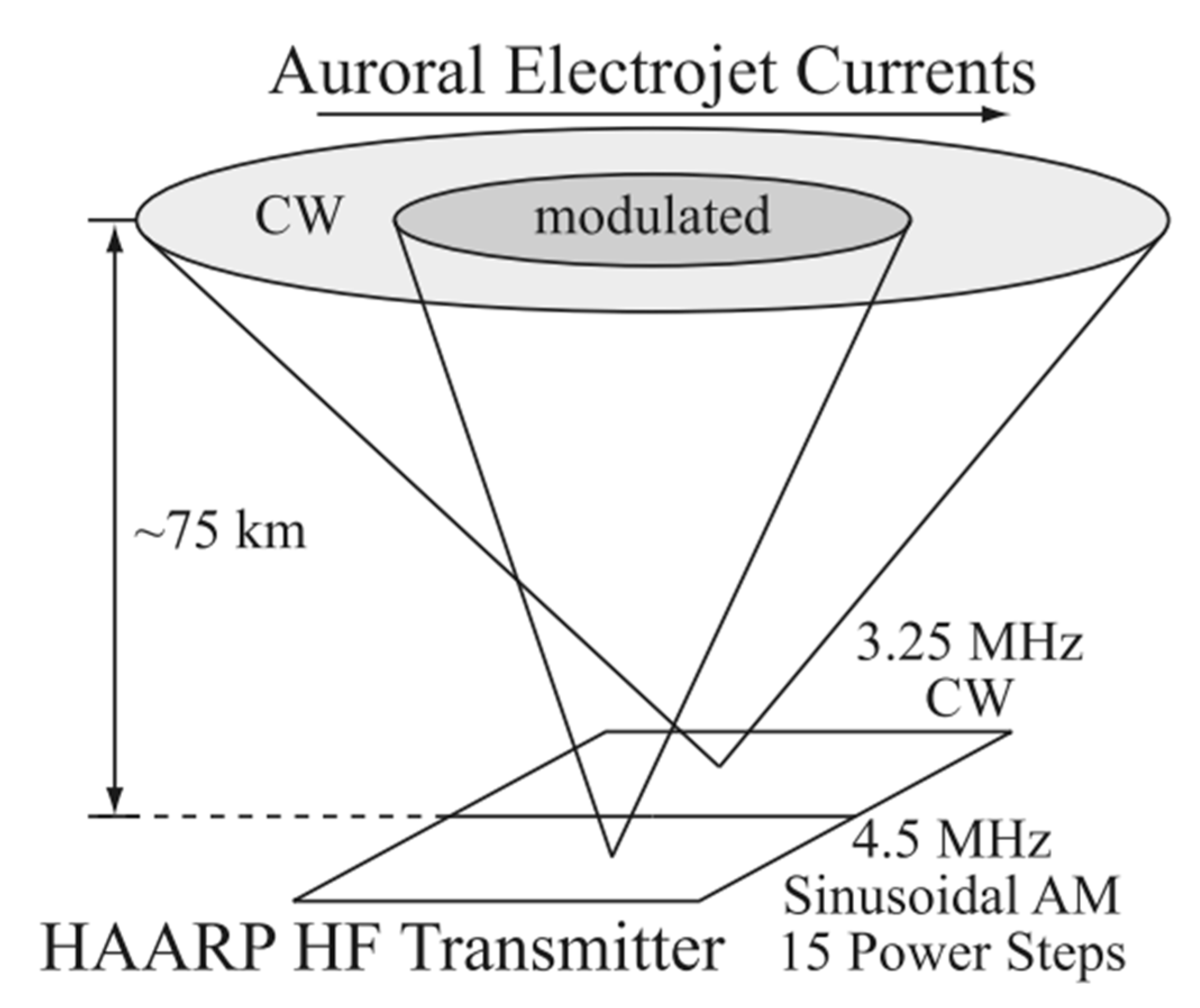
Moore and Agrawal [40] proposed a method using continuous waves and HF waves modulated by the ELF/VLF frequency simultaneously to generate corresponding ELF/VLF waves, and this method is called Dual-Beam HF Modulation (as shown in Figure 5). On the basis of experiments at HAARP and the establishment of a theoretical model, Moore and Agrawal [40] found that continuous waves led to a decrease in the modulation efficiency, so this is not a preferable way of generating ELF/VLF waves compared to AM. On the other hand, further analysis [41] indicated that the intensity of ELF/VLF waves is sensitive to the altitude distribution of the electron density and electron temperature in the D region, so Dual-Beam HF Modulation could be an applicable D-region diagnostic. Gołkowski et al. [42] found that dual HF beams with AM (both beams are modulated HF waves at ELF/VLF with a phase offset) can also be a potential diagnostic method for the D region; that is, when two HF beams are both transmitted vertically, the net modulation of the electrojet is that of the sum of the power envelopes of both beams of the first order. Deviation from the power envelope sum as a function of the phase is caused by the characteristics of the D-region plasma gradients. The deviations can be modeled and used as a D region diagnostic, although this may require experiments with finer and more rapid ELF phase stepping guided by comprehensive modeling. This conclusion is supported by Maxworth et al. [43].
In addition, there are several other methods relevant to AM. Gołkowski et al. [44] proposed that cross modulation could be used to generate waves in the range of 630 Hz~37 kHz. The intensity of ELF/VLF waves generated by this method is an order of magnitude weaker than AM, although it is able to produce waves with a wider frequency range than AM (>30 kHz). Furthermore, the authors mentioned that the harmonics modulated by AM can also generate waves higher than 30 kHz with a similar intensity to cross modulation. Villaseñor et al. [45] compared traditional AM with a method called the demodulation mode (DM). The process of DM is to conduct vertical heating during the former half time of a modulation period, and the beam is then separated into heat regions on either side of the vertical position, subdividing the array into two sub-arrays during the latter half time of a modulation period. The experimental results indicated that the intensity of ELF/VLF waves generated by DM is only about half that of AM. The main reason why the modulation efficiency of DM is lower than that of AM is because of the smaller disturbance amplitude of the electron temperature. Therefore, DM is no longer accepted as an effective method of modulated heating and is not reported in previous reviews. However, DM illustrates the importance of maximizing the efficiency of electron temperature perturbation during the electrojet modulation process, which includes three aspects: Firstly, the increase of the electron temperature should be improved as much as possible during the heating process; secondly, the electron temperature should be restored to the initial state as far as possible during the cooling process; and finally, the duty cycle should be set as a suitable value to avoid stable states of the electron temperature during the heating or cooling process.
The above methods can be classified as improvements to AM because they are essentially the same as AM, which changes the electron temperature in the D region and lower E region periodically by switching on and off the heater or other equivalent methods that can achieve the same effect, thus inducing periodic changes of conductivity and superimposing them on the electrojet to produce ELF/VLF waves.
In this context, it can be seen that the modulation efficiency of AM and its improved methods are inevitably affected by the strength of the background electrojet and the heating and cooling time constants. The heating time constant can usually be shortened by increasing the power of the heater, but the strength of the electrojet in the background and cooling time constant are difficult to control artificially. The strength of the electrojet limits the time and location of modulated heating: Ionospheric currents at mid-latitudes are weak in general, so AM is more suitable for modulated heating in the polar and equatorial regions. However, the polar electrojet does not exist all the time and is hard to predict. Furthermore, at present, there is not a suitable facility for carrying out experiments in equatorial regions. In addition, as the frequency of modulation increases, the deficiency of the cooling time becomes more and more obvious, resulting in a serious attenuation of the signal strength [46]. Therefore, scientists have proposed several other modulation mechanisms that are independent or less dependent on the electrojet, as well as the heating and cooling time.
2.2. Beat Wave Modulation
VLF, ELF, and ULF waves can be modulated by utilizing two continuous waves with a frequency difference of f1 (f1 is the ELF/VLF modulated frequency) transmitted by two sub-arrays [24,47], and this mechanism is called Beat Wave Modulation (BW). The main difference between Dual-Beam HF Modulation and Beat Wave Modulation is that the two sub-arrays of Dual-Beam HF Modulation emit continuous waves and discontinuous waves modulated by ELF/VLF, respectively, and the carrier frequency of these two waves can be the same. On the other hand, the two sub-arrays of Beat Wave Modulation emit two continuous waves with different frequencies. Villaseñor et al. [45] demonstrated that the low frequency signals excited by AM are stronger than those excited by BW at almost all the modulated frequencies, although BW can produce a more stable low frequency signal in some cases. In addition, the excitation efficiency of the X-mode wave is higher than that of the O-mode wave by a factor of two, either using AM or BW modulation. The experimental observations of Barr and Stubbe [24] confirmed the conclusion of Villaseñor et al. [45]. Furthermore, Barr and Stubbe [24] also predicted that the modulation efficiency of BW might be higher than that of AM by adjusting the receiver position, distance of heating arrays, modulation frequency, and other parameters.
On these bases, Kuo et al. [47,48] proposed that inducing disturbance of the ponderomotive force in the F region by BW may be an electrojet-independent modulation technique, and VLF waves were successfully modulated when the ionospheric current was weak. According to numerical simulation and experimental verification, Kuo et al. [48] concluded that BW is an electrojet-independent modulation method. They also concluded that BW is more suitable for modulating VLF waves with a higher frequency, and modulation by the X-mode wave is more effective than that by the O-mode wave. However, Jin et al. [49] demonstrated that the weak intensity of the electrojet sometimes does not mean that low frequency waves are not generated in the D region, because the intensity of modulated low frequency waves is also affected by the D region electron density profile. Subsequently, Kuo et al. [47] further determined that the source region of VLF waves generated by BW was located in the F layer, and pointed out that the modulation effect of underdense heating (i.e., the frequency of the HF wave is greater than the maximum ionospheric plasma frequency in a layer during the process of ionospheric heating) was better than that of overdense heating (i.e., the frequency of the HF wave is lower than the maximum ionospheric plasma frequency in a layer during the process of ionospheric heating). Moore et al. [50] used the time-of-arrival (TOA) analysis method proposed by Fujimaru and Moore [51] to infer that the source region of BW was located in the D layer instead of the F layer and the theoretical model established by Cohen et al. [10] for D region collisional absorption confirmed this conclusion. However, Cohen et al. [10] also pointed out that the F layer BW modulation theory proposed by Kuo et al. [47,48] could not be ruled out at present, and needs to be further tested and verified. Therefore, it is still controversial whether the source region of ELF/VLF waves generated by BW modulation is located in the D layer [52,53,54,55,56] or F layer [57,58,59,60].
2.3. Thermal Cubic Non-Linearity Method
Thermal Cubic Non-Linearity was first proposed by Ginzburg [61]. This mechanism was initially used as a modulation method for generating ELF/VLF waves by Kotik and Ermakova [62]. In this method, two HF waves with frequencies and , respectively, where ( is the frequency that needs to be modulated), are injected into the ionosphere [62,63]. Moore et al. [64] applied TOA analysis to experimental observations to determine whether the source of the thermal cubic ELF and VLF is located in the collisional D region.
In contrast to the previous conclusion [62,63], which suggests that the wave induces a collision frequency oscillation at and the oscillation then mixes with the polarization current density of the wave to produce an ELF/VLF source current density at frequency , Moore et al. [64] proposed that the ELF and VLF source is mainly induced by the interaction between collision frequency oscillations at frequency and the polarization current density associated with the HF wave at frequency .
In addition, ELF/VLF waves generated by Thermal Cubic Non-Linearity are significantly weaker than AM in the 1–5 kHz range [65] and 16–20 kHz range [50]. ELF/VLF waves generated by Thermal Cubic Non-Linearity are also weaker than the Ionospheric Current Drive mechanism, which will be introduced in Section 2.4, especially at a lower frequency (<100 Hz) [66], but cubic generation is stronger at higher frequencies (>10 kHz) [64]. Moreover, Thermal Cubic Non-Linearity may be used to generate ELF waves employing VLF waves [67] because VLF waves are more effective than HF waves when heating the ionosphere.
2.4. Ionospheric Current Drive
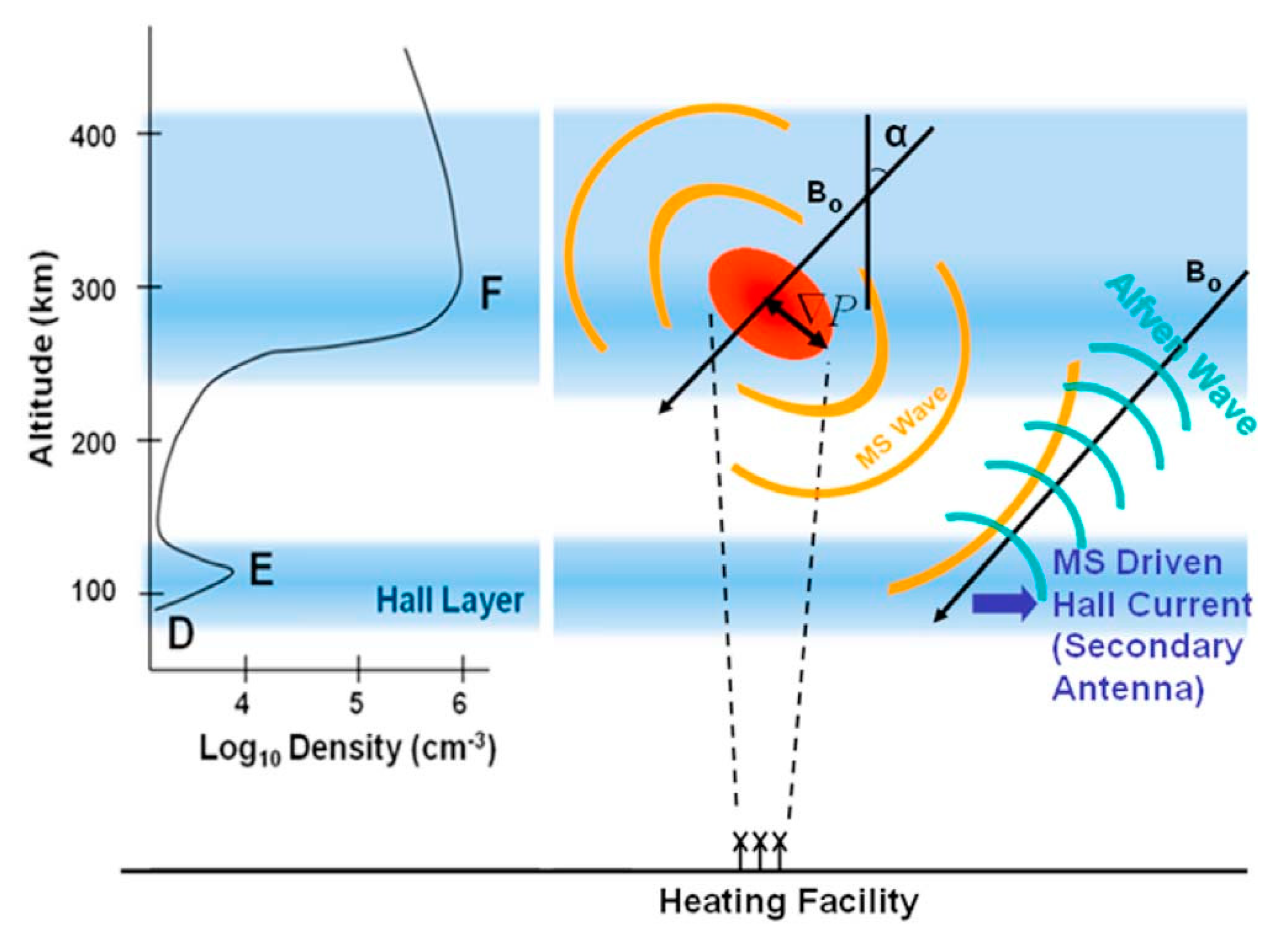
The Ionospheric Current Drive (ICD) was proposed by Papadopoulos et al. [66] and verified by experiments for the first time [68] as a method for generating low ELF/ULF frequency waves without relying on the presence of electrojets, so this mechanism can be used to modulate ELF/ULF waves in the mid-latitude region. The effect relies on modulated F region HF heating to form a local diamagnetic current, which then generates Magneto-Sonic (MS) waves that modulate Hall currents when they reach the D-E region. The modulated Hall currents inject ELF waves downward, into the Earth-ionosphere waveguide, as well as Shear Alfvén Waves (SAW) upward, into the magnetosphere (as shown in Figure 6). Based on the cold plasma model, Eliasson et al. [69] constructed the numerical model of ELF/ULF waves excited by the ICD method, as well as the propagation model of MS waves and ELF/ULF waves. By considering the characteristics of the magnetic field and radio wave propagation in the mid-latitude ionosphere, Sharma et al. [70] studied the excitation of ELF waves by the ICD method in the mid-latitude region and its propagation in the ionosphere and magnetosphere. Xu et al. [71] studied the generation and propagation of ULF waves modulated by the ICD mechanism under different background ionospheric parameters and modulation frequencies through numerical simulation. Streltsov et al. [72] found that the intensity of ELF waves was significantly enhanced when modulated with the frequency of Schumann resonance. They suggested that the ELF waves generated in their experiments may be the result of conductivity modulation in the lower ionosphere and ICD in the F region, but the respective contribution of the two mechanisms cannot be quantitatively analyzed due to the lack of high resolution altimeter data. Moreover, the experiments of Papadopoulos et al. [68] adopted O wave heating, while subsequent experiments at HAARP [72] and EISCAT [73,74] have proved that the X wave can cause significant disturbance of the electron temperature and electron density in the F layer, so X wave heating can also effectively trigger the ICD mechanism.
2.5. LH-to-Whistler Mode Conversion
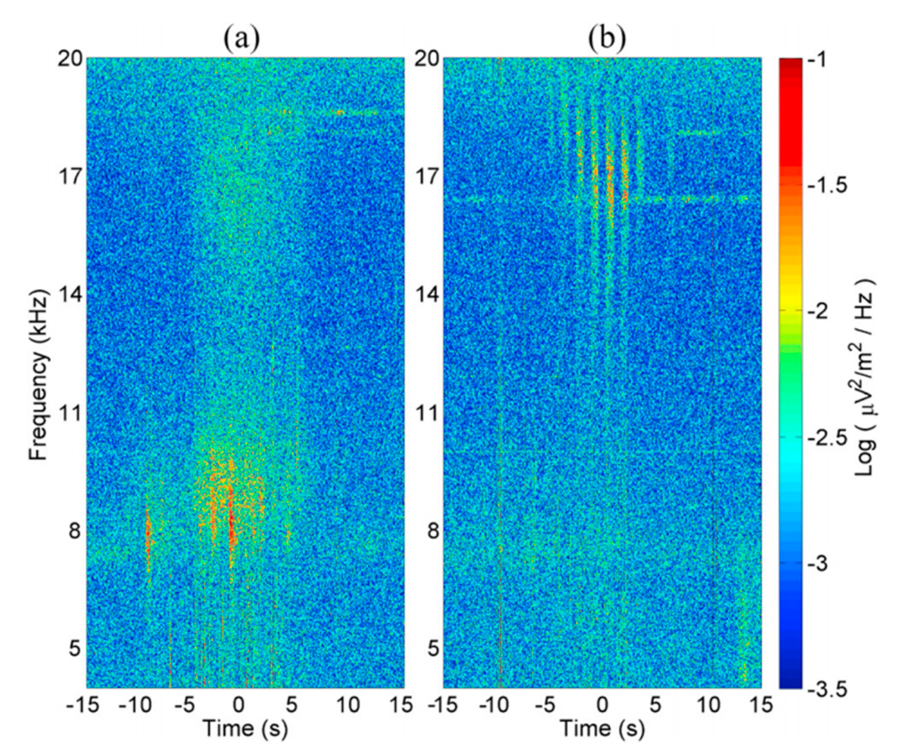
At the upper hybrid (UH) height (, where is the frequency of the electromagnetic wave, is the plasma frequency, and is the electron gyrofrequency), ordinary HF waves can stimulate thermal parametric instability, i.e., the HF wave decays into high frequency plasma waves and low frequency plasma waves or the small scale field-aligned irregularity. The thermal parametric instability includes (1) thermal oscillating two-stream instability, where the HF wave decays into two UH waves with opposite propagation directions and small scale field-aligned irregularities, and (2) thermal parametric decay instability, where the HF wave decays into a high frequency UH wave and a low frequency lower hybrid (LH) wave [75]. Vartanyan et al. [20] analyzed two heating experiments at HAARP with the observation from DEMETER and found that F region ionospheric heating by continuous waves could also generate VLF waves of certain frequencies, and the whole process is independent of the electrojet. This method is based on the mode conversion of LH waves, so it can only be used for generating VLF waves in the corresponding frequency range of LH and its harmonic, as shown in Figure 7 (7–10 and 15–19 kHz, respectively). The mechanism of this method can be described as follows: The HF continuous wave interacts with the plasma in the upper hybrid layer to excite LH waves, and the VLF wave is then generated by the mode conversion of LH waves. Vartanyan et al. [20] proposed two points: (1) The VLF waves observed at the LH frequency are due to the interaction of the LH waves with meter-scale field-aligned striations, and (2) the VLF waves at twice the LH frequency are due to the interaction of two counter propagating LH waves. This mechanism was also verified experimentally by Kuo and Lee [76].
Furthermore, Gigliotti et al. [77] carried out an experiment using Large Plasma Device (LAPD) at the University of California, Los Angeles (UCLA), to generate polarized SAW using a rotating magnetic field (RMF) source created via a phased orthogonal two-loop antenna. This was the first time that RMF controlled by a special antenna was formed. Although this was not a method for generating ELF/VLF waves by modulating HF waves, it was another way to generate ELF/VLF waves, instead of them being transmitted directly by the ELF/VLF antenna. Gigliotti et al. [77] also proposed the prospect of using satellites to carry such antennas to form RMF in the space and inject SAW into radiation belts. Subsequent three-dimensional numerical simulations and relevant experiments have demonstrated that the RMF mechanism can effectively generate SAW and low frequency whistler waves [78,79]. In recent years, the LAPD has further upgraded its devices [80,81] for further research in the future. Inspired by this method, De Soria-Santacruz et al. [82] theoretically designed a spaceborne antenna to excite low frequency waves.
3. Concluding Remarks
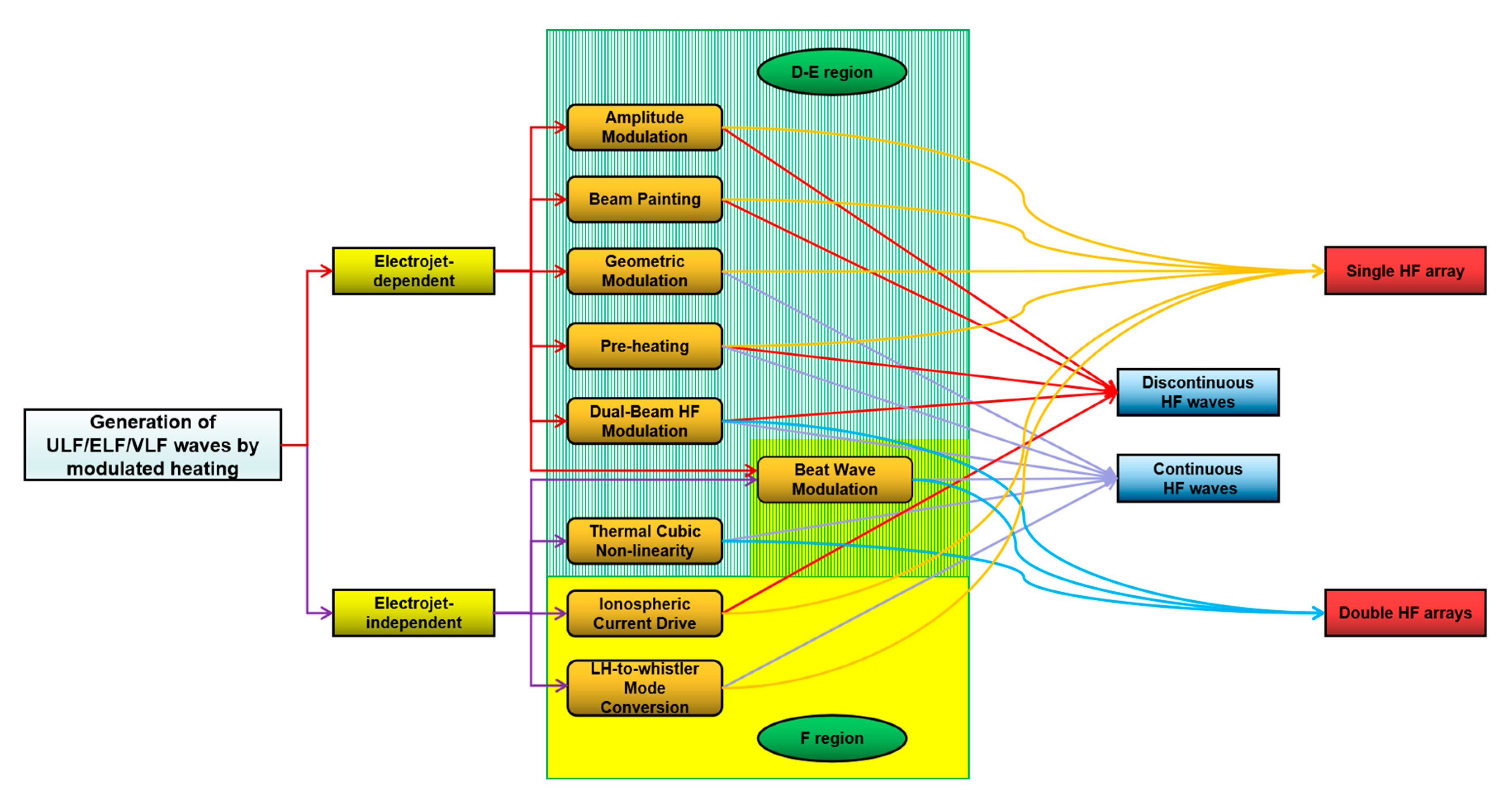
Over the past few decades, modulated heating has evolved from Amplitude Modulation to a number of modulation methods, which have different characteristics (as shown in Figure 8).
Firstly, according to the dependence of the electrojet, they can be divided into two methods. Amplitude Modulation, Beam Painting, Geometric Modulation, Preheating, and Dual-Beam HF Modulation all belong to electrojet-dependent modulation methods, which means that, in order to achieve better modulation effects, several strict spatio-temporal conditions must be met. In contrast, electrojet-independent modulation methods, such as Thermal Cubic Non-Linearity, Ionospheric Current Drive, and LH-to-Whistler Mode Conversion, expand the time and space scope of modulated heating. In addition, the mechanism of Beat Wave Modulation is still controversial.
Secondly, the different modulation methods can be divided into two types in terms of the source region of the modulated ULF/ELF/VLF waves. One is located in the D-E region, including Amplitude Modulation, Beam Painting, Geometric Modulation, Preheating, Dual-Beam HF Modulation, and Thermal Cubic Non-Linearity, whilst the other is located in the F region, including Ionospheric Current Drive and LH-to-Whistler Mode Conversion. Just like the mechanism, the source region of Beat Wave Modulation is also controversial. It is worth noting that although the source region of all electrojet-dependent modulation methods is located in the D-E region, it does not mean that all the modulation methods located in the D-E region are electrojet modulation methods because research in recent years has shown that Thermal Cubic Non-Linearity modulation is an electrojet-independent modulation method whose source region is located in the D region [64].
In addition, for some modulation methods, the electron temperature is modulated by discontinuous HF waves, such as Amplitude Modulation, Beam Painting, and Ionospheric Current Drive. For other methods, the process of modulated heating is carried out by transmitting continuous waves into the ionosphere, among which Geometric Modulation is a method that expands the modulation area by changing the elevation angle of HF waves. Therefore, it is a continuous wave modulation method for the whole modulation region, but a discontinuous wave modulation method for a certain spot in the modulation region; other continuous wave modulation methods are based on the frequency matching characteristics of HF waves, such as Beat Wave Modulation and Thermal Cubic Non-Linearity, or natural frequency characteristics of the ionosphere, such as LH-to-Whistler Mode Conversion. In addition, there are methods that transmit both continuous and discontinuous waves, such as Preheating and Dual-Beam HF Modulation; however, they are essentially consistent with the discontinuous wave modulation.
In terms of the number of HF heating arrays, some modulation methods can be carried out using a single array, such as Amplitude Modulation, Beam Painting, Geometric Modulation, Preheating, Ionospheric Current Drive, and LH-to-Whistler Mode Conversion, while other modulation methods require two separate HF heating arrays to work together, such as Dual-Beam HF Modulation, Beat Wave Modulation, and Thermal Cubic Non-Linearity. Considering that the effective radiation power will be greatly reduced when the heating array is divided into two subarrays, a higher performance of the heater is required for double array modulation methods.
Finally, the suitable range of modulation frequency differs for different modulation methods (as shown in Table 2). AM is mainly suitable for the modulation of ELF and lower VLF waves, which are mainly determined by the time scale of ionospheric heating and cooling. The time scales of the change of the electron temperature in both heating and cooling processes in the D-E layer are~ms. Therefore, when the modulation frequency is in the ULF band, the electron temperature and the corresponding conductivity always reach stability within a period of time far shorter than the modulation period, which means that the ionosphere is essentially in its natural state for most of the modulation process. On the other hand, when the modulation frequency is at a very high VLF range, the electron temperature and the corresponding conductivity cannot reach a stable state within the modulation period, which indicates inadequate modulation. Compared with AM, BP is suitable for modulating waves in a lower frequency range, and GM is less efficient than AM when the modulated frequency is lower than 2 kHz, but significantly more efficient when the modulated frequency is higher than 3 kHz. Preheating could increase the signal intensity of AM by up to 7 dB; however, the continuous wave of Dual-Beam HF Modulation would lead to a decrease in the modulation efficiency of AM. BW is more effective than AM in the VLF range. ELF/VLF waves generated by Thermal Cubic Non-Linearity are significantly weaker than AM in the 1–5 and 16–20 kHz range. ICD is more suitable for the modulation of waves in the ULF range. LH-to-Whistler Mode Conversion can only be used for generating VLF waves in the corresponding frequency range of LH and its harmonic (7–10 and 15–19 kHz, respectively).
4. Prospect
Future research on the generation of ULF/ELF/VLF waves by ionospheric modulated heating using high power, high frequency waves needs to explore the development of a modulation method that is less dependent on the ionospheric environment, with a high modulation efficiency and stable signal. For this goal, the following aspects should be focused on:
1. Investigate the controversy regarding the mechanism and source region of Beat Wave Modulation (two possible methods for solving this controversy are introduced in points 2 and 4), as well as new insight into the mechanism of Thermal Cubic Non-Linearity;
2. Investigate the possibility of the combination of existing modulation methods to explore new modulation methods. For example, the influence of preheating on other modulation methods deserves to be studied according to the existing research conclusion that preheating can improve the modulation efficiency of Amplitude Modulation. In addition, preheating may become a useful localization method of the source region of BW modulation because of its different effects on Beat Wave Modulation in different source regions;
3. Explore the possibility of non-linearity effects as the theoretical basis of modulated heating. Recent studies have indicated that non-linear effects excited by parametric instability, such as ponderomotive force and mode conversion, are important in modulated heating. Therefore, the effects of other non-linear need to be investigated;
4. Explore utilizing multiple observational means (research ships, such as Tangaroa [83,84], and satellites, such as RESONANCE [85,86]) simultaneously, for example, the localization method proposed by Demekhov et al. [87], which utilizes simultaneous ground and space observations, may be an effective method for resolving the controversy of the source region of Beat Wave Modulation;
5. Investigate electrojet-independent modulation methods. It is important to carry out experiments using heaters at middle and low latitudes, such as SURA (56.13° N, 46.1° E) [11] and Arecibo (18° N, 67° W, no longer available, but expected for building and using other heaters at low latitudes like Arecibo in the future) [88], as well as receivers at middle and low latitudes, such as the WHU (Wuhan University) ELF/VLF receiver (30.54° N, 114.37° E) [89,90].
Author Contributions
Investigation, Z.G.; writing—original draft preparation, Z.G. and F.H.; writing—review and editing, Z.G.; supervision, F.H. and H.F. All authors have read and agreed to the published version of the manuscript.
Funding
This research was funded by the National Natural Science Foundation of China (grant number 41804149) and China Scholarship Council.
Conflicts of Interest
The authors declare no conflict of interest.
References
- Dea, J.Y.; Hansen, P.M.; Boerner, W.-M. Low-frequency (ULF/ELF/VLF) radio polarimetry and some applications. In Radar Polarimetry; International Society for Optics and Photonics: Bellingham, WC, USA, 1993; Volume 1748, pp. 23–30. [Google Scholar] [CrossRef]
- Alpert, Y.L. Longitudinal ELF to LF electromagnetic oscillations and waves generated in the ionosphere under the influence of strong high-frequency electric field. J. Geophys. Res. 1995, 100, 289–304. [Google Scholar] [CrossRef]
- Inan, U.S. Multi-hop whistler-mode ELF/VLF signals and triggered emissions excited by the HAARP HF heater. Geophys. Res. Lett. 2004, 31, L24805. [Google Scholar] [CrossRef] [Green Version]
- Cairó, L.; Lefeuvre, F. Localization of sources of ELF/VLF hiss observed in the magnetosphere: Three-dimensional ray tracing. J. Geophys. Res. 1986, 91, 4352–4364. [Google Scholar] [CrossRef]
- Gu, X.; Zhao, Z.; Ni, B.; Shprits, Y.; Zhou, C. Statistical analysis of pitch angle distribution of radiation belt energetic electrons near the geostationary orbit: CRRES observations. J. Geophys. Res. Space Phys. 2011, 116, A01208. [Google Scholar] [CrossRef] [Green Version]
- Chang, S.S. Propagation of ELF/VLF Waves Excited by IONOSPHERIC Modulation and the Resonant Interaction with Energetic Electrons in the Magnetosphere. Ph.D. Thesis, Wuhan University, Wuhan, China, April 2014. [Google Scholar]
- Chang, S.; Zhu, Z.; Ni, B.; Cao, X.; Luo, W. Resonant scattering of energetic electrons in the outer radiation belt by HAARP-induced ELF/VLF waves. Adv. Space Res. 2016, 58, 1219–1228. [Google Scholar] [CrossRef]
- Mysore Nagaraja, S. Going beyond Chu’s Limit: ULF Radiation with Directly Modulated Spinning Magnet Arrays. Master of Science, UCLA. Ph.D. Thesis, University of California, Berkeley, CA, USA, 2017. [Google Scholar]
- MHUGL. Available online: https://ss.sites.mtu.edu/mhugl/2019/10/30/project-sanguine-gecooper/ (accessed on 18 January 2021).
- Cohen, M.B.; Golkowski, M.; Lehtinen, N.G.; Inan, U.S.; McCarrick, M.J. HF beam parameters in ELF/VLF wave generation via modulated heating of the ionosphere. J. Geophys. Res. Space Phys. 2012, 117, A05327. [Google Scholar] [CrossRef]
- Streltsov, A.V.; Berthelier, J.-J.; Chernyshov, A.A.; Frolov, V.L.; Honary, F.; Kosch, M.J.; McCoy, R.P.; Mishin, E.V.; Rietveld, M.T. Past, Present and Future of Active Radio Frequency Experiments in Space. Space Sci. Rev. 2018, 214. [Google Scholar] [CrossRef] [Green Version]
- Willis, J.W.; Davis, J.R. Radio frequency heating effects on electron density in the lower E region. J. Geophys. Res. 1973, 78, 5710–5717. [Google Scholar] [CrossRef]
- Getmantsev, G.G.; Zuikov, N.A.; Kotik, D.S.; Mironenko, L.F.; Mitiakov, N.A.; Rapoport, V.O.; Sazonov, I.A.; Trakhtengerts, V.I.; Eidman, V.I. Combination frequencies in the interaction between high-power short-wave radiation and ionospheric plasma. Sov. Phys. JETP Engl. Transl. 1974, 20, 229–232. [Google Scholar]
- Ferraro, A.J.; Lee, H.S.; Allshouse, R.; Carroll, K.; Tomko, A.A.; Kelly, F.J.; Joiner, R.G. VLF/ELF radiation from the ionospheric dynamo current system modulated by powerful HF signals. J. Atmos. Solar-Terr. Phys. 1982, 44, 1113–1122. [Google Scholar] [CrossRef]
- Belikovich, V.V.; Grach, S.M.; Karashtin, A.N.; Kotik, D.S.; Tokarev, Y.V. The “Sura” facility: Study of the atmosphere and space (a review). Radiophys. Quantum Electron. 2007, 50, 497–526. [Google Scholar] [CrossRef]
- Rietveld, M.T.; Senior, A.; Markkanen, J.; Westman, A. New capabilities of the upgraded EISCAT highpower HF facility. Radio Sci. 2016, 51, 1533–1546. [Google Scholar] [CrossRef] [Green Version]
- Robinson, T.R.; Strangeway, R.; Wright, D.M.; Davies, J.A.; Horne, R.B.; Yeoman, T.K.; Stocker, A.J.; Lester, M.; Rietveld, M.T.; Mann, I.R.; et al. FAST observations of ULF waves injected into the magnetosphere by means of modulated RF heating of the auroral electrojet. Geophys. Res. Lett. 2000, 27, 3165–3168. [Google Scholar] [CrossRef] [Green Version]
- Kolesnikova, E.; Robinson, T.R.; Davies, J.A.; Wright, D.M.; Lester, M. Excitation of Alfven waves by modulated HF heating of the ionosphere, with application to FAST observations. Ann. Geophys. 2002, 20, 57–67. [Google Scholar] [CrossRef] [Green Version]
- Piddyachiy, D.; Inan, U.S.; Bell, T.F.; Lehtinen, N.G.; Parrot, M. DEMETER observations of an intense upgoing column of ELF/VLF radiation excited by the HAARP HF heater. J. Geophys. Res. 2008, 113, A10308. [Google Scholar] [CrossRef] [Green Version]
- Vartanyan, A.; Milikh, G.M.; Eliasson, B.; Najmi, A.C.; Parrot, M.; Papadopoulos, K. Generation of whistler waves by continuous HF heating of the upper ionosphere. Radio Sci. 2016, 51, 1188–1198. [Google Scholar] [CrossRef] [Green Version]
- Chang, S.; Ni, B.; Cao, X.; Zhang, X.; Zhu, Z.; Luo, W. Energetic Electron Diffusion by Modulated Heating of the Ionosphere. J. Geophys. Res. Space Phys. 2018, 123, 5516–5527. [Google Scholar] [CrossRef]
- Moore, R.C.; Inan, U.S.; Bell, T.F.; Kennedy, E.J. ELF waves generated by modulated HF heating of the auroral electrojet and observed at a ground distance of ∼4400 km. J. Geophys. Res. Space Phys. 2007, 112, A05309. [Google Scholar] [CrossRef] [Green Version]
- Stubbe, P.; Kopka, H.; Rietveld, M.; Frey, A.; Høeg, P.; Kohl, H.; Holt, O. Ionospheric modification experiments with the Tromsø heating facility. J. Atmos. Solar-Terr. Phys. 1985, 47, 1151–1163. [Google Scholar] [CrossRef]
- Barr, R.; Stubbe, P. ELF and VLF wave generation by HF heating: A comparison of AM and CW techniques. J. Atmos. Solar-Terr. Phys. 1997, 59, 2265–2279. [Google Scholar] [CrossRef]
- Rietveld, M.; Kopka, H.; Stubbe, P. D-region characteristics deduced from pulsed ionospheric heating under auroral electrojet conditions. J. Atmos. Solar-Terr. Phys. 1986, 48, 311–326. [Google Scholar] [CrossRef]
- Papadopoulos, K.; Chang, C.L.; Vitello, P.; Drobot, A. On the efficiency of ionospheric ELF generation. Radio Sci. 1990, 25, 1311–1320. [Google Scholar] [CrossRef]
- Larchenko, A.V.; Blagoveshchenskaya, N.F.; Pilgaev, S.V.; Beketova, E.B.; Fedorenko, Y.V. Relationship Between the Polar Electrojet Dynamics and the Amplitude of ELF/VLF Signal from the Ionospheric Source in the Modulated Ionospheric Heating Experiment. Radiophys. Quantum Electron. 2019, 62, 385–394. [Google Scholar] [CrossRef]
- Yang, J.T.; Wang, J.G.; Li, Q.L.; Che, H.Q.; Hao, S.J. Optimized analysis of ionospheric amplitude modulated heating parameters for excitation of very/extremely low frequency radiations. Plasma Sci. Technol. 2019, 21, 075301. [Google Scholar] [CrossRef]
- Papadopoulos, K.; Sharma, A.S.; Chang, C.L. On the efficient operation of a plasma ELF antenna driven by modulation of ionospheric currents. Comments Plasma Phys. Controlled Fusion 1989, 13, 1–17. [Google Scholar]
- Barr, R.; Stubbe, P.; Rietveld, M.T. ELF wave generation in the ionosphere using pulse modulated HF heating: Initial tests of a technique for increasing ELF wave generation efficiency. Ann. Geophys. 1999, 17, 759–769. [Google Scholar] [CrossRef]
- Cohen, M.B.; Inan, U.S.; Golkowski, M.A. Geometric modulation: A more effective method of steerable ELF/VLF wave generation with continuous HF heating of the lower ionosphere. Geophys. Res. Lett. 2008, 35, L12101. [Google Scholar] [CrossRef]
- Moore, R.C.; Rietveld, M.T. Comment on “Geometric modulation: A more effective method of steerable ELF/VLF wave generation with continuous HF heating of the lower ionosphere”. Geophys. Res. Lett. 2009, 36, L04101. [Google Scholar] [CrossRef]
- Barr, R.; Rietveld, M.T.; Stubbe, P.; Kopka, H. Ionospheric heater beam scanning: A realistic model of this mobile source of ELF/VLF radiation. Radio Sci. 1988, 23, 379–388. [Google Scholar] [CrossRef]
- Cohen, M.B.; Inan, U.S.; Gołkowski, M. Reply to comment by R. C. Moore and M. T. Rietveld on “Geometric modulation: A more effective method of steerable ELF/VLF wave generation with continuous HF heating of the lower ionosphere”. Geophys. Res. Lett. 2009, 36, L04102. [Google Scholar] [CrossRef] [Green Version]
- Barr, R.; Rietveld, M.T.; Stubbe, P.; Kopka, H. Ionospheric heater beam scanning: A mobile source of ELF radiation. Radio Sci. 1987, 22, 1073–1083. [Google Scholar] [CrossRef]
- Cohen, M.B.; Inan, U.S.; Gołkowski, M.; McCarrick, M.J. ELF/VLF wave generation via ionospheric HF heating: Experimental comparison of amplitude modulation, beam painting, and geometric modulation. J. Geophys. Res. 2010, 115, A02302. [Google Scholar] [CrossRef]
- Cohen, M.B.; Inan, U.S.; Gołkowski, M.; Lehtinen, N.G. On the generation of ELF/VLF waves for long-distance propagation via steerable HF heating of the lower ionosphere. J. Geophys. Res. Space Phys. 2010, 115, A07322. [Google Scholar] [CrossRef] [Green Version]
- Robinson, A.; Moore, R.C. Optimization of VLF/ELF Wave Generation using Beam Painting. In AGU Fall Meeting Abstracts; AGUFM: New Orleans, LA, USA, 2017. [Google Scholar]
- Milikh, G.M.; Papadopoulos, K. Enhanced ionospheric ELF/VLF generation efficiency by multiple timescale modulated heating. Geophys. Res. Lett. 2007, 34, L20804. [Google Scholar] [CrossRef] [Green Version]
- Moore, R.C.; Agrawal, D. ELF/VLF wave generation using simultaneous CW and modulated HF heating of the ionosphere. J. Geophys. Res. Space Phys. 2011, 116, L04217. [Google Scholar] [CrossRef]
- Agrawal, D.; Moore, R.C. Dual-beam ELF wave generation as a function of power, frequency, modulation waveform, and receiver location. J. Geophys. Res. Space Phys. 2012, 117, A12305. [Google Scholar] [CrossRef] [Green Version]
- Gołkowski, M.; Cohen, M.B.; Moore, R.C. Modulation of auroral electrojet currents using dual modulated HF beams with ELF phase offset, a potential D-region ionospheric diagnostic. J. Geophys. Res. Space Phys. 2013, 118, 2350–2358. [Google Scholar] [CrossRef]
- Maxworth, A.S.; Gołkowski, M.; Cohen, M.B.; Moore, R.C.; Chorsi, H.T.; Gedney, S.D.; Jacobs, R. Multistation observations of the azimuth, polarization, and frequency dependence of ELF/VLF waves generated by electrojet modulation. Radio Sci. 2015, 50, 1008–1026. [Google Scholar] [CrossRef]
- Gołkowski, M.; Inan, U.S.; Cohen, M.B. Cross modulation of whistler mode and HF waves above the HAARP ionospheric heater. Geophys. Res. Lett. 2009, 36, L15103. [Google Scholar] [CrossRef] [Green Version]
- Villaseñor, J.; Wong, A.Y.; Song, B.; Pau, J.; McCarrick, M.; Sentman, D. Comparison of ELF/VLF generation modes in the ionosphere by the HIPAS heater array. Radio Sci. 1996, 31, 211–226. [Google Scholar] [CrossRef]
- Kuo, S.; Snyder, A.; Chang, C.-L. Electrojet-independent ionospheric extremely low frequency/very low frequency wave generation by powerful high frequency waves. Phys. Plasmas 2010, 17, 082904. [Google Scholar] [CrossRef]
- Kuo, S.; Snyder, A.; Kossey, P.; Chang, C.-L.; Labenski, J. Beating HF waves to generate VLF waves in the ionosphere. J. Geophys. Res. Space Phys. 2012, 117, A03318. [Google Scholar] [CrossRef]
- Kuo, S.; Snyder, A.; Kossey, P.; Chang, C.-L.; Labenski, J. VLF wave generation by beating of two HF waves in the ionosphere. Geophys. Res. Lett. 2011, 38, L10608. [Google Scholar] [CrossRef]
- Jin, G.; Spasojevic, M.; Cohen, M.B.; Inan, U.S.; Lehtinen, N.G. The relationship between geophysical conditions and ELF amplitude in modulated heating experiments at HAARP: Modeling and experimental results. J. Geophys. Res. 2011, 116, A07310. [Google Scholar] [CrossRef] [Green Version]
- Moore, R.C.; Fujimaru, S.; Cohen, M.; Gołkowski, M.; McCarrick, M.J. On the altitude of the ELF/VLF source region generated during “beat-wave” HF heating experiments. Geophys. Res. Lett. 2012, 39, L18101. [Google Scholar] [CrossRef]
- Fujimaru, S.; Moore, R.C. Analysis of time-of-arrival observations performed during ELF/VLF wave generation experiments at HAARP. Radio Sci. 2011, 46, RS0M03. [Google Scholar] [CrossRef]
- Tereshchenko, E.D.; Shumilov, O.I.; Kasatkina, E.A.; Gomonov, A.D. Features of amplitude and Doppler frequency variation of ELF/VLF waves generated by “beat-wave” HF heating at high latitudes. Geophys. Res. Lett. 2014, 41, 4442–4448. [Google Scholar] [CrossRef]
- Li, H.Y.; Zhan, J.; Wu, Z.S.; Kong, P. Numerical simulations of ELF/VLF wave generated by modulated beat-wave ionospheric heating in high latitude regions. Prog. Electromagn. Res. 2016, 50, 55–63. [Google Scholar] [CrossRef] [Green Version]
- Xu, T.; Rietveld, M.; Wu, J.; Ma, G.; Hu, Y.; Wu, J.; Li, Q. Polarization analysis of ELF/VLF waves generated by beating of two HF waves in the polar ionosphere. J. Atmos. Solar-Terr. Phys. 2019, 196, 105133. [Google Scholar] [CrossRef]
- Ma, G.; Guo, L.; Yang, J.; Lv, L.; Chen, J.; Xu, T.; Hao, S.; Wu, J. Effects of variations of geomagnetic field on VLF waves induced by beating of two HF waves. Adv. Space Res. 2019, 63, 2126–2131. [Google Scholar] [CrossRef]
- Fedorenko, Y.; Tereshchenko, E.; Pilgaev, S.; Grigoryev, V.; Blagoveshchenskaya, N. Polarization of ELF waves generated during “beat-wave” heating experiment near cutoff frequency of the Earth-ionosphere waveguide. Radio Sci. 2014, 49, 1254–1264. [Google Scholar] [CrossRef]
- Kuo, S.; Cheng, W.T.; Pradipta, R.; Lee, M.C.; Snyder, A. Observation and theory of whistler wave generation by high-power HF waves. J. Geophys. Res. Space Phys. 2013, 118, 1331–1338. [Google Scholar] [CrossRef]
- Rooker, L.A.; Lee, M.C.; Pradipta, R.; Watkins, B.J. Generation and detection of whistler wave induced space plasma turbulence at Gakona, Alaska. Phys. Scr. 2013, T155, 014029. [Google Scholar] [CrossRef]
- Yang, J.; Li, Q.; Wang, J.; Hao, S.; Ma, G. The polarization characteristics of ELF/VLF waves generated via HF heating experiments of the ionosphere by EISCAT. Phys. Plasmas 2018, 25, 092902. [Google Scholar] [CrossRef]
- Yang, J.T.; Wang, J.G.; Li, Q.L.; Wu, J.; Che, H.Q.; Ma, G.L.; Hao, S.J. Experimental comparisons between AM and BW modulation heating excitation of ELF/VLF waves at EISCAT. Phys. Plasmas 2019, 26, 082901. [Google Scholar] [CrossRef]
- Ginzburg, V.L. The Propagation of Electromagnetic Waves in Plasmas; Pergamon: New York, NY, USA, 1964; pp. 456–458. [Google Scholar]
- Kotik, D.S.; Ermakova, E.N. Resonances in the generation of electromagnetic signals due to the thermal cubic nonlinearity in the lower ionosphere. J. Atmos. Solar-Terr. Phys. 1998, 60, 1257–1259. [Google Scholar] [CrossRef]
- Barr, R. VLF wave generation using VLF heating and the cubic nonlinearity of the ionosphere. Geophys. Res. Lett. 1996, 23, 2165–2168. [Google Scholar] [CrossRef]
- Moore, R.C.; Fujimaru, S.; Kotovsky, D.A.; Gołkowski, M. Observations of Ionospheric ELF and VLF Wave Generation by Excitation of the Thermal Cubic Nonlinearity. Phys. Rev. Lett. 2013, 111, 235007. [Google Scholar] [CrossRef]
- Cohen, M.B.; Gołkowski, M. 100 days of ELF/VLF generation via HF heating with HAARP. J. Geophys. Res. Space Phys. 2013, 118, 6597–6607. [Google Scholar] [CrossRef]
- Papadopoulos, K.; Chang, C.; Labenski, J.; Wallace, T. First demonstration of HF-driven ionospheric currents. Geophys. Res. Lett. 2011, 38, L20107. [Google Scholar] [CrossRef]
- Barr, R. VLF wave generation using VLF heating: A pointer to a new technique for ELF wave production? IEE Proc. Microw. Antennas Propag. 1997, 144, 153–160. [Google Scholar] [CrossRef]
- Papadopoulos, K.; Gumerov, N.; Shao, X.; Doxas, I.; Chang, C. HF-driven currents in the polar ionosphere. Geophys. Res. Lett. 2011, 38, L12103. [Google Scholar] [CrossRef]
- Eliasson, B.; Chang, C.-L.; Papadopoulos, K. Generation of ELF and ULF electromagnetic waves by modulated heating of the ionospheric F2 region. J. Geophys. Res. Space Phys. 2012, 117, A10320. [Google Scholar] [CrossRef] [Green Version]
- Sharma, A.S.; Eliasson, B.; Shao, X.; Papadopoulos, K. Generation of ELF waves during HF heating of the ionosphere at midlatitudes. Radio Sci. 2016, 51, 962–971. [Google Scholar] [CrossRef] [Green Version]
- Xu, X.; Zhou, C.; Shi, R.; Ni, B.; Zhao, Z.; Zhang, Y. Numerical study of the generation and propagation of ultralow-frequency waves by artificial ionospheric F region modulation at different latitudes. Ann. Geophys. 2016, 34, 815–829. [Google Scholar] [CrossRef] [Green Version]
- Streltsov, A.V.; Guido, T.; Tulegenov, B.; Labenski, J.; Chang, C.-L. Artificial excitation of ELF waves with frequency of Schumann resonance. J. Atmos. Solar-Terr. Phys. 2014, 119, 110–115. [Google Scholar] [CrossRef]
- Blagoveshchenskaya, N.F.; Borisova, T.D.; Yeoman, T.K.; Rietveld, M.T.; Ivanova, I.M.; Baddeley, L.J. Artificial small-scale field-aligned irregularities in the high latitude F region of the ionosphere induced by an X-mode HF heater wave. Geophys. Res. Lett. 2011, 38, L08802. [Google Scholar] [CrossRef]
- Blagoveshchenskaya, N.F.; Borisova, T.D.; Yeoman, T.K.; Rietveld, M.T.; Häggström, I.; Ivanova, I.M. Plasma modifications induced by an X-mode HF heater wave in the high latitude F region of the ionosphere. J. Atmos. Solar-Terr. Phys. 2013, 105-106, 231–244. [Google Scholar] [CrossRef] [Green Version]
- Zhou, C.; Wang, X.; Liu, M.; Ni, B.; Zhao, Z. Nonlinear processes in ionosphere: Report on the mechanisms of ionospheric heating by the powerful radio waves. Chin. J. Geophys. 2018, 61, 4323–4336. [Google Scholar] [CrossRef]
- Kuo, S.P.; Lee, M.C. On the VLF wave generation by beating of two HF heaters. Phys. Plasmas 2017, 24, 022902. [Google Scholar] [CrossRef]
- Gigliotti, A.; Gekelman, W.; Pribyl, P.; Vincena, S.; Karavaev, A.; Shao, X.; Surjalal Sharma, A.; Papadopoulos, D. Generation of polarized shear Alfvén waves by a rotating magnetic field source. Phys. Plasmas 2009, 16, 092106. [Google Scholar] [CrossRef] [Green Version]
- Karavaev, A.V.; Gumerov, N.A.; Papadopoulos, K.; Shao, X.; Sharma, A.S.; Gekelman, W.; Gigliotti, A.; Pribyl, P.; Vincena, S. Generation of whistler waves by a rotating magnetic field source. Phys. Plasmas 2010, 17, 012102. [Google Scholar] [CrossRef] [Green Version]
- Karavaev, A.V.; Gumerov, N.A.; Papadopoulos, K.; Shao, X.; Sharma, A.S.; Gekelman, W.; Wang, Y.; Van Compernolle, B.; Pribyl, P.; Vincena, S. Generation of shear Alfvén waves by a rotating magnetic field source: Three-dimensional simulations. Phys. Plasmas 2011, 18, 032113. [Google Scholar] [CrossRef] [Green Version]
- Martin, M.J.; Pribyl, P.; Gekelman, W.; Lucky, Z. An RF amplifier for ICRF studies in the LAPD. In Proceedings of the 21st Topical Conference on Radiofrequency Power in Plasmas, Los Angeles, CA, USA, 27–29 April 2015. [Google Scholar] [CrossRef] [Green Version]
- Gekelman, W.; Pribyl, P.; Lucky, Z.; Drandell, M.; Leneman, D.; Maggs, J.; Vincena, S.; Van Compernolle, B.; Tripathi, S.K.P.; Morales, G.; et al. The upgraded Large Plasma Device, a machine for studying frontier basic plasma physics. Rev. Sci. Instrum. 2016, 87, 025105. [Google Scholar] [CrossRef] [PubMed] [Green Version]
- De Soria-Santacruz, M.; Bautista, G.; Gettliffe, G.V.; Martinez-Sanchez, M.; Miller, D.W. Design of a space-borne antenna for controlled removal of energetic Van Allen belt protons. In Proceedings of the 2014 IEEE Aerospace Conference, Big Sky, MT, USA, 1–8 March 2014. [Google Scholar] [CrossRef]
- Gołkowski, M.; Inan, U.S.; Gibby, A.R.; Cohen, M.B. Magnetospheric amplifification and emission triggering by ELF/VLF waves injected by the 3.6 MW HAARP ionospheric heater. J. Geophys. Res. 2008, 113, A10201. [Google Scholar] [CrossRef] [Green Version]
- Streltsov, A.V.; Gołkowski, M.; Inan, U.S.; Papadopoulos, K.D. Propagation of whistler-mode waves with a modulated frequency in the magnetosphere. J. Geophys. Res. 2010, 115, A09209. [Google Scholar] [CrossRef] [Green Version]
- Mogilevsky, M.M.; Zelenyi, L.M.; Demekhov, A.G.; Petrukovich, A.A.; Shklyar, D.R. RESONANCE project for studies of wave-particle interactions in the inner magnetosphere, in Dynamics of the Earth’s Radiation Belts and Inner Magnetosphere. Geophys. Monogr. Ser. 2012, 199, 117–126. [Google Scholar] [CrossRef]
- Demekhov, A.G.; Trakhtengerts, V.Y.; Mogilevsky, M.M.; Zelenyi, L.M. Current problems in studies of magnetospheric cyclotron masers and new space project “RESONANCE”. Adv. Space Res. 2003, 32, 355–374. [Google Scholar]
- Demekhov, A.G.; Titova, E.E.; Maninnen, J.; Pasmanik, D.L.; Lubchich, A.A.; Santolík, O.; Larchenko, A.V.; Nikitenko, A.S.; Turunen, T. Localization of the source of quasiperiodic VLF emissions in the magnetosphere by using simultaneous ground and space observations: A case study. J. Geophys. Res. Space Phys. 2020, 125, e2020JA027776. [Google Scholar] [CrossRef]
- Mathews, J.D. A short history of geophysical radar at Arecibo Observatory. Hist. Geo-Space Sci. 2013, 4, 19–33. [Google Scholar] [CrossRef] [Green Version]
- Zhou, R.X.; Gu, X.D.; Yang, K.X.; Li, G.S.; Ni, B.B.; Yi, J.; Chen, L.; Zhao, F.T.; Zhao, Z.Y.; Wang, Q.; et al. A detailed investigation of low latitude tweek atmospherics observed by the WHU ELF/VLF receiver: I. Automatic detection and analysis method. Earth Planet. Phys. 2020, 4, 120–130. [Google Scholar] [CrossRef]
- Chen, Y.; Yang, G.; Ni, B.; Zhao, Z.; Gu, X.; Zhou, C.; Wang, F. Development of ground-based ELF/VLF receiver system in Wuhan and its first results. Adv. Space Res. 2016, 57, 1871–1880. [Google Scholar] [CrossRef]
Figure 1.
Very low frequency (VLF) antenna of the US Navy.

Figure 2.
Schematic diagram of Amplitude Modulation (reprinted from Journal of Atmospheric and Terrestrial Physics, 44, Ferraro, A.J., Lee, H.S., Allshouse, R., Carroll, K., Tomko, A.A., kelly, F.J., Joiner, R.G., VLF/ELF radiation from the ionospheric dynamo current system modulated by powerful HF signals, 1113–1122, Copyright (1982), with permission from Elsevier [14]).

Figure 3.
Amplitude spectra of the extremely low frequency (ELF) signals received at Lycksele (500 km south of the Tromsø heating facility), 17 November 1990, while the transmitter at Tromsø was operating in the Amplitude Modulation (AM) mode with a 565 Hz modulation frequency (reprinted from Journal of Atmospheric and Solar-Terrestrial Physics, 59, Barr, R., Stubbe, P., ELF and VLF wave generation by HF heating: A comparison of AM and CW techniques, 2265–2279, Copyright (1997), with permission from Elsevier [24]).

Figure 4.
Schematic comparison of AM, Beam Painting (BP), and Geometric Modulation (GM). (top) The progression of the high frequency (HF) beam at five points during an ELF/VLF period (which is 0.4 ms for f = 2.5 kHz). Bottom panel indicates the cases of AM and BP when the HF transmitter is turned ON and OFF with a duty cycle of 50%. In the GM case, no power modulation is involved; instead, the constant beam results in a slower sweep along a geometric shape, in this case, a circle (reproduced with permission from Cohen, M.B., Inan, U.S., Gołkowski, M., McCarrick, M.J., ELF/VLF wave generation via ionospheric HF heating: Experimental comparison of amplitude modulation, beam painting, and geometric modulation; published by John Wiley and Sons, 2010 [36]).

Figure 5.
Schematic of the Dual-Beam HF heating experiment. The 3.25 MHz continuous wave (CW) beam is broader than the 4.5 MHz modulated beam (reproduced with permission from Moore, R.C., Agrawal, D., ELF/VLF wave generation using simultaneous CW and modulated HF heating of the ionosphere; published by John Wiley and Sons, 2011 [40]).

Figure 6.
Schematic of the Ionospheric Current Drive (ICD) mechanism. Periodic heating of the F region leads to an oscillatory diamagnetic current and an associated field-aligned magnetic moment M that radiates isotropic Magneto-Sonic (MS) waves. Then, the MS waves drive the Hall current in the E region and couple them with Shear Alfvén Waves (SAW). The process injects ELF waves and SAW in the Earth-ionosphere waveguide and magnetosphere, respectively (reproduced with permission from Papadopoulos, K., Chang, C., Labenski, J., Wallace, T., First demonstration of HF-driven ionospheric currents; published by John Wiley and Sons, 2011 [66]).

Figure 7.
Spectrogram obtained by DEMETER during (a) Experiment 1 with CW heating and (b) Experiment 2 with 0.7 Hz square pulse modulated heating. In both cases, time = 0 corresponds to the closest approach of DEMETER to the magnetic zenith of HAARP (reproduced with permission from Vartanyan, A., Milikh, G.M., Eliasson, B., Najmi, A.C., Parrot, M., Papadopoulos, K., Generation of whistler waves by continuous HF heating of the upper ionosphere; published by John Wiley and Sons, 2016 [20]).

Figure 8.
Classification of different modulation methods based on different characteristics (the dependence of the electrojet, the location of the source region, continuous or discontinuous waves, and the number of HF arrays).
Figure 8.
Classification of different modulation methods based on different characteristics (the dependence of the electrojet, the location of the source region, continuous or discontinuous waves, and the number of HF arrays).


Table 1.
Information on three heaters (HAARP (High-frequency Active Auroral Research Program, US facility), EISCAT (European Incoherent SCATter Scientific Association, European facility), and SURA (Russian facility)) [11,15,16].
| Heater | Geographic Coordinates | Basic Information |
|---|---|---|
| HAARP | 62.39° N, 145.15° W | The most powerful and sophisticated heater in the world. The primary transmitter contains a phased array of 180 HF crossed dipole antennas and radiating electromagnetic waves in the frequency range of 2.8 to 10 MHz, with a net power of 3.6 MW. The HF beams can be scanned between elevation angles of 30° and the zenith. |
| EISCAT | 69.6° N, 19.2° E | The heater contains 12 vacuum tube transmitters of 100 kW (actually 80 kW because of ageing of the facility) radiating electromagnetic waves in the frequency range of 3.85 to 8 MHz. Each transmitter can be connected to one of three arrays. Array-1 (destroyed by a storm in 1985 and rebuilt in 1990) covers 5.4–8.0 MHz and the HF beams can be steered about ±20° from vertical, with the exact angle depending on the frequency. Array-2 and Array-3 cover 3.85–5.6 and 5.4–8.0 MHz, respectively, allowing steering of the HF beams in the north-south plane out to about ±30° from vertical. |
| SURA | 56.13° N, 46.1° E | The heater contains three HF broadcast transmitters. Each transmitter has a maximum output power of 250 kW, and is connected to a sub-array containing 4 × 12 crossed dipoles. It allows radiating electromagnetic waves from 4.3 to 9.5 MHz. The HF beam can be steered in a geomagnetic meridian plane within ±40° from the vertical. |
Table 2.
Suitable modulation frequency range for each modulation method.
| Modulation Method | Suitable Modulation Frequency Range |
|---|---|
| Amplitude Modulation | ELF and lower VLF |
| Beam Painting | Lower ELF |
| Geometric Modulation | >3 kHz VLF |
| Preheating | ELF and lower VLF (same as AM, but more effective) |
| Dual-Beam HF Modulation | ELF and lower VLF (same as AM, but less effective) |
| Beat Wave Modulation | VLF |
| Thermal Cubic Non-Linearity | 10~16 kHz VLF |
| Ionospheric Current Drive | ULF |
| LH-to-Whistler Mode Conversion | 7–10 and 15–19 kHz VLF |
Publisher’s Note: MDPI stays neutral with regard to jurisdictional claims in published maps and institutional affiliations. |
© 2021 by the authors. Licensee MDPI, Basel, Switzerland. This article is an open access article distributed under the terms and conditions of the Creative Commons Attribution (CC BY) license (http://creativecommons.org/licenses/by/4.0/).
Share and Cite
MDPI and ACS Style
Guo, Z.; Fang, H.; Honary, F. The Generation of ULF/ELF/VLF Waves in the Ionosphere by Modulated Heating. Universe 2021, 7, 29. https://0-doi-org.brum.beds.ac.uk/10.3390/universe7020029
AMA Style
Guo Z, Fang H, Honary F. The Generation of ULF/ELF/VLF Waves in the Ionosphere by Modulated Heating. Universe. 2021; 7(2):29. https://0-doi-org.brum.beds.ac.uk/10.3390/universe7020029
Chicago/Turabian StyleGuo, Zhe, Hanxian Fang, and Farideh Honary. 2021. "The Generation of ULF/ELF/VLF Waves in the Ionosphere by Modulated Heating" Universe 7, no. 2: 29. https://0-doi-org.brum.beds.ac.uk/10.3390/universe7020029
Note that from the first issue of 2016, this journal uses article numbers instead of page numbers. See further details here.