Analysis and Research on the Comprehensive Performance of Vehicle Magnetorheological Regenerative Suspension

Vibration Control Lab, School of Electrical and Automation Engineering, Nanjing Normal University, Nanjing 210097, China
*
Author to whom correspondence should be addressed.
Vehicles 2020, 2(4), 576-588; https://0-doi-org.brum.beds.ac.uk/10.3390/vehicles2040033
Submission received: 17 September 2020
/
Revised: 10 October 2020
/
Accepted: 13 October 2020
/
Published: 22 October 2020
(This article belongs to the Special Issue Vehicle Design Processes)
Abstract
:Magnetorheological (MR) regenerative suspension system can not only achieve excellent comprehensive suspension performance but also effectively recover and utilize vibration potential energy, which has been a research hotspot in the field of vehicle engineering. In this paper, for the 1/4 vehicle’s MR regenerative suspension system parallel with a tubular permanent magnet linear motor (TPMLM), the dynamic model of the MR semi-active suspension system and the TPMLM finite element model are established separately to form a joint simulation platform. The simulation analysis of the comprehensive suspension performance and regeneration performance under different road excitations is performed. The results show that installing TPMLM does not change the natural resonance frequency of the suspension system, which ensures good driving comfort and handling stability. At the same time, it has considerable regeneration power. This research can provide a reference for the stability analysis and popularization of the vehicle’s MR regenerative suspension system.
1. Introduction
The suspension is an important assembly and functional part of the vehicle. Magnetorheological (MR) semi-active suspension system has become a research hotspot in the field of vehicle suspension due to its simple structure, low energy consumption, and adaptability to various road conditions. In addition, with the increasingly prominent worldwide energy problems, energy conservation and utilization have become another important topic in the field of vehicle engineering. Research shows that in the daily use of cars, 14–26% of the fuel energy is used to overcome road friction and air resistance to drive the car [1]. The main way is to dissipate the heat energy through suspension damping damper. This part of the energy has not been fully utilized yet and has considerable recovery value.
Karnopp [2] and Browne [3] et al. carried out the researches on the recovery and utilization of vibration energy of vehicle suspension for the first time in the 1980s, indicating that suspension vibration energy has a great potential utilization value. Huang et al. [4] established a vehicle regenerative suspension model for the electrodynamic active regenerative suspension of permanent magnet direct current brushless motor combined with a ball screw structure and analyzed its mechanical properties and regenerative characteristics. The conclusion that its ride comfort needs to be improved was found. Yu et al. [5] reviewed and summarized the researches on regenerative suspension in recent years. By comparing the mechanical regenerative suspension with the electromagnetic regenerative suspension, it was found that the electromagnetic regenerative suspension is convenient for energy conversion and convenient for storage and reuse. Dong et al. [6] used a ball screw combined with a rotating motor as the power generation device and analyzed the corresponding relationship between the performance of regenerative generation and the external excitation of the two working modes of power generation device and magnetorheological damper (MRD) connected in series and parallel. The idea that vibration generation storage and suspension vibration reduction completed at the same time was proposed. Kou et al. [7] proposed a parallel ball screw semi-active suspension actuator structure, which is transformed into a unidirectional rotation power generation of a direct current brushless motor through a ball screw mechanism and a parallel gearbox structure. Zhu et al. [8] carried out research on a vehicle suspension regenerative power generation device integrated with tubular permanent magnet linear motor (TPMLM) and MRD, to directly supply power to the MRD through vibration power generation, without additional driving power. Kou et al. [9] designed a novel regenerative suspension power generation device integrating TPMLM and MRD, using skyhook semi-active control. This research showed that the suspension could realize energy self-supply. Lv et al. [10] made a comprehensive analysis of the hydraulic regenerative suspension system and analyzed the shock-absorbing and regenerative characteristics of the system, but the authors did not make a comprehensive analysis of the MR regenerative suspension in parallel with TPMLM.
The above work shows that the vibration energy of vehicle suspension has considerable recycling value. On the one hand, it can supply power for MRD, and on the other hand, it can recover and store energy to increase the cruising range of electric vehicles. However, the addition of the regenerative device may cause the suspension resonance point to shift, thus changing the inherent suspension characteristics of the vehicle, which has not been effectively improved. To solve this problem, based on the joint simulation, this paper establishes the MR regenerative suspension system simulation model in parallel with TPMLM, to analyze the system’s comprehensive suspension performance and regenerative characteristics by observing the inherent suspension characteristics under different road excitations.
2. 1/4 MR Regenerative Suspension System
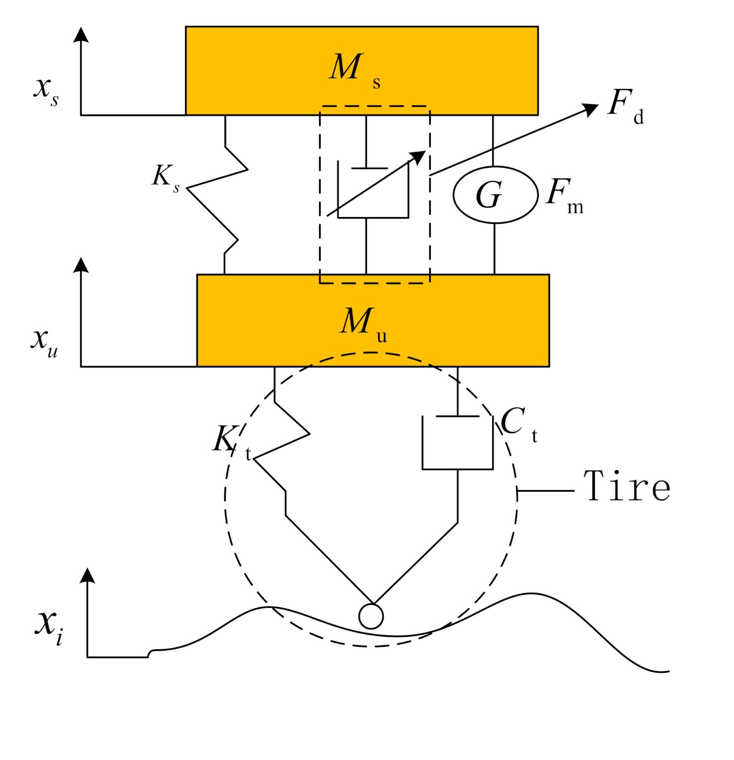
Figure 1 shows the structure diagram of the 1/4 MR regenerative suspension system, mainly composed of carriage, suspension spring, MRD, regenerative motor, and wheels. Wherein, is the sprung mass, is the unsprung mass. is the stiffness coefficient of the suspension spring. is the output damping force of the damper. is the electromagnetic force of the linear motor. is the equivalent stiffness coefficient of the tire. is the tire equivalent damping coefficient. , , and are the displacement of the road, the vertical relative displacement of the carriage, and the vertical relative displacement of the chassis, respectively.
2.1. MR Semi-Active Vehicle Suspension
Assuming that the sprung mass and the unsprung mass are rigid bodies, the motion is only perpendicular to the ground direction. The suspension system has a linear stiffness coefficient and the damping coefficient. The effective stroke of the damper and the linear motor is not exceeded in the process of motion. Furthermore, the dynamic model of the regenerative suspension system shown in Equation (1) is established.
The output damping force of MRD selects the modified Bouc–Wen phenomenon model [11], of which driving current modulation is separated from the hysteresis operator.
where is the drive current. is the drive current modulation function. is the Bouc–Wen hysteresis operator. is the internal piston displacement of the Bouc–Wen model. is the current saturation adjustment parameter, and is the initial displacement. z is a unitless progressive variable,,,,,,,,, are constants of model parameters.
The improved skyhook semi-active controller is applied. Namely, when the acceleration of vehicle sprung mass is inconsistent with the relative velocity of damper, the MRD output damping force is increased. On the contrary, the MRD output damping force is reduced to suppress the resonance amplitude of sprung mass. The MRD semi-active control current is as follows.
where is the ceiling control coefficient.
2.2. Design of Regenerative TPMLM
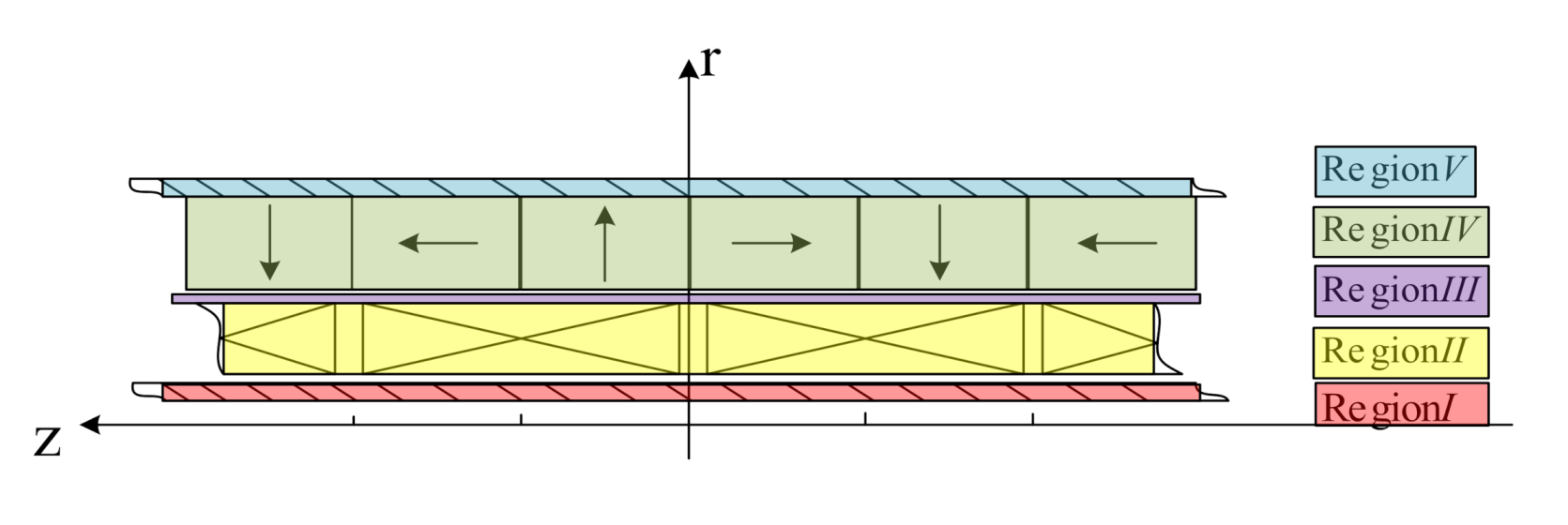
Moving-coil type TPMLM is selected in this paper. Compared with the same size moving-magnetic one, it has a higher energy density, the smaller mass of moving magnetic parts, and higher electromechanical conversion efficiency. The structure diagram is shown in Figure 2, which is divided into I-V according to the material medium. The five areas are core area, winding area, air gap area, permanent magnet area, and back iron area. The magnetic tile adopts the Halbach magnetization arrangement method. This method has the highest average magnetic field energy density. The axial magnetic field distribution accounts for a high proportion of the fundamental wave component, thus reducing the electromagnetic conversion output harmonic content [12].
The regenerative suspension mainly uses TPMLM to recover electric energy. The power can be stored or used directly after conversion. The side effect can be ignored in the analysis. The principle and equation of the rotating motor are directly applied to calculate and design the linear motor and perform park transformation. Turn the motor model from stationary coordinate system to a rotating coordinate system.
In coordinate system, the induced electromotive force is as follows.
where and are the components of stator and coordinate axis. and are the and coordinate axis components of stator current. is stator resistance. and are stator flux linkage.
The flux linkage equation in the coordinate system is as follows.
where is the stator inductance, is the flux linkage of the permanent magnet poles.
The motion equation of the mover is as follows.
where is the mass of the mover. is the electromagnetic force on the mover. is the suspension pressure of the vehicle on the mover, and B is the mechanical damping coefficient.
The expression of is as follows.
where is the number of pole pairs.
3. Establishment of a Joint Simulation Platform
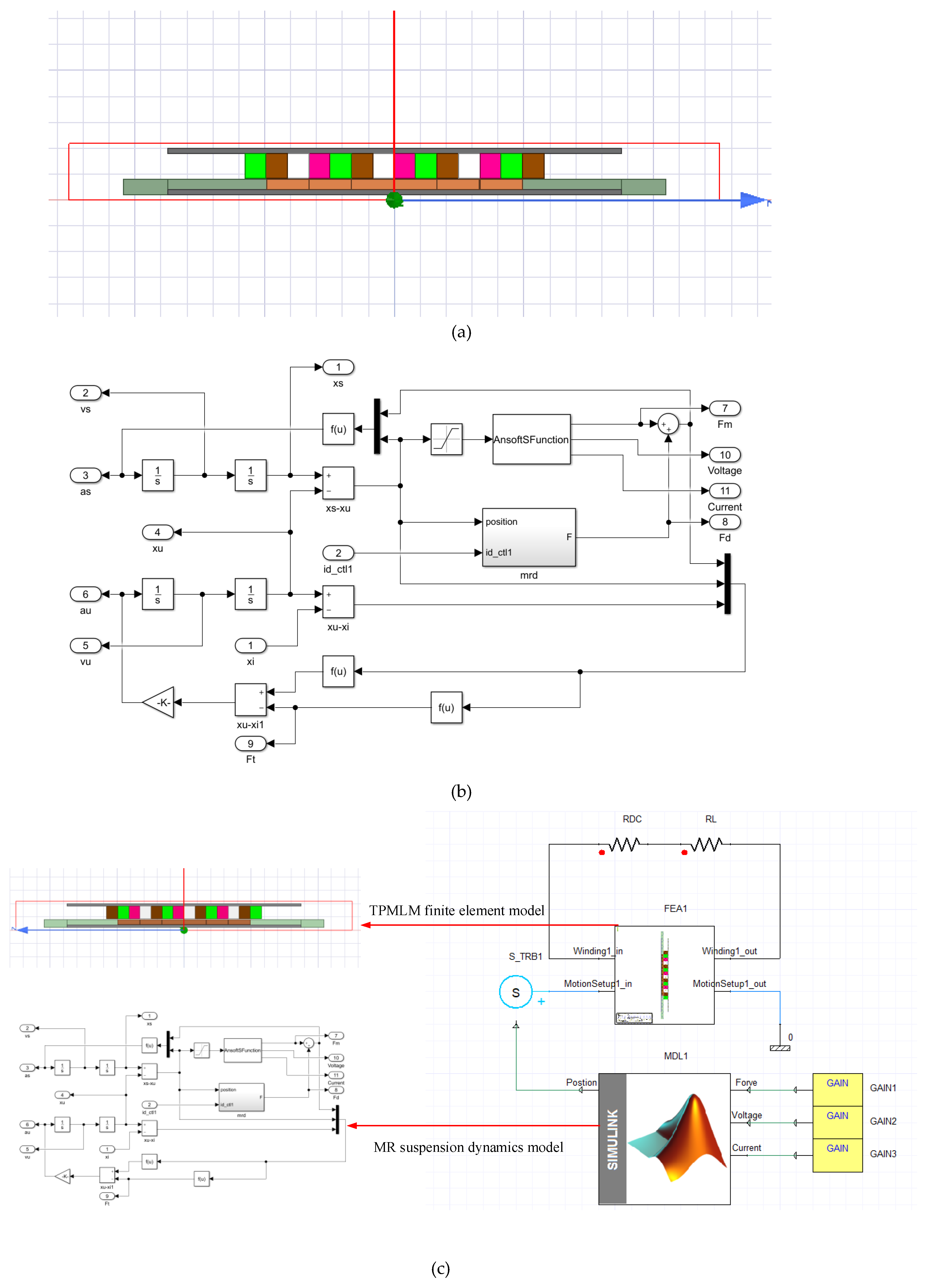
The TPMLM finite element model is established in Ansys/Maxwell, and the vehicle MR semi-active suspension system dynamics model is established in Matlab/Simulink to build the joint operation on the Simplorer platform. Figure 3 is the schematic diagram of the simulation platform.
In Maxwell 2D simulation, the solving domain boundary conditions are set as balloon boundary. The left boundary of the iron core and the right boundary of back iron are set as vector potential boundaries. A winding is set, and six coils are added to it. The moving type in motion setup is set to the positive z-axis direction. The simulation time is from 0 to 1 s, and the time step size is 1 ms. The permanent magnet material uses NdFeB30.
By running the MR suspension dynamic model in Matlab/Simulink under different road conditions , a displacement is obtained, which is the output of the position interface in Figure 3c. Meanwhile, is input to excite the finite element model of the TPMLM through the Simplorer (here named S_TRB1) module. Then, the joint simulation is implanted. After that, the comprehensive performance analysis of the vehicle MR regenerative suspension system is carried out based on the data obtained by the joint simulation.
The TPMLM structure parameters used in the simulation are shown in Table 1. are the radius of the cross-sectional circle of each area of the motor model from the inside to the outside. are the relative permeability of the material in area I-V, and is the permanent magnet pole pitch. is the permanent magnet remanence. is the number of winding slots. is the number of winding turns. is the winding full-slot ratio. is the winding direct current resistance. is the winding wire conductivity. is the winding single-slot cut area. MRD is the actual identification parameter; k0 = 185.954, k1 = 2750.7, k2 = 9.991, = 7.601, I0 = 0.0683, α = 19970, β = 179900, γ = 8901.5, = 1367.4, = 6204.1, n = 2, A = 24.518, = −0.004.
4. Comprehensive Performance Analysis of Regenerative Suspension
4.1. Suspension Performance
Firstly, the frequency response of the MR regenerative suspension system is analyzed. For nonlinear systems, constant amplitude harmonic excitation will cause a large acceleration excitation signal at high frequencies and saturation of suspension components. Therefore, the segmented harmonic excitation signal shown in Equation (11) is used to meet the requirement of limiting the amplitude of the displacement harmonic signal at high frequencies.
where is the single-frequency harmonic amplitude. is the turning frequency. The natural frequency band of the car body and wheels is covered, setting , .
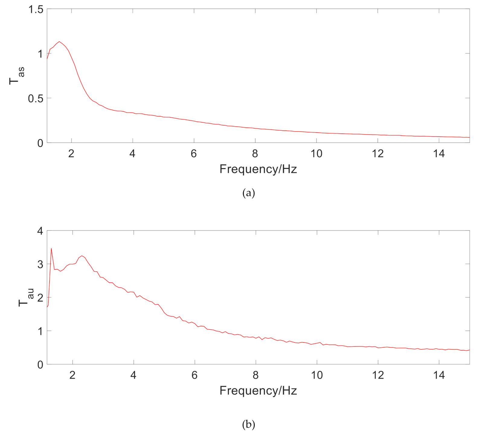
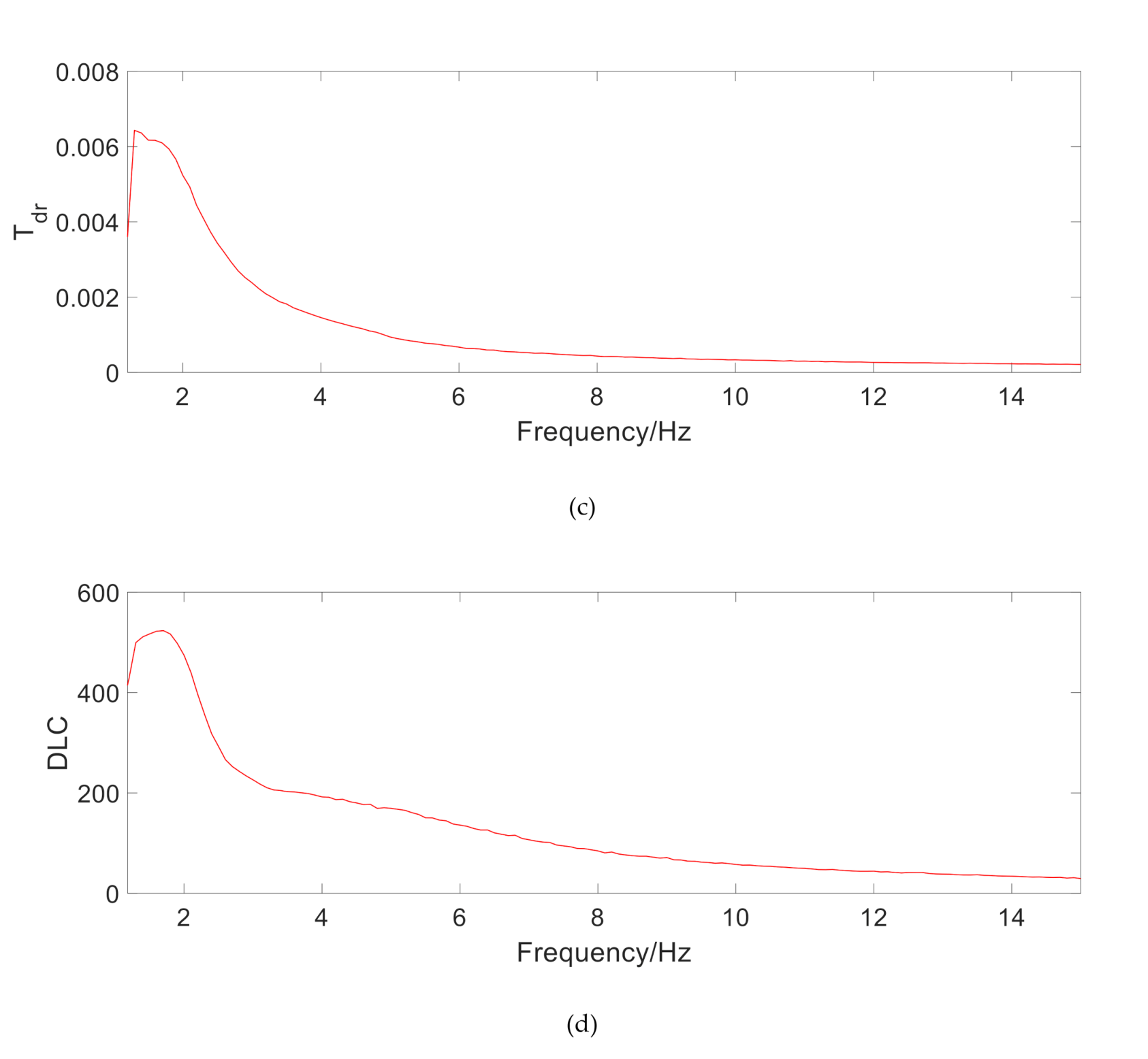
Using the system frequency domain response about sprung mass acceleration transmission rate Tas, unsprung mass acceleration transmission rate Tau, suspension dynamic travel transmission rate Tdr, and tire’s dynamic load coefficient (DLC), the overall suspension performance of vehicle suspension ride comfort and operational stability is evaluated, including resonance suppression, vibration isolation, suspension travel limit, and tire grip [11]. It can be seen from Figure 4 that the first resonance point of Tas is 1.5 Hz, which meets the requirements of passenger car stability. Tau is slightly distorted due to simulation reasons. Both Tdr and DLC show that the TPMLM does not significantly change the handling performance of MR suspension.
Vehicles often encounter various impact roads during driving, which is a short time and high intensity. The smooth pulse signal excitation shown in Equation (12) is used [14].
In the equation, is the amplitude of the smooth pulse signal, is the fundamental frequency, and is the pulse stiffness coefficient. A larger value will cause the excitation to produce larger shock and acceleration signals.
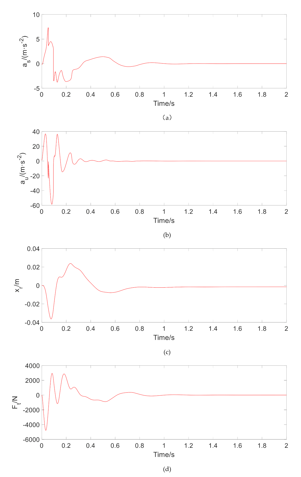
Figure 5 shows the time-domain transient response of , , , and under smooth pulse excitation. The stabilization time of each response adjustment of the system is within 1 s. Due to the addition of TPMLM, small-scale oscillations appear in the initial stage of impulsive excitation, especially the sprung mass acceleration , but the response amplitude does not increase significantly.
The random road is established based on the filtered white noise method, which is used to simulate the wheel excitation input when the vehicle is running on the actual road and gives a general analysis of the performance of the suspension system. The differential equation of road roughness is
where is the function of road roughness. is the Gaussian white noise signal with power spectral density (PSD) of 1. is the cutoff frequency of the road spatial frequency, , is the reference spatial frequency of the road. . is the PSD of the road under the reference spatial frequency , related to pavement classification and speed in steady-state. This experiment selects , .
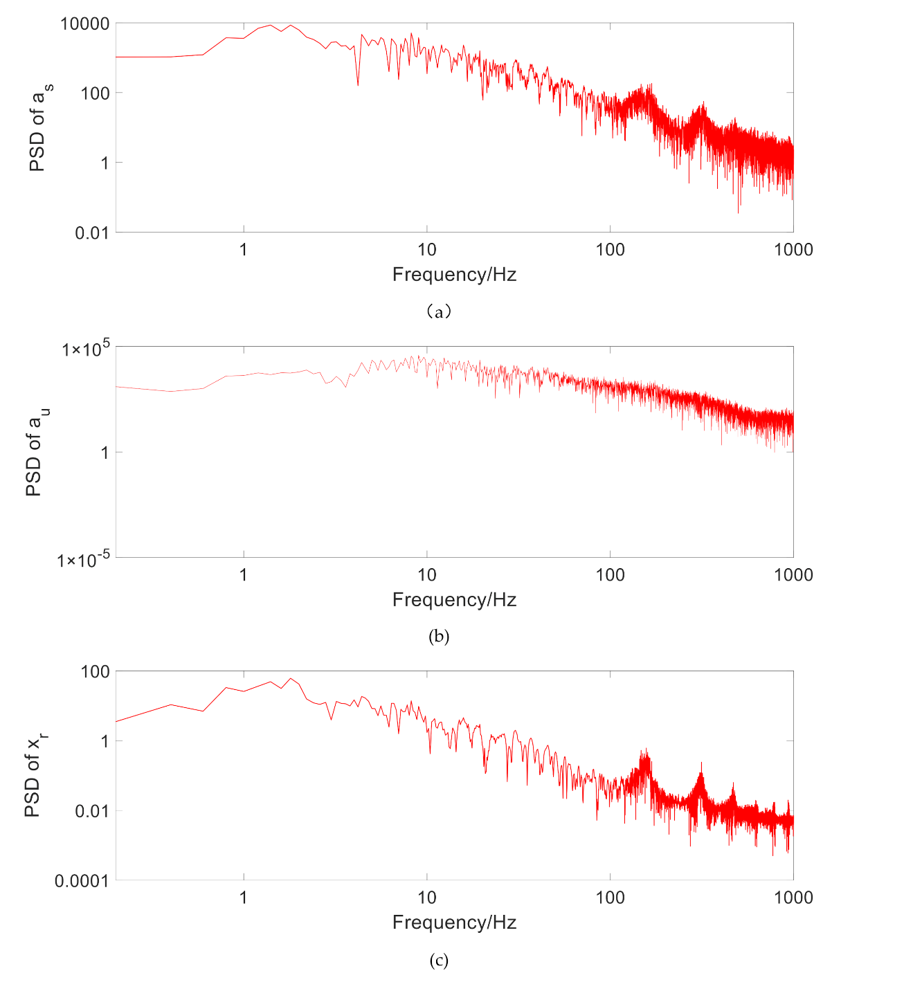
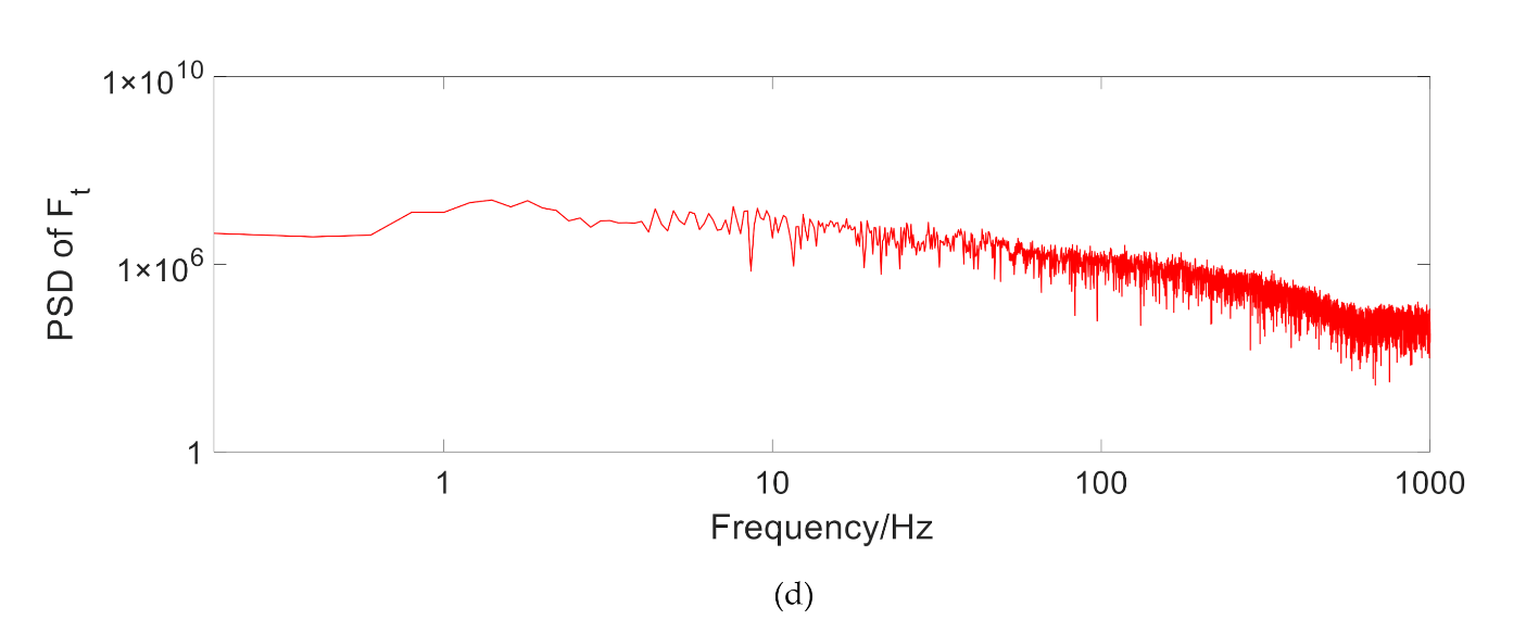
Figure 6 shows , and under random road excitation. It can be seen that the first resonance point of the MR regenerative suspension system is 1.5 Hz, and the second resonance point is about 9.5 Hz, which is consistent with the transmission rate under the above variable amplitude harmonic excitation. It is also indicated that the addition of TPMLM does not significantly change the system stability.
4.2. Regenerative Characteristics
Under the single-frequency harmonic road excitation in Equation (14), above smooth road excitation, and random road excitation, the output regeneration characteristics are observed. The average output power and the effective power value P are employed as the evaluation indicators, as shown in Equations (15) and (16).
where is excitation amplitude, is frequency. The typical frequencies observed here are 1.5 Hz near the resonant frequency of the sprung mass, 6 Hz at the intermediate frequency, and 15 Hz near the resonant frequency of the unsprung mass.
The average output power of the regenerative motor
Power effective value
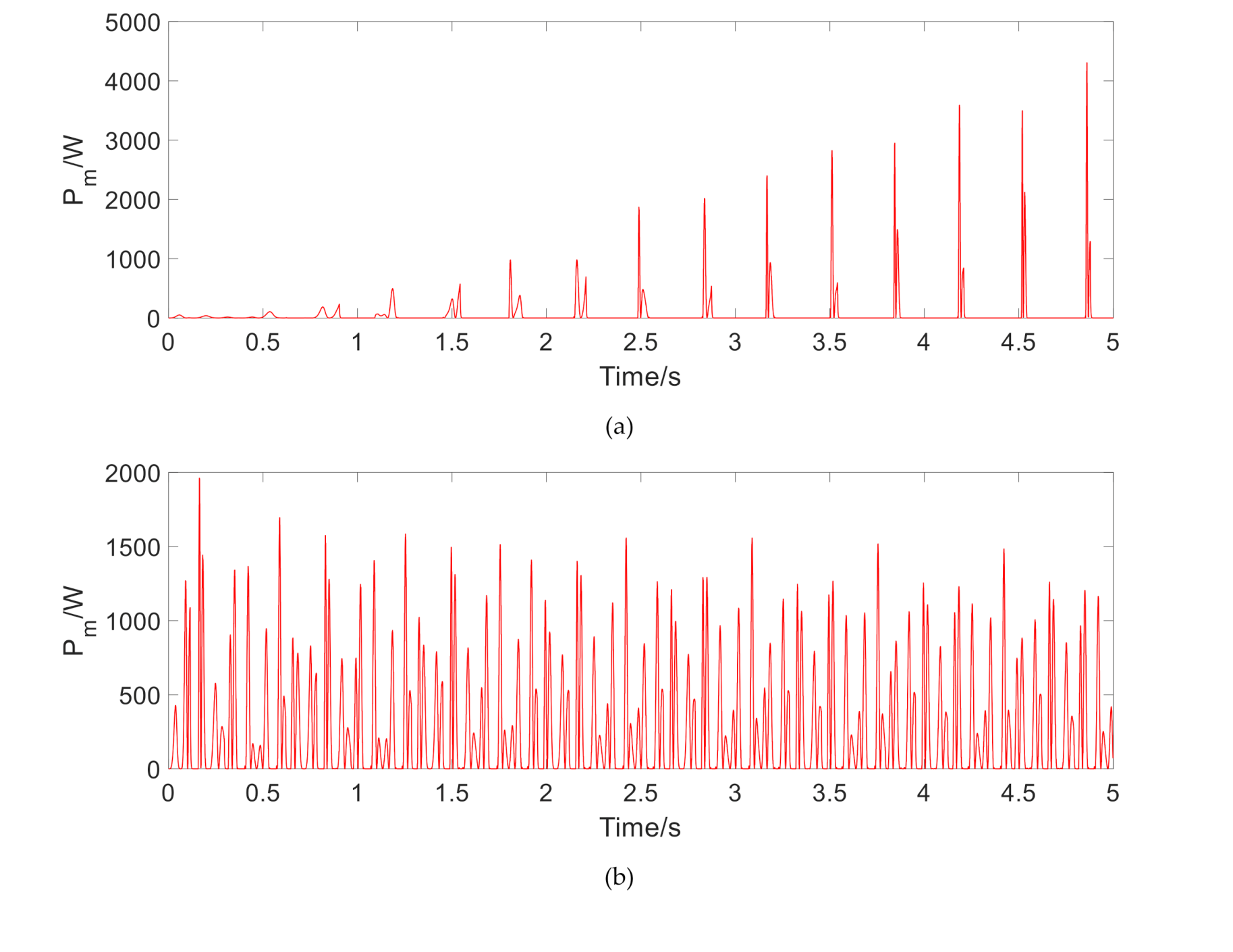
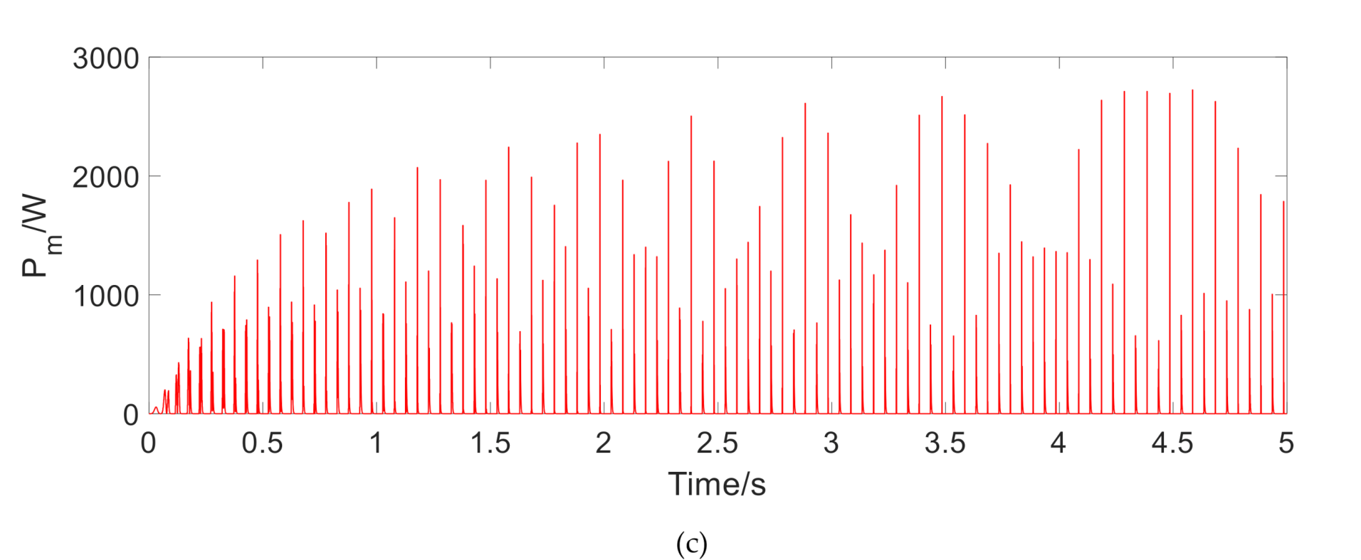
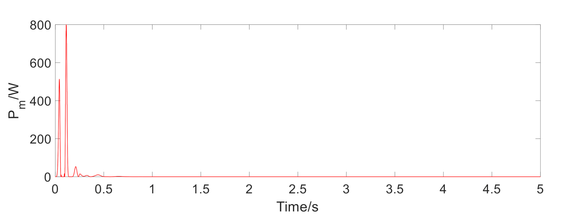
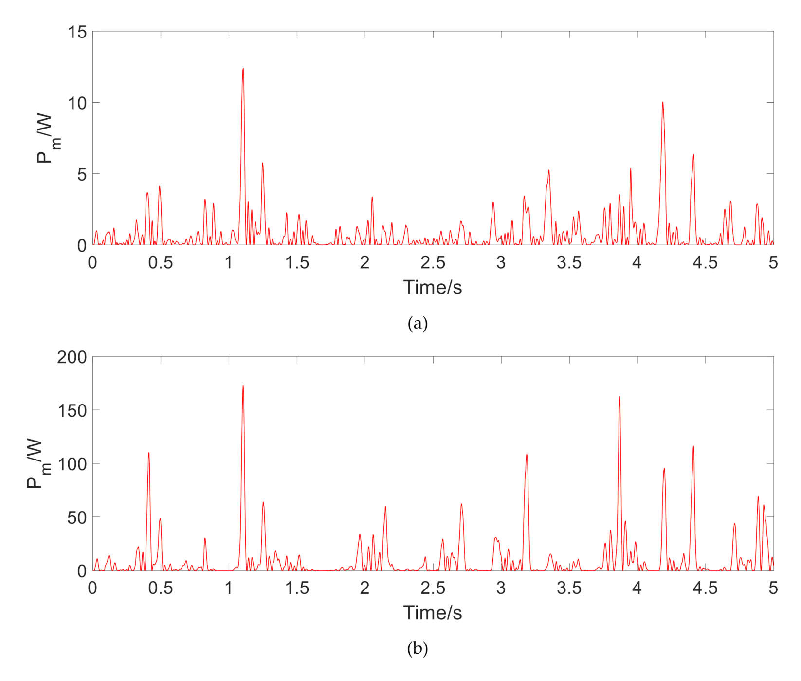
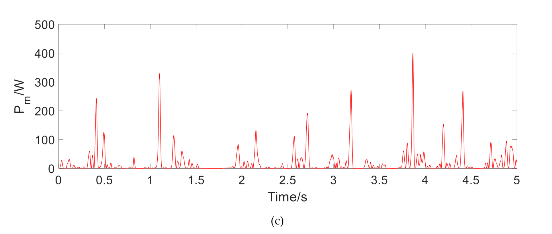
The instantaneous output power is shown in Figure 7, Figure 8 and Figure 9. Table 2 lists the corresponding average output power and power effective value. It can be seen that the effective value of the output power at 1.5 Hz under harmonic excitation reaches about 500 W. As the frequency is increased, the regenerated power is greatly increased. On the impact road, the regenerative time is very short, but the effective value of output power is also about 50 W. On a general road, the recovered power is only 1.5 W on a flat A-class road. With the increase of road unevenness, the output power increases observably, which reaches about 46 W on a C-class road. The above results show that under the excitation of typical frequency harmonics, the MR regenerative suspension has a considerable performance of power regeneration.
5. Conclusions
(1) For the MR regenerative suspension system in parallel with TPMLM, a stability analysis method based on the comprehensive suspension performance under different road excitation is proposed, especially observing whether the resonance point shifts after installing TPMLM;
(2) Dynamic model of the MR suspension system and a finite element model of TPMLM are established, respectively. Matlab/Simulink and Ansys software are used for joint simulation to obtain the comprehensive suspension performance and regenerative characteristics under the road excitation of harmonic, impact, and random pavement.
(3) The simulation results show that the MR regenerative suspension system with improved skyhook control meets the requirements of the natural resonance frequency of the vehicle suspension and effectively improves the driving comfort. At the same time, it has considerable regeneration power.
Author Contributions
Conceptualization, J.H. and H.Z.; methodology, J.H. and E.W.; software, J.H.; formal analysis, J.H. and H.Z.; writing—original draft preparation, J.H.; writing—review and editing, E.W. and H.Z.; All authors have read and agreed to the published version of the manuscript.
Funding
This research received no external funding.
Conflicts of Interest
The authors declare no conflict of interest.
References
- Where the Energy Goes: Gasoline Vehicles. Available online: https://www.fueleconomy.gov/FEG/atv.shtml (accessed on 6 May 2019).
- Karnopp, D. Power requirements for traversing uneven roadways. Veh. Syst. Dyn. 1978, 7, 135–152. [Google Scholar] [CrossRef]
- Browne, A.L.; Hamburg, J.A. On-road measurement of the energy dissipated in automotive shock absorbers. In Symposium on Simulation and Control of Ground Vehicles and Transportation Systems; American Society of Mechanical Engineers: New York, NY, USA, 1986; Volume 80, pp. 1–10. [Google Scholar]
- Huang, K.; Zhang, Y.C.; Yu, F. Coordinated optimization of comprehensive performance of electric active energy feedback suspension. J. Shanghai Jiaotong Uni. 2009, 43, 226–230. [Google Scholar]
- Yu, F.; Zhang, Y.C. Active suspension technology of energy feedback vehicle. Trans. Chin. Soc. Agric. Mach. 2010, 41, 1–6. [Google Scholar]
- Dong, X.M.; Peng, S.J.; Yu, J.Q. Study on characteristics of self powered vehicle magnetorheological damper. J. Mech. Eng. 2016, 52, 83–91. [Google Scholar] [CrossRef]
- Kou, F.R.; Liang, J.; Wei, D.D. Research on a parallel semi-active suspension actuator. China Mech. Eng. 2017, 28, 2318–2324. [Google Scholar]
- Zhu, Z.Y.; Zheng, L.; Wang, K. Energy feedback characteristics and experimental study of self powered rheological damper. In Proceedings of the 2014 Annual Meeting of China Society of Automotive Engineering, Shanghai, China, 22 October 2014; pp. 1210–1216. [Google Scholar]
- Kou, F.R.; Chen, L.; Zhang, W. Study on characteristics of self powered magnetorheological semi-active suspension. Hydraul. Pneum. 2016, 11, 10–14. [Google Scholar]
- Lv, X.Y.; Ji, Y.J.; Zhao, H.Y.; Zhang, J.; Zhang, G.; Zhang, L. Research Review of a Vehicle Energy-Regenerative Suspension System. Energies 2020, 13, 441. [Google Scholar] [CrossRef] [Green Version]
- Zhang, H.L.; Wang, E.R.; Min, F.H.; Subash, R.; Su, C. Skyhook-based Semi-active Control of Full-vehicle Suspension with Magneto-rheological Dampers. Chin. J. Mech. Eng. 2013, 26, 498–505. [Google Scholar] [CrossRef]
- Zhu, Z.Q.; Howe, D. Halbach Permanent Magnet Machines and Applications: A Review. IEE Proc. Electr. Power Appl. 2001, 148, 299–308. [Google Scholar] [CrossRef]
- Lu, D.S.; Zhang, H.L.; Liu, J.; Wang, E. Structural Parameter Optimization of a Tubular Permanent-Magnet Linear Machine for Regenerative Suspension. Shock Vib. 2019, 2019, 11. [Google Scholar] [CrossRef] [Green Version]
- Young, K.D.; Utkin, V.I.; Ozguner, U. A control engineer’s guide to sliding mode control. IEEE Trans. Control Syst. Technol. 1999, 7, 328–342. [Google Scholar] [CrossRef] [Green Version]
Figure 1.
The structure of the 1/4 magnetorheological (MR) regenerative suspension system. The explanations of , are listed in the main-text.
Figure 1.
The structure of the 1/4 magnetorheological (MR) regenerative suspension system. The explanations of , are listed in the main-text.

Figure 2.
Structure of moving-coil tubular permanent magnet linear motor (TPMLM).

Figure 3.
Schematic diagram of the MR regenerative suspension system simulation platform. (a) A finite element simulation model, (b) Suspension dynamics simulation model, (c) Joint simulation model.
Figure 3.
Schematic diagram of the MR regenerative suspension system simulation platform. (a) A finite element simulation model, (b) Suspension dynamics simulation model, (c) Joint simulation model.

Figure 4.
The frequency response of MR regenerative suspension. (a) Transmission rate of the sprung mass acceleration, (b) Transmission rate of the unsprung mass acceleration, (c) Transmission rate of the suspension dynamic travel, (d) Dynamic load coefficient of the tire.
Figure 4.
The frequency response of MR regenerative suspension. (a) Transmission rate of the sprung mass acceleration, (b) Transmission rate of the unsprung mass acceleration, (c) Transmission rate of the suspension dynamic travel, (d) Dynamic load coefficient of the tire.


Figure 5.
Dynamic characteristics under smooth pulse excitation. (a) Sprung mass acceleration under smooth pulse, (b) Free spring-mass acceleration under smooth pulse, (c) Suspension dynamic travel under smooth pulse, (d) Tire dynamic force under smooth pulse.
Figure 5.
Dynamic characteristics under smooth pulse excitation. (a) Sprung mass acceleration under smooth pulse, (b) Free spring-mass acceleration under smooth pulse, (c) Suspension dynamic travel under smooth pulse, (d) Tire dynamic force under smooth pulse.

Figure 6.
Power spectral density (PSD) under random road excitation. (a) PSD of the sprung mass acceleration, (b) PSD of the unsprung mass acceleration, (c) PSD of the suspension dynamic stroke, (d) PSD of the tire dynamic force.
Figure 6.
Power spectral density (PSD) under random road excitation. (a) PSD of the sprung mass acceleration, (b) PSD of the unsprung mass acceleration, (c) PSD of the suspension dynamic stroke, (d) PSD of the tire dynamic force.


Figure 7.
The instantaneous output power of regenerative motor under sinusoidal excitation. (a) Output power at 1.5 Hz, (b) Output power at 6 Hz, (c) Output power at 10 Hz.
Figure 7.
The instantaneous output power of regenerative motor under sinusoidal excitation. (a) Output power at 1.5 Hz, (b) Output power at 6 Hz, (c) Output power at 10 Hz.


Figure 8.
The instantaneous output power of regenerative motor under a smooth pulse.

Figure 9.
The instantaneous output power of regenerative motor under the random road. (a) Output power under A-class road, (b) Output power under B-class road, (c) Output power under C-class road.
Figure 9.
The instantaneous output power of regenerative motor under the random road. (a) Output power under A-class road, (b) Output power under B-class road, (c) Output power under C-class road.


Table 1.
Data parameters of 1/4 magnetorheological (MR) regenerative suspension [13].
Table 1.
Data parameters of 1/4 magnetorheological (MR) regenerative suspension [13].
| Structural Parameters | Value | Unit | |
|---|---|---|---|
| Cross-sectional radius | 4 | mm | |
| RI | 8 | ||
| RII | 16 | ||
| RIII | 17 | ||
| RIV | 36 | ||
| RV | 40 | ||
| Relative permeability | μrI | 400 | H/m |
| μrII | 1 | ||
| μrIII | 1 | ||
| μrIV | 1.02 | ||
| μrV | 400 | ||
| Permanent magnet polar distance | 33 | mm | |
| Permanent magnet remanence | 1.23 | T | |
| Winding slots number | 6 | ||
| Winding turns number | 100 | ||
| Winding full slot rate | 0.9 | ||
| Winding direct current resistance | 0.42 | ||
| The conductivity of the winding wire | 17.5 | nS/m | |
| Winding single slot cross-sectional area | 264 | ||
| Regenerative suspension parameters | 562.5 | Kg | |
| 90 | Kg | ||
| 57,000 | N/m | ||
| 2500 | N/ | ||
| 285,000 | N/m | ||
| 100 | N/ | ||
Table 2.
The average and effective output power of the regenerative motor.
| Types of Road Excitation | ||||
|---|---|---|---|---|
| Sinusoidal | Frequency (Hz) | |||
| 1.5 | 142.2825 | 497.2003 | ||
| 6 | 308.8829 | 493.1127 | ||
| 15 | 389.2749 | 771.0291 | ||
| Smooth pulse | 5.8977 | 52.2608 | ||
| Random road | Road class | |||
| A | 0.7540 | 1.4778 | ||
| B | 9.7138 | 22.2265 | ||
| C | 18.6516 | 46.0925 |
Publisher’s Note: MDPI stays neutral with regard to jurisdictional claims in published maps and institutional affiliations. |
© 2020 by the authors. Licensee MDPI, Basel, Switzerland. This article is an open access article distributed under the terms and conditions of the Creative Commons Attribution (CC BY) license (http://creativecommons.org/licenses/by/4.0/).
Share and Cite
MDPI and ACS Style
Huang, J.; Wang, E.; Zhang, H. Analysis and Research on the Comprehensive Performance of Vehicle Magnetorheological Regenerative Suspension. Vehicles 2020, 2, 576-588. https://0-doi-org.brum.beds.ac.uk/10.3390/vehicles2040033
AMA Style
Huang J, Wang E, Zhang H. Analysis and Research on the Comprehensive Performance of Vehicle Magnetorheological Regenerative Suspension. Vehicles. 2020; 2(4):576-588. https://0-doi-org.brum.beds.ac.uk/10.3390/vehicles2040033
Chicago/Turabian StyleHuang, Jinhui, Enrong Wang, and Hailong Zhang. 2020. "Analysis and Research on the Comprehensive Performance of Vehicle Magnetorheological Regenerative Suspension" Vehicles 2, no. 4: 576-588. https://0-doi-org.brum.beds.ac.uk/10.3390/vehicles2040033