1. Introduction
A vehicle’s interior sound gains more importance since the vehicle electrification and the resulting loss of the combustion engine lead to an increasing relevance of road noise [
1,
2]. Road noise can be divided into different phenomena. One of them is called booming noise. It occurs in both conventional fuel-powered and electric vehicles. For fuel-powered vehicles it is either caused by the vehicle’s powertrain or through road excitation [
3]. Due to the increasing importance of road noise [
2,
4] and the vehicle electrification in general, this article only considers road excited booming noise, which is transmitted in the vehicle as follows.
Non-uniform road profiles excite the axles of a vehicle and cause vibrations in the front and rear axle at low frequencies [
3,
5]. The structure-borne noise is transmitted to the vehicle body and leads to an airborne noise in the cavity [
6,
7]. The front passengers perceive the noise as booming, so-called road booming noise, below 100 Hz [
3,
8]. Previous studies show that the rear axle is the primary transmission path for road excitation of the booming phenomenon [
9,
10]. Phase excitation and anti-phase excitation of the axle can be considered separately and independently of each other [
10]. Furthermore, phase excitation causes the dominant sound pressure level in the vehicle interior at low frequencies below 60 Hz [
10]. Therefore, this work will focus on in-phase excitation of the rear axle and the vehicle body.
To optimize the road booming noise, or booming noise in general, recent studies focus primarily on the optimization of the powertrain, the axles, and its connection to the vehicle’s body. Some of the influencing variables are mainly the tires [
11], the connection points of the powertrain to the body [
12,
13] or the stiffness of the subframe mounts [
13]. The influence of new rear axle components, such as rear axle steering or active roll stabilization on the road booming noise still has to be investigated.
Furthermore, booming noise can be improved by changes to the vehicle’s body, e.g., optimizing the rear tailgate [
14] or de-coupling different structure-acoustic [
15]. However, the influence of various body elements still has to be analyzed.
Our main goal is to build a whole car simulation model and validate all different elements with measurements. We aim to find new different parameters in the model, which control the booming noise sensitivity of the vehicle. To reduce the complexity of the model and to save resources in the validation process, we first need to understand which elements are crucial for describing road booming noise. For this purpose, it is necessary to describe the main transmission paths from excitation to sound pressure in the vehicle interior.
Since the influence of different rear axle components, e.g., the rear axle steering, or various body elements, e.g., the cockpit, on the booming noise transmission paths still has to be investigated, we aim to analyze these components in particular.
This paper shows the importance of different rear axle elements and body elements for describing the booming noise phenomenon based on different measurements. The analyzed elements are rear axle steering (mechanical components), active roll stabilization (mechanical components), forced ventilation openings, front seats, headliner, cockpit, and trim elements.
2. Materials and Methods
In this section, we describe our test vehicle, the used methods and measurement equipment as well as the used test benches.
2.1. Research Vehicle
Since station wagons are more sensitive to road booming noise than sedans [
6], we picked a four-door shooting brake station wagon equipped with all-wheel-drive, a V8 engine, optional rear axle steering and active roll stabilization [
16]. It is shown in
Figure 1 (see
Section 2.2).
2.2. Measurement Equipment and Methods
We mainly used two methods. An impact measurement for determining the noise transfer functions of the vehicle and the vibro-acoustical modal analysis for identifying the coupled modes of the body and the cavity. For each of the two methods, first the used measurement methodology and then the processing of the obtained data is explained.
2.2.1. Determining Noise Transfer Functions of a Vehicle
We analyzed the vehicle in a trimmed body shape. The engine, the powertrain, the exhaust system, the front, and the rear axle are removed. This state is typically used to determine the structural behavior of the vehicle’s body.
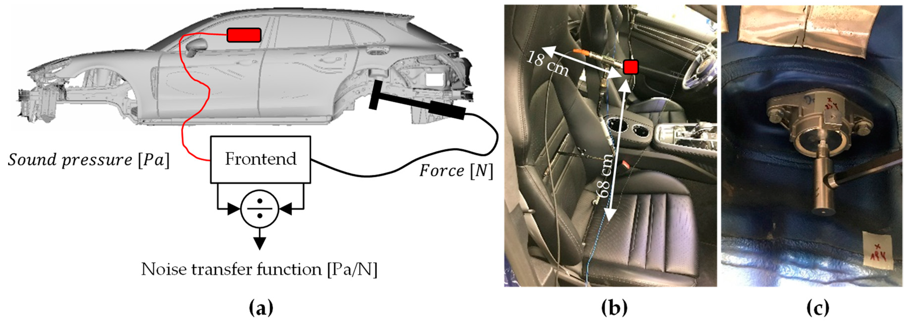
Figure 1 shows the principle of measuring noise transfer functions on a vehicle.
An impact hammer (PCB 086C03) initiates force in one direction on a defined point into the body structure, e.g., the attachment of the rear shock absorber in z-direction (c). Simultaneously, microphones (B&K, Yorba Linda, CA, USA, 4189) at the driver’s and front passenger seat (b) record the resulting noise. A frontend (Simcenter SCADAS Mobile) merges all the measurement signals and sends it to the measurement software, which collects all the obtained data. We then convert the force and the sound pressure into the frequency domain and divide them by each other. The result is the noise transfer function (NTF). We measured the noise transfer function from all connection points between the vehicle body and the connection points of the rear axle in every direction separately to the driver’s ear. The measurement points on the body are two rear shock absorbers, two rear springs and four rear subframe mounts.
2.2.2. Vibro-Acoustical Modal Analysis of a Vehicle
Figure 2 shows the used method for identifying the frequency response functions of the trimmed body with a moving microphone array and accelerometers.
Two omnidirectional point sources excite the vehicle’s cavity. Accelerometers (PCB 356A16) on the vehicle’s body and the rear tailgate pick up the acceleration on the structure, a microphone array (B&K 4189) inside the vehicle records the sound pressure. The time data is transferred to the frequency domain and divided by the point sources volume velocity. The result is the frequency response function (FRF). We moved the microphone array through the vehicle’s cavity and repeated the measurement process. The accelerometers were positioned on the exterior of the vehicle, e.g., the roof, the doors, and the rear tailgate.
We then use the vibro-acoustical modal analysis to extract the coupled modes from the determined frequency response functions. Since the theory of modal analysis is well known, only a short introduction will be given. For the calculation of the acoustic modes, one starts with the second-order coupled equation [
17]:
,
,
are the mass, damping and stiffness matrices for the structural vibration, while
,
,
are for the fluid part and
,
for the coupling submatrices.
and
stands for the acceleration and the force of the structure.
,
and
are the sound pressure, the volume velocity, and the density of the fluid. After applying the theories of vibro-acoustic reciprocity, general modal analysis and partial fraction expansion, one gets the following results [
17]:
is the modal scaling factor and
the number of modes in the frequency band.
are the eigenvectors,
the searched eigenvalue and
the domain of the used Laplace transformation.
is the acoustical excitation with the q-source at location
. The terms on the left side of the equations equal the measured frequency response functions. Using the FRFs, the equations can be solved for the parameter estimation of the coupled modes such as the modal shapes and the modal frequencies. More detailed information about the theory of the vibro-acoustical modal analysis can be found in [
17,
18,
19]. For solving the equations, we used the software Siemens Simcenter Testlab with the PolyMax method [
20].
2.3. Test Benches
For measuring the noise transfer functions and the frequency response functions of the vehicle, its trimmed body is placed on a hoist in an acoustic chamber. Air suspension pads between the body and the hoist decouple the vehicle from the lift.
The rear axle examinations are performed on a chassis identification test bench [
21].
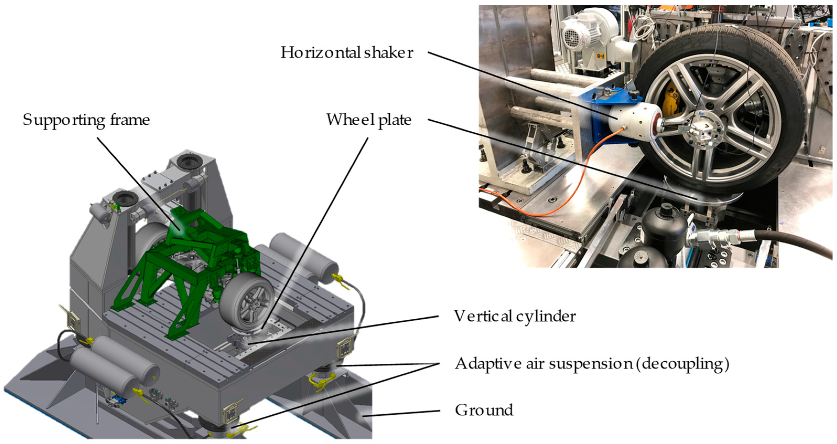
Figure 3 shows the test bench and its components.
The rear axle is attached within its mounts to the supporting test bench frame. The frame itself is resonance free up to a frequency of 129 Hz and fixed to the test bench. An adaptive air suspension decouples the test bench from the ground (25 tons, natural frequency 1.1 Hz). The tires can be excited at both sides by two vertical cylinders and a wheel plate. For horizontal excitation two additional shakers are added to the setup. A bar connects the shaker with the center of the wheel hub. Triaxial accelerometers (PCB 354C03) measure the acceleration of the left and right wheel carrier. Additional accelerometers on the supporting test bench frame ensure that no excitation via the frame caused by the shaker attachment occurs. Load cells (Kistler, Winterthur, Switzerland, 9167A & Kistler 5018, Michigan Scientific Corporation, Charlevoix, MI, USA, Tr3D-C 10K) determine the internal forces between the rear axle and the supporting frame of the test bench.
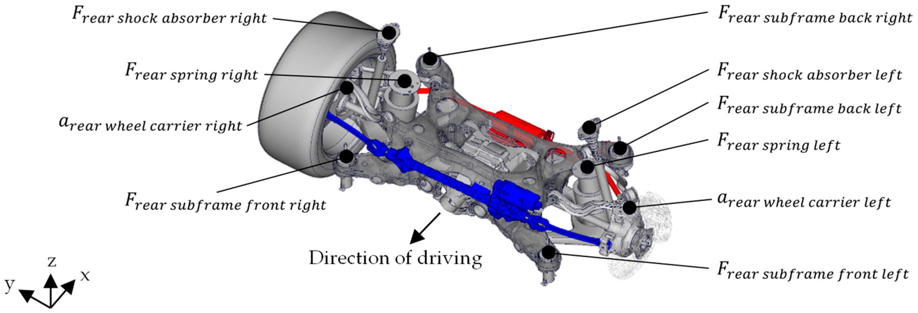
Figure 4 shows the rear axle and the sensor positions.
The internal forces at the four subframe mounting points and the shock absorbers are recorded in three directions, while the force at the spring is recorded in vertical direction. The rear axle steering (mechanical components, blue) can be added without removing the axle from the test bench. The change from the conventional stabilizer to the active roll stabilization (mechanical components, red) can also take place on the test bench without removing the axle.
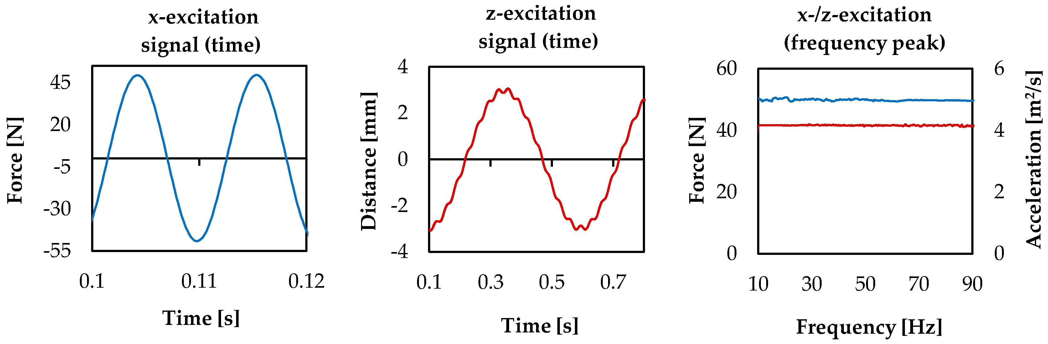
Figure 5 shows the used excitation signals.
The two left charts show the time signals and the right chart the corresponding signals in the frequency domain. For horizontal excitation (blue), only a frequency sweep with constant force could be used. For vertical excitation (red), we used a frequency sweep with a constant acceleration of 4 m/s
2. To ensure a working shock absorber, we overlay the signal with a path constant sinus at 2 Hz. The test bench excites the rear axle at the left and right side in-phase.
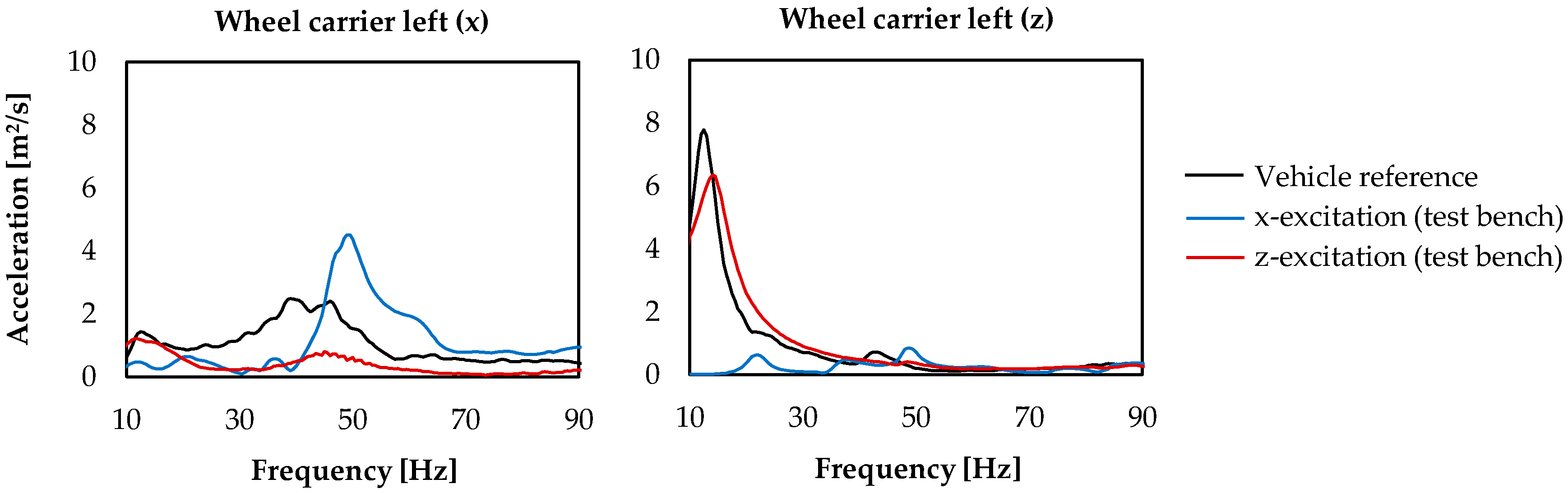
Figure 6 shows the acceleration on the left wheel carrier of the rear axle on the test bench in comparison to a real road excitation in a vehicle.
The black curves show the acceleration on the wheel carrier in a vehicle driven on a road with a non-uniform road profile at 40 km/h. The red and blue curves correspond to the rear axle on the test bench for the two different excitation signals.
For horizontal excitation (blue), the acceleration in x-direction below 40 Hz is lower than the vehicle reference. Above 40 Hz, the x-acceleration on the test bench is higher than the reference. Although the horizontal excitation is not direct comparable to the real excitation of the rear axle on a test track, it is useful to investigate the influences of the different rear axle elements.
For vertical excitation (red), the acceleration in z-direction matches the vehicle reference quite well.
3. Results
In this section, we determine relevant force transmission paths from the rear axle to the test bench at low frequencies. By analyzing the influences of various axle elements on these force paths, we expect to gain a better understanding of which axle elements influence the acoustic comfort at low frequencies. To investigate the trimmed body, we analyze the noise transfer functions (NTFs) for the determined force transmission paths. In addition to this, we use the results of an experimental modal analysis of the vehicle’s cavity to identify which body components excite the cavity. Our purpose is to specify which rear axle and body elements are crucial for describing low frequency noise phenomena, e.g., road booming noise.
3.1. Determining Relevant Rear Axle Forces
At first, we compare the directions of the internal forces between the rear axle and the supporting frame of the test bench for all connection points.
Figure 7 shows the forces at two subframe mounts and the shock absorbers in x-, y- and z-direction, as well as the force at the spring in vertical direction. The excitation signals are applied with constant force in horizontal direction (x) and with constant acceleration in vertical direction (z). Due to the symmetry of the rear axle, only results for the left side of the vehicle are presented.
It is found that in comparison to the x- and z-direction, the y-direction is relatively small. Furthermore, the forces at the shock absorber are only important in z-direction and those at the spring are irrelevant in the shown frequency band. Particularly noteworthy are the peaks at approximately 34 Hz (I) at the forces in z-direction, 39 Hz (II) at the forces in x-direction and 45 Hz (III) at both directions. It can be seen that the peaks at 34 Hz (I) and 39 Hz (II) are equally noticeable at both the front and rear subframe mounts and have similar magnitudes. In contrast, the third peak at 45 Hz (III) in the z-forces is only distinct at the rear subframe mounts.
Since the excitation signal in z-direction differs from the x-direction, the resulting forces for the two excitation directions cannot be properly compared. Nevertheless, the measured forces for the z-excitation are lower than the forces with x-excitation and decrease above frequency. However, this does not mean that the rear axle is more sensitive to excitation in x-direction than in z-direction. The results concerning the relevant force paths are very similar to those with horizontal excitation. The forces at the shock absorber are only relevant in z-direction, while the forces at the spring are irrelevant. Furthermore, all forces in y-direction are relatively small. It is found that excitation in z-direction causes mainly resulting forces in z-direction. The peak at 34 Hz (IV) is especially notable. It is also primarily distinct in z-direction. Similar to the excitation of the rear axis in x-direction, the peak is equally noticeable for the front and rear subframe mounts.
In conclusion, the following paths are identified as relevant for further investigation: all four subframe mounts in x- and z-direction as well as the shock absorber in z-direction. In addition, three areas around approximately 34 Hz (I), 39 Hz (II) and 45 Hz (III, IV) are found to be of special relevance. The paths of the four subframe mounts in x- and z-direction are mainly important for these three frequencies.
3.2. Influence of Rear Axle Elements on Relevant Rear Axle Forces
In the next step, we changed the configuration of the rear axle on the test bench and repeated the test with both excitation directions. In the first step, we analyzed the initial condition without rear steering and without roll stabilization. Second the rear axle steering and finally the active roll bar is successively applied. To see the influences of the two additional axle elements separately, we compared each axle configuration with its previous state as a reference. The result is shown in
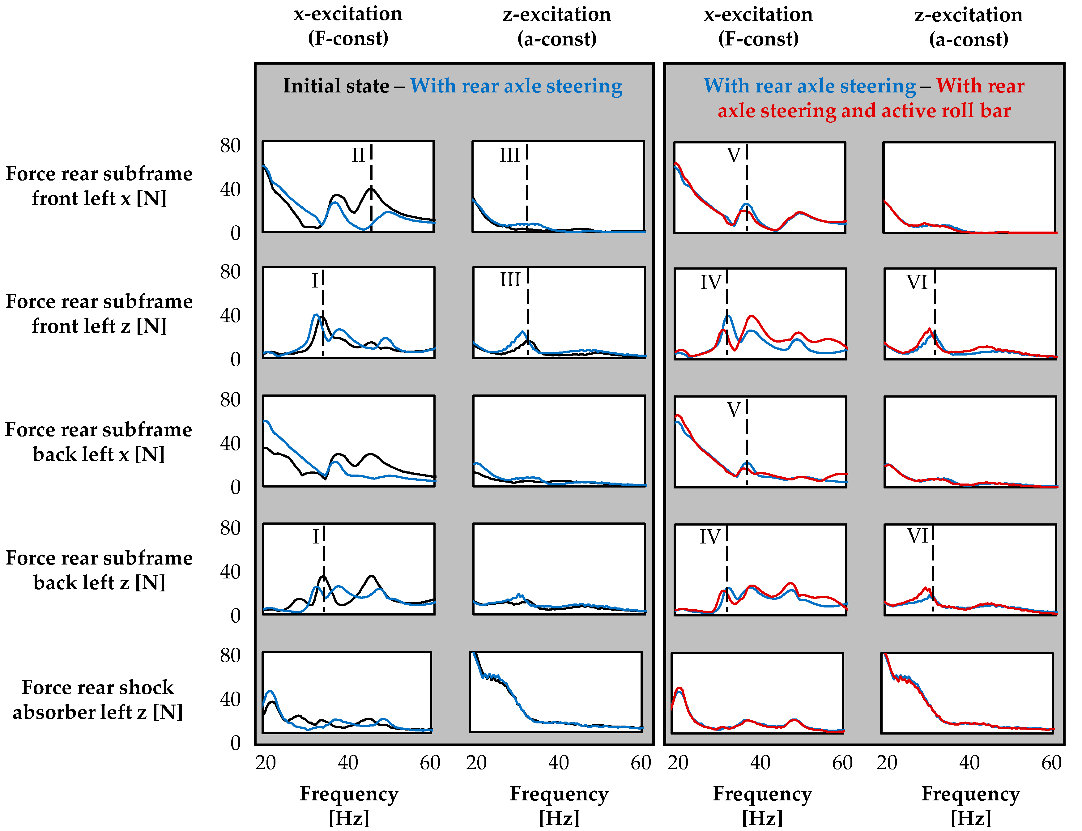
Figure 8.
The left two columns show the result for the rear axle steering, the right two columns for the active roll bar. The five rows show the forces at the relevant points, which were identified in
Section 3.1. The black curves display the initial state of the axle. The blue curves show the influence of the rear axle steering and the red curves of the active roll bar. Since we changed the configuration of the axel successively, each axle element is compared to the axle’s previous state.
In the first column, it is clearly notable that the rear axle steering influences the forces especially at the four subframe mounts. The steering gear adds approximately 10 kg mass to the front part of the rear axle subframe. Due to this increase, a shift of the peaks from 33 Hz to 32 Hz and 39 Hz to 38 Hz is obvious. It is noteworthy that the amplitude at 33 Hz (I) increases at the front mount in z-direction by +7% and decreases at the back mount in z-direction by −27%. Furthermore, the rear axle steering has a positive effect on the amplitude of the peak at 45 Hz (II). It drastically decreases the maximum force especially in x-direction, up to −54% at the rear subframe front left (x). The forces at z-excitation in the second column show very similar results. Due to the different excitation signals; however, the effects at higher frequencies are less visible. The steering increases the forces at the subframe mounts in x-direction up to +130% (rear subframe front left x at 33 Hz, III). The amplitude of the peak at 33 Hz (III) in z-direction increases by +63% and shifts to 32 Hz. In comparison, the effects at the rear axle shock absorber are very small.
The third column shows the influence of the active roll stabilization on the rear axle forces for excitation in x-direction. The active roll bar adds about seven more kilograms to the rear of the subframe compared to a conventional anti-roll bar. Due this increase, the peak at 33 Hz (IV) shifts again to 32 Hz and its amplitude decreases at all subframe mounts in z-direction, up to −30% at the rear subframe front left z position. The addition of an active roll bar reduces the amplitude of the peak at 39 Hz (V) at the front and rear subframe mounts in the x-direction by up to −24% (rear subframe front left x), but increases the forces in z-direction by up to +51% (rear subframe front left z). The effects described for excitation in x-direction differ slightly from excitation in z-direction. The active roll bar has almost no influence on the forces on the subframe mounts in x-direction and on the shock absorber. However, the peak at 33 Hz (VI) shifts to 32 Hz and its amplitude increases at the subframe mounts in z-direction by up to +19% (rear subframe front left z).
In summary, it is found that both the rear axle steering and the active roll stabilization considerably influence the forces transmitted by the rear axle, mainly the forces of the subframe mounts. Since the rear axle elements cause opposite effects on the amplitude depending on the excitation direction of the axle, it cannot be clearly determined whether the elements have a positive or negative influence on road booming noise based on the performed test bench investigation. However, it can be stated that these rear axle elements are important for the description of road booming noise.
3.3. Influence of Vehicle Body Elements on the Noise Transfer Functions of a Trimmed Body
For the investigation of the trimmed body, we analyzed all noise transfer functions from the rear axle connection points to the driver’s position (see
Section 2.2 and
Section 2.3). Since only the four subframe mounts in x- and z-direction as well as the shock absorber in z-direction are relevant paths for transmitted forces from the axle to the trimmed body (see
Section 3.1), we only investigate these points. At first, we measured the complete trimmed body as reference and then successively removed body elements and repeat the measurement for each state.
After the reference state, we closed all forced ventilation gaps of the trimmed body structure. Then we removed the driver’s seat and the front right seat. After that we removed the headliner. Thereupon we detached the full cockpit module. In the last state, we removed the remaining trim elements such as the door panels, the tailgate cover, or the bottom panels.
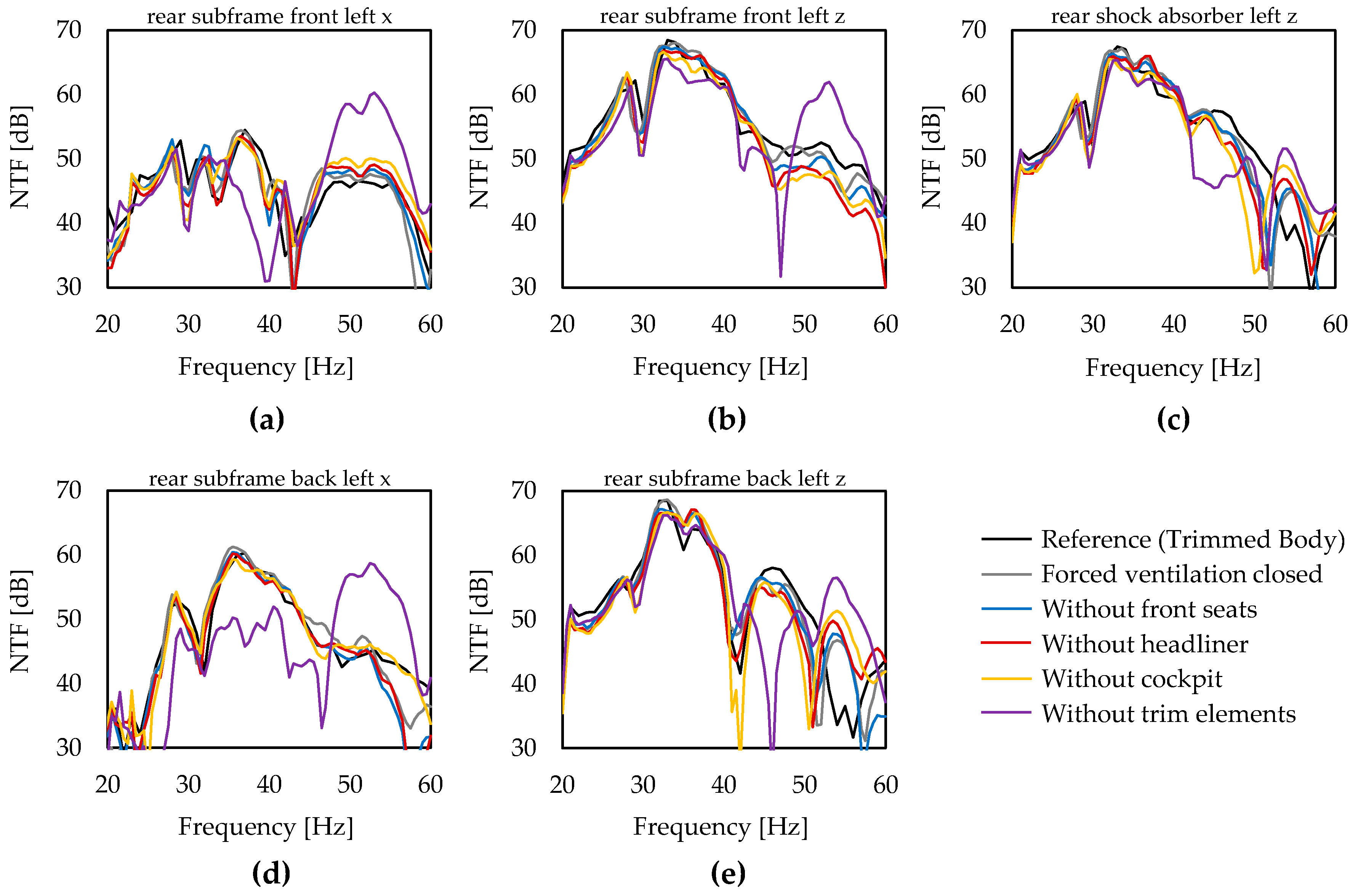
Figure 9 shows all measured noise transfer functions for each state from the relevant rear axle connection points to the driver’s position.
The noise transfer functions of the trimmed body are relatively similar from all three relevant axle connection points in z-direction to the driver’s position. We identified a very distinct and wideband maximum between 30 Hz and 40 Hz. At the front mount in x-direction, the NTF is significantly lower in comparison to all other functions. It is quite remarkable that the examined variants have relatively small influence on the level of the maximum and the characteristics of the transfer functions. Merely the last state without any trim elements has a distinct influence on the noise transfer functions from the subframe front and back mounts in x-direction. Since the differences of the individual variants are hardly recognizable, we have extracted the local maximum between 30 Hz and 40 Hz for each NTF as a single value.
Table 1 summarizes the results.
The table lists all variants in the columns and the noise transfer functions to the driver’s position in the rows. The last row calculates an arithmetic mean of all five single values. Since the average contains no weighting functions of the different transfer paths, it only helps in visualizing the data.
The influences of the forced ventilation openings are rather low. However, it is the only variant that causes an increase of a transfer function. Without the increase of one NTF, the mean average of the four other paths would equal −0.25 dB. The front seats have a more significant influence on the transfer functions. The influence of the headliner and the cockpit, on the other hand, are somewhat less. The four variants have an average of less than 1 dB influence on the level of the transfer function at its maximum. The remaining trim elements show the highest influence of up to −9.0 dB on one NTF.
In summary, it is found that the transfer functions of the vehicle body show a highly distinct maximum between 30 Hz and 40 Hz, which is highest in the functions in z-direction. The investigated body elements have little influence on the maximum’s height. Only the removal of all trim elements has a high influence. Therefore, the trim elements of the vehicle are mainly important for an exact description of road booming noise while the forced ventilation openings, the front seats, the headliner, and the cockpit are less relevant.
3.4. Vibro-Acoustical Modal Analysis of the Trimmed Body
As described in
Section 2.2, we performed a vibro-acoustical modal analysis to investigate the modal characteristics of the coupled vehicle body structure and the cavity.
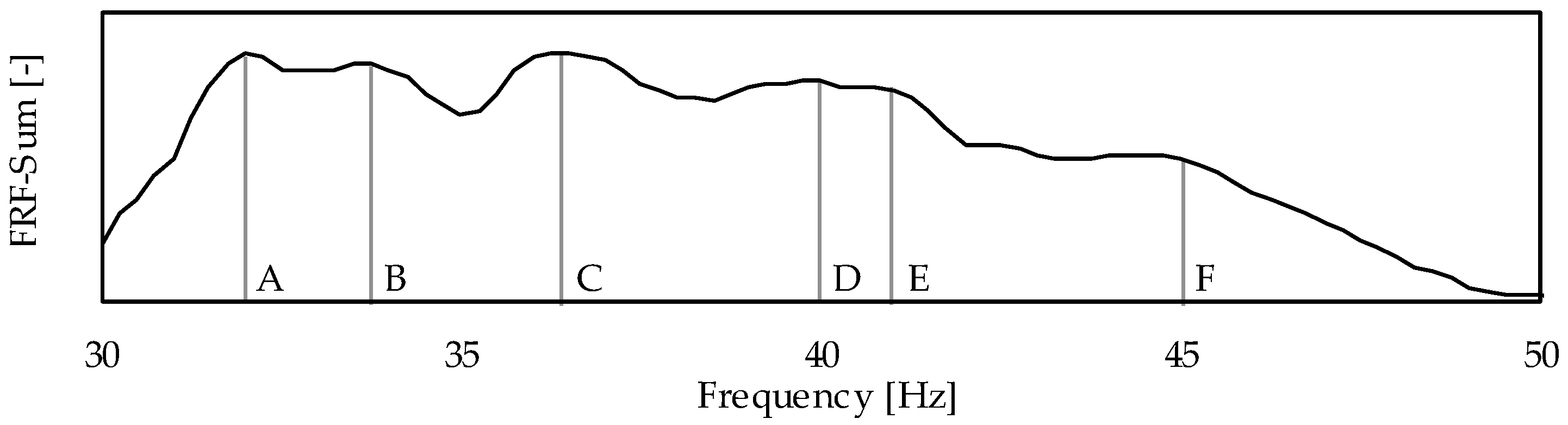
Figure 10 shows the sum of all measured frequency response functions for the cavity and the vehicle structure.
Letters (A, B, C, D, E, and F) mark the striking maximums.
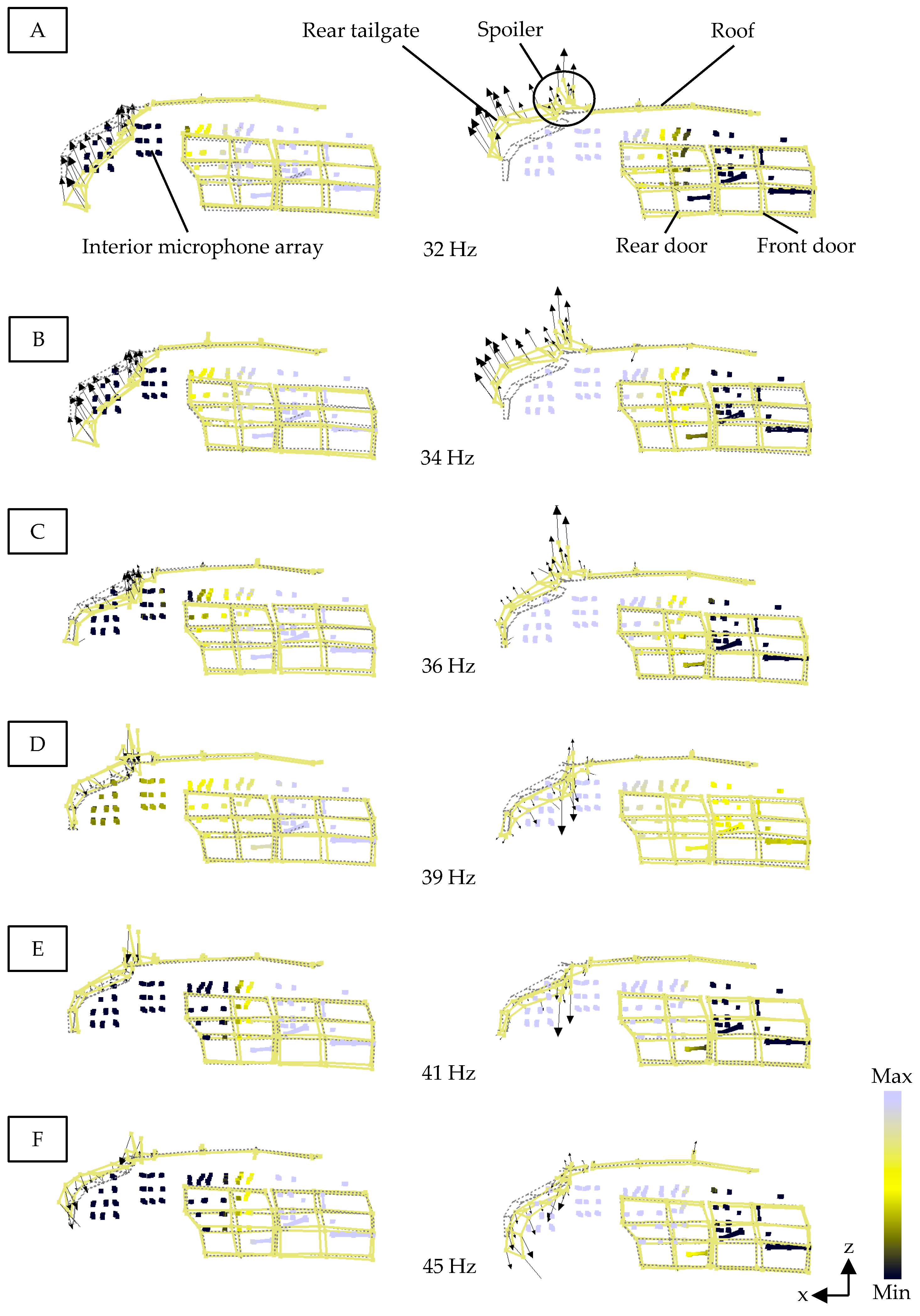
Figure 11 shows the corresponding (coupled) acoustic-structural modes of the interior cavity and the vehicle structure at the marked frequencies.
The first illustration (A) shows the side view of the mode in minimum and maximum deflection on the left and right for the first coupled mode at 32 Hz. The dotted lines represent the undeformed vehicle body structure. The deformed structure is marked with yellow solid lines. The arrows illustrate the deflection and direction of the individual acceleration measurement points on the structure. Each colored dot inside the vehicle’s trimmed body is one of the microphones from the used array. The color depends on the measured sound pressure level.
One can clearly identify that the airborne cavity oscillates in the shape of its first longitudinal mode and is coupled with a rigid body movement of the rear tailgate and its retractable rear spoiler. In comparison, the deflections of the roof and the doors are very small.
The second coupled mode at 34 Hz (B) shows similar results as the first one. Whereas the third (36 Hz, C), fourth (39 Hz, D), and fifth coupled mode (41 Hz, E) are a slightly different. The pulsation of the airborne cavity stays the same, but the deflection of the tailgate decreases while the deflection of the spoiler increases. At 39 Hz (D) and 41 Hz (E) mainly the first bending mode of the spoiler is involved. The last identified coupled mode at 45 Hz (F) consists of the first longitudinal mode of the airborne cavity and rigid body movement of the rear tailgate. Furthermore, a small deflection of the roof is noticeable.
In summary, we conclude that the coupled modes in the investigated frequency range mainly consist of the first longitudinal mode of the airborne cavity as well as a rigid body movement of the rear tailgate and a deflection of its spoiler. Therefore, an accurate definition of the coupling between the airborne cavity and the vehicle structure, especially the tailgate and the spoiler, is essential for the description of road booming noise.
4. Conclusions
In this paper, we investigated the transmitted forces from the rear axle to the vehicle’s body. We identified the relevant input forces and analyzed the influence of two additional rear axle elements on these forces. We then used the gained findings to examine the noise transfer functions of a trimmed body. We focused on the identified rear axle connection points, where the axle applies forces into the vehicle, which are radiated as noise to the driver’s position. Subsequently, we investigated the influence of different vehicle body elements on the noise transfer functions. At last, we performed a vibro-acoustical modal analysis on a trimmed body and examined the coupled modes and the components participating.
This paper shows how the force transmission of the rear axle and the transfer functions to the driver are influenced by different equipment elements. It provides information which elements have no influence on the transmission path and are therefore not relevant for the description of road booming noise.
The following conclusions for describing road booming noise between 20 Hz and 60 Hz are obtained:
The main force transmission paths from the rear axle to the vehicle body are all four subframe mounts in x- and z-direction as well as the shock absorber in z-direction.
The rear axle steering and the active roll stabilization have a major influence on the transmitted forces from the rear axle to the vehicle body.
The noise transfer functions of the trimmed body show a highly distinct maximum, mainly in the transfer functions from all four subframe mount connections in z-direction and the shock absorber in z-direction to the driver’s position.
The forced ventilation openings, the front seats, the headliner, and the cockpit of the trimmed body have little impact on the maximum of the noise transfer functions. Only all remaining trim elements have a significantly high effect on the maximum of the transfer functions.
In the examined frequency band, mainly the first longitudinal mode of the airborne cavity and rigid body movements of the rear tailgate and a deflection of the rear spoiler are identified in several (coupled) acoustic-structural modes.
Since our tests were performed with one vehicle due to the high experimental effort, a transferability of the results to other vehicles should be verified.
For further research, we will create a whole car simulation model based on the gained knowledge. We aim to validate some of the experimental results of this work with the simulation model.

 ,
, 


