
Musculoskeletal Driver Model for the Steering Feedback Controller


1
V.O. Patents & Trademarks, Winthontlaan 6, 3526KV Utrecht, The Netherlands
2
Department of Cognitive Robotics, Delft University of Technology, Mekelweg 2, 2628CD Delft, The Netherlands
3
Steering SW & Controls, Volvo Car Corporation, 405 31 Gothenburg, Sweden
4
Department of Mechanics and Maritime Sciences, Chalmers University of Technology, Hörsalsvägen 7A, 412 96 Gothenburg, Sweden
*
Author to whom correspondence should be addressed.
Vehicles 2021, 3(1), 111-126; https://0-doi-org.brum.beds.ac.uk/10.3390/vehicles3010007
Submission received: 20 January 2021
/
Revised: 8 February 2021
/
Accepted: 19 February 2021
/
Published: 24 February 2021
(This article belongs to the Special Issue Dynamics and Control of Automated Vehicles)
Abstract
:This paper aims to find a mathematical justification for the non-linear steady state steering haptic response as a function of driver arm posture. Experiments show that different arm postures, that is, same hands location on the steering wheel but at different initial steering angles, result in a change in maximum driver arm stiffness. This implies the need for different steering torque response as a function of steering angle, which is under investigation. A quasi-static musculoskeletal driver model considering elbow and shoulder joints is developed for posture analysis. The torque acting in the shoulder joint is higher than in the elbow. The relationship between the joint torque and joint angle is linear in the shoulder, whereas the non-linearity occurs in the elbow joint. The simulation results qualitatively indicate a similar pattern as compared to the experimental muscle activity results. Due to increasing muscle non-linearity at high steering angles, the arm stiffness decreases and then the hypothesis suggests that the effective steering stiffness is intentionally reduced for a consistent on-center haptic response.

1. Introduction
The development of Advanced Driver Assistance Systems (ADAS) and Automated Driving Systems targets to improve vehicle safety, driving comfort and user acceptance. Various Roadmaps and Action Plans [1] predict the exploitation of highly automated vehicles (SAE Level 4 and 5) from 2020; however, their fleet in the coming decades will be increased progressively rather than instantaneously. Hence, the semi-automated driving (SAE Level 2 and 3), keeping the human-in-the-loop, will still dominate resulting in the further development of ADAS as well as the next generation of steering systems. In the state-of-the-art steering systems, the steering feedback is manipulated by the haptic controller. One of the most important cues in the driver–vehicle interaction is the haptic feedback from the steering wheel [2]. It provides the driver with a desired part of the steering feel. This steering feedback is dependent on the haptic control strategy [3,4], which further consists of various software functions. One of them is the basic steering assist function.
1.1. Basic Steering Assist Function
The basic steering assist function creates a non-linear on-center steering response—refer Figure 1—which is represented in terms of steering torque vs. steering wheel angle (SWA), thus defining the effective steering stiffness. This non-linear response is developed objectively and subjectively in an empirical manner using simulations or driving simulator experiments [5,6]. The data shown in Figure 1 and Figure 2 are acquired during a steady state sinus maneuver (at 0.20 Hz steering frequency and 60 km/h vehicle speed) performed by a steering robot in a test vehicle at a proving ground. The effective steering stiffness, at a certain steering angle, increases at higher vehicle speeds. But the paper considers only one vehicle speed to emphasize the hypothesis. Our results will also be qualitatively applicable to all other vehicle speeds.
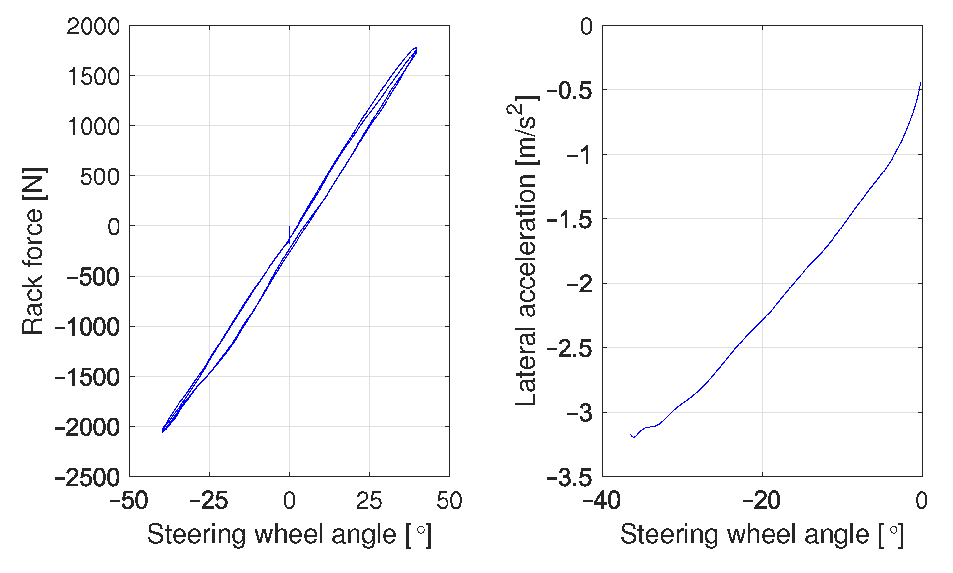
Since a typical on-center steering response is non-linear; such that the effective steering stiffness reduces over an increasing steering angle (Figure 1) and at a given vehicle speed. During this operational range (i.e., within 3–4 m/s2 vehicle lateral acceleration), the steering rack force generated by front axle tire lateral forces and self-aligning moments acting on the steering rack, behaves approximately linearly over the steering angle, see Figure 2. Tire non-linearity around 60 km/h speed occurs at higher lateral acceleration (i.e., for high steering angles on a nominal road surface condition), which we have kept out of context. The lateral acceleration behaves almost linearly over steering angle, as it can be seen in Figure 2. This implies that the non-linearity is not contributed by the front axle tire forces or moments. In fact, the non-linearity in the steering response is caused by the software tuning in the assistance motor and created intentionally by the basic steering assist function [2].
The research goal of the proposed hypothesis is, to objectively investigate the reason behind this on-center steering stiffness shape (see Figure 1) and how this non-linear response is related to the drivers’ musculoskeletal arm posture. This would eventually contribute in understanding and developing the haptic feedback functions as a dependent factor on the driver-steering interface and the corresponding muscle movements during the interaction. To analyze the effect of posture and geometrical muscle movements, we have developed a quasi-static musculoskeletal driver model including different joints for the hand, elbow and shoulder. In future, these kind of multibody driver models could be used more objectively for tuning the haptic response as a function of posture movements in simulations.
1.2. Conventional Control Perspective Driver Models
McRuer was one of the first to come up with a driver model from a control perspective. The crossover model [7] describes a control method in which the order of control denotes the number of integrations between the human and the output of the system being controlled. The general conclusion of the crossover model is that humans can adapt their internal control behaviour to adjust their steering behavior. The human brain adapts by either basing the control behavior on position, velocity or acceleration by making use of prediction or memory.
Opposite to crossover-compensatory models, preview-tracking approaches using future path information are proposed. These models take into account the human anticipation capabilities and based on the current vehicle states, the previewed path to follow over a time horizon, the vehicle dynamics, and the knowledge of their own interaction with the steering wheel interface. These models can be classified as single-point [8,9] and multiple-point preview models [10,11]. However, these models are mainly focused on the path tracking task rather than the haptic feedback task.
In order to investigate the driver’s steering response, one Degree of Freedom linear mass-spring-damper system is used by Pick & Cole [12,13] to analyse the end-point admittance of the driver’s arms. The system identification is done by applying random torque disturbances to the driver’s arms. Muscle co-contraction is found to increase the arm stiffness and damping [12]. The model has later been extended with an improved model of the intrinsic muscle dynamics [14]. Previously intrinsic muscle dynamics are thought to be dominated by a stiffness term [13]. However, Hoult & Cole found that the intrinsic muscle dynamics are dominated by a damping term at low frequencies [15]. The intrinsic and reflexive joint resistance are found to vary strongly with experimental conditions and depend in particular on task instructions, perturbations, posture and applied forces [16].
1.3. Neuromusculoskeletal Driver Models
Sentouh et al. [17] proposed a driver model including steering torque feedback. This model does not include reflex dynamics explicitly. However, the model includes a time delay to indicate the neuromuscular processing delay. The driver model is divided into two levels: preview tracking and compensatory tracking [18], and it takes into account the driver’s sensory dynamics and their effects on steering control. De Vlugt et al. [19,20] developed a neuromusculoskeletal (NMS) model to estimate intrinsic and reflexive properties of the arm muscles. After electromyography (EMG) measurement analysis, the dynamic properties of the arm were estimated. These musculoskeletal (driver) models considered the vehicle dynamics to be linear. Katzourakis et al. [21] adjusted the neuromuscular models of de Vlugt [22] and Abbink [23] to make the new model applicable for large steering wheel angles due to the adaptability to changes in muscle length. Also the model was developed to convert the desired steering angle to the desired muscle force to achieve this angle. However, none of these models consider the relation between the non-linear steering response and the drivers’ musculoskeletal arm posture. In [21], the variation in human arm end-point admittance as a function of the road curvature is analyzed, whereas the role of driving posture is not investigated. Lately, a simplified 2 DoF dynamic model [24] of drivers’ neuromuscular interaction with a steering wheel performing different steering tasks, arm positions, and driver postures, is proposed. However, the more detailed investigations related to musculoskeletal driver’s arm posture are still open.
Therefore the main aim of this research is to find out what causes a desired steering response when investigating the steering posture from a cybernetics perspective (i.e., describing the human in control engineering terms) [25]. The hypothesis is that the musculoskeletal driver’s arm posture could be responsible for the designed steering response. In the Section 2, a 3-dimensional driver model was developed to analyze the joint torques and the experiments were conducted for comparison of qualitative trends in data in Section 3. Simulation and experimental results are analyzed to conclude on the hypothesis in Section 4.
2. Musculoskeletal Driver Model
Typical neuromuscular steering models demonstrate a promise to understand the effect of non-linear driver arm mechanics, that is, combination of inertia, spring and damper elements. For a comprehensive investigation of the driving posture, a model considering 3-dimensional arm mechanics can be used.
2.1. 3-Dimensional Model Characteristics
In order to obtain the relation between the arm posture and the non-linear steering response, the joint torques and angles should be known. Hence, a 3-dimensional model of the human posture needs to be developed to determine the joint angles for different steering angular positions, and finally to compute the joint torques. The following assumptions are considered for the model:
- A quasi-static model is implemented to ensure a unique solution, because only the steady-state behavior is investigated.
- Shoulder and elbow joints are considered, neglecting wrist because of its negligible influence in terms of displacement and force on the overall system.
- In the shoulder joints only x- and y-rotation are considered. This ensures sufficient reachability while not including extra degrees of freedom and realizing a less computationally demanding model.
- The shoulder joint rotation in x-direction is fixed to a constant value to ensure a unique quasi-static solution. This is motivated by the assumption that these angles vary the least compared to the other joint angles during steering.
- The elbow joints are limited to moving in y- and z-direction only to ensure a unique solution while retaining the required reachability on the steering wheel trajectory.
- The mass between the shoulders is fixed in x-, y- and z-direction at the center of mass.
- The endpoints of the forearms (i.e., the hands) are fixed to the steering wheel trajectory in a quarter-to-three steering posture.
- The upper arm is constrained which prevents independent movement with respect to the mass between the shoulders.
- Forearm and upper arm are constrained so they are not allowed to move independent from each other.
- The centers of mass are positioned according to anthropometric standards [26] and, therefore not located exactly in the middle of each body. All other parameters describing limb lengths and masses follow the same anthropometric standards.
2.2. Multibody Arm Model
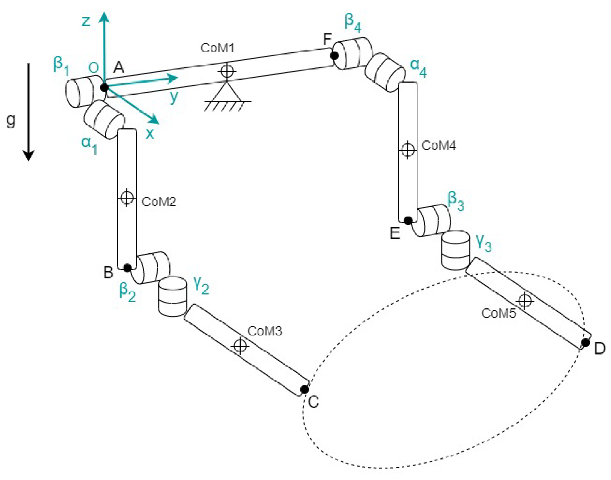
Each arm consists of two rigid bodies connected at the shoulders by a mass representing the head, neck and shoulders. This adds up to a total of five bodies connected by eight hinge joints as shown in Figure 3.
The gravity is assumed to work in the negative z-direction. The independent coordinates and their time derivatives are used to describe the rotations. The Euler angles (xyz) , , and are expressed using rotation matrices , , and . The CoM coordinates of the five bodies, are constructed in terms of the system parameters and angles of rotation.
2.3. Deriving Joint Angles from Steering Wheel Envelope
The reaction torque from the steering wheel is added on the hands (points C and D), acting in the direction of the steering wheel axis. The steering wheel torque reaction on the hands is an external torque input to the multibody model. The method of virtual power and Lagrange multipliers is used to describe all motions using the following force balance.
These are the constrained equations of motion—a set of differential equations that describe the dynamic equilibrium of the system, expressed in the unknown center of mass accelerations , the unknown Lagrange multipliers and the additional kinematic constraints .
The forces acting on the left and right hand are calculated. The total steering wheel force is equally distributed over the two hands. The steering wheel envelope in 3D space is created based on the driving posture [27] and tilt angle of the steering wheel. Because the driver’s posture is varying over steering wheel angle , the joint angles are changing accordingly. The joint angles for a certain are calculated. The angles and are given an initial value of either , or . This ensures that the number of joint DoF is equal to the number of geometrical constraint equations resulting in a unique quasi-static solution. More details can be found in [28].
3. Experiment and Parameter Estimation
In order to analyze the influence of changes in driving posture on the steering response, two experiments were performed. The first experiment compares driving posture for varying steering wheel angles, estimating the musculoskeletal arm admittance parameters (, & ). The goal of the second experiment is to analyze changes in muscle activity during a low frequency sinusoidal motion applied to the steering wheel by the driver.
3.1. Position Task for Varying Steering Wheel Angles
A set of measurement data was used to analyze the effect of postural changes during driving. The experiment was conducted using the force-feedback (FFb) steering test rig. It was equipped with a direct drive of the steer to the force-feedback motor. The motor torque was requested externally using a dSPACE real-time (MicroAutoBox) machine via CAN interface at 1 ms communication time step. The muscle activation of the participant was measured using surface EMG electrodes (pairs of two, equally spaced). All EMG electrodes were placed according to SENIAM standards [29]. The measured currents were recorded by Vitaport using eight channels. The four measured muscles are listed in Table 1 below, including their functionalities for the left arm.
The first experiment was done by exciting the motor with a sinus sweep signal linearly increasing from 0.1 to 20 Hz, where the driver acts as a steering wheel angle position controller with maximum possible resistance (i.e., high arm impedance), thus minimizing the angular deviations.
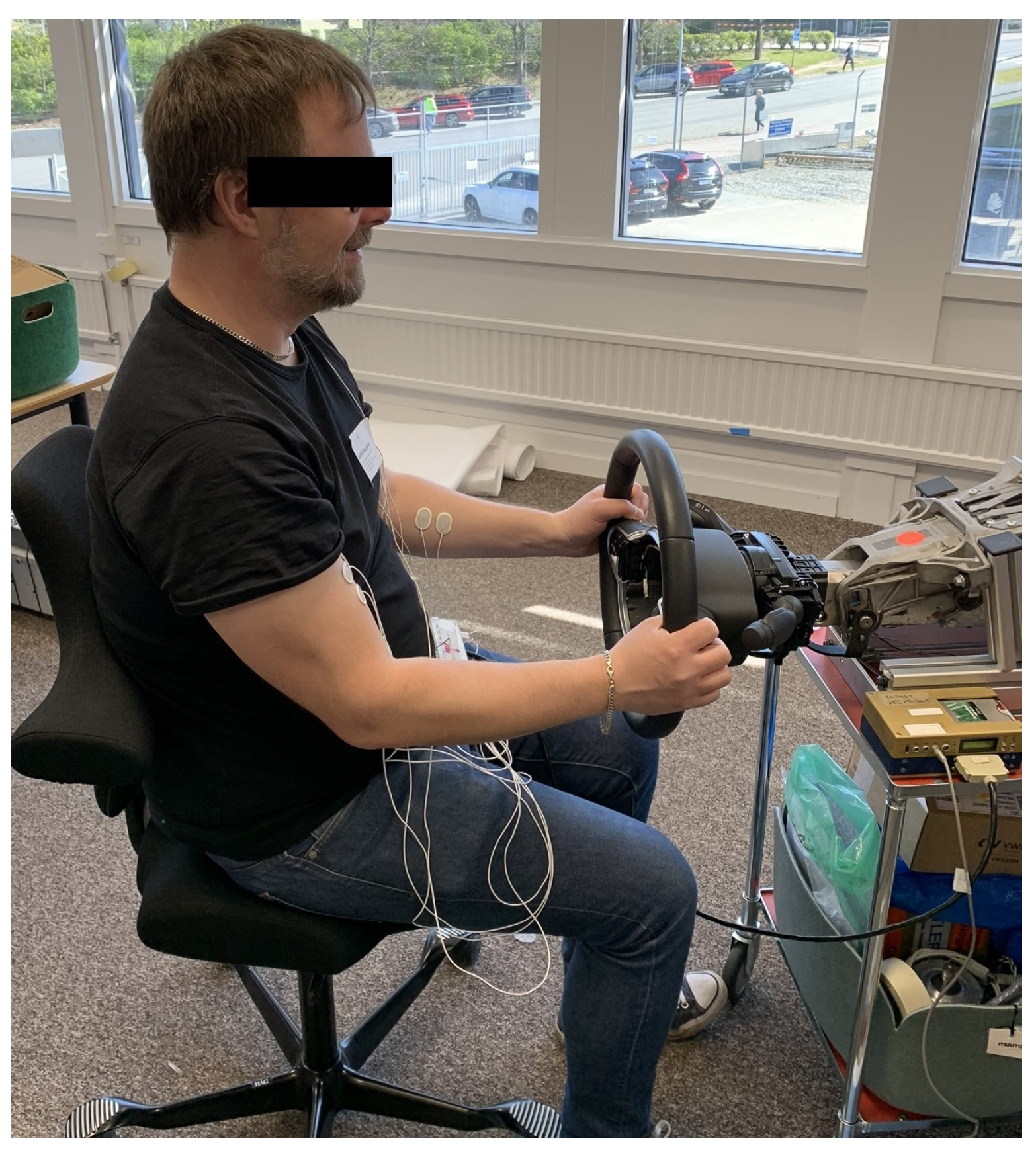
For consistency of the experiment, the following were ensured: (a) quarter-to-three driving position (see Figure 4) of the hands at all times; (b) measurement repeatability with multiple runs considering driver arms’ fatigue; (c) two motor (excitation) torque amplitudes, Nm; and (d) upright posture with only moving hands and arms when applying torque. The inference is as follows:
- Test results almost independent of the torque levels.
- A similar frequency response behavior for the same positive and negative steering angular position tests.
The time based differential equations of the steering system including the steering inertia-spring-damper parameters (), the steering torque and motor torque are defined in Equation (2).
After applying the Laplace transformation to the differential equations, the frequency response function (FRF) from steering torque to steering angular position or velocity can be defined as admittance, given in Equation (3), containing information regarding the effective (or 1 DoF) inertia-spring-damper parameters for each test respectively. From the measured FRF admittance function the parameters can subsequently be estimated.
It is also possible to use the motor torque signal for the FRF plots instead of steering torque signal, such that the total inertia and total damping are used in the above definition, such that:
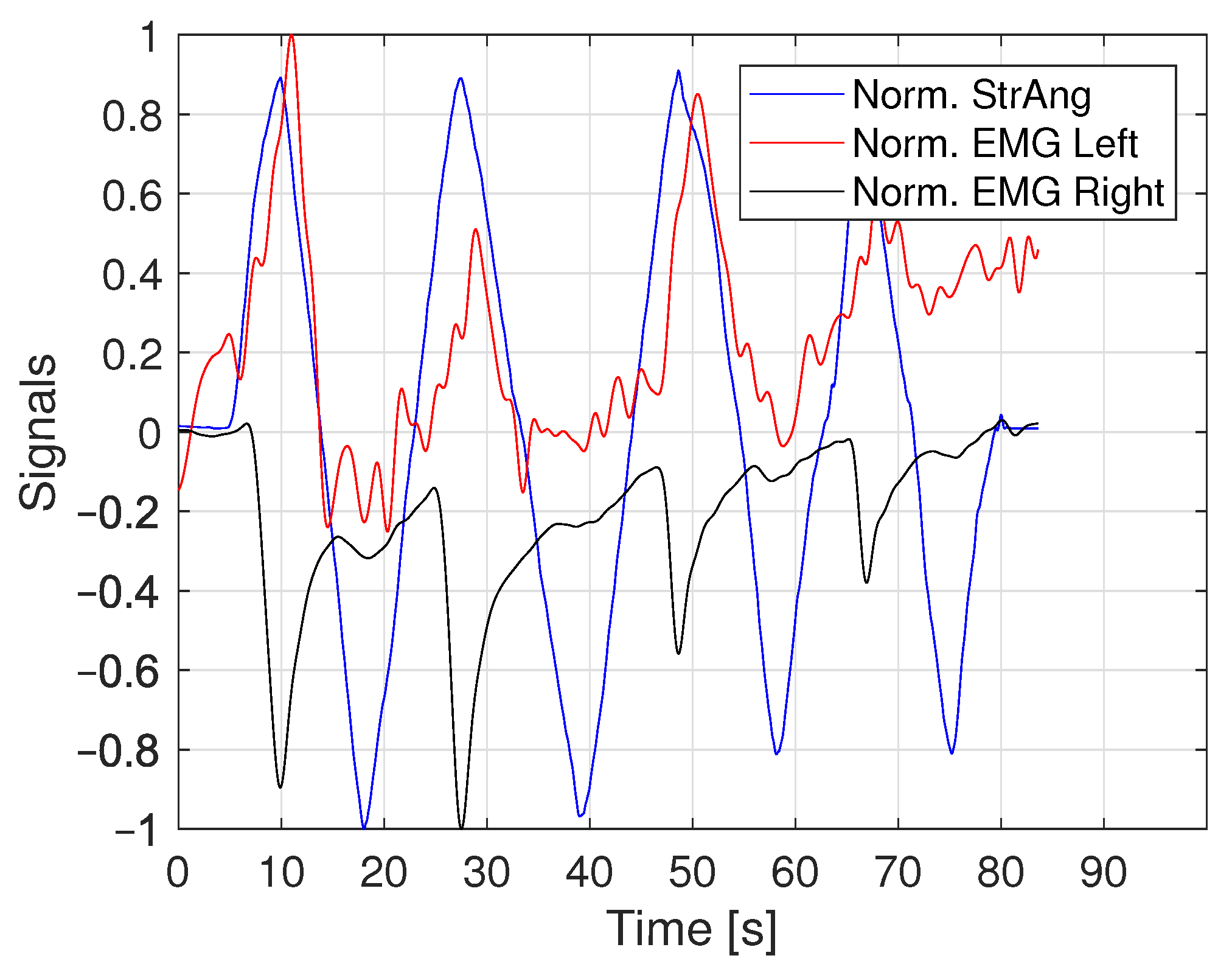
3.2. Sinus Motion Applied by Driver
In the second measurement scenario, multiple low frequency sinusoidal movements were applied to the steering wheel by the participant. There was no other disturbance applied to the steering wheel. In this case the motor torque was described by a linear spring stiffness. This implies that the steering stiffness was constant at all steering wheel angles.
The variables measured in this experiment were eight EMG signals (four for each arm, see Table 1), the steering wheel angle , the driver applied torque and the motor torque . The steering wheel diameter was 0.315 m.
4. Results and Discussion
The model is limited to eight rotational degrees of freedom which result in a unique solution for every steering wheel angle, whereas the real-life human arm posture with more degrees of freedom does not result in a unique solution. Therefore the results are analyzed from a qualitative perspective and all the values are normalized.
The overall arm end-point admittance from the experimental data was estimated with a high coherence and is therefore considered to be reliable for all participants. The EMG data contain very large deviations between participants due to differences in electrode placement. Due to a low-frequency drift over time caused by motor learning [30], the EMG activity in terms of magnitude cannot be compared. Cross–talk between muscles, surrounding electro–magnetic fields and poor skin conductivity, could cause noise in EMG measurement data [31]. Therefore, the model is merely qualitatively comparable to the experimental data. The experiments were performed with only a few participants completing all scenarios. For clarity purposes, the results in muscle activity are illustrated by the results of a typical participant.
4.1. Frequency Response Function Results
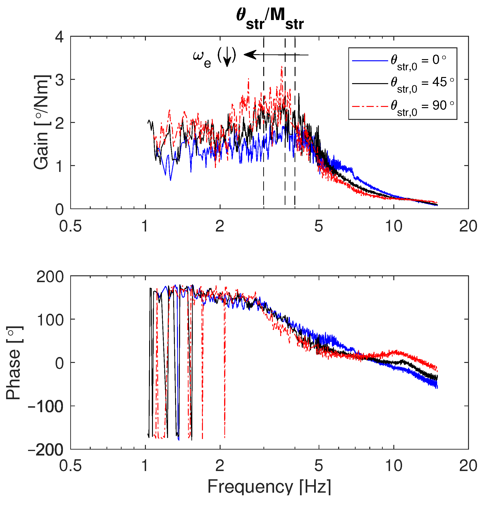
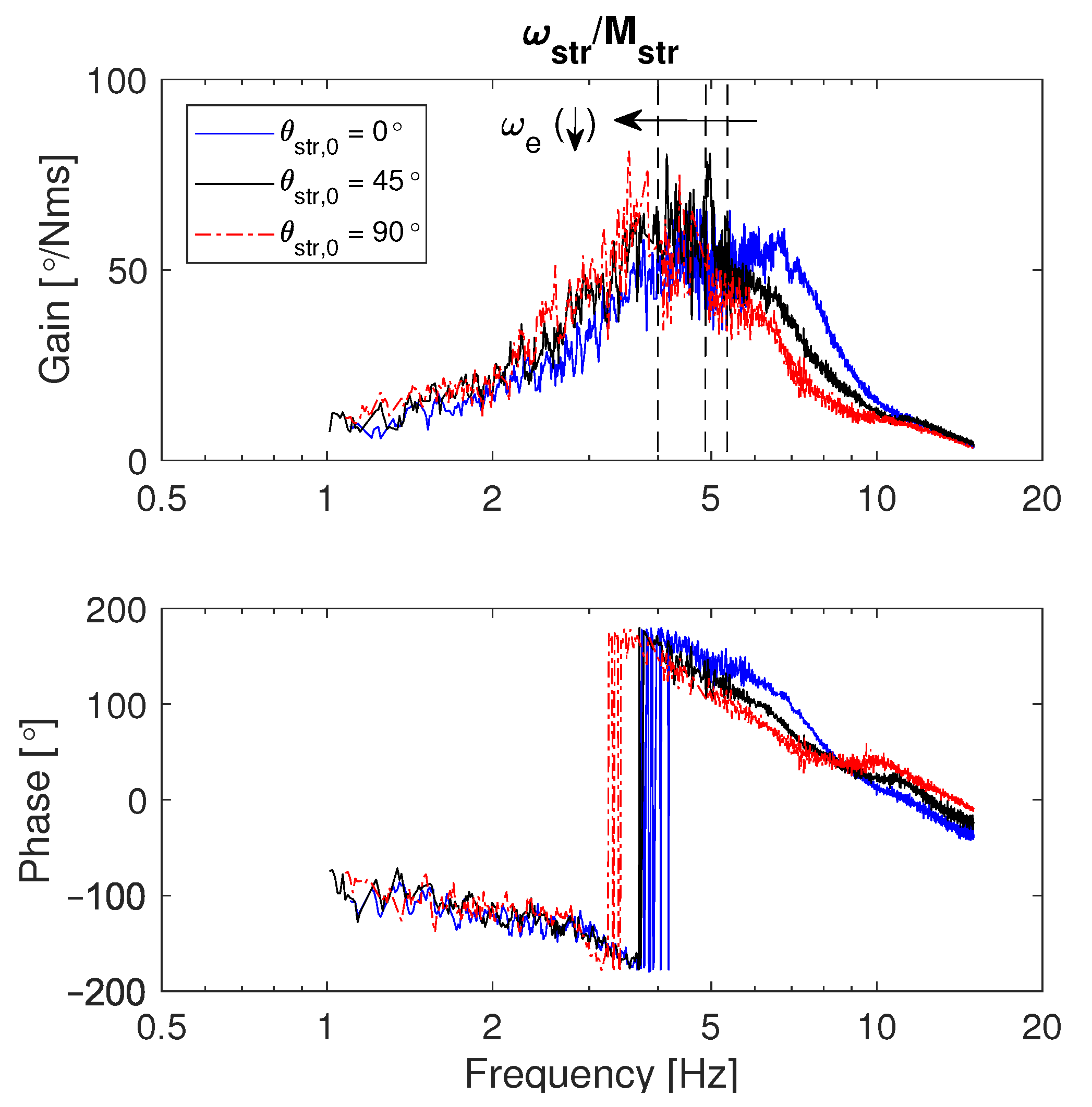
Figure 5 shows the FRF from steering torque to steering angular position. The frequency response plot corresponding to Equation (3), is given in Figure 6.
The FRF gain and phase are plotted over Hz frequency range. It includes the data from three different steering angular positions (i.e., and ) with an excitation torque level of 1 Nm. The steering wheel inertia was equal to 0.03 kgm2. The steering wheel damping was 0.065 Nms/rad. The system was rigid and therefore the stiffness approaches infinity as there was no compliance.
The main observation from this result in Figure 6 is the drop in first FRF eigenfrequency with increasing steering angular position, particularly from to . This implies either decreasing or increasing or both. In Figure 5, the increasing steady state value over an increasing steering angle initial position explicitly explains the cause of a decreasing . Due to conservation of mass for a physical driver arm and considering the same driver, the effective inertia is more or less independent of different initial angular positions. Therefore, the drop in eigenfrequency is primarily caused by the drop in effective arm stiffness with an increasing steering angle.
To investigate the decrease of over an increasing steering angular position, EMG measurements were performed. This provided an opportunity to analyze the effect of driving arm posture, that is, variation in joint torques over joint angles or steering wheel angle for understanding the steady state behavior.
4.2. Simulation Approach
Given a torque profile resulting from a linear spring stiffness with a maximum of 3 Nm, the relation between steering torque and steering wheel angle is defined in Equation (5).
The relation between and is calculated. Using the applied steering torque and the Energy and Lagrange EoM, the relation between applied torque and joint torque is calculated. Therefore the following relations are known.
After completing the model describing the steady-state multibody arm model in 3D, the resulting joint torque versus joint angle relations were computed. The goal was to compute the joint torques over varying joint angles due to varying steering posture. Therefore the rate of change in joint torques over joint angles, that is, the desired output of the driver model, is mathematically related to the rate of change in steering torque input over steering wheel angle in the form of partial derivate equations as:
Due to the qualitative comparison between the model and experimental data, the rate of change in joint torques and joint angles is computed. The relation between joint torque and joint angle can be defined using the rotational joint stiffness .
The joint stiffness can be defined as the rate of change in joint torques with respect to their joint angles. The partial derivative of the joint torque over joint angle results in the following relation.
This relation ensures the change in stiffness of the joints can be calculated. The joint stiffness is related to the muscle contraction, and therefore provides more information about the biomechanics of the posture for various .
4.3. Linear Relation in Shoulder Joint
The experimental scenario in which the driver applies a low frequency sinusoidal movement to the steering wheel is considered. In this case the shoulders are fixed to and therefore is not varying over and remains zero as can be seen from Figure 7.
It can be seen in Figure 8 that the joint torque versus joint angle relation is partially linear in the shoulder for one of the rotation directions and becomes non-linear at the higher steering wheel angles when varying over steering wheel angles. Figure 8 shows linear behavior of the shoulder joint torques (i.e., having a linear stiffness) when the steering posture is varying over joint angles. The rotation stiffness is 0.0529 Nm/deg and the slope in the joint torque vs. joint angle plot is constant.
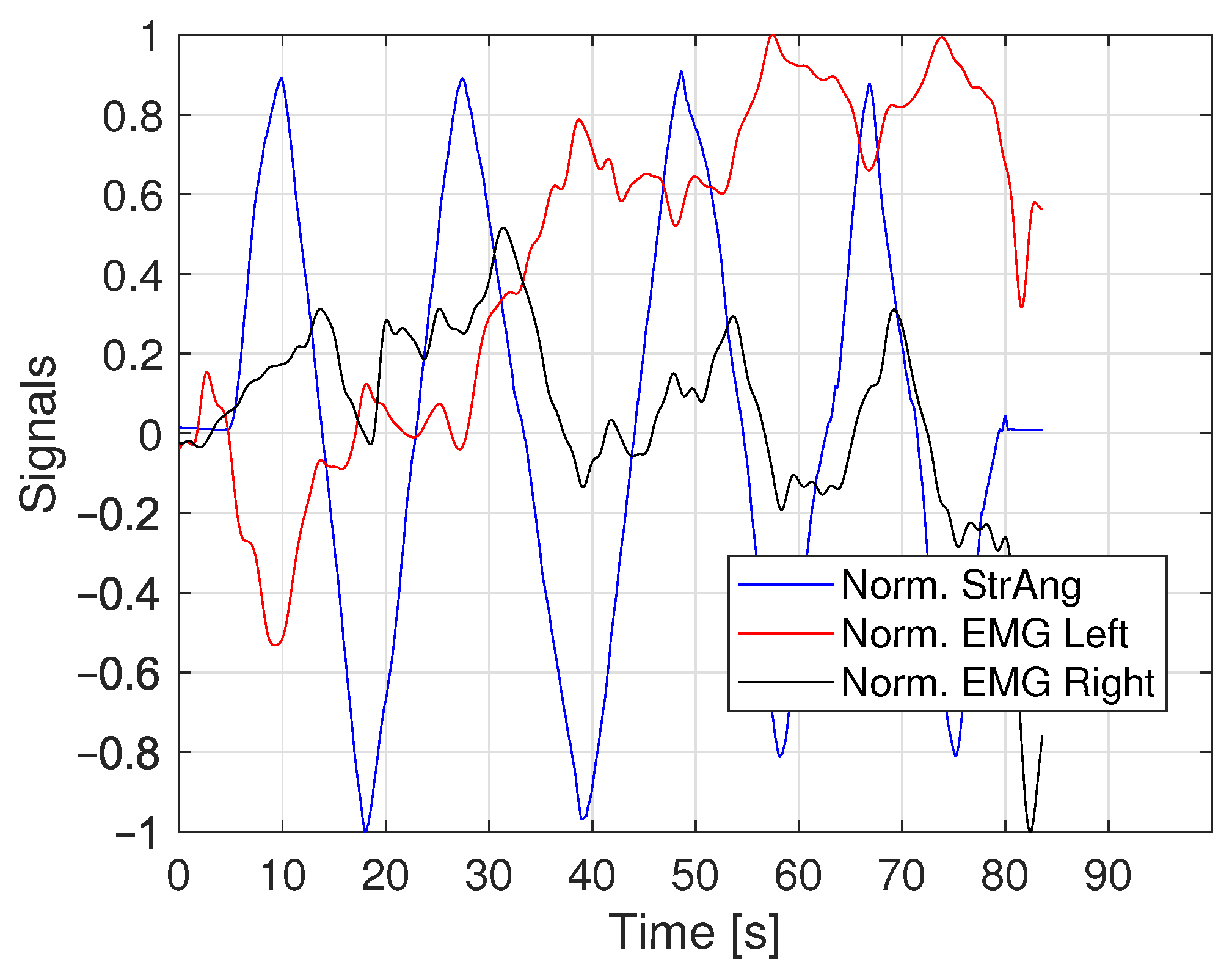
The EMG activity of the Deltoideus Anterior (DA) muscle during this low frequency sinus measurement is shown in Figure 9. As the quantitative EMG data contains bias and random errors due to muscle memory and measurement noise, only trends in these values are analyzed.
The muscle activity of the front shoulder muscle (Figure 10) resembles the shoulder joint torque. The change in EMG activity over varying steering wheel angle is approximately linear. This is notable, since the change in joint torque over steering wheel angle from the driver model simulation was for the largest contribution linear as well for one of the rotation directions (Figure 7). In terms of magnitude, the driver model data shows relatively high values in shoulder joint torque compared to the elbow data.
4.4. Non-Linear Relation in Elbow Joint
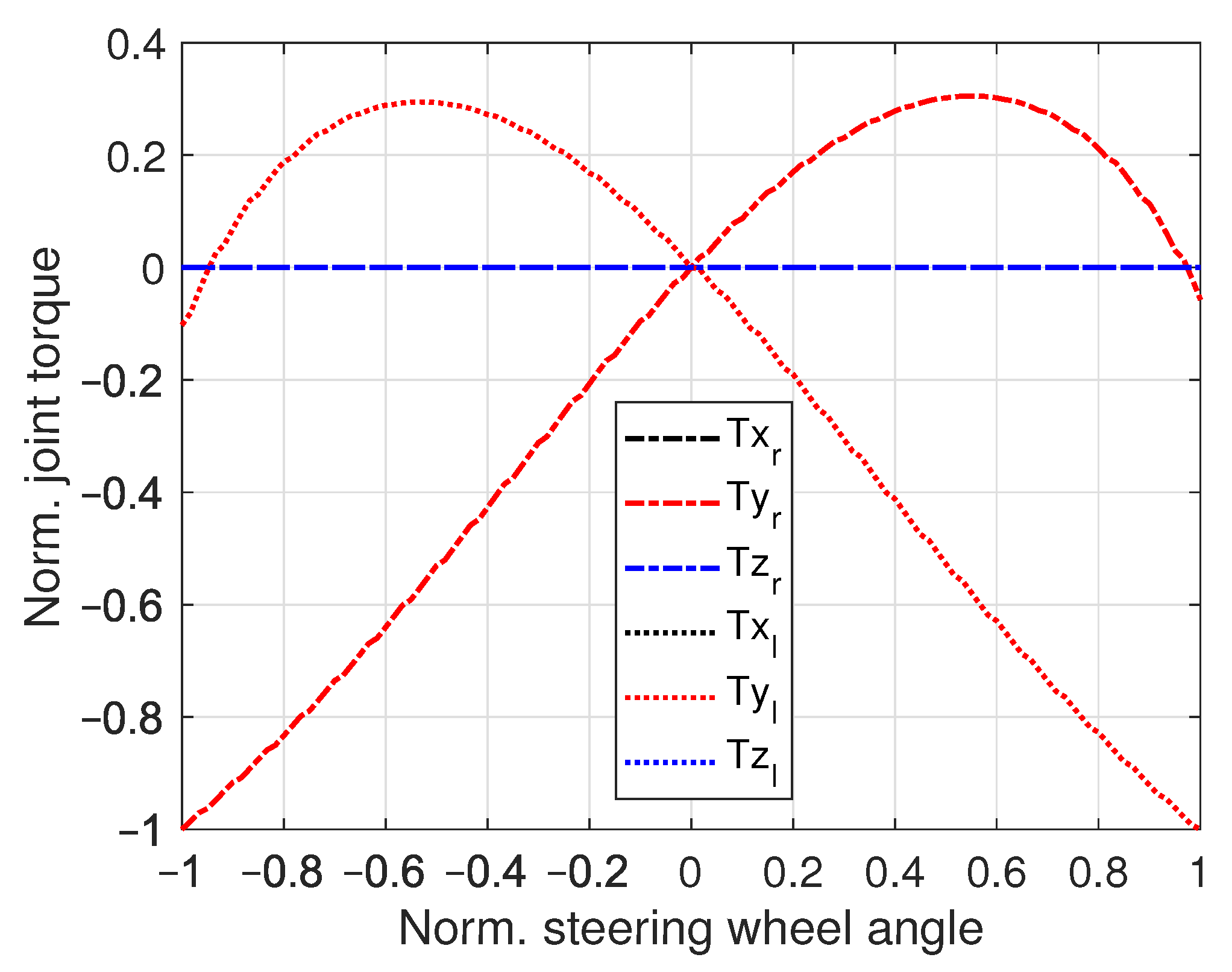
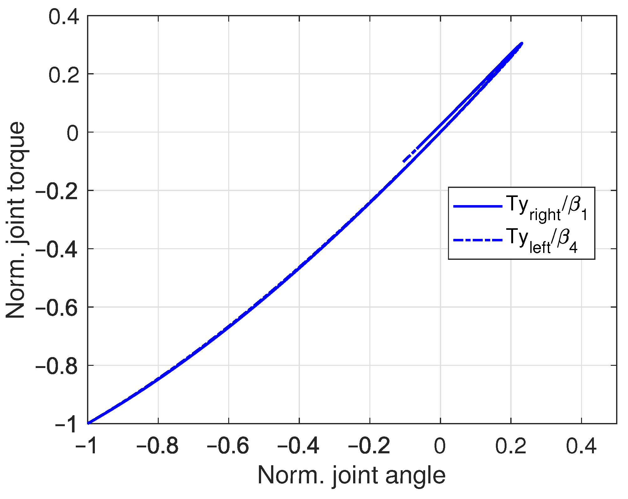
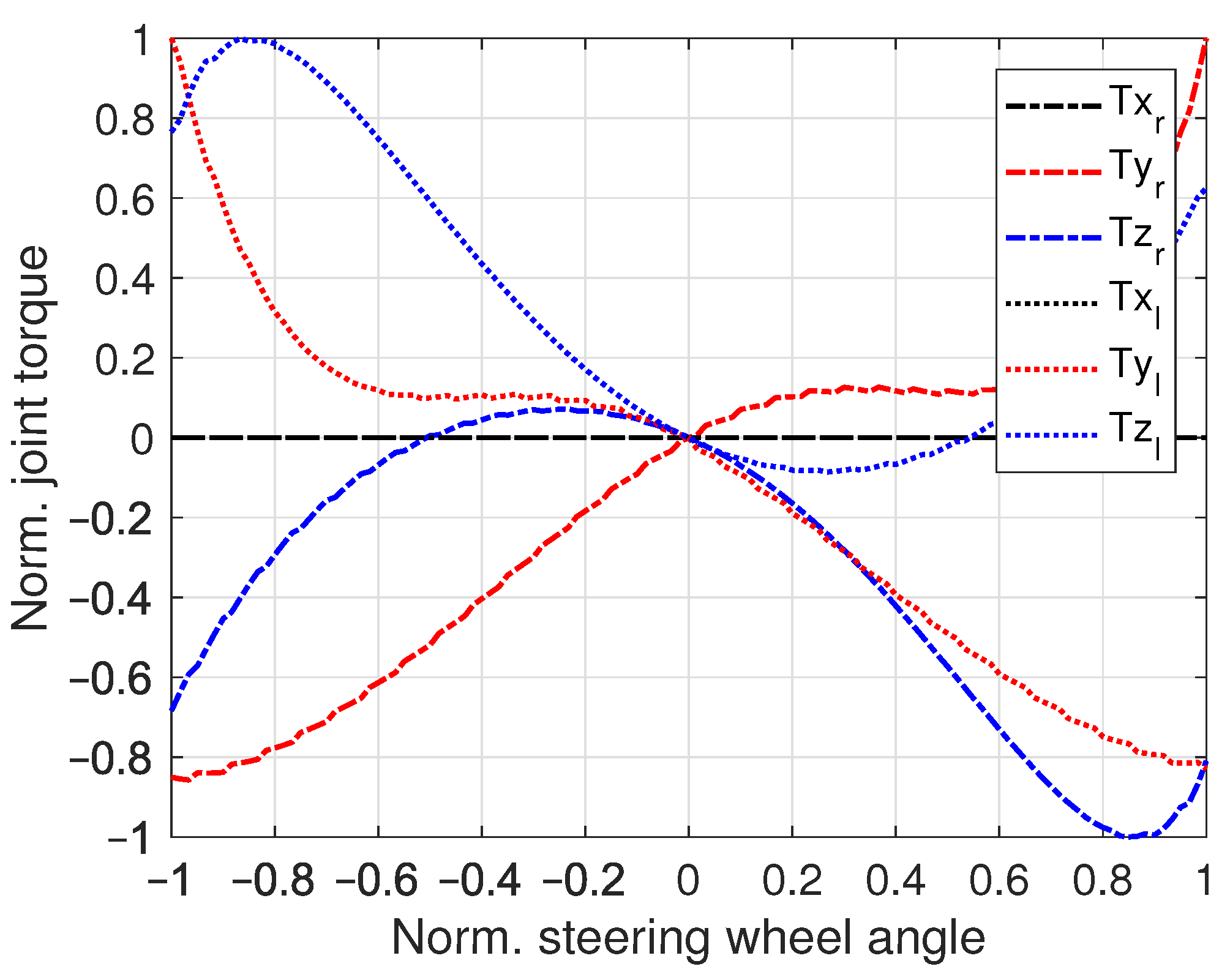
The stiffness in the elbow joint is varying over (i.e., varying steering wheel angles). The initial position at is quarter to three. The driver model simulation results are shown in Figure 11 and Figure 12. The values in joint torque versus steering wheel angle graphs are normalized for qualitative analysis.
The rotational degrees of freedom in the driver model are limited to y- and z-axis rotation. Therefore the rotational joint torque in x-direction remains zero for all steering wheel angles (Figure 11). The rotational torques in y- and z-direction in the elbow joint show a non-linear symmetric behaviour over varying steering wheel angle. In Figure 12 the joint torque over joint angle graph shows a non-linear relation as well.
For the postures where the hand is moving from side to top of the steering wheel, the torque over angle relation is close to linear for both and rotations (see Figure 11 and Figure 12). In the postures where the hand is moving from side to bottom of the steering wheel, the torque over angle relation is non-linear for and . The same holds for the left arm and the joint rotations and .
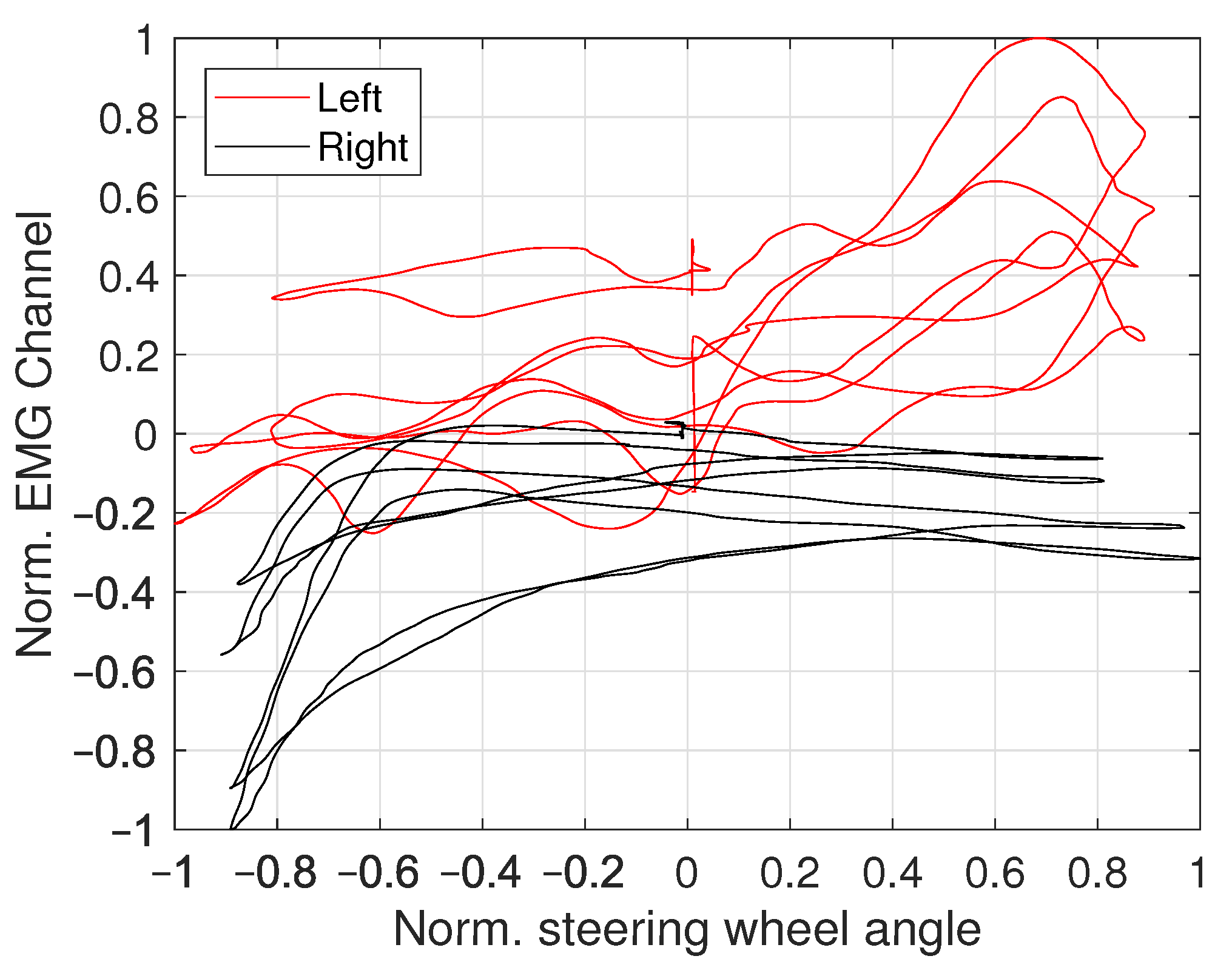
The EMG activity of the FC muscle during the sine sweep maneuver is shown in Figure 13 for the lower arm muscle, which generates a force acting on the elbow. Therefore this muscle’s data is compared to the elbow joint torque from the driver model simulation results.
In Figure 14, the muscle activity of the lower arm muscle is shown over normalized steering wheel angle. The change in EMG activity over varying steering wheel angle demonstrates non-linear trends for off-centre steering wheel angles. Similar behaviour was seen in the joint torque versus steering wheel angle results from the driver model (Figure 11). In terms of magnitude, the elbow data shows relatively smaller values compared to the shoulder data.
5. Conclusions
The frequency response measurements show that the maximum estimated driver arm stiffness reduces with an increasing steering angular position, while keeping the same location of hands on the steering wheel. This lays the foundation of our research problem and it implies, the role of driving arm posture in creating a desired non-linear on-center steering haptic response. A decreasing muscular arm stiffness with an increasing steering wheel angle, thus requires an increasing assistance from the servo motor for a consistent feeling. As a result, the rate of change of steering torque over steering angle is knowingly created with a non-linear trend, to overcome the effects of changing arm posture which is subsequently causing a reduction in arm stiffness. We have also shown that there is no other external influence of tire and vehicle non-linear effects using measurements from a real vehicle.
To investigate and analyze this problem further, we have developed a 3-Dimensional musculoskeletal driver model. This multibody driver model indicate similar qualitative trends as the experimental results from the muscle activity. The following conclusions can be drawn from the simulation and experimental results.
- The torque distribution over the joints is matching the expectation that a large number of muscles or a relatively large physiological cross-sectional area (PCSA) generates a high muscle torque.
- The change in joint torque over steering wheel angle is found to be partially linear in the shoulder joint for one of the rotation directions in both simulation and experimental results.
- The non-linearity in joint torque over steering wheel angle are present in the elbow joint. This result was noticeable in simulation as well as experimental data.
- A decreasing arm stiffness requires the driver to be aided more at high steering wheel angles. This can be explained using the response of joint torques which are dependent on the driving arm posture.
Our study has investigated the dependency between the steady-state on-center haptic response and the driver arm posture while steering. Although the exact quantified relationship has not been identified between the theory and experiment findings, but we have exhibited qualitative and indicative similarities. These results would be useful in tuning the haptic feedback functions for a given driver-steering interaction setup. Also, a change in haptic interface would result in a different required haptic response due to changed driver-steering posture. Thus, the steering feedback should be re-designed using a similar multibody driver model, as developed in our work, for new methods of haptic interfaces, for example joysticks, trackball and so forth.
For future work, the musculoskeletal driver model should be improved with reduced assumptions and by considering the dynamics movements for inertial torque components. We also aim to perform similar experiments with different steering haptic interfaces. To validate and compare these results in a more quantitative manner. This would subsequently be useful for objectively tuning the basic assist function in steering controllers, considering a given haptic interface and the corresponding muscle’s movement.
Author Contributions
Research, methodology and validation L.S., T.C., F.B. and B.S.; Writing, L.S., T.C.; Supervision, T.C., F.B. and B.S. All authors have read and agreed to the published version of the manuscript.
Funding
This research was funded by the International Federation of Automotive Engineering Societies (FISITA) as a scholarship via the Travel Bursary. The measurement equipment was funded by Chalmers University of Technology. Furthermore support was received from the Steer-by-wire Opportunities, performance and system safety (SWOPPS) project from the strategic vehicle research and innovation (FFI) programme.
Institutional Review Board Statement
The study was conducted according to the guidelines of the Compliance and Ethics Office of Volvo Car Corporation.
Informed Consent Statement
Informed consent was obtained from all subjects involved in the study.
Acknowledgments
The work presented in this paper was supported by The Swedish National Road and Transport Research Institute (VTI) and Volvo Car Corporation.
Conflicts of Interest
The authors declare no conflict of interest.
Abbreviations
The following abbreviations are used in this manuscript:
| SWA | Steering Wheel Angle |
| NMS | Neuromusculoskeletal |
| EMG | Electromyography |
| DoF | Degree of Freedom |
| CoM | Center of Mass |
| DAE | Differential Algebraic Equation |
| FFb | Force-Feedback |
| SENIAM | Surface Electromyography for the Non-Invasive Assessment of Muscles |
| BB | Biceps Brachii |
| FC | Flexor Carpi Radialis |
| DA | Deltoideus Anterior |
| CP | Deltoideus Posterior |
| FRF | Frequency Response Function |
| PCSA | Physiological Cross-Sectional Area |
References
- Dokic, J.; Müller, B.; Meyer, G. European Roadmap Smart Systems for Automated Driving; European Technology Platform on Smart Systems Integration: Brussels, Belgium, 2015; pp. 1–39. [Google Scholar]
- Chugh, T. Haptic Feedback Control Methods for Steering Systems. Licentiate Thesis, Chalmers University of Technology, Gothenburg, Sweden, 2019. [Google Scholar]
- Chugh, T.; Bruzelius, F.; Klomp, M.; Shyrokau, B. Design of haptic feedback control for steer-by-wire. In Proceedings of the IEEE 21st International Conference on Intelligent Transportation Systems, Maui, HI, USA, 4–7 November 2018; pp. 1737–1744. [Google Scholar]
- Chugh, T.; Bruzelius, F.; Klomp, M.; Shyrokau, B. An approach to develop haptic feedback control reference for steering systems using open-loop driving manoeuvres. Veh. Syst. Dyn. 2020, 58, 1953–1976. [Google Scholar] [CrossRef]
- Damian, M.; Shyrokau, B.; Ocariz, A.; Akutain, X.C. Torque control for more realistic hand-wheel haptics in a driving simulator. In Proceedings of the Driving Simulation Conference Europe, Strasbourg, France, 4–6 September 2019. [Google Scholar]
- Shyrokau, B.; De Winter, J.; Stroosma, O.; Dijksterhuis, C.; Loof, J.; van Paassen, R.; Happee, R. The effect of steering-system linearity, simulator motion, and truck driving experience on steering of an articulated tractor-semitrailer combination. Appl. Ergon. 2018, 71, 17–28. [Google Scholar] [CrossRef] [PubMed]
- McRuer, D.T.; Jex, H.R. A review of quasi-linear pilot models. IEEE Trans. Hum. Factors Electron. 1967, HFE-8, 231–249. [Google Scholar] [CrossRef] [Green Version]
- Kondo, M.; Ajimine, A. Driver’s Sight Point and Dynamics of the Driver-Vehicle-System Related to It; SAE International: Warrendale, PA, USA, 1968. [Google Scholar]
- Guo, K.; Guan, H. Modelling of driver/vehicle directional control system. Veh. Syst. Dyn. 1993, 22, 141–184. [Google Scholar] [CrossRef]
- MacAdam, C.C. Application of an optimal preview control for simulation of closed-loop automobile driving. IEEE Trans. Syst. Man Cybern. 1981, 11, 393–399. [Google Scholar] [CrossRef]
- Sharp, R.; Valtetsiotis, V. Optimal preview car steering control. Veh. Syst. Dyn. 2001, 35, 101–117. [Google Scholar]
- Pick, A.; Cole, D.J. Dynamic properties of a driver’s arms holding a steering wheel. Proc. Inst. Mech. Eng. Part D J. Automob. Eng. 2007, 221, 1475–1486. [Google Scholar] [CrossRef]
- Pick, A.J.; Cole, D.J. A mathematical model of driver steering control including neuromuscular dynamics. J. Dyn. Syst. Meas. Control 2008, 130, 031004. [Google Scholar] [CrossRef]
- Cole, D.J. A path-following driver–vehicle model with neuromuscular dynamics, including measured and simulated responses to a step in steering angle overlay. Veh. Syst. Dyn. 2012, 50, 573–596. [Google Scholar] [CrossRef]
- Hoult, W.; Cole, D.J. A neuromuscular model featuring co-activation for use in driver simulation. Veh. Syst. Dyn. 2008, 46, 175–189. [Google Scholar] [CrossRef]
- Happee, R.; De Vlugt, E.; Schouten, A.C. Posture maintenance of the human upper extremity; identification of intrinsic and reflex based contributions. SAE Int. J. Passeng. Cars-Mech. Syst. 2008, 1, 1125–1135. [Google Scholar] [CrossRef]
- Sentouh, C.; Chevrel, P.; Mars, F.; Claveau, F. A Human-Centered Approach of Steering Control Modeling. In Proceedings of the 21st IAVSD Symposium on Dynamics of Vehicles on Roads and Tracks, Stockholm, Sweden, 17–21 August 2009; pp. 1–12. [Google Scholar]
- Donges, E. A two-level model of driver steering behavior. Hum. Factors 1978, 20, 691–707. [Google Scholar] [CrossRef]
- de Vlugt, E.; Schouten, A.C.; van der Helm, F.C. Closed-loop multivariable system identification for the characterization of the dynamic arm compliance using continuous force disturbances: A model study. J. Neurosci. Methods 2003, 122, 123–140. [Google Scholar] [CrossRef]
- Van der Helm, F.C.; Schouten, A.C.; de Vlugt, E.; Brouwn, G.G. Identification of intrinsic and reflexive components of human arm dynamics during postural control. J. Neurosci. Methods 2002, 119, 1–14. [Google Scholar] [CrossRef]
- Katzourakis, D.I.; Abbink, D.A.; Velenis, E.; Holweg, E.; Happee, R. Driver’s arms’ time-variant neuromuscular admittance during real car test-track driving. IEEE Trans. Instrum. Meas. 2013, 63, 221–230. [Google Scholar] [CrossRef]
- De Vlugt, E.; Schouten, A.C.; Van Der Helm, F.C. Quantification of intrinsic and reflexive properties during multijoint arm posture. J. Neurosci. Methods 2006, 155, 328–349. [Google Scholar] [CrossRef] [PubMed]
- Abbink, D.A.; Mulder, M.; Van Paassen, M.M. Measurements of muscle use during steering wheel manipulation. In Proceedings of the 2011 IEEE International Conference on Systems, Man, and Cybernetics, Anchorage, AK, USA, 9–12 October 2011; pp. 1652–1657. [Google Scholar]
- Lv, C.; Wang, H.; Cao, D.; Zhao, Y.; Auger, D.J.; Sullman, M.; Matthias, R.; Skrypchuk, L.; Mouzakitis, A. Characterization of driver neuromuscular dynamics for human–automation collaboration design of automated vehicles. IEEE/ASME Trans. Mechatron. 2018, 23, 2558–2567. [Google Scholar] [CrossRef] [Green Version]
- Mulder, M.; Pool, D.M.; Abbink, D.A.; Boer, E.R.; Zaal, P.M.; Drop, F.M.; van der El, K.; van Paassen, M.M. Manual control cybernetics: State-of-the-art and current trends. IEEE Trans. Hum. Mach. Syst. 2017, 48, 468–485. [Google Scholar] [CrossRef]
- Winter, D. Anthropometry. In Biomechanics and Motor Control of Human Movement; Wiley: Hoboken, NJ, USA, 1990. [Google Scholar]
- Andreoni, G.; Santambrogio, G.C.; Rabuffetti, M.; Pedotti, A. Method for the analysis of posture and interface pressure of car drivers. Appl. Ergon. 2002, 33, 511–522. [Google Scholar] [CrossRef]
- Schenk, L. Musculoskeletal Driver Model for the Steering Feedback Controller. Master’s Thesis, Delft University of Technology, Delft, The Netherlands, 2020. [Google Scholar]
- SENIAM group Recommendations for Sensor Locations on Individual Muscles. Available online: http://www.seniam.org/ (accessed on 12 January 2021).
- Schmidt, R.A.; Wrisberg, C.A. Motor Learning and Performance: A Situation-Based Learning Approach; Human Kinetics Publishers: Champaign, IL, USA, 2008. [Google Scholar]
- De Luca, C.J. The use of surface electromyography in biomechanics. J. Appl. Biomech. 1997, 13, 135–163. [Google Scholar] [CrossRef] [Green Version]
Figure 1.
Typical on-center response, exhibiting the software developed non-linear relation between the steering wheel angle and the steering torque.
Figure 1.
Typical on-center response, exhibiting the software developed non-linear relation between the steering wheel angle and the steering torque.

Figure 2.
A linear relation between the steering wheel angle and the steering rack force as well as the lateral acceleration.
Figure 2.
A linear relation between the steering wheel angle and the steering rack force as well as the lateral acceleration.

Figure 3.
Illustrative diagram of the human arms.

Figure 4.
Participant holding the steer in quarter-to-three hand to steering wheel position.

Figure 5.
Measured frequency response function (FRF) for three steering angular positions ( and ) from steering torque to steering angular position.
Figure 5.
Measured frequency response function (FRF) for three steering angular positions ( and ) from steering torque to steering angular position.

Figure 6.
Measured FRF for three steering angular positions ( and ) from steering torque to steering angular velocity.
Figure 6.
Measured FRF for three steering angular positions ( and ) from steering torque to steering angular velocity.

Figure 7.
Normalized shoulder joint torques over normalized steering wheel angle.

Figure 8.
Normalized shoulder joint torques over normalized joint angle.

Figure 9.
Normalized EMG activity Deltoideus Anterior (DA) (front shoulder) muscle over time.

Figure 10.
Normalized muscle activity over normalized steering wheel angle (front shoulder).

Figure 11.
Normalized elbow joint torques over normalized steering wheel angle.

Figure 12.
Normalized elbow joint torques over normalized joint angle.

Figure 13.
Normalized EMG activity Flexor Carpi Radialis (FC) (i.e., lower arm) over time.

Figure 14.
Normalized muscle activity over normalized steering wheel angle.


Table 1.
Measured muscles and their functionalities [23].
Table 1.
Measured muscles and their functionalities [23].
| Muscle Name | Location | Functionality Left Arm |
|---|---|---|
| Biceps Brachii (BB) | Upper arm | Aids in steering left |
| Flexor Carpi Radialis (FC) | Lower arm | Gripping the wheel |
| Deltoideus Anterior (DA) | Shoulder | Aids in steering right |
| Deltoideus Posterior (DP) | Shoulder | Aids in steering right |
Publisher’s Note: MDPI stays neutral with regard to jurisdictional claims in published maps and institutional affiliations. |
© 2021 by the authors. Licensee MDPI, Basel, Switzerland. This article is an open access article distributed under the terms and conditions of the Creative Commons Attribution (CC BY) license (http://creativecommons.org/licenses/by/4.0/).
Share and Cite
MDPI and ACS Style
Schenk, L.; Chugh, T.; Bruzelius, F.; Shyrokau, B. Musculoskeletal Driver Model for the Steering Feedback Controller. Vehicles 2021, 3, 111-126. https://0-doi-org.brum.beds.ac.uk/10.3390/vehicles3010007
AMA Style
Schenk L, Chugh T, Bruzelius F, Shyrokau B. Musculoskeletal Driver Model for the Steering Feedback Controller. Vehicles. 2021; 3(1):111-126. https://0-doi-org.brum.beds.ac.uk/10.3390/vehicles3010007
Chicago/Turabian StyleSchenk, Lydia, Tushar Chugh, Fredrik Bruzelius, and Barys Shyrokau. 2021. "Musculoskeletal Driver Model for the Steering Feedback Controller" Vehicles 3, no. 1: 111-126. https://0-doi-org.brum.beds.ac.uk/10.3390/vehicles3010007