Investigation of Guided Wave Interaction with Discontinuities in the Axisymmetric Damped Waveguide †


School of Infrastructure, Indian Institute of Technology Bhubaneswar, Argul-Jatni Rd, Kansapada, Odisha 752050, India
†
Presented at the 1st International Electronic Conference on Applied Sciences, 10–30 November 2020; Available online: https://asec2020.sciforum.net/.
Proceedings 2020, 67(1), 12; https://0-doi-org.brum.beds.ac.uk/10.3390/ASEC2020-07539
Published: 9 November 2020
/
Retracted: 9 March 2023
(This article belongs to the Proceedings of The 1st International Electronic Conference on Applied Sciences)
Abstract
:Structural health monitoring and nondestructive evaluation techniques are utilized to monitor wire breakage, and one of the prominent methods is to practice guided ultrasonic wave propagation and acoustic emission (AE) monitoring. In this paper, the numerical modeling of wave scattering by a structural discontinuity (pitting corrosion) in axisymmetric high strength steel wire-viscoelastic damped waveguide medium is performed to analyze the wave interaction by inhomogeneity. The hybrid standard three-dimensional finite element method and semi-analytical finite element method for numerical analysis of guided ultrasonic wave propagation is presented. The narrow-band excitation force with a center frequency of 0.2 MHz-AE signal characteristics are used to understand the wave interaction of the pitting corrosion (damage) in steel wire.
1. Introduction
The popular technique for damage detection in steel wire is guided ultrasonic wave propagation and acoustic emission (AE)-based monitoring. It comes under the dynamic nondestructive evaluation method category, primarily established on the fluctuations in AE signal features to detect the structural damage in real-time [1,2,3]. In general, wave signals are transmitted in one direction towards infinity. Due to damping in material, the wave dispersion, the energy, or amplitude of the signal will decrease. However, there may be defects in the steel wire in actual scenarios, such as pitting caused by the electrochemical effect on the surface and cracks caused by wire breakage. When the AE signal encounters these defects, it generates wave scattering phenomena. Part of the modes that constitute the AE signal will be converted to other modes at the same frequency band related to the defect’s shape. Many scholars have made contributions to extend it to the field of the finite element (FE) and semi-analytical finite element (SAFE) method [4,5,6].
The research on the wave scattering simulation can be traced back using theoretical methods used to study the reflection problem of the free end round rod under the condition of longitudinal wave input [7,8]. The global matrix method and the SAFE method are used to study the same problem, respectively [9,10,11]. Many researchers have investigated based on the SAFE-FE hybrid element method for plate waveguide dielectrics in a detailed manner [12,13]. The pioneering work by authors [14,15] studied the free end reflection problem of single spiral steel wire based on the FE-SAFE hybrid element method.
The simple SAFE method is only suitable for analyzing the dynamic wave properties of waveguide media with uniform cross-section. For the simulation of waveguide media with arbitrary defect shapes, the hybrid three dimensional (3D) FE-SAFE method can be used. The FE method is used to simulate a section of the steel wire that contains defects. Usually, this part can be calculated and analyzed by 3D-FE. The cross-sectional parts of the two ends of the 3D-FE region must be complete in a waveguiding medium. Therefore, the modal expansion method can determine the response at a specific frequency on the cross-section. For the part outside the 3D-FE area’s cross-section, the SAFE method can analyze the simulated transient response.
2. Mathematical Framework for the Hybrid 3D FE-SAFE Method
For the area simulated by the SAFE method, either the general section method or the axisymmetric section semi-analytical method can be used. Figure 1 shows an example diagram of the hybrid FE-SAFE, in which composite parts such as defects and cracks need to be included in the 3D-FE area. Consider the steady-state response of the 3D-FE area unit under external excitation at a particular frequency . The Cartesian rectangular coordinate system of the 3D-FE area corresponding to x, y, z degrees of freedom (DOF) are considered.
The basic structural dynamic formula used is [14],
where are the general structural stiffness matrix and mass matrix and are the steady-state structural response and external excitation vectors, respectively. It can be represented according to the position of the DOF,
The subscripts B1 and B2 represent the boundaries of the 3D-FE area (as shown in Figure 1), while Inn represents the DOF inside the 3D-FE area.
3. Analysis of Wave Scattering Due to Structural Discontinuity
In this paper, high-strength steel wire with a 5 mm diameter is considered for numerical investigations, and the material characteristics are tabulated in Table 1. The nonhomogeneous part of the steel wire is introduced into the 3D-FE region to study the phenomenon of wave scattering using the hybrid FE-SAFE method. Due to electrochemical corrosion, a pitting phenomenon often occurs on the steel wire surface as dot-shaped grooves. This section analyzes the simplified mechanical model of this phenomenon. When pitting occurs, the AE signal will generate waves propagating in all directions (reflection and refraction) when it reaches the groove. This situation is the most typical and common wave scattering and reflection phenomenon, helping to understand the complex wave behavior. The pitting corrosion model uses a section of a steel wire with a length of 2R. There is a semi-circular groove in the middle of the steel wire. The external excitation unit force load is acting on the radial center node of the cross-section along the z-direction, as shown in Figure 2a. The narrow-band excitation force with a center frequency of 0.2 MHz and subplot illustrating the tone burst excitation formed by a sine function with five cycles modulated by Hanning window function reduces energy leakage on both sides of the center frequency, as shown in Figure 2b. Consider analyzing both sides of the 3D-FE area with its center located at 2 m, and the transient displacement response is calculated at 1 m and 3 m, respectively.
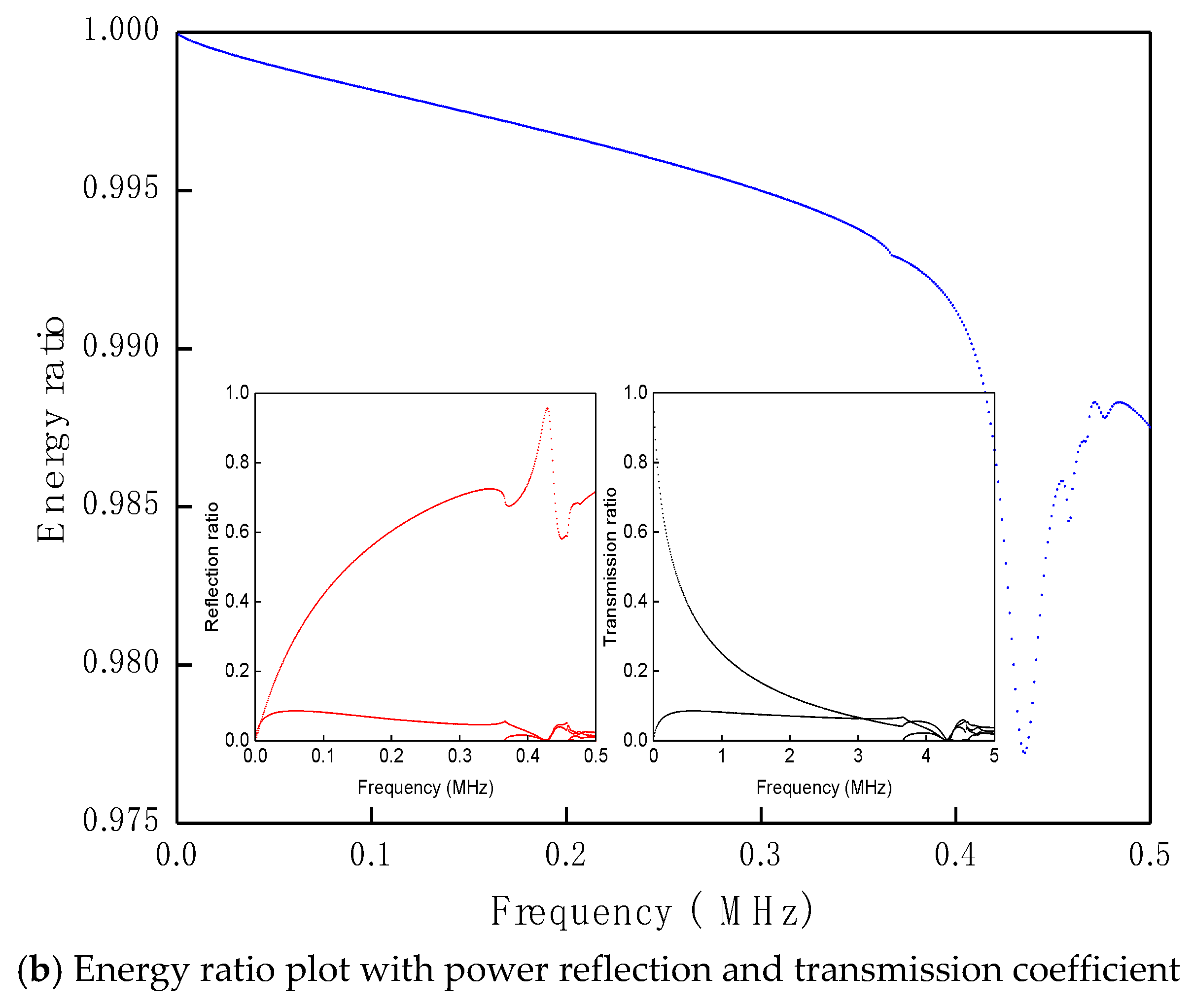
In this analysis, four kinds of groove depths (d) of 0.0, 0.5, 1.0, and 1.5R are considered, respectively, as shown in Figure 3. Also, the groove width (w) remains unchanged at 0.2R. The center of the 3D-FE area is set at 1 m, and the axial displacement, Uz at 0.5 m and 1.5 m, is calculated, respectively. The external excitation form is circular longitudinal excitation at . Its time-frequency characteristics remain consistent with Figure 1. In this section, only the damped case is discussed, where the modal expansion method is utilized. Figure 4 is the calculation results for groove depths (d) of 1.5R. It can be seen from Figure 4b that due to the existence of pitting corrosion, the original incidental wave mode has undergone a mode conversion, and there are and modes in the reflected and transmission wave, respectively. Their wave speeds can intuitively distinguish the two wave packets. The total energy of the incidental wave should be carried by all reflected and refracting waves after scattering and reflection occur. In addition to the attenuation effect of material damping on energy, the transformed new mode will share part of the energy. The original incidental wave energy will be further weakened after pitting. As the pitting depth increases, the mode component gradually decreases in the refracting wave and increases in the reflected wave.
For the newly generated mode, there are similar magnitudes at the pitting depth, and 1.5R, which can be obtained by comparing the respective energy ratio curves. The energy curve at and cut-off frequency can also be observed to decrease sharply. At this frequency, the nonhomogeneous part of the 3D-FE region transforms the original mode to other modes. It contains the high damping component at the cut-off frequency. The modal waves are attenuated when they propagate to the 3D-FE area boundary, which leads to a sudden decrease in energy. The occurrence of scattering and reflection transforms the energy into a highly damped modal component, which leads to additional energy dissipation. Figure 5 shows the axial-displacement distribution diagram of the 3D-FE region at each frequency of the damped pitting corrosion model with d = 1.0R; w = 0.2R. Thus, for analyzing the wave scattering phenomenon, a 3D-FE can simulate the damped steel wire with defects. However, in actual ultrasonic non-destructive testing, using reflected echo for diagnosis can only focus on the change of single-mode echo.
The modes that are easy to receive and have a relatively high signal-to-noise ratio have the highest energy velocity. The sudden decrease phenomenon also appears in the reflected energy ratio curves. It can be seen that different cross-sectional shapes will result in different modal transition components.
4. Conclusions
The scattering response calculation relies on the hybrid FE-SAFE method, and frequency domain analysis is used. The basic idea is to express the frequency response of the cross-section at the two ends of the 3D-FE part as a modal superposition calculated by the semi-analytical method. It can be observed from the numerical investigations on pitting corrosion and free end reflection that, without considering the material damping, the nonhomogeneous part will lead to the transition between the propagation modes. When considering material damping, this modal transition will cause additional energy dissipation. For the research of wave reflection and scattering based on the hybrid element method, the algorithm using internal DOF condensation and modal acceleration method can effectively improve the calculation efficiency. It is suitable for models with a large number of DOF in the 3D-FE area.
Funding
This research received no external funding.
Conflicts of Interest
The author declares no conflict of interest.
References
- Saravanan, T.J.; Gopalakrishnan, N.; Rao, N.P. Damage detection in structural element through propagating waves using radially weighted and factored RMS. Measurement 2015, 73, 520–538. [Google Scholar] [CrossRef]
- Saravanan, T.J.; Gopalakrishnan, N.; Rao, N.P. Detection of damage through coupled axial–flexural wave interactions in a sagged rod using the spectral finite element method. J. Vib. Control 2017, 23, 3345–3364. [Google Scholar] [CrossRef]
- Kumar, K.V.; Saravanan, T.J.; Sreekala, R.; Gopalakrishnan, N.; Mini, K.M. Structural damage detection through longitudinal wave propagation using spectral finite element method. Geomech. Eng. 2017, 12, 161–183. [Google Scholar] [CrossRef]
- Saravanan, T.J. Non-destructive testing mechanism for pre-stressed steel wire using acoustic emission monitoring. Materials 2020, 13, 5029. [Google Scholar] [CrossRef] [PubMed]
- Marzani, A.; Viola, E.; Bartoli, I.; Di Scalea, F.L.; Rizzo, P. A semi-analytical finite element formulation for modeling stress wave propagation in axisymmetric damped waveguides. J. Sound Vib. 2008, 318, 488–505. [Google Scholar] [CrossRef]
- Mazzotti, M.; Marzani, A.; Bartoli, I.; Viola, E. Guided waves dispersion analysis for prestressed viscoelastic waveguides by means of the SAFE method. Int. J. Solids Struct. 2012, 49, 2359–2372. [Google Scholar] [CrossRef]
- Saravanan, T.J. Investigation of guided wave dispersion characteristics for fundamental modes in an axisymmetric cylindrical waveguide using rooting strategy approach. Mech. Adv. Mater. Struct. 2020, 1–11. [Google Scholar] [CrossRef]
- Saravanan, T.J. Convergence study on ultrasonic guided wave propagation modes in an axisymmetric cylindrical waveguide. Mech. Adv. Mater. Struct. 2020, 1–18. [Google Scholar] [CrossRef]
- Rattanawangcharoen, N.; Shah, A.H.; Datta, S.K. Reflection of waves at the free edge of a laminated circular cylinder. J. Appl. Mech. 1994, 61, 323–329. [Google Scholar] [CrossRef]
- Taweel, H.; Dong, S.B.; Kazic, M. Wave reflection from the free end of a cylinder with an arbitrary cross-section. Int. J. Solids Struct. 2000, 37, 1701–1726. [Google Scholar] [CrossRef]
- Rattanawangcharoen, N.; Zhuang, W.; Shah, A.H.; Datta, S.K. Axisymmetric guided waves in jointed laminated cylinders. J. Eng. Mech. 1997, 123, 1020–1026. [Google Scholar] [CrossRef]
- Ahmad, Z.A.B.; Gabbert, U. Simulation of Lamb wave reflections at plate edges using the semi-analytical finite element method. Ultrasonics 2012, 52, 815–820. [Google Scholar] [CrossRef] [PubMed]
- Zhu, J.; Shah, A.H. A hybrid method for transient wave scattering by flaws in composite plates. Int. J. Solids Struct. 1997, 34, 1719–1734. [Google Scholar] [CrossRef]
- Benmeddour, F.; Treyssède, F.; Laguerre, L. Numerical modeling of guided wave interaction with non-axisymmetric cracks in elastic cylinders. Int. J. Solids Struct. 2011, 48, 764–774. [Google Scholar] [CrossRef]
- Gallezot, M.; Treyssède, F.; Laguerre, L. Numerical modelling of wave scattering by local inhomogeneities in elastic waveguides embedded into infinite media. J. Sound Vib. 2019, 443, 310–327. [Google Scholar] [CrossRef]
Figure 1.
Hybrid 3D finite element and semi-analytical finite element (FE-SAFE) model.

Figure 2.
Representation of narrow-band excitation in the spatial domain.

Figure 3.
Pitting corrosion models of steel wire for various depths.

Figure 4.
Calculation results for pitting model with d = 1.5R; w = 0.2R.


Figure 5.
3D-FE region displacement response distribution for pitting corrosion model d = 1.0R; w = 0.2R for damped waveguide (left side plot: real part; right side plot: imaginary part).
Figure 5.
3D-FE region displacement response distribution for pitting corrosion model d = 1.0R; w = 0.2R for damped waveguide (left side plot: real part; right side plot: imaginary part).


Table 1.
Material characteristics of high strength steel wire.
| Young’s Modulus, E (Mpa) | Density, ρ (kg/m3) | Poisson’s Ratio, ν | Diameter, d (mm) | Longitudinal Wave Velocity, CL (m/s) | Shear Wave Velocity, CS (m/s) |
|---|---|---|---|---|---|
| 2 × 10⁵ | 7850 | 0.3 | 5 | 5856.4 | 3130.4 |
Publisher’s Note: MDPI stays neutral with regard to jurisdictional claims in published maps and institutional affiliations. |
© 2020 by the author. Licensee MDPI, Basel, Switzerland. This article is an open access article distributed under the terms and conditions of the Creative Commons Attribution (CC BY) license (https://creativecommons.org/licenses/by/4.0/).
Share and Cite
MDPI and ACS Style
Thiyagarajan, J.S. Investigation of Guided Wave Interaction with Discontinuities in the Axisymmetric Damped Waveguide. Proceedings 2020, 67, 12. https://0-doi-org.brum.beds.ac.uk/10.3390/ASEC2020-07539
AMA Style
Thiyagarajan JS. Investigation of Guided Wave Interaction with Discontinuities in the Axisymmetric Damped Waveguide. Proceedings. 2020; 67(1):12. https://0-doi-org.brum.beds.ac.uk/10.3390/ASEC2020-07539
Chicago/Turabian StyleThiyagarajan, Jothi Saravanan. 2020. "Investigation of Guided Wave Interaction with Discontinuities in the Axisymmetric Damped Waveguide" Proceedings 67, no. 1: 12. https://0-doi-org.brum.beds.ac.uk/10.3390/ASEC2020-07539