Effect of Mechanical Loading and Increased Gap on the Dynamic Response of Multiple Degree of Freedom Electrostatic Actuator †

Mechanical and Medical Engineering Department, Furtwangen University, Robert-Gerwig-Platz 1, 78120 Furtwangen, Germany
†
Presented at the First International Electronic Conference on Actuator Technology: Materials, Devices and Applications, 23–27 November 2020; Available online: https://iecat2020.sciforum.net/.
Proceedings 2020, 64(1), 18; https://0-doi-org.brum.beds.ac.uk/10.3390/IeCAT2020-08498
Published: 20 November 2020
(This article belongs to the Proceedings of The 1st International Electronic Conference on Actuator Technology: Materials, Devices and Applications)
Abstract
:A novel monolithic structural design of an electrostatic actuator with a multiple degree of freedom is presented as an approach for a system that is capable of performing scalable stroke and large electrostatic force beyond mN range. An electromechanical system model based on Simulink software was developed for a proposed design of the electrostatic actuator. The dynamic response of the actuator was simulated and the mechanical bouncing response due to effect of realizing extra mechanical stoppers or passivation layer was investigated. Additionally, the mechanical bouncing as well as steady state response of the actuator was investigated under various mechanical loading values. The results showed that the switching time increased as the mechanical load was increased. In addition, bouncing maximum peak increased as the collision force was increased.
1. Introduction
Electrostatic inchworm motor based on gap-closing variable capacitor provides a potential solution for larger force actuation compared to an area overlapping one. Unlike the constant electrostatic force in area overlapping variable capacitor, the generated electrostatic force in the gap-closing variable capacitor increases as the displacement is increased. However, due to the pull-in phenomena the system stability and controllability are critical design challenges.
Various designs of complex electrostatic actuators based on a gap-closing variable capacitor were developed as a linear inchworm motor [1,2,3,4]. However, the force actuation capability is still in mN range. In [1] the electrostatic inchworm consists of four microactuators, two for holding function and two for twisting function. The inchworm is capable of performing a 100 nm step displacement against 0.12 mN load, when the corresponding voltage gate is polarized at 15 V. In [2] a displacement amplification mechanism was employed in the electrostatic inchworm design. A stroke of 35 µm against 0.11 mN load was achieved, providing that actuator was electrically polarized at 16 V. In [3] a shuttle with a flexible arm design was implemented as an electrostatic inchworm. The device performed a stroke of 10 µm against 1.88 mN, when it was electrically polarized at 110 V. Higher load forces up to 3.7 mN could be measured, however snapping failure was observed. In [4] an optimized shuttle design compared to the one in [3] was realized. The new device could perform a 1 µm stroke against 1.3 mN, when it was electrically polarized at 60 V.
In this paper, a novel monolithic structural design of electrostatic actuator with a multiple degree of freedom is presented as an approach for a system that is capable of performing scalable stroke and large electrostatic force beyond mN range. The actuator is a kind of mechanical oscillator which can be driven in the xy-directions by three voltage electrodes. Multiple actuators can be used to increase the overall applied electrostatic force.
2. Methods
2.1. Structural Design and Operation Concept
The top view of the electrostatic actuator is shown in Figure 1. The actuator consists mainly of a mechanical oscillator and voltage electrodes. The mechanical oscillator is the square shape frame, suspended by mechanical springs with an anchor at the center. The frame is designed to be movable in the in-plane directions. Mechanical stoppers are used to limit the deflection distance in the in-plane directions. The limit is designed such that the frame does not collide with the fixed electrodes, which is called here the actuation gate. The mechanical oscillator with the actuation gates represent three variable capacitors, where the frame represents the movable electrode, while the actuation gate is the fixed electrode. The mechanical oscillator is electrically actuated by the lateral and vertical actuation gates. The frame itself is connected to ground through the anchor, while the actuation gate is connected to a specific voltage value. For example, when the potential voltage is applied at the vertical actuation gate, while other actuation gates as well as the anchor are connected to ground, then electrostatic force will be generated causing the frame to be deflected toward the vertical actuation electrode. A comb structure called integrated shaft is a movable mechanical element used for actuating the external mechanical load. The interdigitated shaft is initially integrated with another fixed comb structure called stationary holder. The interdigitated shaft is also actuated based on electrostatic force by implementing extra voltage electrode, such that the shaft can be released from the stationary holder, but simultaneously overlapped with the comb structure of the lower part of the frame. In this case, the shaft can be deflected laterally in both directions, and therefore actuating the external mechanical load.
2.2. Mathematical Modelling and Simulink Model
The mathematical equations of the electrostatic device in Figure 1 are extracted based on Newton’s second law. These equations will be used then to implement a Simulink model for the simulation. Here, only the mechanical oscillator, mechanical stoppers and actuation electrodes are considered for the modelling. The mechanical oscillator consists of mass (m) realized by the frame and folded beams suspension, elastic elements of stiffness constant (k) realized by the folded beams suspension. The mechanical stoppers can be represented as elastic elements with an extremely large stiffness constant (ks). The effect of mechanical stopper will take place once the frame approaches the mechanical stopper. The dielectric medium between the frame and actuation gates affects the response of the mechanical oscillator through the viscosity damping effect. Here, a vacuum with arbitrary damping coefficient (b) is applied. Only the lateral deflection response will be studied. Therefore, the internal net force (Fint) of the mechanical oscillator can be represented in terms of mass acceleration (a), velocity (v), deflection (x) by the following equation:
the parameters xs1 and xs2 are deflection limits in the left and right sides of the frame. The mechanical oscillator is electrically excited by the actuation electrodes, at which electrostatic forces are generated. The lateral deflection of the frame implies a gap closing capacitance variation. Therefore, the external excitation force (Fext) can be given by the following equation:
the equation above represents the net electrostatic force of the right and left actuation electrodes subtracted from the external mechanical load (FL). The equation is extracted in terms of applied voltage (V), deflection (x), initial gap (G) and instantaneous capacitance (C), which are given by:
the capacitance equations are represented in terms of vacuum electric permittivity (εo), dielectric constant (εr), electrode length (L), electrode height (H).
The mathematical model was implemented as a Simulink block diagram in Figure 2. The model was simulated with m = 4 µg, k = 34 kN/m, kS = 34 × 1012 N/m, b = 0.1 N·s/m, L = 250 µm, H = 50 µm, GC = 4.5 µm and GS = 2.5 µm. For these values the pull-in voltage is 2.88 kV. The model contains specific function blocks for determining the instant of mechanical impact with the mechanical stopper and the external mechanical force. In the simulation only one actuation gate VC2 was activated at 10 KV step signal.
3. Results and Discussion
3.1. Effect of Mechanical Stoppers and External Mechanical Loading
In this simulation the deflection limit due to mechanical stoppers was designed at 2.5 µm. The external mechanical force was initially set 2 µm apart from the actuator. The dynamic response of the actuator was then extracted for various external mechanical loading, from no load, up to 2.4 N (Figure 3). Mechanical bouncing and mechanical damping are the main observations in this result. The mechanical bouncing maximum peak decreases as the counter mechanical loading value increases. For example, at no load was the bouncing maximum peak 112.5 nm, while it was 25 nm at 0.9 N load. Such a bouncing response will cause an actuation stability problem if the electrodes of the comb structures are included in the model. The bouncing maximum peaks will influence the design of the gap between electrodes of the comb structures.
Bouncing responses also exhibited different slopes, such that the larger the mechanical load, the less the slope of displacement response. This decreased slope means that the mass velocity as well as kinetic energy is decreasing with increased mechanical load, thus a lower collision effect appeared as a lower bouncing peak. The application of counter electrostatic force through the other variable capacitor (C1) will be a potential approach to reduce the bouncing effect, and therefore enhancing the actuation stability of the actuator.
The maximum displacement of 2.5 μm was achieved between 0 and 0.9 N mechanical load. At 1 N load the actuator performed for a specific time further displacement before it started returning back to the 2 μm position at which the mechanical load was initially set. At the instant of load impact, the net excitation force, electrostatic and load forces decrease abruptly, thus both acceleration and velocity decrease too. When the velocity becomes zero, the mechanical load force dominates the excitation force such that the displacement starts decreasing. At this moment, the resultant electrostatic force decreases too. The final state is that at which the actuator bounces with extremely small peaks around the 2 μm position.
In terms of bouncing transient time, a value of 900 msec was roughly the same for mechanical load between 0 and 0.9 N. For a larger loading than the 0.9 N, the bouncing transient time was between 0.8 and 1.2 sec. The bouncing transient time will influence the design of the switching signal of the actuator.
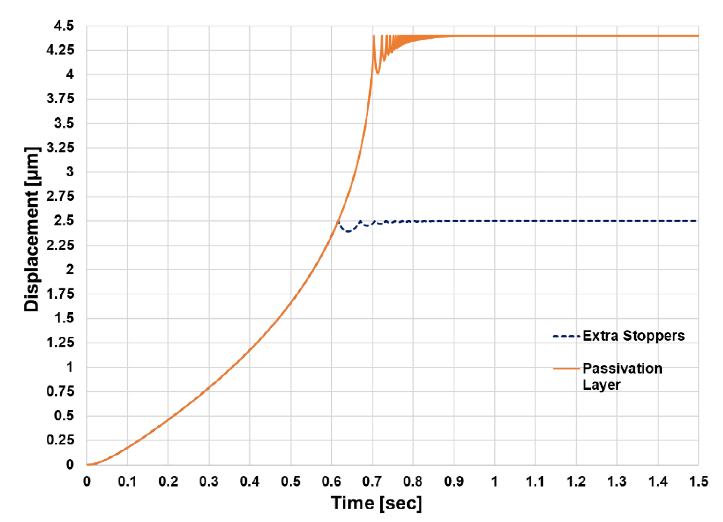
3.2. Dynamic Response Under Increased Gap Design
In this simulation, the mechanical stoppers were removed from the design. An electrical insulation layer passivation of 100 nm on the fixed electrode of the variable capacitor was considered. This design allows a larger travelling response (Figure 4). The response was obtained under no mechanical loading. The mechanical bouncing maximum peak increased from 112.5 nm to 400 nm compared to the case of applying extra mechanical stoppers. The larger electrostatic force is the larger corresponding actuation force. However, more impact of mechanical bouncing was observed. This trade-off result will affect the design of the comb structures for the clutching.
4. Conclusions
In this work, the effect of mechanical bouncing and mechanical damping due to mechanical collisions of the electrostatic actuator was studied by means of an electromechanical Simulink model. The variation of applied mechanical load affects the resultant bouncing maximum peak, such that the larger the mechanical load the less the bouncing maximum peak. On the other hand, the displacement slope response decreases as the applied mechanical load is increased. These findings critically affect the design of electrodes of comb structures for clutching and the design of switching signal. The application of a complementary variable capacitor will be a potential approach to reduce the bouncing effect, and thereby enhancing the actuation stability of the actuator.
Acknowledgments
This project is funded by the German Research Foundation (DFG) under the umbrella of the priority programm SPP 2206—KOMMMA (Cooperative Multistage Multistable Micro Actuator Systems).
Conflicts of Interest
The founding sponsors had no role in the design of the study, in the collection, analyses, or interpretation of data; in the writing of the manuscript, and in the decision to publish the results.
References
- Kim, S.-H.; Hwang, I.-H.; Jo, K.-W.; Yoon, E.-S.; Lee, J.-H. High resolution inchworm linear motor based on electrostatic twisting microactuators. J. Micromech. Microeng. 2005, 15, 1674–1682. [Google Scholar] [CrossRef]
- Erismis, M.A.; Neves, H.P.; Puers, R.; Hoof, C.V. A low voltage large displacement large force inchworm actuator. JMEMS 2008, 17, 1294–1301. [Google Scholar] [CrossRef]
- Penskiy, I.; Bergbreiter, S. Optimized electrostatic inchworm motors using a flexible driving arm. J. Micromech. Microeng. 2013, 23, 015018. [Google Scholar] [CrossRef]
- Saito, K.; Contreras, D.S.; Takeshiro, Y.; Okamoto, Y.; Hirao, S.; Nakata, Y.; Tanaka, T.; Kawamura, S.; Kaneko, M.; Uchikoba, F.; et al. Study on electrostatic inchworm motor device for a heterogeneous integrated microrobot system. Trans. Jpn. Inst. Electron. Packag. 2019, 12. [Google Scholar] [CrossRef]
Figure 1.
Top view of multiple degree of freedom electrostatic actuator design.

Figure 2.
Simulink model of the multiple degree of freedom electrostatic actuator.

Figure 3.
Dynamic response of electrostatic actuator under different mechanical loading values.

Figure 4.
Dynamic response of electrostatic actuator under different limiting positions.

Publisher’s Note: MDPI stays neutral with regard to jurisdictional claims in published maps and institutional affiliations. |
© 2020 by the author. Licensee MDPI, Basel, Switzerland. This article is an open access article distributed under the terms and conditions of the Creative Commons Attribution (CC BY) license (https://creativecommons.org/licenses/by/4.0/).
Share and Cite
MDPI and ACS Style
Kloub, H. Effect of Mechanical Loading and Increased Gap on the Dynamic Response of Multiple Degree of Freedom Electrostatic Actuator. Proceedings 2020, 64, 18. https://0-doi-org.brum.beds.ac.uk/10.3390/IeCAT2020-08498
AMA Style
Kloub H. Effect of Mechanical Loading and Increased Gap on the Dynamic Response of Multiple Degree of Freedom Electrostatic Actuator. Proceedings. 2020; 64(1):18. https://0-doi-org.brum.beds.ac.uk/10.3390/IeCAT2020-08498
Chicago/Turabian StyleKloub, Hussam. 2020. "Effect of Mechanical Loading and Increased Gap on the Dynamic Response of Multiple Degree of Freedom Electrostatic Actuator" Proceedings 64, no. 1: 18. https://0-doi-org.brum.beds.ac.uk/10.3390/IeCAT2020-08498