
Design Optimization of Interfacing Attachments for the Deployable Wing of an Unmanned Re-Entry Vehicle


CIRA—Italian Aerospace Research Centre, Via Maiorise snc, 81043 Capua, Italy
*
Author to whom correspondence should be addressed.
Algorithms 2021, 14(5), 141; https://0-doi-org.brum.beds.ac.uk/10.3390/a14050141
Submission received: 10 April 2021
/
Revised: 25 April 2021
/
Accepted: 27 April 2021
/
Published: 28 April 2021
(This article belongs to the Special Issue Algorithms and Models for Dynamic Multiple Criteria Decision Making)
Abstract
:Re-entry winged body vehicles have several advantages w.r.t capsules, such as maneuverability and controlled landing opportunity. On the other hand, they show an increment in design level complexity, especially from an aerodynamic, aero-thermodynamic, and structural point of view, and in the difficulties of housing in operative existing launchers. In this framework, the idea of designing unmanned vehicles equipped with deployable wings for suborbital flight was born. This work details a preliminary study for identifying the best configuration for the hinge system aimed at the in-orbit deployment of an unmanned re-entry vehicle’s wings. In particular, the adopted optimization methodology is described. The adopted approach uses a genetic algorithm available in commercial software in conjunction with fully parametric models created in FEM environments and, in particular, it can optimize the hinge position considering both the deployed and folded configuration. The results identify the best hinge configuration that minimizes interface loads, thus, realizing a lighter and more efficient deployment system. Indeed, for such a category of vehicle, it is mandatory to reduce the structural mass, as much as possible in order to increase the payload and reduce service costs.
Keywords:
design optimization; genetic algorithms; re-entry vehicle; space; USV3; deployable wing; FEM1. Introduction
The Italian Aerospace Research Centre (CIRA) is involved in several programs to develop new technologies, material, and structural concepts to speed up the process of designing and manufacturing the next European System for in-orbit-experimentation with re-entry capability, known as Space Rider, after the successful heritage of the IXV program [1,2].
For such vehicles, one of the key points is the need for a hot primary structure that can withstand the severe thermo-structural challenges that are typical of the re-entry phase aero-thermal environment. Ceramic matrix composites (CMC) are widely used and have been developed for this purpose in the last few decades [3,4,5,6]. CIRA is also developing new CMC for space applications, for the design of control surfaces and thermal protection systems [7,8,9]. Another key point is represented by the development of key technologies applicable to future unmanned spacecraft, for re-entry from LEO orbits w.r.t structural optimization. In this framework, CIRA was the primary contractor on the Unmanned Space Vehicle 3 project, named USV3 [10].
The CIRA Unmanned Space Vehicle (USV3) concept must respect a set of technical guidelines, in particular, the objective is to perform an autonomous orbital and suborbital flight, with enhanced flying capability and conventional landing on a runway.
A typical atmospheric re-entry flight consists of three phases: a hypersonic phase, a transition phase from supersonic to subsonic flight, and a landing phase. During the hypersonic phase, aero-braking decelerates the vehicle from near-orbital velocity while cross-range maneuvering and down-range energy management are used to reach the desired landing area. The transition phase requires only stable, controllable flight. The landing phase consists of intercepting the approach path, and holding an established glide slope with the correct excess speed to enable a flare maneuver for landing.
The selected aerodynamic shape is based on a winged body concept [11,12]. The advantages of using a winged body that relies on improved low-speed flight, landing performance, and hypersonic maneuverability must be weighed against the complexity of the design by aerodynamics, aerothermodynamics, and structural point of view. Moreover, the need for housing in operative existing launchers, such as the VEGA-C fairing of a winged vehicle, leads to the adoption of very stretched vehicle configurations, with consequent penalties in terms of volume and weight to be dedicated to the payload. Therefore, a deployable wing solution could overcome difficulties in the launcher accommodation offering, at the same time, the opportunity to keep the winged layout [13].
The “USV3 DWS” is a 2500 kg re-entry vehicle, equipped with deployable wings housed in the fairing of the VEGA C launcher.
The vehicle conceptual design equipped with a deployable wing is the output of a trade-off study (phase 0/A study, ECSS standard) that aimed to define a possible system concept design and related high-level system requirements, taking into account the following criteria: global weight minimization; payload maximization; optimization of aerodynamic efficiency over all the flight regimes; mass minimization of wing thermal shields; maximization of mechanisms simplicity and reliability.
In particular, two different concepts, each one with a different re-entry strategy, have been identified by exploiting the experience acquired during USV1, USV3, and IXV programs and the ongoing activity on the Space Rider European program.
The first concept (IXV-based) is expected to operate a re-entry mission based on the following three phases: atmospheric re-entry without wing (lifting body) and controlled flight up to the low supersonic or transonic regime; deceleration using a parachute (if needed) and deployment of the wing; controlled flight through transonic and subsonic regimes up to landing.
The second concept (USV3-based) is designed to operate a re-entry mission performing a wing deployment prior to the atmospheric re-entry and to operate all the aerodynamic regimes with a “winged” configuration.
In terms of the deployment mechanism, the first concept is, of course, more demanding due to the fact that the deployment happens in the atmosphere and, therefore, the actuation system can withstand the aerodynamic forces and be quickly performed to guarantee a significant synchronization level in the wings deployment. Further, some mechanism components would be exposed to the space environment during the orbital phase. These issues are avoided for the second concept, because the wing releasing phase occurs at the beginning of the orbital phase. On the other hand, the mechanism components of the second concept shall be designed considering the presence, on the wing, of a significant thermal protection system (TPS) layer, reducing the available clearance for mechanism housing.
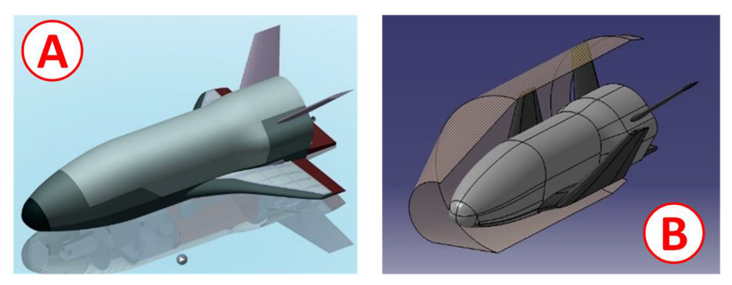
By means of the trade-off analysis, a configuration based on the wing deployment at the beginning of the orbit phase was defined as the best one. Figure 1 shows the selected configuration (identified as USV3 “WB-B3”) in operative condition (deployed wings) and in stored configuration inside the schematic VEGA-C fairing (folded wings). The entire CAD model was developed using CATIA V5-6R2016.
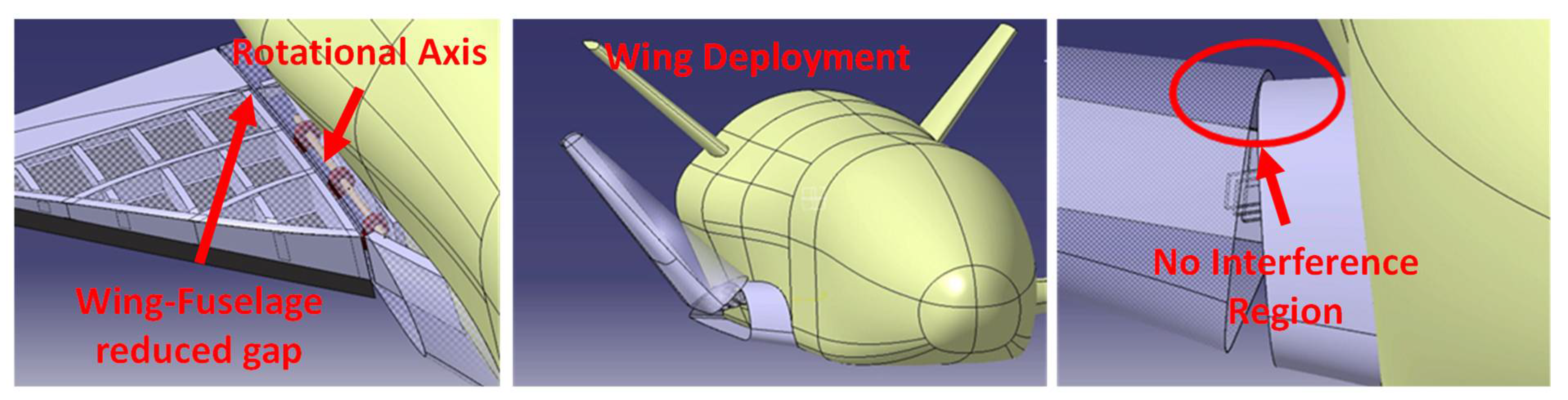
The deployable wing system (DWS) guarantees the connection between the fuselage cold structure and the deployable wing structure and is basically composed of the actuation system and at least two hinges, the shape of which has been conceived to ensure a stable and strong connection both in the folded and deployed configuration.
The position of the DWS rotation axis has been defined considering the need to minimize the portion of fixed wing, to minimize the gap between the fixed wing portion and deployable wing, and to avoid any interference during wing deployment as shown in Figure 2.
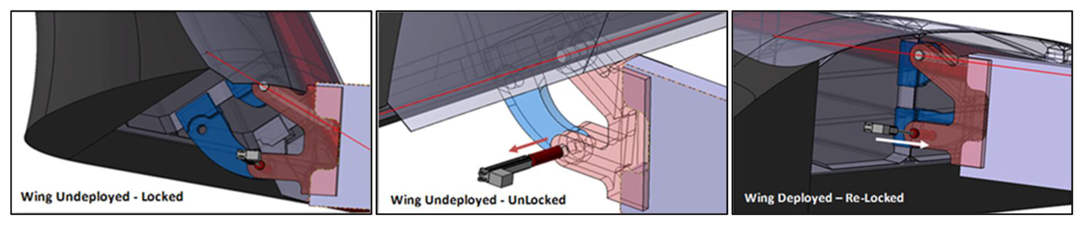
The locking subsystem concept is basically made up of a set of pins moved by a linear actuator that has the purpose of retracting the pin (release function) before the deploying phase, and re-inserting the pins into their seats when the deployment phase is completed (Figure 3).
A set of main preliminary requirements (summarized in Table 1) has been defined as the input for performing a trade-off study to define the best position of the DWS hinges.
The proposed work presents a positioning study of the hinges that enable the deployment of the wing of the USV3 DWS. The results of the optimization process adopted to evaluate the best configuration for the hinges are shown below. The critical parameters are the interface forces generated both in the unfolded and folded configuration; therefore, the analyses aimed to identify the optimal position in terms of the minimization of these forces. These results are the input data and represent the general requirements for the design of the deployment system (DWS). The position of the right hinge can reduce the applied loads as much as possible, leading to a component with a reduced mass (key aspect for space application).
2. Problem Description
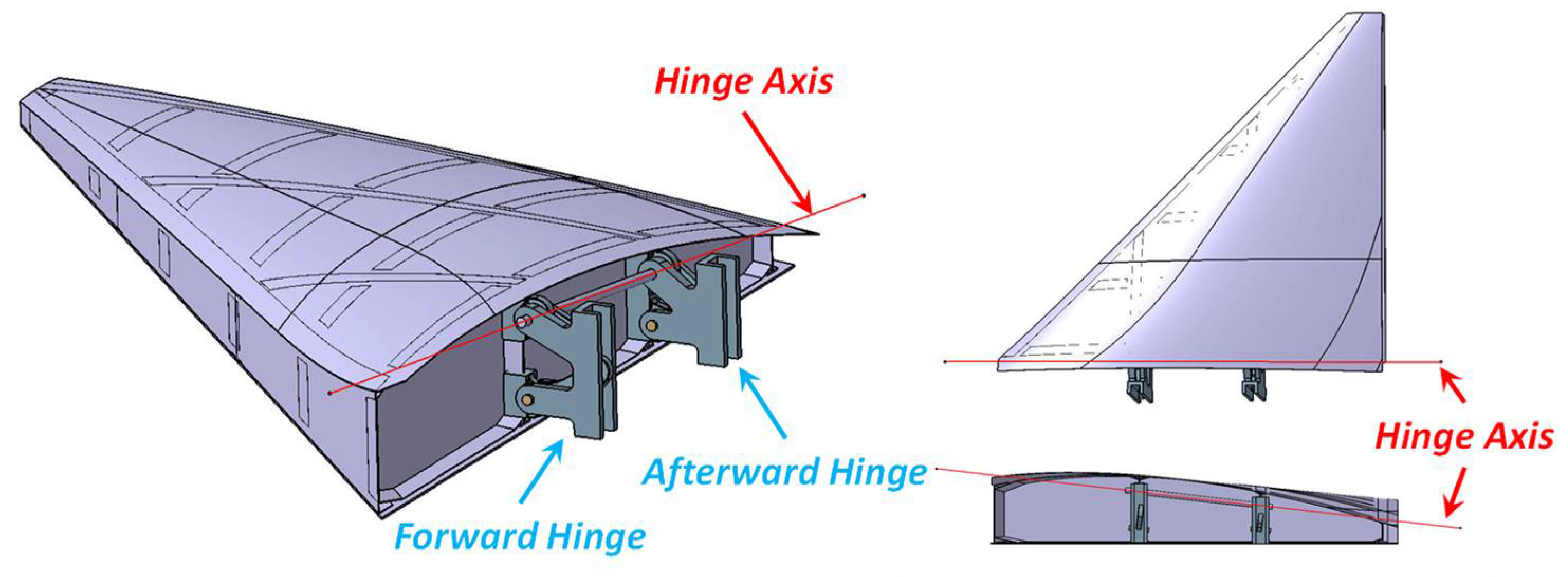
Figure 4 shows the CAD model of the structural parts of the USV3 vehicle wing (therefore, without the TPS). The same figure reports both the wing’s rotational axis and the starting position of the hinges derived from the structural architecture of the reference vehicles (IXV, USV), and, in particular, their position is related to the position of the main frames. With the development of USV3, however, with the introduced complication of a deployable wing, the possibilities of preserving the total mass requirement (Table 1) could be put at risk (obviously, the deployment system results in an increment of parts number). For this reason, dedicated structural optimization analyses are needed. Interface load reduction, which could be derived from better hinge positioning, is one of the primary concerns for obtaining lighter components.
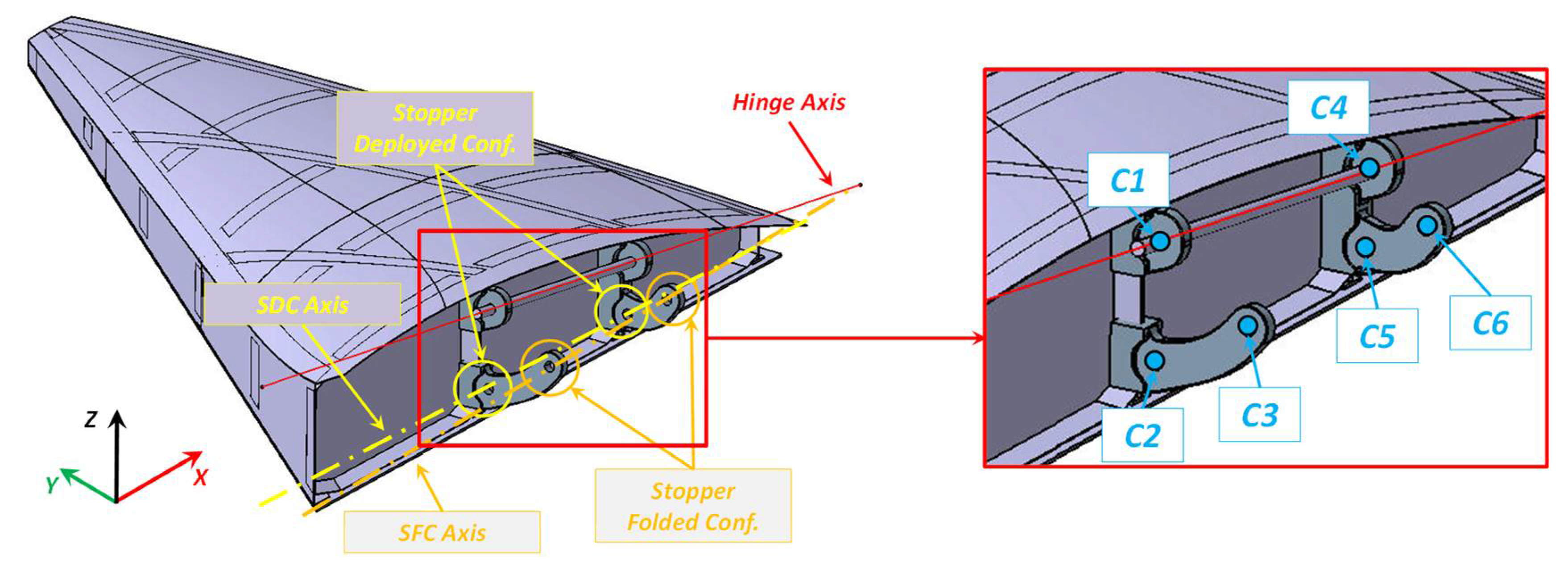
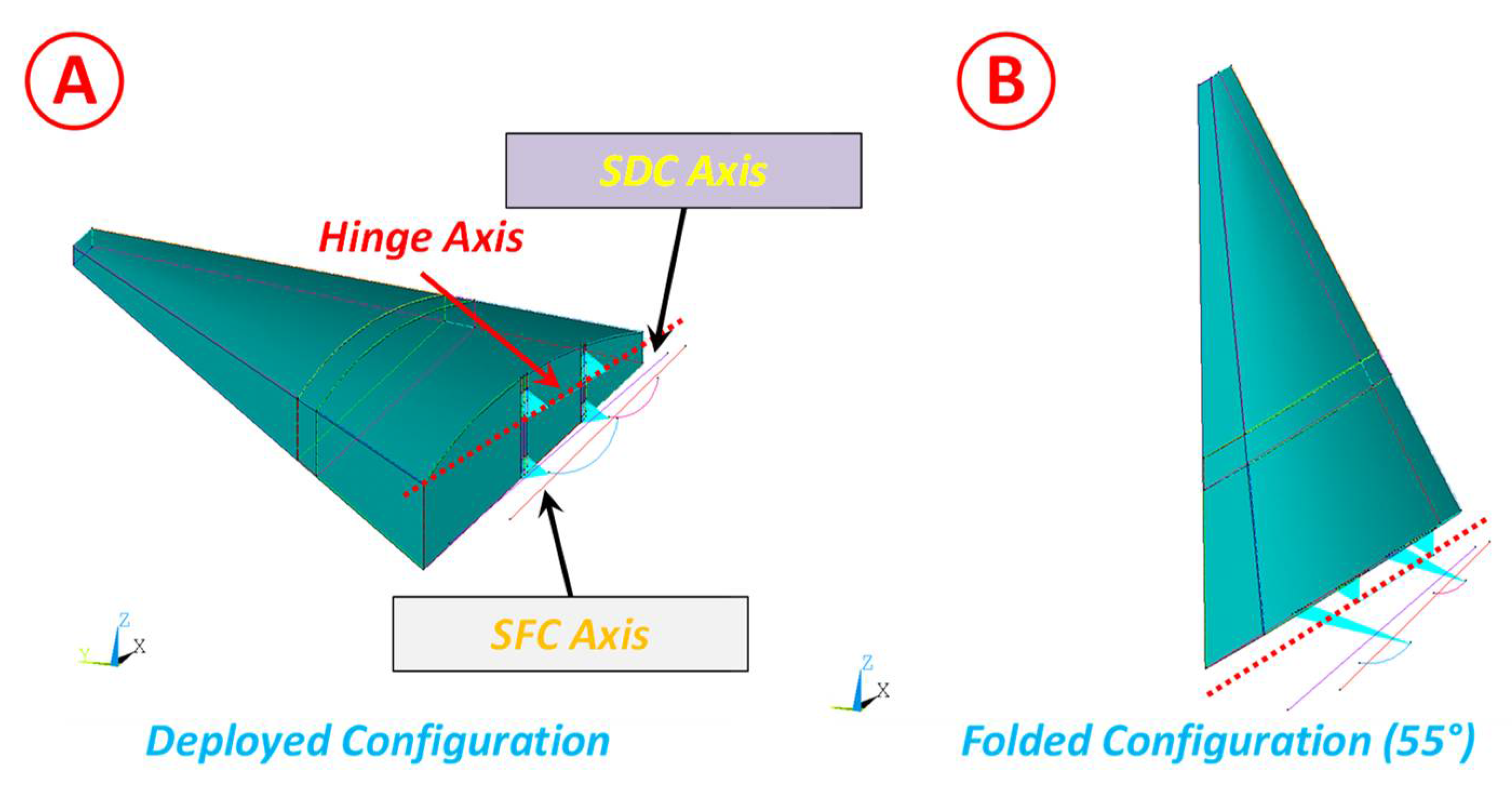
The DW connection system consists of two hinges, which will be referred to as the forward hinge (FRW-H) and afterward hinge (AFT-H). The wing rotates around the axis shown in Figure 4 and Figure 5 (Hinge Axis) and is kept in the deployed position by a pair of pins that engage in two holes (stopper deployed configuration) placed on the stopper deployed axis (SDC Axis). While the wing is kept in the folded position with a similar system that involves another couple of holes (stopper folded configuration) placed along the stopper folded axis (SFC Axis).
Figure 5 shows the three fundamental axes for evaluating the best position of the hinges. The hinge axis, lying on the XZ plane, is an input data and, therefore, it cannot be modified since its position enables the rotating of the wing without any interferences w.r.t the fuselage structures. The other two axes are instead determined by the architecture of the hinges. In particular, the stopper axis in the unfolded configuration lies in the XZ plane (vehicle axes) and its inclination, around the Y axis, is a function of the hinge axis distance at the FRW and AFT stations. The stopper axis in the folded configuration is finally determined by rotating the axis of the unfolded stopper of the closing angle, which is 55°, around the hinge axis.
Therefore, the hinges are able to slide along these axes in both directions. The three axes are not parallel to each other, and, for this reason, the projections of the hole centers of each hinge (FRW-H and AFT-H) will not lie in the same ZY plane (vehicle reference system). The parametric FE model (described in the next section) can control these misalignments accurately and, therefore, determine the station along the X axis of the center of each hole.
Figure 5 shows the centers of the holes that are used to evaluate the reaction forces and are used to accommodate the rotation axes and locking pins.
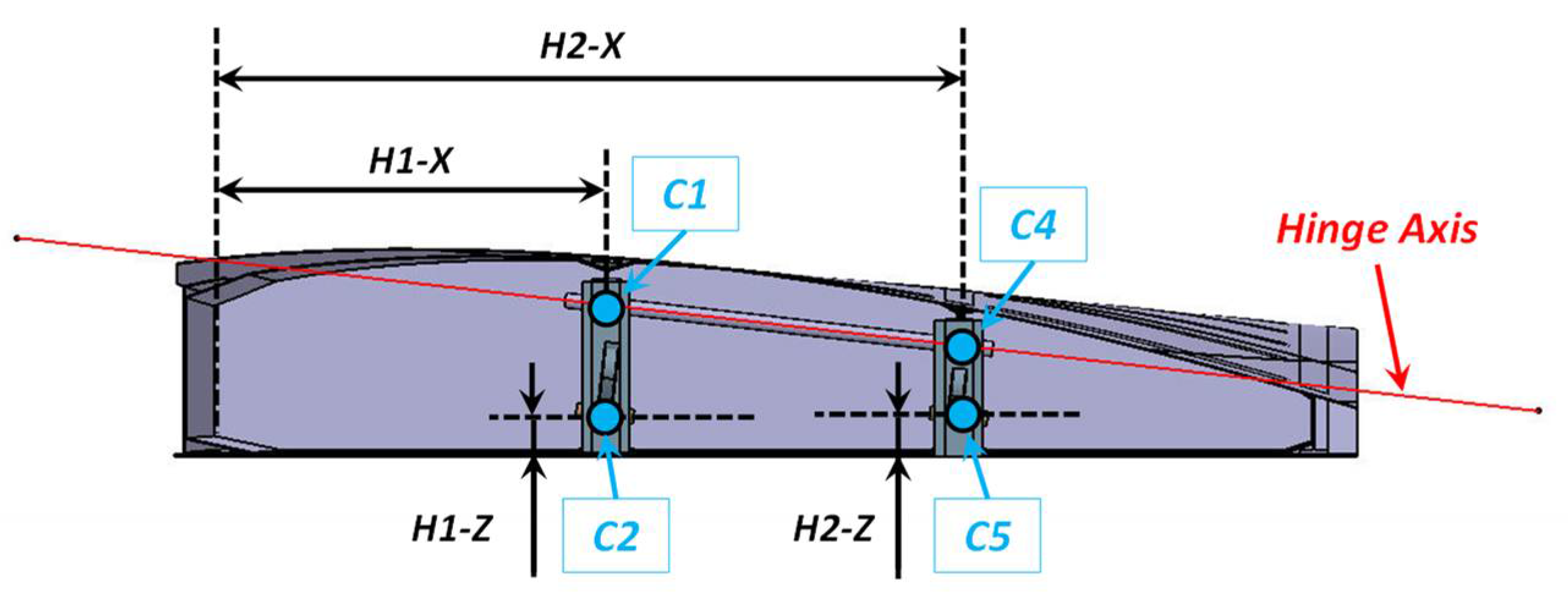
Definition of Design Variables
The hinge location is defined by means of four parameters that represent the design variables. They are the position, along the X-axis, of points C1 and C4 and the position, along the Z-axis, of points C2 and C5, as reported in Figure 6. Points C3 and C6 are automatically determined by defining the wing rotation angle by a rigid rotation of C2 and C5 points around the hinge axis (Figure 5). Within the developed APDL macro, appropriate relationships are defined between the positions of the six points in order to ensure the consistency of the models. For example, mathematical relations are inserted on the positions in X in order to guarantee that the forward hinge will always be in advanced position w.r.t the afterward one.
The stopper axis, in the deployed configuration, is parallel to the X axis of the global model by setting H1-Z = H2-Z. This assumption will be held to satisfy functional requirements.
3. Model Description
To study the optimal configuration for the hinge system, a simplified parametric model of the wing was developed. Both the model and the whole set of analyses were carried out in the ANSYS environment. The parametric model was created by means of a dedicated routine developed using APDL language [15] (Ansys Parametric Design Language).
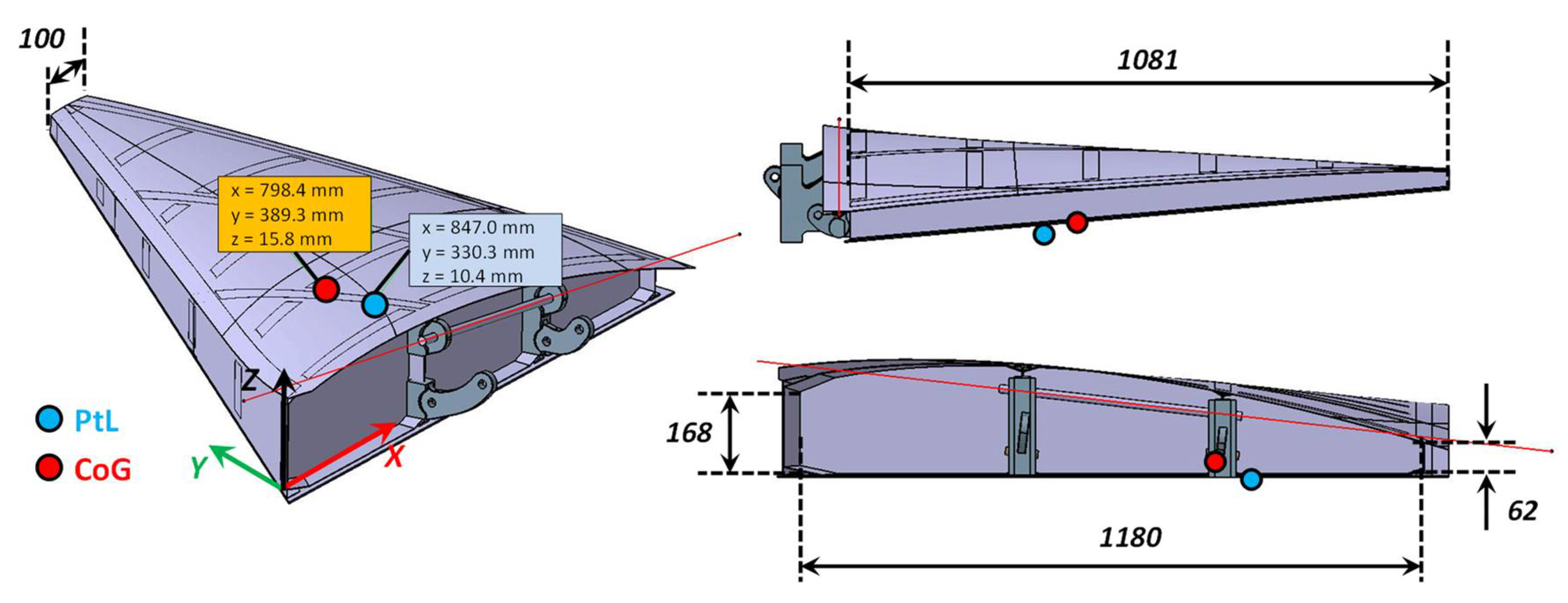
The numerical model was defined considering the main geometric dimensions and, in particular, the two points where the load was applied, i.e., the center of gravity (CoG) and the point where it is possible to concentrate the aerodynamic loads (PtL).
Figure 7 shows, schematically, the global dimensions and the location of the CoG and PtL. The estimated overall mass of the wing is 92.15 kg (including the TPS and the installed sub-systems). The rational angle in the folded configuration is 55°.
Figure 8 shows the simplified numerical model. The hinges were not modeled directly but by means of rigid elements, as direct modeling of the hinges is not entirely relevant for the evaluation of reaction loads. Furthermore, this choice reduces the computational costs, which is a relevant issue for the optimization analysis.
Hinge reaction forces are evaluated for both configurations: deployed and folded wing (55°). The routine is designed to analyze both configurations by properly rotating the wing (Figure 8).
Even if a full FE model is not mandatory for such evaluations (as the rigid model was used), it was adopted to have a better understanding of the analyzed configurations and to simplify the constraints definition. Indeed, the location of the holes could be determined by geometrical/mathematical relationships and the reaction forces could be determined by solving the equation system related to a hyper-static structure. On the other hand, using an analytical formulation would introduce some approximations in order to simplify the equations and it would not provide the capability to define the exact location of the holes (the position of the stopper holes in the folded configuration depend on the other four holes and by their specific station along the chord direction. Further, C1, C2, and C3 do not lie in the same plane, nor do C4, C5, and C6).
Furthermore, the choice to adopt an FE model, instead of analytical formulations, is also justified by the very small computational costs related to such an FE model. Indeed, a single run, which consists of a model generation and two static analyses with two post-processes, requires at most 15 s on an HP Z840 Workstation–Intel Xeon CPU E5-2620 v3 @ 2.40 GHz; RAM 128 GB.
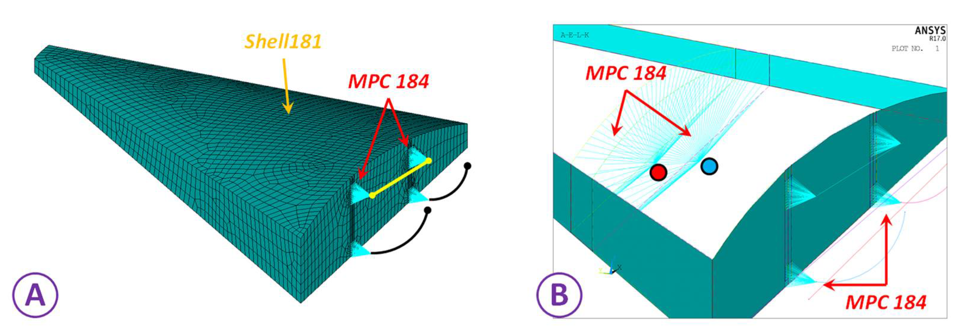
The outer surface of the wing has been discretized with shell elements (Shell181) that have been assigned a rigid behavior (Figure 9A). The load application points, both for the unfolded and folded configuration, are connected to the main structure by rigid elements (MPC184). The centers of the holes of the deploying system are connected to the root rib by rigid elements (MPC184) as shown in Figure 9B. The whole FE model consists of about 4000 elements (3600 shells and 400 MPCs) and about 3500 nodes. As rigid behavior has been adopted for the wing, the average element size (25 mm far from the region of the hinges and 5 mm close to them) aims to reproduce the wing shape with a discrete accuracy and to have good force distribution (both applied loads and reaction forces), but this is not a critical aspect.
Boundary Conditions
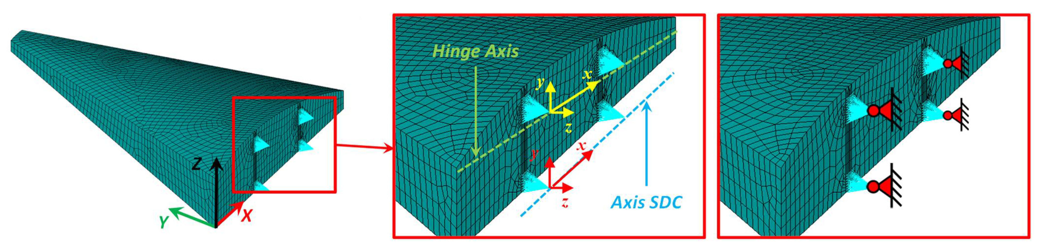
The wing structure is constrained at the centers of the holes of both components of each hinge. The centers of these holes lie on one of the three defined axes (hinge axis, stopper axis in unfolded configuration, and stopper axis in the folded configuration).
The reference points of the rigid elements are constrained in translation degrees of freedom w.r.t local reference systems where the X axis is parallel to the specific axis on which the point lies, as reported in Figure 10 for the deployed configuration. The same condition was applied for both the unfolded and folded configuration. Figure 10 schematically shows the boundary conditions that were applied.
The applied loading conditions are different between unfolded and folded configuration. In the deployed configuration the load, equal to 13.6 kN, acts along the Z direction, and it has been applied in the pressure center, i.e., PtL. When the wing is in the folded configuration, it is in the fairing of VEGA-C, and, therefore, the load derives from the acceleration field generated by the launch phase and it can be schematically applied at the center of gravity of the wing (CoG). The acceleration factor is 7.5 g along a longitudinal direction (X axis) and 1.35 g along lateral directions (Z and Y axes), as reported in Table 1.
4. Optimization Analysis
To evaluate the optimal hinge configuration, optimization analysis has been performed by fusing the commercial ModeFrontier code [16] that is an integration platform for multi-objective and multi-disciplinary optimization. It provides an easy coupling method with third-party engineering tools (like Finite Element codes), enables the automation of the design simulation process, and facilitates analytic decision making.
A multidisciplinary approach is key for a successful design process, especially when the constraints and the requirements are very challenging. A powerful workflow enables the execution of complex chains of design optimization and innovative algorithms to determine the set of best possible solutions that combine opposing objectives.
The code is widely used in engineering applications and is demonstrated to be suitable for several technical problems [17,18,19,20].
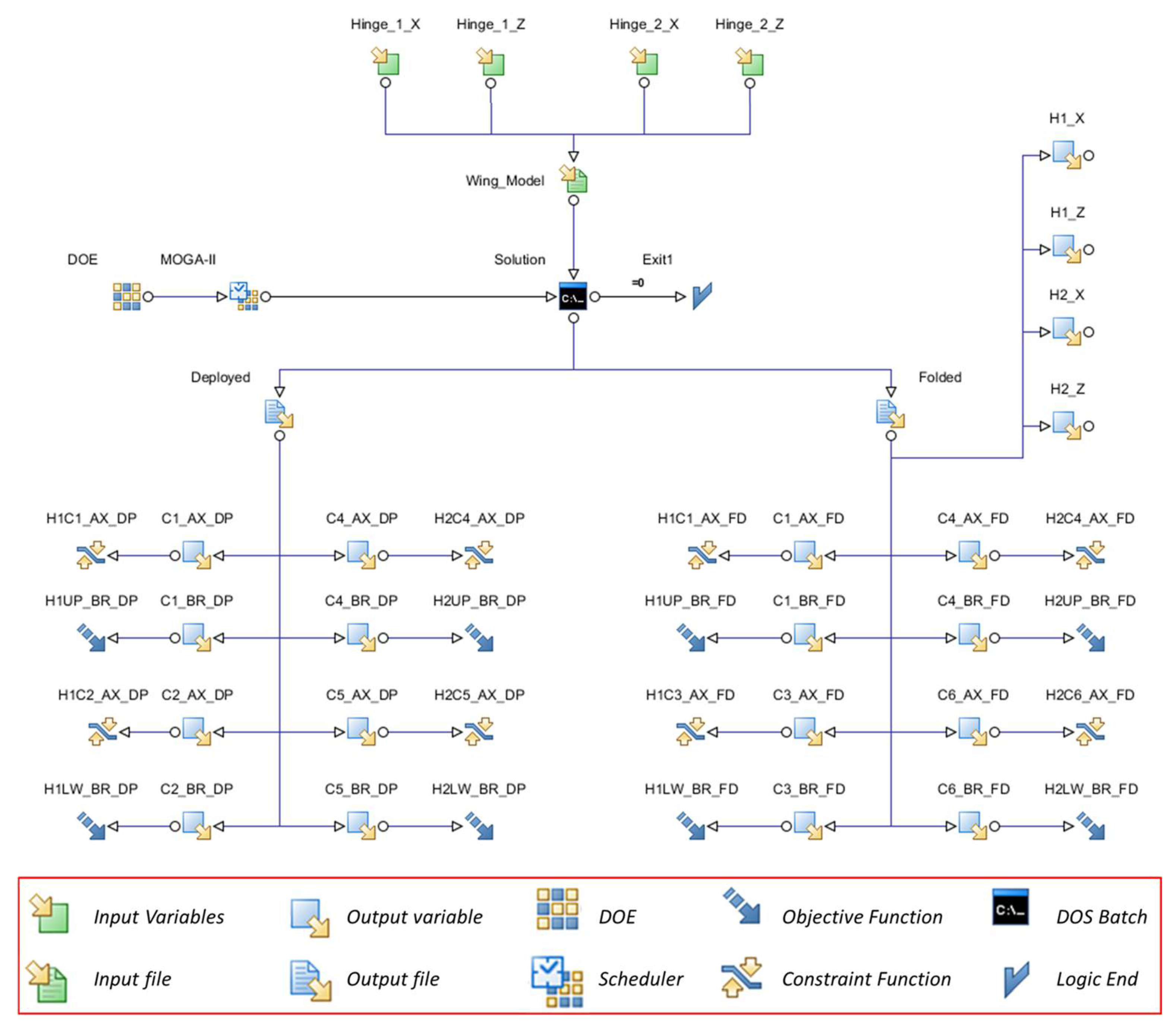
Figure 11 shows the defined workflow. The latter is composed of “nodes” connected to each other to define the logic data path. The input variable nodes are used to define the design variables, their allowable ranges and increments (in this case the variables are treat as discrete variables): the input file node is the APDL macro and it is used to translate the design variables in a format that ANSYS can manage, and, thus, it is the link between ModeFrontier and ANSYS; the DOS node is a simple shell dos that is used to call on demand ANSYS to execute the numerical simulation; the DOE (design of experiment) node is used to define the starting generation and connected to this node there is a Scheduler node that is the optimization algorithm to be used; the output file nodes have the same function of the input file nodes, but, in this case, the link is from ANSYS to ModeFrontier; the output variable nodes represent all data from the solver that are available for the optimization process (but can be also used simply as checking data); the constraint nodes are used to define the constraint functions and can be applied both in output and input variable; finally, the objective function nodes are used to define whether the process has to minimize or maximize well-defined output variables. The design variables consist of the coordinates of the centers of the holes C1, C2, C4, and C5, which are specifically defined in Table 3. The coordinates of points C3 and C6, relative to the folded configuration, are defined by the previous points and by the folding angle. The variables H1-X and H2-X are defined in a dimensionless way, in order to avoid unfeasible configurations, they are then converted into physical dimensions by the calculation routine. They can range from 0 to 1 with a step increment equal to 0.025. The variables H1-Z and H2-Z can range from 10 mm up to 50 mm with a step increment equal to 2.5 mm.
The developed APDL macro is the core of the optimization procedure as it can manage the design variable and translate them into an FE model ready to be solved by ANSYS, and, at the end of each design evaluation, it uses ANSYS to extract the output data that are then used in ModeFrontier as constraint and objective functions.
The initial sampling, named generation 0, was done with a SOBOL algorithm (it is based on a pseudo-random SOBOL sequence and enables the uniform distribution having of the experiments in the design space), and all generations were composed by 30 elements each, so-called individuals. The adopted optimization algorithm is MOGAII, which is a genetic multi-objective algorithm that supports geographical selection and directional cross-over, implements Elitism for multi-objective search, defines constraints by objective function penalization, and allows generational or steady state evolution. The evolution process is defined by 10 generations and the following main parameters are reported:
- (1)
- Probability of Directional Cross-Over = 0.5
- (2)
- Probability of Selection = 0.05
- (3)
- Probability of Mutation = 0.2
- (4)
- DNA String Mutation Ratio = 0.05
- (5)
- Elitism = Enabled
- (6)
- Treat Constraints = Penalizing Objectives
In the adopted workflow there are no constraints on the input variables. Such constraints, related to the congruence of the numerical model, are already implicitly implemented within the APDL-macro that generated the parametric model.
The output variables are the bearing and axial forces (in a local reference system) for each pin (hole’s center). In particular, since the bearing loads are the most critical values for such a problem, the last ones have been defined as objective functions while the axial loads have been set as constraint functions. As reported in the optimization workflow, the objective functions are eight and four for the deployed configuration and four for the folded configuration. Table 2 reports the limit value set for the constrain functions in terms of axial load on bolts (reaction load on the reference point of the MPC element). Further, Figure 12 reports the scheme adopted for identifying the output variables.
The optimization process evaluated 300 design sets and only a very reduced part (7.3%) of them were determined as unfeasible. A design is considered unfeasible if the constraints reported in Table 3 are violated.
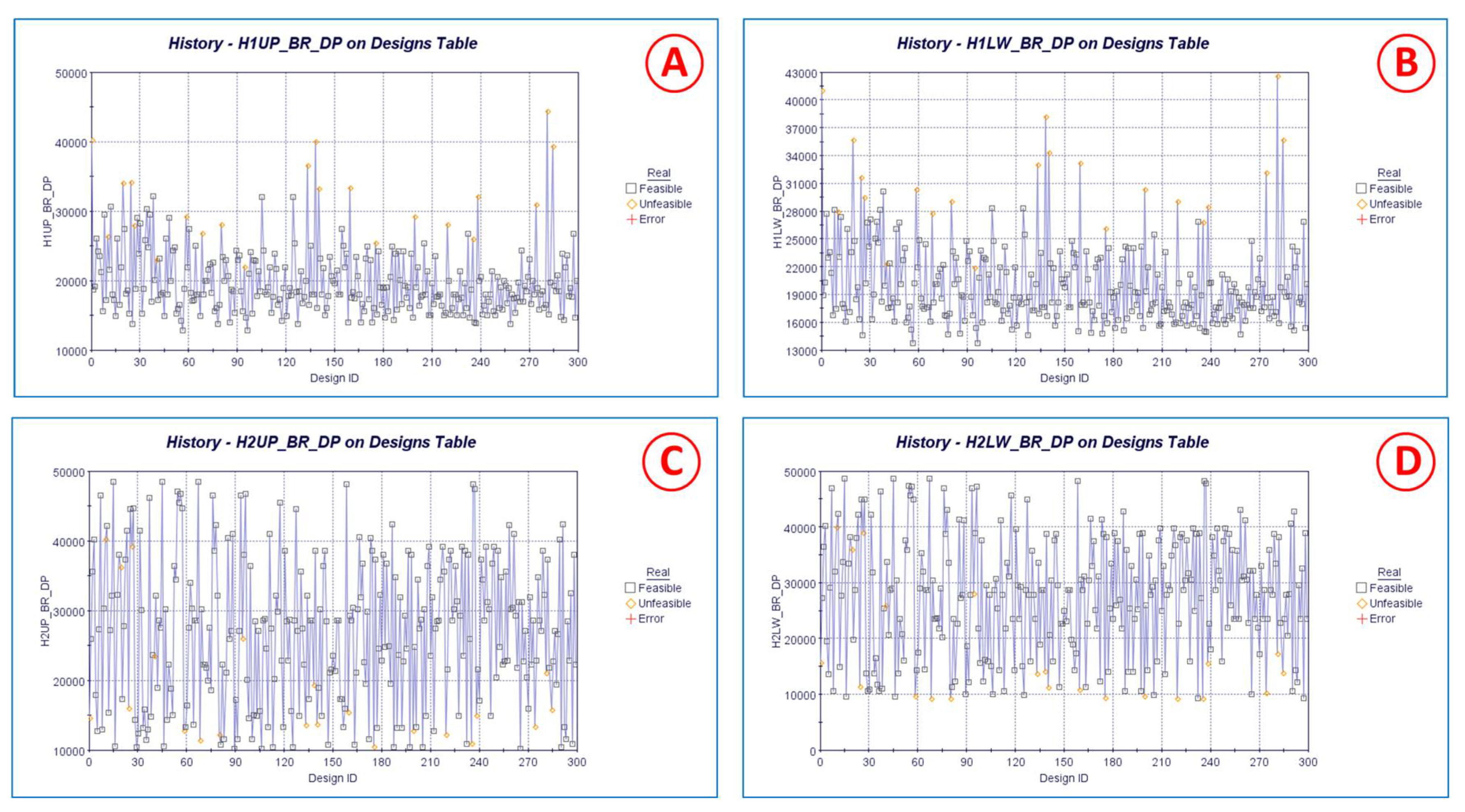
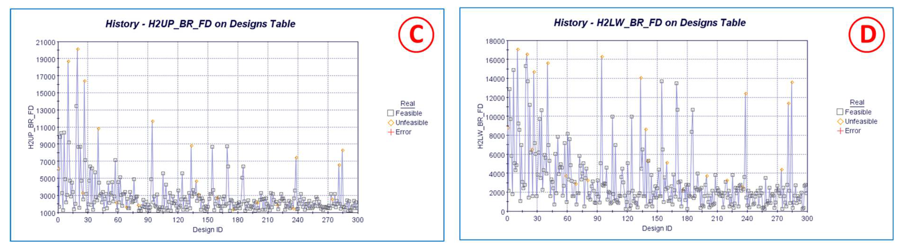
Figure 13 reports the time history of the objective functions H1UP_BR_DP, H1LW_BR_DP, H2UP_BR_DP, and H2LW_BR_DP, which are the bearing loads in the deployed configuration at the four constrained points. The results marked with a gray square are feasible, while those marked with an orange rhombus are unfeasible.
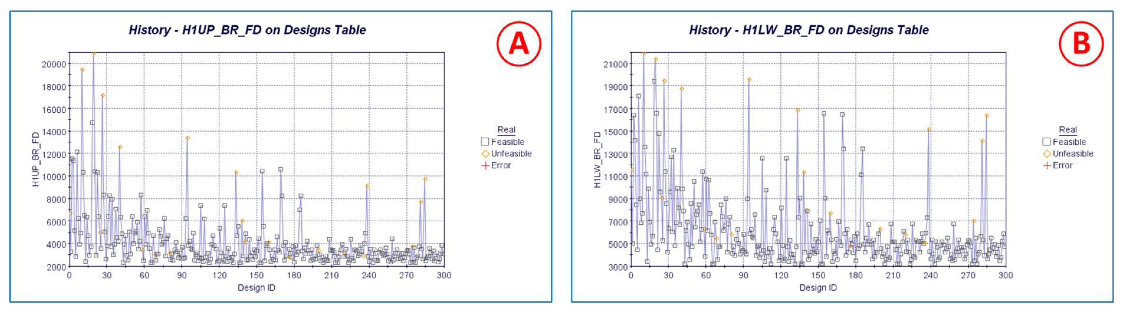
Figure 14 reports the time history of the objective functions H1UP_BR_FD, H1LW_BR_FD, H2UP_BR_FD, and H2LW_BR_FD, which are the bearing loads in the folded configuration at the four constrained points.
The previous figures show that it is only possible to see a clear trend in the folded configuration and, thus, the algorithm is able to provide design sets that are able to minimize the reaction forces for all hinges simultaneously. Conversely, in the deployed configuration, a sample is able to minimize only one or two objective functions and thus the best one has to be defined with a compromise.
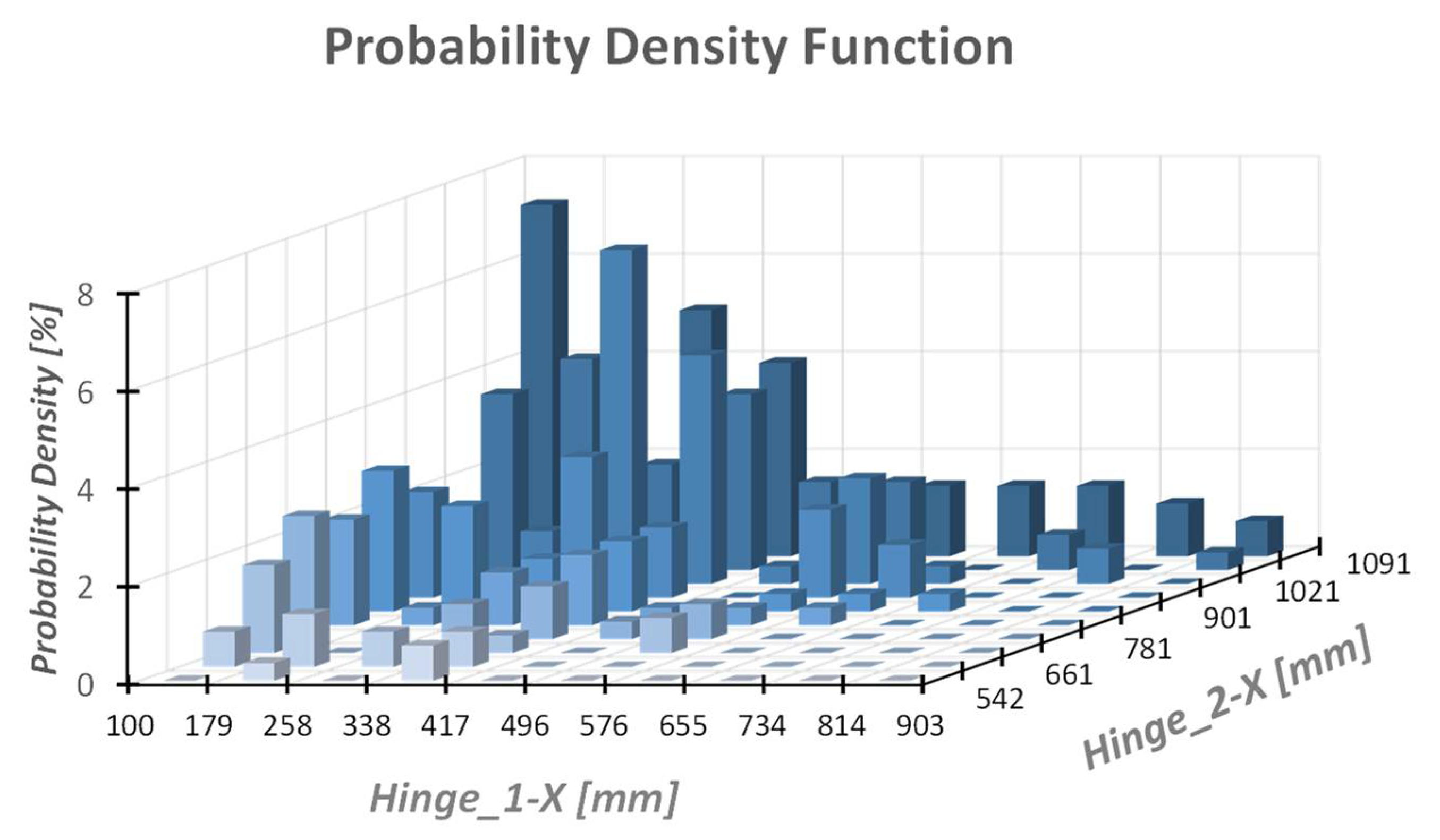
The probability density function, related only to feasible designs, for the two design variables (H1-X and H2-X) is shown in Figure 15. In an evolutive optimization process, the probability of selecting a particular sample depends on the fitness function. The latter is better for samples that satisfy the objective functions and the constraint functions with a bigger margin. Therefore, the better an individual is, the greater the likelihood that it will be re-selected and, therefore, that such a sample will survive into the next generations. Of course, if a sample appears many times during the evolution process, it one of the best samples.
Therefore, by relating the number of samples (w.r.t to total number) to a specific range, it is possible to quickly and easily understand which regions should be chosen for the hinges.
The graphs show that the most feasible values of the H1-X variable are concentrated in the range of 100–450 mm. For the variable H2-X, there is a thickening in the region 800–1080 mm. The results indicate that increasing the distance between the hinges is a valid option to reduce the bearing forces in the four points both for deployed and folded configurations. The H1-Z and H2-Z variables are quite obvious and the best value, for both of them, results in the smallest feasible value, that is 10 mm.
Simultaneous representation of all eight objective functions is not possible, therefore the last one has been divided into two groups. Each group reports the objective functions of its wing configuration.
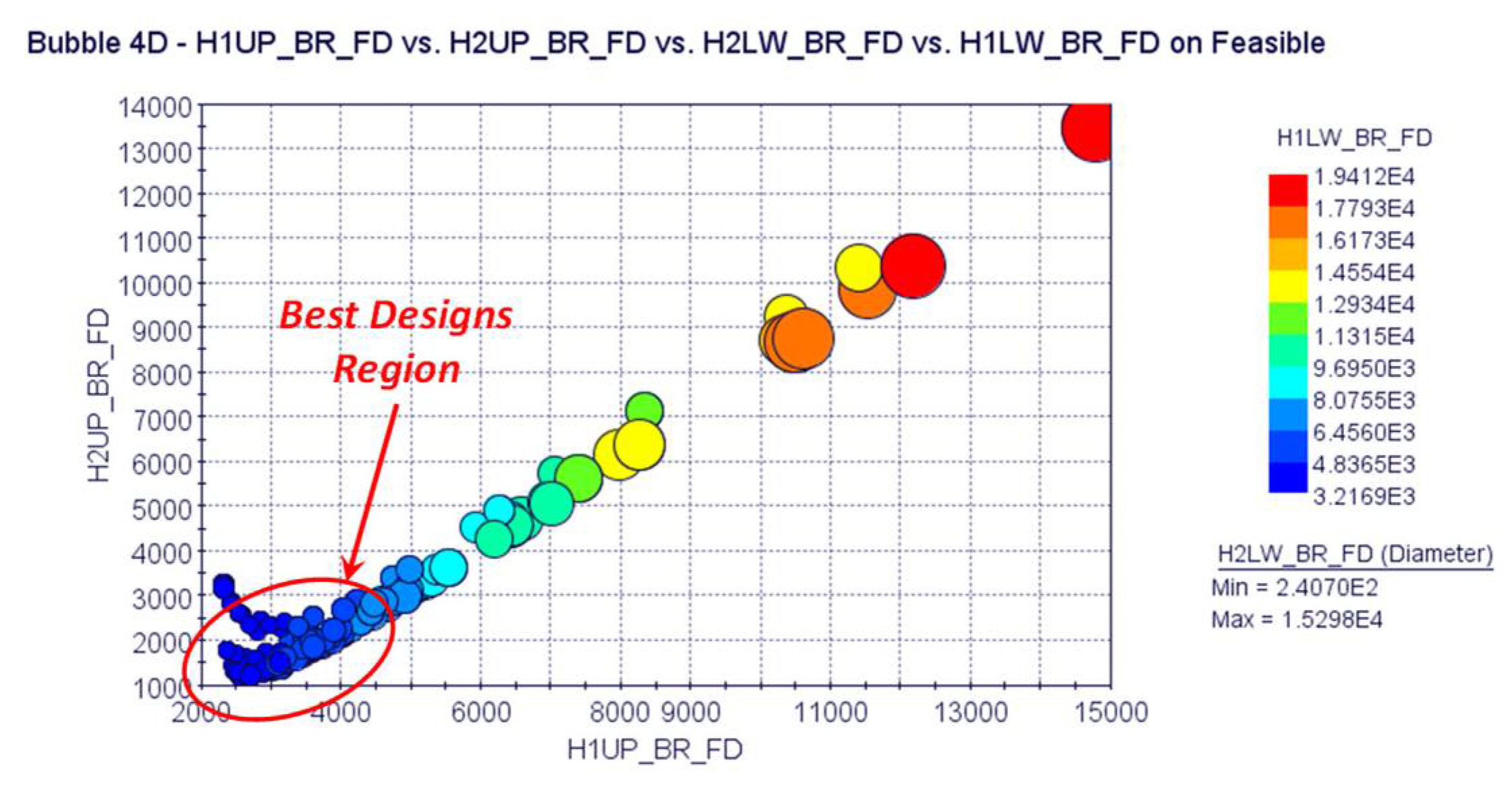
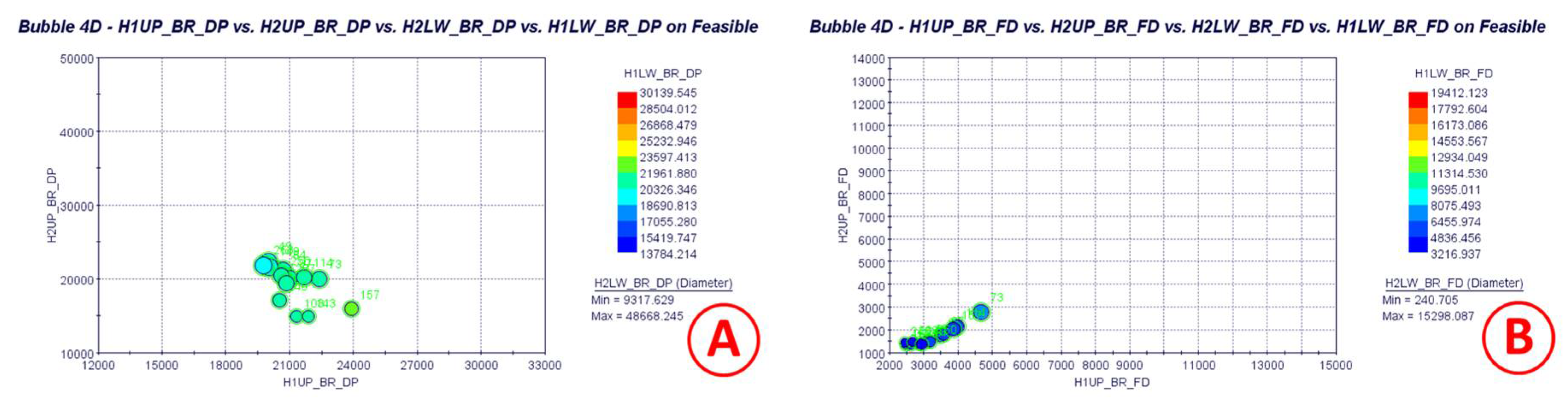
The 4D bubble graph of Figure 16 shows the objective functions relating to the deployed wing (only feasible designs). The horizontal and vertical axes report the bearing loads of the upper pin for forward and afterward hinge respectively, the bubble color refers to the bearing load of the lower pin of the forward hinge and, finally, the bubble size is related to the bearing load of the lower pin of the afterward hinge. The figure also highlights the region (which is part of the Pareto front) where individuals, even if they do not minimize a specific objective function, are a good compromise in the minimization of the four bearing loads (all bearing loads are about 20 kN).
The bubble-graph 4D of Figure 17 shows the objective functions relating to the folded wing (only feasible designs). In this case, it is evident that the selection of the optimal individuals is simplified since many individuals are able to simultaneously minimize the four objective functions.
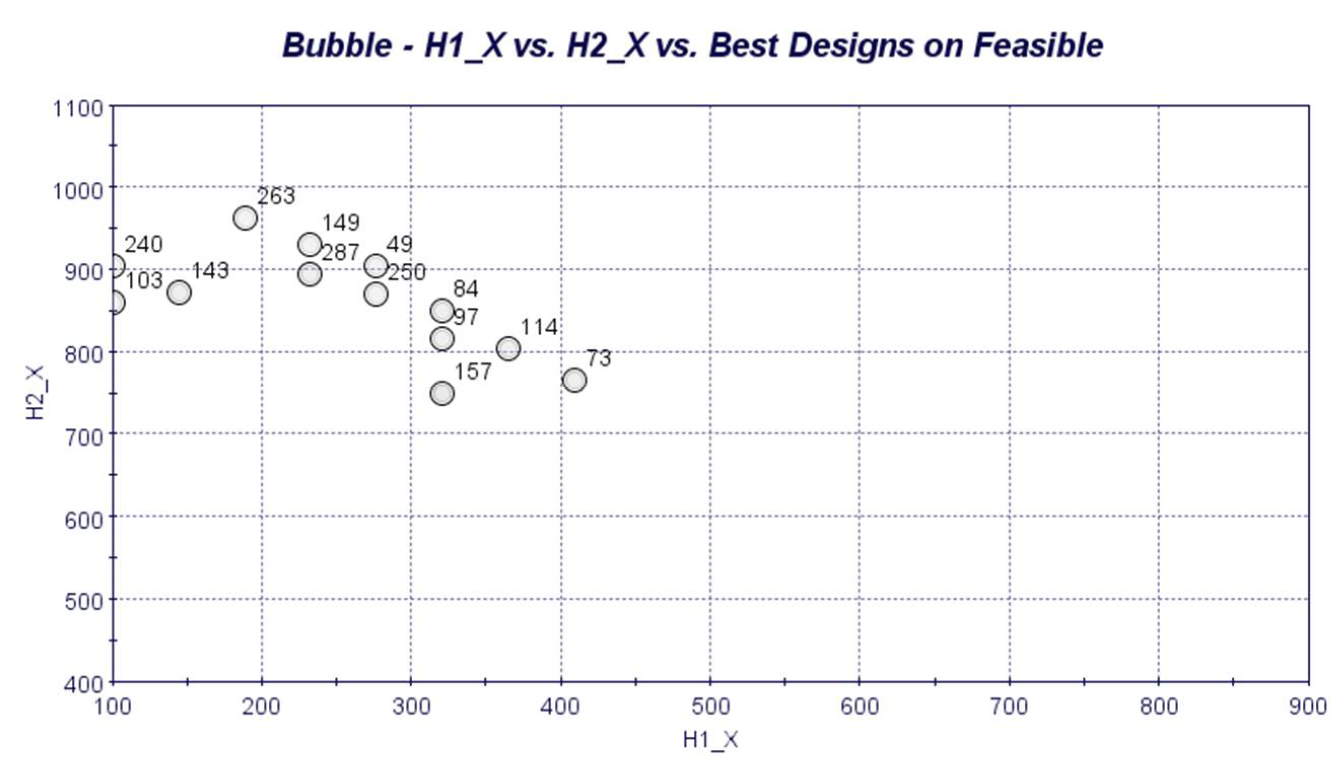
Many of the individuals belonging to the region highlighted in Figure 16 (deployed configuration) are also highlighted in Figure 17 (folded configuration). Figure 18 shows only the elements present in both regions. About 13 designs can be considered as the best ones for both configurations.
Figure 19 shows the individuals present in both regions defined above, and, in particular, it is possible to relate any selected individual to the design variables. This graph highlights again that the objective functions are minimized as the relative distance between the two hinges increases. All selected designs provide bearing loads close to each other and therefore any of them is not clearly better than another one. Therefore, the final choice could be completed considering other functional requirements, such as the real possibility of installing the hinges in the selected regions.
The obtained results enable a preliminary estimation of the diameters of the bolts/pins and the plate thickness. For the subsequent evaluations, only the bearing components were taken into account as they are strictly connected to the sizing of both the locking pins (in the unfolded and folded configuration) and the rotation axes. Because of the mission of the investigated vehicle and, therefore, due to the operative temperature, the pins, the lag, and the hinge axes are made of titanium alloy Ti6Al4V. Considering an operative temperature equal to 160 °C, the tensile ultimate strength is equal to about 720 MPa, the shear ultimate stress is about 398 MPa and the bearing stress is 1071 MPa.
To estimate the diameters and the thickness of the connection components, only the maximum loads from the best design sets, for each configuration (wing unfolded and folded), have been considered. Table 3 shows the minimum diameters of the locking pins and hinge rods, considering a safety factor equal to 1.5 and a number of cutting planes equal to 2. Even if the ECCS handbook requires a smaller safety factor, in this context, a more conservative safety factor was adopted since the vehicle is still in phase 0/A.
Considering the diameters of the previous table, it is possible to estimate the thickness of the plate in order to not incur breakages due to exceeding the allowable bearing (Table 4) values. In this case, the yield value was considered as the reference value.
Finally, the net section failure for the lug used to retain the locking pins is reported (Table 5). The general rules prescribe that the widths are not less than two times the diameter of the hole, therefore, having previously determined the diameter of the hole it is possible to estimate the thickness of the lug.
5. Conclusions
The present work illustrates a structural optimization procedure for the definition of a deployable wing connection system of a sub-orbital unmanned re-entry vehicle (USV3), class 2500 kg, equipped with a deployable wing housed within the fairing of the European VEGA-C launcher. The obtained results provide useful data for the preliminary design of the deployment system consisting of two hinges, which allow the wing deployment after it is placed in orbit, and, thus, allow a descent, a hypersonic flight, and a landing phase with greater control capabilities.
The optimization process uses two pieces of commercial software (ModeFrontier and ANSYS) and, in particular, it exploits a fully parametric model generated by means of an APDL macro and a multi-objective genetic algorithm. The optimization process focuses on minimizing the bearing forces that are generated by the design loads, defined both by the launch phase (inertial loads) and by the hypersonic flight phase (aerodynamic loads).
The results show how it is possible to significantly reduce the loads on the hinges by shifting these in strategic convenient positions. In particular, a set of optimum designs has been defined (hinge location) that is able to minimize the loads, both in the deployed and folded configuration. The hinges, obviously, have to be positioned within the root rib domain, and the optimization process has shown that the optimal position of the forward hinge (point C1) is between 100 and 400 mm w.r.t the leading edge of the root profile in the longitudinal direction. The afterward hinge (point C4) should be positioned between 750 and 962 mm (remember that the maximum dimension of the root rib is 1180 mm). Regarding the transversal position, for both hinges (point C2 and C5) the locking pins have to be positioned as low as possible, i.e., at 10 mm. The remaining two points C3 and C6 are automatically determined considering that the maximum wing rotation that is 55°.
The optimization process provides several configurations suitable to be used as the best design. Indeed, they are able to minimize both the diameter of the pins/bolts and the thickness of the surrounding and locking plates. This guarantees the fulfillment of a fundamental requirement, i.e., structural mass reduction. The final choice could be completed considering other functional requirements/constraints that will be discussed and introduced in a subsequent design phase, which will also include the detailed design of the deployment system.
Author Contributions
Conceptualization, F.D.C., R.S., R.F. and D.T.; Data curation, R.S. and R.F.; Formal analysis, F.D.C.; Investigation, F.D.C.; Methodology, F.D.C. and R.F.; Project administration, R.F.; Supervision, D.T.; Visualization, R.S.; Writing—original draft, F.D.C., R.S. and D.T.; Writing—review & editing, R.F. and D.T. All authors have read and agreed to the published version of the manuscript.
Funding
This research received no external funding.
Data Availability Statement
Not applicable.
Conflicts of Interest
The authors declare no conflict of interest.
References
- Tumino, G.; Mancuso, S.; Gallego, J.-M.; Dussy, S.; Preaud, J.-P.; Di Vita, G.; Brunner, P. The IXV experience, from the mission conception to the flight results. Acta Astronautica 2016, 124, 2–17. [Google Scholar] [CrossRef]
- Bernard, R.; Pichon, T.; Valverde, J. From IXV to Space Rider, CMC Thermal Protection System Evolutions. In Proceedings of the International Conference on Flight Vehicles, Aerothermodynamics and Re-entry Missions & Engineering (FAR2019), Monopoli, Italy, 30 September–3 October 2019. [Google Scholar]
- Heidenreich, B. Carbon Fibre Reinforced SiC Materials Based on Melt Infiltration. In Proceedings of the 6th International Conference on High Temperature Ceramic Matrix Composites (HTCMC 6), New Delhi, India, 4–7 September 2007. [Google Scholar]
- Handrick, K.E. Ceramic Matrix Composites (CMC) for demanding Aerospace and Terrestrial Applications. In Proceedings of the XXI Congress AIV, Catania, Italy, 15–17 May 2013. [Google Scholar]
- Lange, H.; Steinacher, A.; Handrick, K.; Weiland, S.; Glass, D.; Wurster, K.; Robinson, J.; Greene, F. Advanced CMC TPS design concepts for re-usable re-entry vehicles. In Proceedings of the 5th European Workshop on Thermal Protection Systems and Hot Structures, Noordwijk, The Netherlands, 17–19 May 2006. [Google Scholar]
- Glass, D. Ceramic Matrix Composite (CMC) Thermal Protection Systems (TPS) and Hot Structures for Hypersonic Vehicles. In Proceedings of the 5th AIAA Space Planes and Hypersonic Systems and Technologies Conference, Munich, Germany, 30 November–3 December 1993. [Google Scholar]
- Scigliano, R.; Belardo, M.; De Stefano Fumo, M.; Esposito, A. Thermo-Mechanical Numerical Model Set-up and Validation Approach for a CMC Control Surface for Re-entry Vehicles. In Proceedings of the SPACE Conference and Exposition, Long Beach, CA, USA, 5 May 2016. [Google Scholar] [CrossRef]
- De Stefano Fumo, M.; Belardo, M.; Scigliano, R.; Marino, G.; Cantoni, S.; Cavalli, L.; Valle, M. An Italian Technology for LSI-based CMC Control Surfaces for Re-entry Vehicles. In Proceedings of the 68th International Astronautical Congress (IAC2017), Adelaide, Australia, 25–29 September 2017. [Google Scholar]
- Scigliano, R.; Belardo, M.; De Stefano Fumo, M.; Celentano, S. Numerical Model Set-Up and Virtual Testing of a CMC Flap for Re-Entry Vehicle. In Proceedings of the ASME 2017 International Mechanical Engineering Congress & Exposition IMECE 2017, Tampa, FL, USA, 3–9 November 2017. [Google Scholar]
- De Stefano Fumo, M.; Guidotti, G.; Paletta, N.; Richiello, C.; Vecchione, L. USV3 an autonomous Space Vehicle with Re-Entry and Landing Capability. In Proceedings of the SAE 2013 AeroTech Congress & Exhibition, New York, NY, USA, 24 September 2013. [Google Scholar] [CrossRef]
- Petrosino, F.; Pezzella, G.; De Stefano Fumo, M.; Catalano, P.; Cinquegrana, D.; Mingione, G. Aerodynamic performances of USV3 CIRA re-entry vehicle. In Proceedings of the 63rd International Astronautical Congress, AC-12-D2.3.7, Naples, Italy, 1–5 October 2012. [Google Scholar]
- Schettino, A.; Filippone, E.; Mingione, G.; Pezzella, G.; Solazzo, M.; Salvatore, V.; de Matteis, P.; Bertuccio, E.; Massobrio, F. Mission Trade-off Analysis of the Italian USV Re-entry Flying Test Bed. In Proceedings of the 14th AIAA/AHI Space Planes and Hypersonic Systems and Technologies Conference, Canberra, Australia, 6 November–9 November 2006. AIAA 2006-8017. [Google Scholar]
- Fauci, R.; Belardo, M.; Marini, M.; Guidotti, G.; Rufolo, G. The USV 3 DWS Project-Unmanned Re-entry Vehicle Deployable Wing System. In Proceedings of the AIDAA XXIV International Congress, Palermo, Italy, 18–19 September 2017. [Google Scholar]
- Roland LAGIER. Vega C User’s Manual by Arianespace Group. Available online: https://www.arianespace.com/wp-content/uploads/2018/07/Vega-C-user-manual-Issue-0-Revision-0_20180705.pdf (accessed on 9 April 2021).
- ANSYS Inc. Structural Analysis Guide. Available online: http://download.hangtuah.ac.id/ansys/ansys-2020/Docs/Ansys.Products.PDF.Docs.2020R1/v201/ANSYS_Mechanical_APDL_Structural_Analysis_Guide.pdf (accessed on 9 April 2021).
- ModeFrontier Esteco. User manual. Available online: https://www.esteco.com/modefrontier (accessed on 9 April 2021).
- Di Caprio, F.; Sellitto, A.; Saputo, S.; Guida, M.; Riccio, A. A Sensitivity Analysis of the Damage Behavior of a Leading-Edge Subject to Bird Strike. Appl. Sci. 2020, 10, 8187. [Google Scholar] [CrossRef]
- Di Caprio, F.; Acanfora, V.; Franchitti, S.; Sellitto, A.; Riccio, A. Hybrid Metal/Composite lattice structures: Design for Additive Manufacturing. Aerospace 2019, 6, 71. [Google Scholar] [CrossRef] [Green Version]
- Di Caprio, F.; Riccio, A.; Scaramuzzino, F. A novel approach for the damage tolerance determination of delaminated stiffened composite panels. In Proceedings of the 13th International Conference on Civil, Structural and Environmental Engineering Computing, Chania, Greece, 6–9 September 2011. [Google Scholar]
- Carriglio, M.; Clarich, A.; Russo, R.; Nobile, E.; Ranut, P. ModeFRONTIER for Virtual Design and Optimization of Compact Heat Exchangers; SAE Technical Paper 2014-01-2406; SAE International: Warrendale, PA, USA, 2014. [Google Scholar] [CrossRef]
Figure 1.
(A) USV3 “WB-B3” with deployed wings; (B) USV3 “WB-B3” in stored configuration inside the VEGA-C fairing.
Figure 1.
(A) USV3 “WB-B3” with deployed wings; (B) USV3 “WB-B3” in stored configuration inside the VEGA-C fairing.

Figure 2.
USV3 “WB-B3” DWS: reduced gap and avoided interferences requirements.

Figure 3.
Hook pins with linear actuator CAD 3D schematic view.

Figure 4.
USV3′s wing in starting configuration.

Figure 5.
Hinge and stopper axes with a detail of the holes in which the reaction loads are evaluated. C1 and C4 are placed along the hinge axis and they are considered both in deployed and folded configuration; C2 and C5 accommodate the stopper pins in the deployed configuration; C3 and C6 accommodate the stopper pins in the folded configuration.

Figure 6.
Defined design variables.

Figure 7.
Global dimension and loading points.

Figure 8.
Simplified numerical model with axis location. (A) Deployed Configuration; (B) Folded Configuration.
Figure 8.
Simplified numerical model with axis location. (A) Deployed Configuration; (B) Folded Configuration.

Figure 9.
FE model. (A) Global Model; (B) Hinge detail.

Figure 10.
Boundary conditions with global and local reference systems.

Figure 11.
Optimization workflow.

Figure 12.
Output variables definition.

Figure 13.
Objective function time history in the deployed configuration. (A) forward hinge in upper location; (B) forward hinge in lower location; (C) afterward hinge in upper location; (D) afterward hinge at a lower location.
Figure 13.
Objective function time history in the deployed configuration. (A) forward hinge in upper location; (B) forward hinge in lower location; (C) afterward hinge in upper location; (D) afterward hinge at a lower location.

Figure 14.
Objective function time history in the folded configuration. (A) forward hinge in upper location; (B) forward hinge in lower location; (C) afterward hinge in upper location; (D) afterward hinge at a lower location.
Figure 14.
Objective function time history in the folded configuration. (A) forward hinge in upper location; (B) forward hinge in lower location; (C) afterward hinge in upper location; (D) afterward hinge at a lower location.


Figure 15.
Probability Density Function of feasible designs.

Figure 16.
Pareto front of the deployed configuration.

Figure 17.
Pareto front of the folded configuration.

Figure 18.
Best designs for both configurations. (A) deployed Conf.; (B) folded Conf.

Figure 19.
Best designs set. X-station of forward and afterward hinges.


Table 1.
Main preliminary requirements.
| Req. Id. | Requirement Description | |
|---|---|---|
| F1 | Maximum deployable wing rotation angle: 55° | |
| F2 | Deployable wing Mass: 92.15 kg (preliminary) | |
| F3 | During the Re-entry and Descent Phase the DWS shall withstand the following Static Loads: F = 13.6 kN (at the PtL; Z direction) | |
| F4 | During the Launch/Ascent phase the system shall withstand the following Quasi Static Loads (QSL) * |  |
* as for VEGA-C launcher user manual [14].
Table 2.
Constraint functions.
| Optimization Analysis Constraint Functions | |||||
|---|---|---|---|---|---|
| Variable | Hinge Location | Wing Configuration | Constrained Point | Force Type | Less than |
| H1C1-AX_DP | Forward | Deployed | C1 | Axial | 7500 |
| H1C2-AX_DP | Forward | Deployed | C2 | Axial | 7500 |
| H2C4-AX_DP | Afterward | Deployed | C4 | Axial | 10,000 |
| H2C5-AX_DP | Afterward | Deployed | C5 | Axial | 10,000 |
| H1C1-AX_FD | Forward | Folded | C1 | Axial | 7500 |
| H1C3-AX_FD | Forward | Folded | C3 | Axial | 2000 |
| H2C4-AX_FD | Afterward | Folded | C4 | Axial | 10,000 |
| H2C6-AX_FD | Afterward | Folded | C6 | Axial | 2000 |
Table 3.
Preliminary evaluation of the diameter of locking pins and bolts.
| Wing Configuration | Max Force [N] | Yield Stress [MPa] | SF | Shear Plane | Min Bolt Area [mm2] | Min Bolt Diameter [mm] |
|---|---|---|---|---|---|---|
| Deployed | 23,878.6 | 398.3 | 1.5 | 2 | 44.96 | 7.57 |
| Folded | 7449.1 | 398.3 | 1.5 | 2 | 14.03 | 4.23 |
Table 4.
Preliminary evaluation of the thickness of connecting plates.
| Wing Configuration | Max Force [N] | Yield Bearing [MPa] | SF | Min Bolt Diameter [mm] | Plate Thickness [mm] |
|---|---|---|---|---|---|
| Deployed | 23,878.6 | 1071.8 | 1.5 | 7.57 | 4.42 |
| Folded | 7449.1 | 1071.8 | 1.5 | 4.23 | 2.47 |
Table 5.
Preliminary evaluation of the retained lags thickness.
| Wing Configuration | Max Force [N] | Yield Bearing [MPa] | SF | Min Bolt Diameter [mm] | Plate Thickness [mm] |
|---|---|---|---|---|---|
| Deployed | 23,878.6 | 530.6 | 1.5 | 7.57 | 8.92 |
| Folded | 7449.1 | 530.6 | 1.5 | 4.23 | 4.98 |
Publisher’s Note: MDPI stays neutral with regard to jurisdictional claims in published maps and institutional affiliations. |
© 2021 by the authors. Licensee MDPI, Basel, Switzerland. This article is an open access article distributed under the terms and conditions of the Creative Commons Attribution (CC BY) license (https://creativecommons.org/licenses/by/4.0/).
Share and Cite
MDPI and ACS Style
Di Caprio, F.; Scigliano, R.; Fauci, R.; Tescione, D. Design Optimization of Interfacing Attachments for the Deployable Wing of an Unmanned Re-Entry Vehicle. Algorithms 2021, 14, 141. https://0-doi-org.brum.beds.ac.uk/10.3390/a14050141
AMA Style
Di Caprio F, Scigliano R, Fauci R, Tescione D. Design Optimization of Interfacing Attachments for the Deployable Wing of an Unmanned Re-Entry Vehicle. Algorithms. 2021; 14(5):141. https://0-doi-org.brum.beds.ac.uk/10.3390/a14050141
Chicago/Turabian StyleDi Caprio, Francesco, Roberto Scigliano, Roberto Fauci, and Domenico Tescione. 2021. "Design Optimization of Interfacing Attachments for the Deployable Wing of an Unmanned Re-Entry Vehicle" Algorithms 14, no. 5: 141. https://0-doi-org.brum.beds.ac.uk/10.3390/a14050141
Note that from the first issue of 2016, this journal uses article numbers instead of page numbers. See further details here.