Article

An Adaptive Neuro-Fuzzy Control of Pneumatic Mechanical Ventilator

1
Department of Biomedical Engineering and Measurement, Faculty of Mechanical Engineering, Technical University of Košice, 04200 Košice, Slovakia
2
Department of Mechatronics, Faculty of Mechanical Engineering, Technical University of Košice, 04200 Košice, Slovakia
3
Department of Production Systems and Robotics, Faculty of Mechanical Engineering, Technical University of Košice, 04200 Košice, Slovakia
4
KYBERNETES, s.r.o., Omská 14, 04001 Košice, Slovakia
*
Author to whom correspondence should be addressed.
Submission received: 5 February 2021 / Revised: 26 February 2021 / Accepted: 2 March 2021 / Published: 6 March 2021
(This article belongs to the Special Issue Pneumatic Actuators for Robotics and Automation)

Abstract

:
COVID-19 was first identified in December 2019 in Wuhan, China. It mainly affects the respiratory system and can lead to the death of the patient. The motivation for this study was the current pandemic situation and general deficiency of emergency mechanical ventilators. The paper presents the development of a mechanical ventilator and its control algorithm. The main feature of the developed mechanical ventilator is AmbuBag compressed by a pneumatic actuator. The control algorithm is based on an adaptive neuro-fuzzy inference system (ANFIS), which integrates both neural networks and fuzzy logic principles. Mechanical design and hardware design are presented in the paper. Subsequently, there is a description of the process of data collecting and training of the fuzzy controller. The paper also presents a simulation model for verification of the designed control approach. The experimental results provide the verification of the designed control system. The novelty of the paper is, on the one hand, an implementation of the ANFIS controller for AmbuBag pressure control, with a description of training process. On other hand, the paper presents a novel design of a mechanical ventilator, with a detailed description of the hardware and control system. The last contribution of the paper lies in the mathematical and experimental description of AmbuBag for ventilation purposes.

1. Introduction

COVID-19 (Coronavirus disease 2019), caused by severe acute respiratory syndrome coronavirus 2 (SARS-CoV-2), has become a global world pandemic with an exponential growth rate. The virus commonly manifests with few symptoms but can also lead to a rapidly progressive fatal pneumonia [1]. According to the World Health Organization (WHO) [2], up to now (January 2021), COVID-19 has reached 2.16% mortality from all infected subjects. COVID-19 is one of the most contagious viruses that mankind has experienced, spreading across most of China in only 14 days [3], and then worldwide within a couple of months [4]. The ventilation systems are frequently the main reason critically ill patients require transfer to the critical care units [5].
In general, the process of mechanical ventilation controls the flow, volume, and pressure of air and gases to a patient’s lung [6]. An artificial lung ventilation (ALV) represents the way of respiration. The respiration device provides flow of a gas through a respiration system. ALV is either used for short-term or long-term support for patients with serious damage of their respiration system. From the clinical point of view, ALV comes with potential risks and complications, which need to be known in order to get suitable clinical results [7].
A study from 2013 declared that it is estimated that ALV is required by roughly 1.5 million patients in the United States every year [8]. According to References [9,10], the mortality of patients undergoing ventilation during critical disease is 31–37%. The decision to use ALV is based on several factors and should be carefully evaluated. The rough factors are evaluation of parameters of oxygenation, ventilation, lung mechanics, and condition of the infected person. However, evaluation of past condition as well as supposed progress of patient’s condition are very significant. This concept seems to be more suitable rather than only evaluation of boundary values of concrete indicators. Each patient is unique, and their condition can be specific, and therefore, ALV should be optimized according to the patient’s lung mechanics [7].
Since the situation with COVID-19 has grown to a global scale, our research team from Cognitics Lab (Košice, Slovakia) has focused on the development of a robust, portable, and stable alternative solution, resulting in an emergency mechanical ventilator. The paper is organized as follows. First, previous solutions of AmbuBag-based mechanical ventilators are introduced. The next section deals with the design of the mechanical ventilator from the view of mechanics and hardware. We present necessary requirements for the mechanical ventilator. Subsequently, the control system based on an adaptive neuro-fuzzy inference system is designed. The processes of collecting of training data and the training process itself are shown. The developed fuzzy controller is verified by simulations and experiments with the mechanical ventilator. Finally, the results are discussed.

2. Related Works

As mentioned above, this work is focused on a simple and low-cost mechanical ventilator, which has potential to be produced quickly and in large quantities. The importance of this mechanical ventilator occurs in very critical pandemic situations, where the number of critical patients exceeds the number of available high-level ventilators in the hospitals.
This section describes related works with a focus on low-cost ventilators. In Reference [11], the authors developed a microcontroller-based mechanical ventilator with the AmbuBag mechanism. The AmbuBag is pressed by the arm based on the camshaft (CAM) principle. The system is able to work in several modes, such as child mode, pediatric mode, and adult mode. The experimental results show the time course of tidal volume. In Reference [12], the authors deal with a low-cost, open-source mechanical ventilator. The work was initiated by the worldwide shortage of mechanical ventilators for treating patients with COVID-19. The system uses AmbuBag, which is pressed by a Raspberry Pi-controlled mechanism. The ventilator uses a pressure sensor, which is able to measure maximum pressure up to 70 cmH2O. Another low-cost portable mechanical ventilator based on compressing of AmbuBag with a pivoting CAM arm is described in Reference [13]. The ventilator is controlled by Arduino. The prototype had user-controlled breath rate and tidal volume. It features assist control and an over-pressure alarm. The next work dealing with a simple ventilator is Reference [14]. The experimental results were consistent with clinical requirements from the view of achieved volume and pressure. The authors discussed challenges for the future work of their ventilator such as reliability of the mechanisms and software, mass production with appropriate standards, and regulatory approval or exemption. In Reference [15], the authors developed a simple and easy-to-build portable automated AmbuBag compression system which can serve as an emergency ventilator. The system is controlled by Arduino. The device provides a controlled breathing mode with tidal volumes from 100 to 800 mL, breathing rates from 5 to 40 breaths/minute, and inspiratory-to-expiratory ratio from 1:1 to 1:4. The experimental results showed repeatability and accuracy exceeding human capabilities in AmbuBag-based manual ventilation. In Reference [16], a ventilator was designed, where AmbuBag is compressed by two paddles actuated by an electric motor. In Reference [17], a mechanical ventilator is presented which was authorized by the Spanish Agency for Medicines and Health Products (AEMPS), under the Ministry of Health, Consumption, and Social Welfare. The ventilator is electronically controlled for pressure-controlled ventilation.
Based on the above-mentioned works as well as on other AmbuBag-based ventilators, it can be declared that most of them use electromechanical actuators to compress AmbuBag. Our solution is based on a pneumatic system which compresses AmbuBag, since the supplies of compressed air are commonly part of the hospital rooms. The advantage of the pneumatic actuator is also seen in its linear speed. In the case of an absence of compressed air supply, the system can use a mobile air compressor. By analyzing previous works, it can be seen that most of them do not offer insight into their control algorithm. It is also important to investigate the characteristics of AmbuBag, as according to our best knowledge, this has not yet been mathematically and experimentally analyzed in previous works. Due to the pandemic situations related to COVID-19, and by summarizing the mentioned facts, on the one hand, the motivation to develop our own mechanical ventilator arose, which would be simple, robust, portable, quickly reproducible, IoT-based, and usable in hospitals, field hospitals, and households. On the other hand, our motivation is to provide insight into the control algorithm for other open-source medical projects, which could help in the current pandemic situation.
The novelty and the main contributions of the paper are the development of an AmbuBag-based mechanical ventilator with a novel concept, mathematical description, and experimental analysis of AmbuBag, and the development of an adaptive neuro-fuzzy control system to control the pressure.

3. Design of the Mechanical Ventilator

This section provides the requirements of the mechanical ventilator. Subsequently, the mechanical design of the ventilator, which is based on proportional pneumatic control, is introduced. The section also introduces a detailed hardware design of low-level control and information flow of the control system as well.

3.1. Requirements of the Mechanical Ventilator

From the moment COVID-19 officially appeared in Central Europe (February 2020), our research team from Cognitics Lab started work on our own low-cost mechanical ventilator. The requirements for the ventilator BreaThU can be divided into two groups: the first group concerns the ventilation and control, and the second group concerns the mechanical design.
According to a specification of minimally clinically acceptable ventilators to be used in UK hospitals during the current COVID-19 pandemic, caused by SARS-CoV-2 virus [18], the requirements of our mechanical ventilator from the view of ventilation and control are:
  • Possibility of pressure control ventilation (PCV).
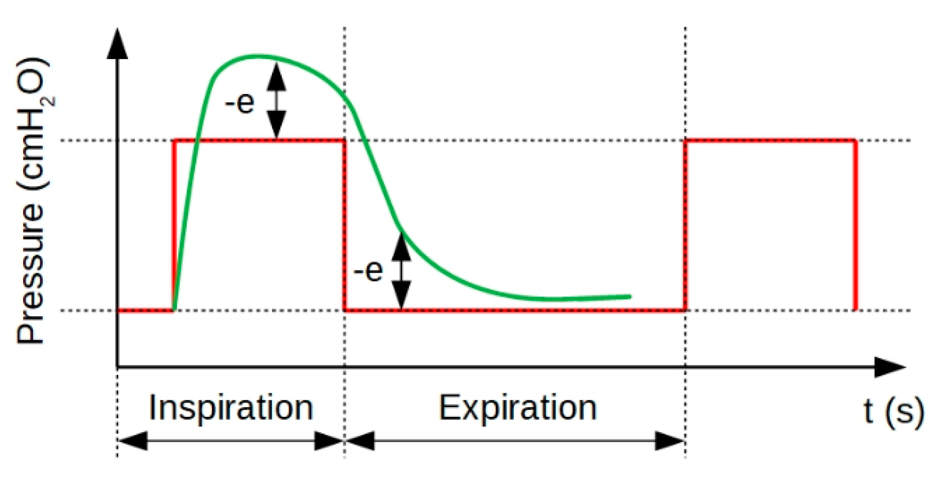
  • Peak pressure should be no more than 2 cmH2O greater than plateau pressure.
  • PEEP (Positive end-expiratory pressure) must be maintained during expiration.
  • For the ratio of inspiration phase/expiration phase, the ventilator must provide a ratio in the range 1:1–1:3.
  • The ventilator must provide a range of 10–30 breaths per minute.
  • The volume of gas flowing into the lungs during one inspiratory cycle must be at least 400 mL.
The requirements of the mechanical ventilator from the view of mechanical design are:
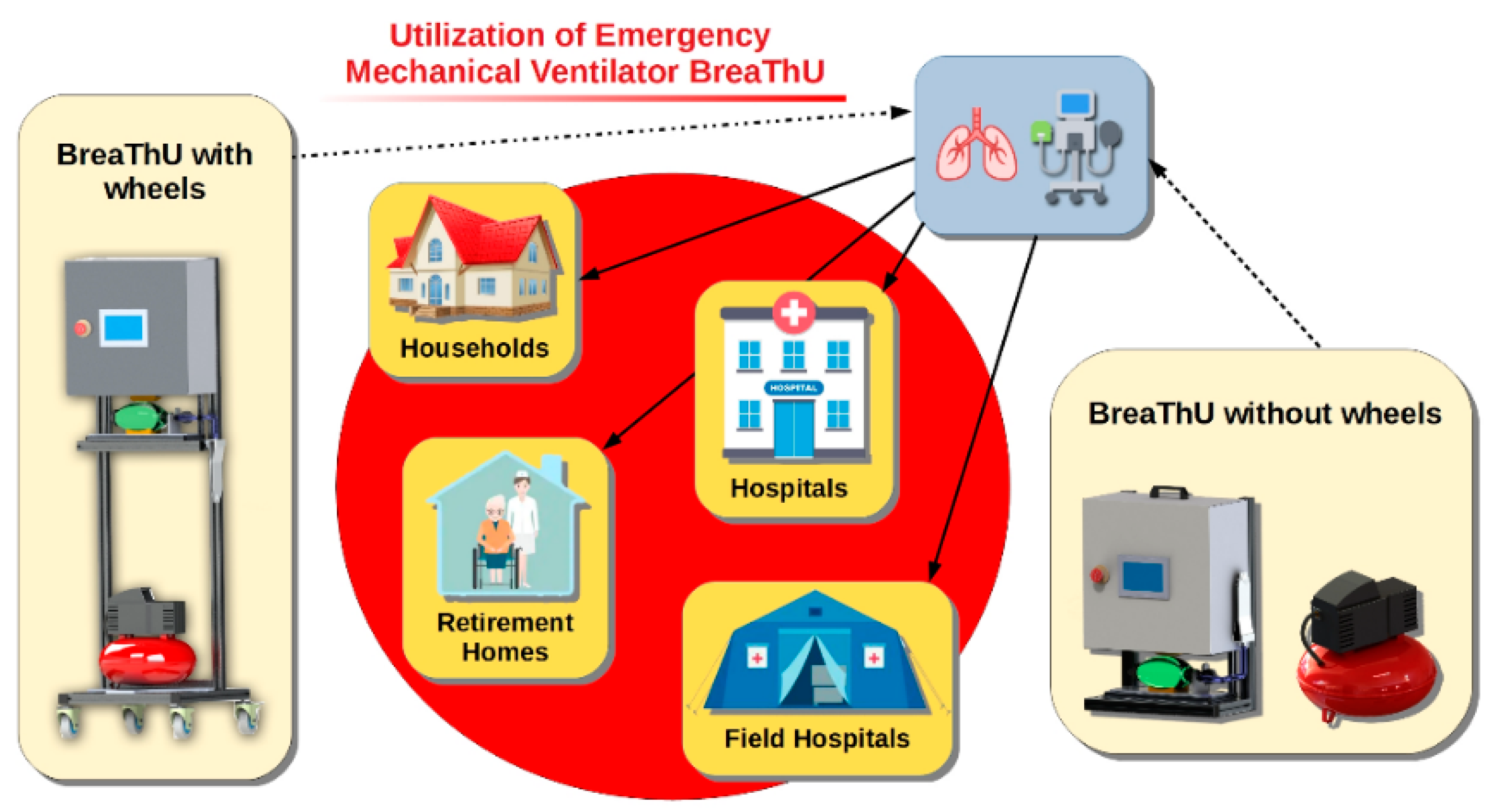
  • Portability—A mechanical design should offer an option to use a mechanical ventilator in hospitals or in households. Hence, the portability is an important property. A ventilator should be easily displaced from one to the next required place. In the case of need, the developed ventilator should also have the potential to be used in outdoor applications. For this reason, the ventilator BreaThU can be used as a version with wheels as well as without wheels, with consideration of manual transmission.
  • Simplicity—Considering today’s situation, the simplicity of the ventilator is one of the key elements. The ventilator consists of components which can be very easily replaceable. Some of the used components are printed by a three-dimensional (3D) printer and some of them are conventional industrial components which are commercially available. The simplicity of the ventilator ensures fast production of many other ventilators for the cases of unmanageable pandemic situations, when there may be a shortage of professional ventilators in the hospitals.
  • Fast reproducibility—Since one of the main aims of the ventilator BreaThU is utilization in very critical situations, the ventilator was designed to be quickly reproducible. For this reason, a mechanical and electrical design was adapted for this point.
  • Robustness—Mechanical robustness of the ventilator is an important point especially for outdoor applications, such as field hospitals.
  • Hospital, field hospitals and household utilization—As well as hospital utilization of the ventilator BreaThU, it also has potential to be applied in field hospitals and in households, especially for seniors.
  • IoT—The next important requirement for the ventilator was internet access ability. In this way, the data collected during the ventilation process can be collected and saved to a database. Subsequently, necessary statistics and analyses of the ventilation process of patients can be performed. There is also the possibility to set required ventilation parameters remotely.
The aim of this study was to develop universal a emergency mechanical ventilator, BreaThU, suitable for various environments, such as hospitals, field hospitals, households or retirement homes, see Figure 1. The ventilator BreaThU is adjusted to this requirement and it has been developed in two versions, one with wheels on a stand and the other without wheels for manual transmission.

3.2. Mechanical Design

The mechanism of AmbuBag compression is based on a proportional pneumatic system. Many hospitals in our country (Slovakia) have compressed air supply (0.5 MPa) within their buildings. For this reason, this system works based on a pneumatic-based mechanism. The main parts of the ventilator BreaThU are frame, air compressor, AmbuBag, sensors, cover box and PLC (Programmable logic controller) with touch screen, see Figure 2. The frame consists of Bosch Rexroth aluminum profiles which are suitable for fast assembling of constructions. They are standardly used in industry as a part of production lines. An air compressor serves as the energy supply for the pneumatic system.
As has been mentioned, the system uses AmbuBag, which is compressed by a double-acting pneumatic actuator. For the experimental verification of ventilator functions and suitability, the test lung has been used. As can be seen in Figure 2, there is the sensors interface between the test lung and inlet hose. This interface contains two sensors of pressure and two sensors of air flow. An operator can set necessary parameters through a touch screen. The operator is also able to check the measured parameters of ventilation such as pressure, air flow, tidal volume, etc.
The pneumatic system works via the following pneumatic scheme, shown in Figure 3.
Individual points of the scheme represent the following components: FR.1—manual pressure regulator, EP.1—E/P regulator (pressure control), EP.2—E/P regulator (air flow control), TH.1.1 and TH.1.2—silencers, V.1—5/3 pneumatic valve, R.1.1 and R.1.2—throttle valve, P.1—double-acting pneumatic linear actuator, and SP1, SP2 and SP3—end sensors. All pipelines in the designed pneumatic system are made from polyurethane. Connection pipelines between individual pneumatic components are as follows: Pipeline between compressor and FR.1 has length 2.1 m with inner diameter 4 mm, pipeline between EP.1 and EP.2 has length 0.65 m with inner diameter 4 mm, pipeline between EP.2 and V.1 has length 0.38 m with inner diameter 4 mm and pipelines between V.1 and P.1 have length 0.42 m with inner diameter 2 mm.

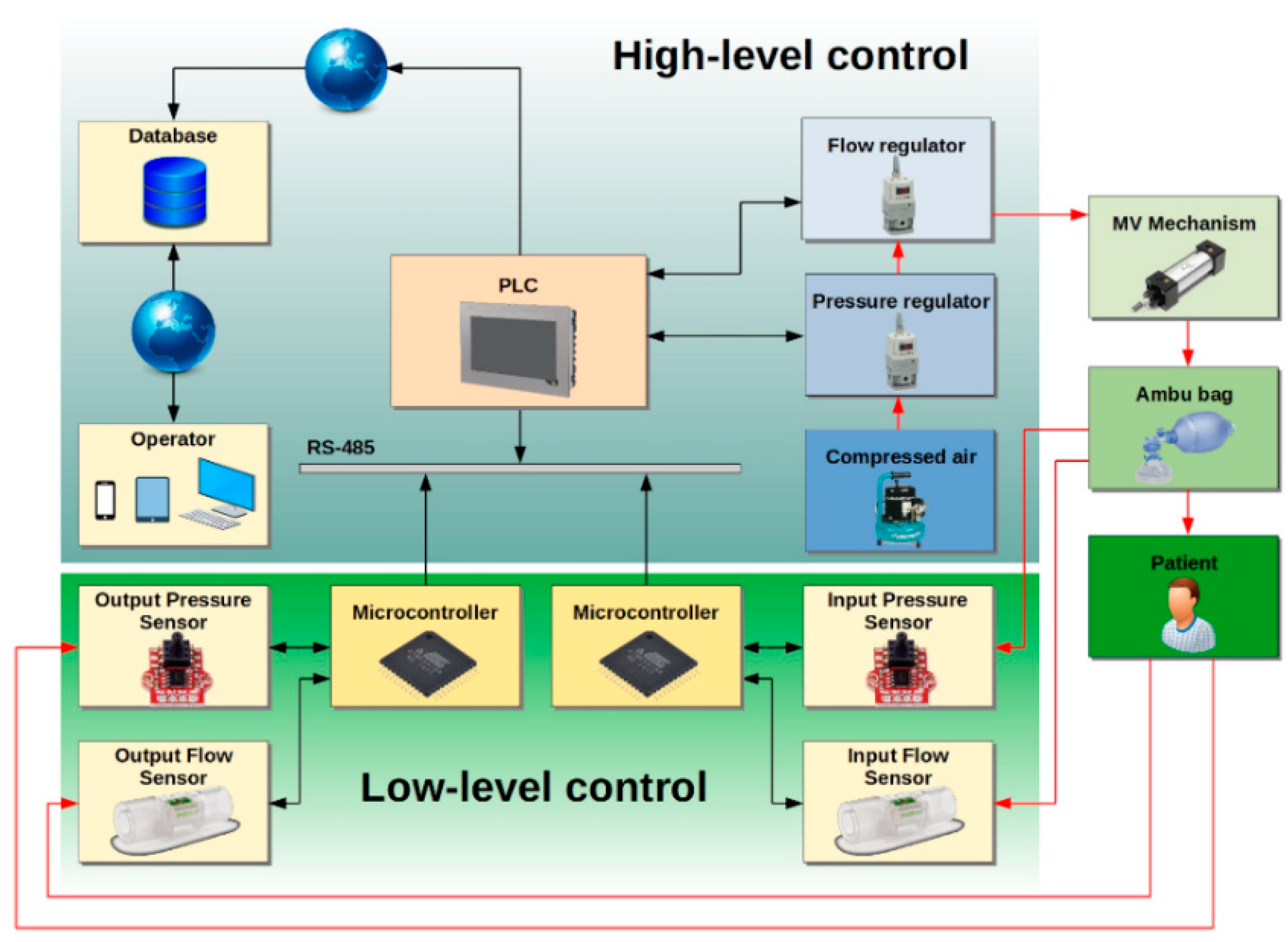
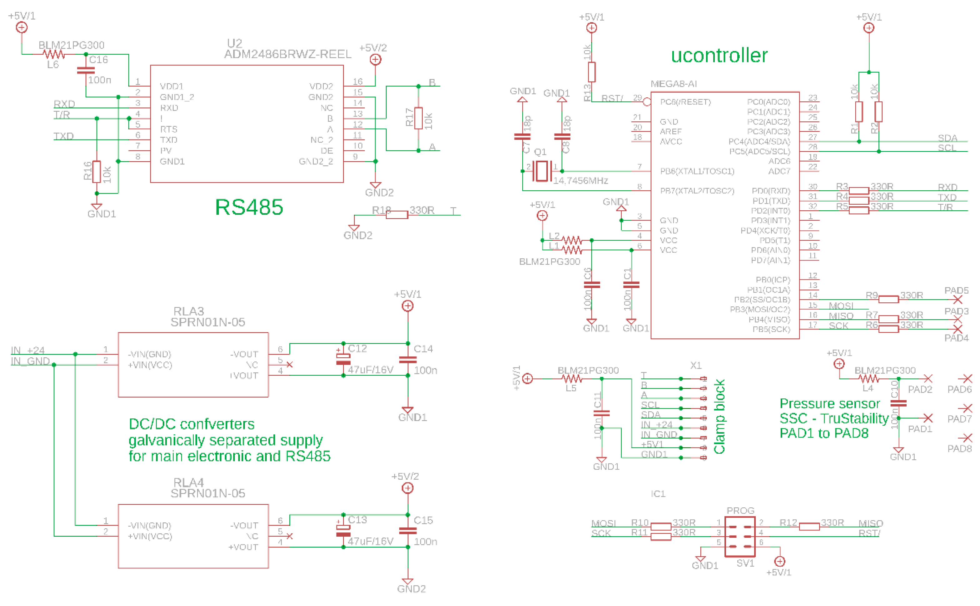
3.3. Hardware Design

The control system of the mechanical ventilator BreaThU works on two levels. The first one is low-level and the second is high-level. The low-level control system is based on the microcontroller Atmel ATxmega16E5, which communicates with pressure and flow sensors [19]. The ventilator uses the pressure sensor SSCDLNN040MGSA5, which has SPI output, and the air flow sensor SFM3300-250, communicating with the microcontroller through I2C. ATxmega16E5 works on frequency 32 MHz. The microcontroller processes data from sensors and transmits them with frequency 500 Hz through RS-485 to PLC. The high-level control system works on PLC B&R 4PPC70.0702-20W. The PLC receives the data from the microcontroller, and by using the fuzzy control algorithm, it controls the pneumatic cylinder, which compresses AmbuBag. The aim of the designed algorithm is positioning of the pneumatic cylinder in order to achieve the desired pressure or tidal volume [20,21]. The system works with constant supply pressure with a value of 0.45 MPa, which is achieved by the electro-pneumatic regulator SMC ITV1050-31F2N, EP.1 from Figure 3. The air flow, which flows to the pneumatic actuator, is controlled by the electro-pneumatic regulator ITV3050-03F4BN2-X15, EP.2 from Figure 3. The concept of the whole system is shown in Figure 4. The data signals are denoted by black color. There is also the possibility to connect PLC to the internet and send the data from the ventilator to a database. Subsequently, these data can be monitored or processed by the user through PC, tablet, mobile phone, etc. HMI (human–machine interface) offers a clear and simple environment, which ensures comfortable service. An operator has several options of how to adjust the ventilation process. At first, it is possible to set a pressure of inspiration and expiration in cmH2O units. The next important parameter is time of inspiration and expiration phase. A real-time course of individual parameters may be watched on the HMI. The electrical scheme of low-level control is shown in Figure 5.

3.4. Control Modes of the Ventilator

The ventilator BreaThU is able to work in two modes. The first mode works on the basis of reference pressure tracking (RPT). RPT mode can be divided into two or four phases. During the first phase, the pressure increases up to the value of reference pressure. After achieving the required value of pressure, the pressure is maintained at this value to the end of inspiration time. Subsequently, the pressure decreases to the PEEP value and then the pressure is maintained at this value to the end of expiration time. Then, it follows the next cycle of breathing.
The second mode is adaptable breathing mode (ABM). ABM serves only as support for patients without difficult disease state without pulmonary pathology. ABM is based on an air flow sensor. When a patient starts breathing, the sensor measures a positive flow, and the ventilator starts providing tidal volume to the patient. When a patient starts to exhale, the air flow sensor measures negative flow, and the ventilator is not active. The sensitivity of the ventilator, which is the reaction on positive measured flow, can be set by the operator. Both modes will be experimentally verified within the experimental section of this paper.

4. Design of Control System

The previous section introduced the control modes of the ventilator. This section provides the background of the designed control system for RPT ventilation mode. The main limitation of the investigated system, from the view of control, is utilization of AmbuBag as a source of pressure/tidal volume. The problem formulation and control system design will be discussed in the following sections.

4.1. Problem Formulation

Considering RPT ventilation mode, the aim of the developed control system is to control required pressure in patients’ lungs using AmbuBag, which is compressed by a pneumatic actuator. In other words, it is necessary to control air flow to a pneumatic actuator by which is AmbuBag compressed. The main problem is to obtain the required pressure of AmbuBag for the required time, since the character of AmbuBag is not very suitable for control purposes. By gradual compressing of AmbuBag, the output pressure also increases. However, after very subtle release of AmbuBag, the pressure decreases rapidly, see Figure 6. The compression of AmbuBag causes the gradually increasing pressure, up to roughly 30 cmH2O. However, by very little release of AmbuBag, the piston of the actuator was released roughly only 2 mm, and the pressure of AmbuBag decreased rapidly. The blue line in Figure 6 represents the moment when the piston of the actuator was released. The pressure decreased from 30 to only 13 cmH2O. Subsequently, the pressure was only decreasing without any motion of the pneumatic actuator.
The effect described in Figure 6 causes problems during the control of pressure, because the pressure can be controlled only from the smaller to the higher value of pressure. In other words, the pressure has to be a monotonically increasing function during the inspiration phase. After overshooting the required value of pressure, it cannot be controlled to a lower value of pressure. The lower value of pressure can again be controlled in the next phase of breathing, when the pneumatic actuator is fully retracted and subsequently extended. It means that any oscillating course of pressure is inadmissible. For this reason, the control algorithm of RPT mode has to be designed with a focus on these issues.

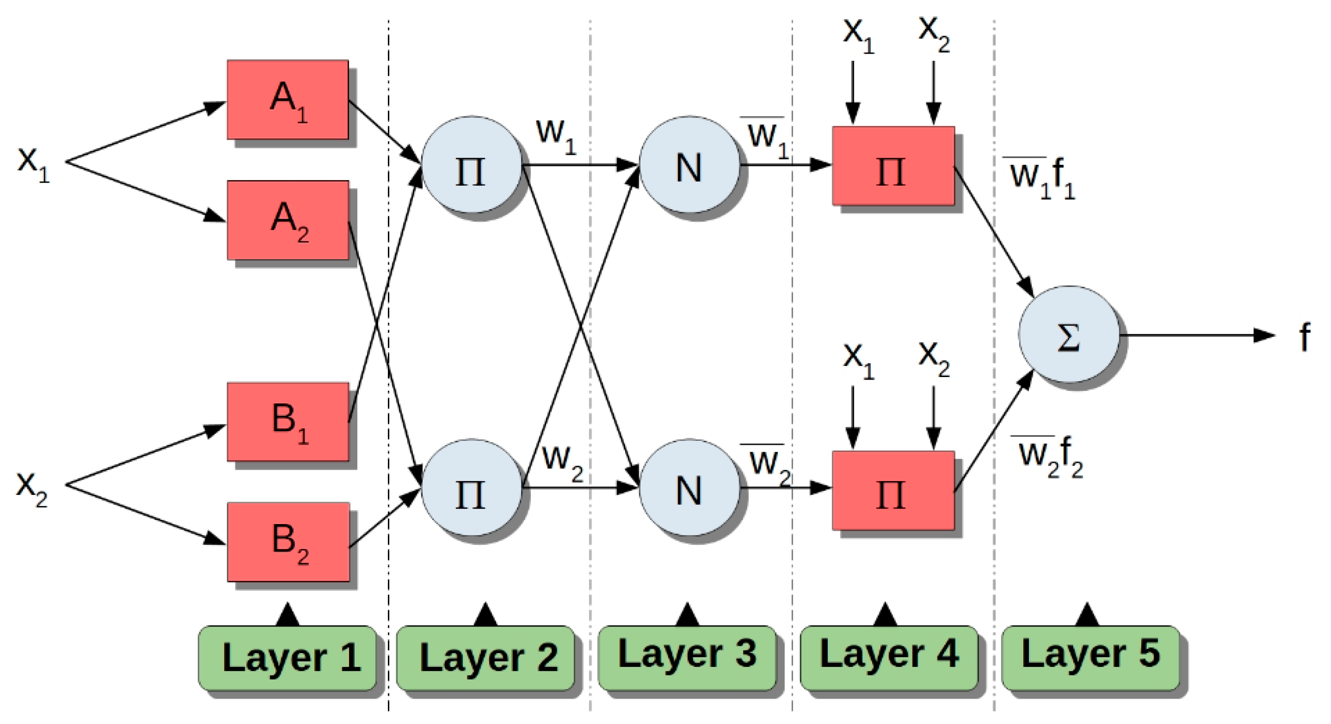
4.2. Adaptive Neuro-Fuzzy Inference System

The control algorithm for the ventilator BreaThU is designed as an adaptive neuro-fuzzy controller. An adaptive neuro-fuzzy inference system (ANFIS) is a feed-forward neural network developed by Jang [22] which gives relations between input and output data to determine an optimal membership function. An artificial neural network and fuzzy logic model creates ANFIS architecture consisting of five different layers, see Figure 7. In this study, the architecture of ANFIS is based on the first-order Takagi–Sugeno model [23]. The individual layers of ANFIS have the following meaning.
Layer 1: Fuzzification layer. All nodes in layer 1 are adaptive nodes. The outputs of this layer are the fuzzy membership grades of the inputs, given by:
O i 1 = μ A i ( x 1 ) ,   i = 1 ,   2
O i 1 = μ B i 2 ( x 2 ) ,   i = 3 ,   4
where x 1 and x 2 are input variables to node i, A i and B i are the linguistic labels associated with this node and μ ( x 1 ) and μ ( x 2 ) are membership functions (MFs). There are many MFs that can be used, such as Gaussian-shaped function, trapezoidal function, gamma function and others.
Layer 2: In comparison with the previous layer, the nodes in this layer are fixed. The output of the i-th node can be expressed as:
O i 2 = w i = μ A i ( x 1 ) · μ B i ( x 2 ) ,   i = 1 ,   2 ,  
where w i represents the firing strength of a rule and O i 2 is output of the layer 2.
Layer 3: Normalized layer. Every node in this layer is considered a fixed node. The normalized firing strengths are given by:
O i 3 = w ¯ = w i w 1 + w 2 ,   i = 1 ,   2 ,  
where O i 3 is output of layer 3 and w ¯ is normalized firing strength.
Layer 4: Adaptive layer, with output function:
O i 4 = w ¯ i f i = w ¯ i ( p i x 1 + q i x 2 + r i ) ,   i = 1 ,   2 ,  
where p i , q i and r i are so-called consequent parameters.
Layer 5: Output layer. Every node in this layer is a fixed node. The output of this layer is:
O i 5 = i w ¯ i · f i = i w i · f i w i
Considering all ANFIS layers, one has premise parameters { a i ,   b i ,   c i } —parameters given by MF—and { p i ,   q i ,   r i } , labeled as consequent parameters. The aim of the training algorithm is to tune premise and consequent parameters in order to make the ANFIS output match the training data [24]. There are several learning techniques which could be used such as backpropagation [25], computing error signals recursively from the layer 5 output backward to the input nodes (layer 1), or genetic algorithm (GA) [26]. In this study, a hybrid learning algorithm will be adopted, which is highly efficient in training the ANFIS system [27].
A hybrid learning algorithm is a combination of the backpropagation gradient descent method and the least-squares method and is used for training FIS (Fuzzy Inference System) membership function parameters to emulate a given training dataset. The backpropagation gradient descent method is used for optimization of the premise parameters described above. On the other hand, the least-squares method is used for optimization of consequent parameters. The consequent parameters are used for calculation of ANFIS output. By applying the hybrid learning algorithm, node outputs go forward until layer 4 and consequent parameters are determined by the least squares [28]. The output can be expressed as:
f = w 1 w 1 + w 2 f 1 + w 2 w 1 + w 2 f 2
f = w ¯ ( p 1 x 1 + q 1 x 2 + r 1 ) + w ¯ ( p 2 x 1 + q 2 x 2 + r 2 )

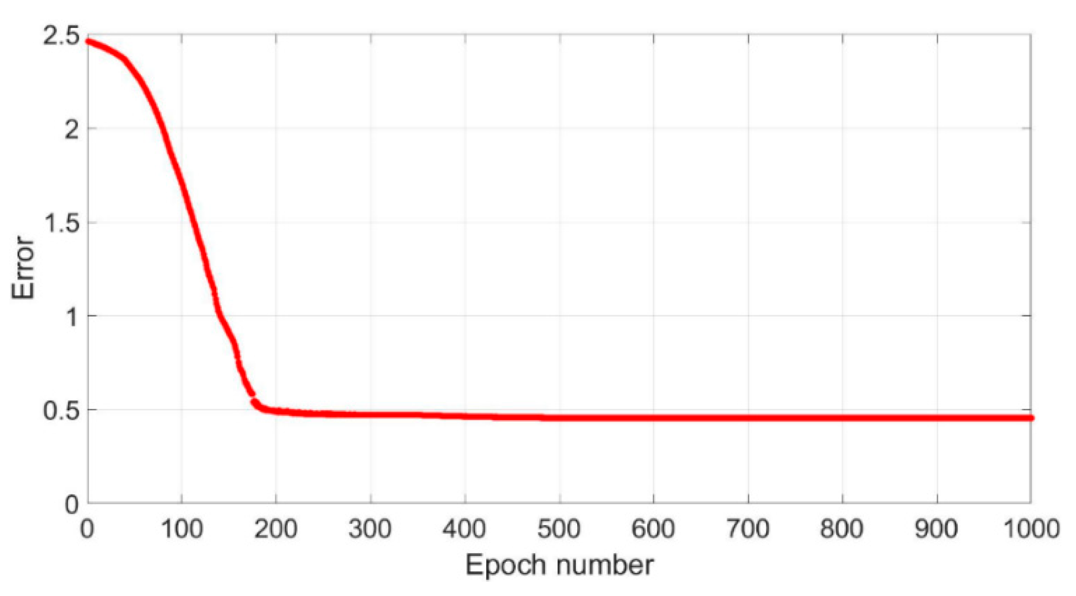
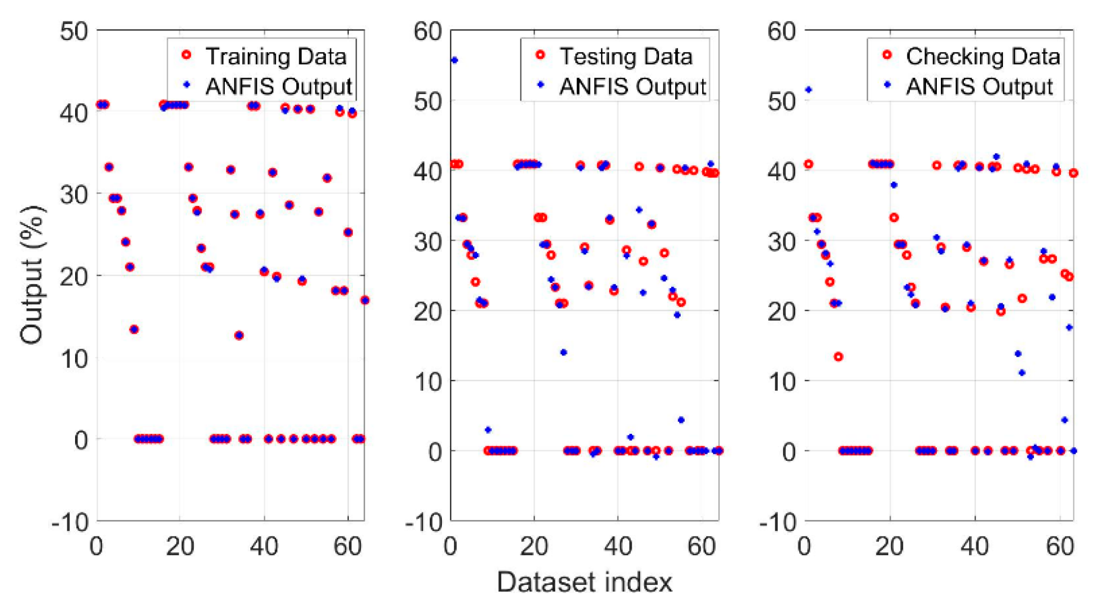
4.3. Collecting Data and Training Process

Considering the problem formulation, we have designed the system for RPT mode as follows. The system will have three inputs, namely control error   e ( t ) , speed error d e ( t ) and reference pressure p r e f ( t ) , and one output, which is air flow, f c t l , to the pneumatic actuator. The control error and speed error are defined as:
e ( t ) = p r e f p a c t
d e ( t ) = d ( p r e f p a c t ) d t
where p r e f is reference pressure and p a c t is actual pressure measured by the sensor. Considering the conventional controlled system, such as DC motor with a focus on angular velocity control, the inputs for ANFIS should be only control error and speed error [29], whereas it does not matter in principle if there is a positive or negative control error e ( t ) . In the case of AmbuBag, the situation is different. Consider Figure 8: when a negative control error e ( t ) occurs during the inspiration phase (overshooting of the reference pressure), the air flow to the pneumatic actuator has to be stopped. It should be noted that air flow has to be stopped earlier than when the negative control error occurs due to transport delay. On the other hand, when a negative control error occurs during the expiration phase, the air flow is gradually subtly decreased in order to track the reference pressure signal. To correctly handle the control error, e ( t ) , there is a need to identify which phase of the reference pressure is in progress. For this reason, along with control error and speed error, it is necessary to consider the next control input for the ANFIS training process, which is reference pressure, p r e f ( t ) .
The key element in the training process is obtaining suitable training data for ANFIS. In this case, it is necessary to collect the set of training data denoted by training matrix T r   ×   c , where r represents number of measured data and c is sum of input and output parameters; in our case, c = 4 . We define the training matrix as T = [ e , d e ,   p r e f , f c t l ] r   ×   c , where vector of control error is e = [ e 1 , , e r ] T r , vector of speed error is d e = [ d e 1 , , d e r ] T r , vector of reference pressure is p r e f = [ p r e f 1 , , p r e f r ] T r and vector of control output is f c t l = [ f 1 , , f r ] T r .
The training data, T r   ×   c , need to be collect by any algorithm. For this purpose, the algorithm based on the IF-THEN structure for collecting the training matrix, T ,   has been designed. The data have been collected for various values of reference pressure, p r e f , changing from 15 up to 30 cmH2O. The control output, f c t l , has been modified during the collecting process for each reference pressure, so that the measured pressure did not cross the reference pressure. The aim was to achieve a monotonically increasing time course of pressure. In other words, it is necessary to avoid overshooting of the reference pressure. The training process worked according to Algorithm 1.
Algorithm 1: Data Collecting.
1: Setting of initial parameters of ventilation
2: WHILE (collecting Process is Alive = true)
3:  Measuring of control error e ( t ) and speed error d e ( t )
4:  IF e ( t ) e 0 , e 1
5:   set the output control f c t l
6:  ….
7:  ELSEIF e ( t ) e N 1 , e N
8:   set the output control f c t l
9:  END_IF
10:  IF [ m a x ( p a c t ) > p r e f ]   AND   [ i n s p i r a t i o n P h a s e = t r u e ]
11:   decrease μ
12:  ELSE
13:   increase μ
14:  END_IF
15:   f c t l = μ · f c t l
16: END_WHILE
where μ is modifiable coefficient { μ + | μ 0 } . When maximal value of pressure, p a c t , measured during one breathing cycle (in the inspiration phase), overshoots the reference pressure, p r e f , the coefficient, μ , is manually changed to the lower value. On the other hand, when maximal measured pressure, p a c t , during the breathing cycle is lower than the reference pressure, the coefficient, μ , is manually changed to the higher value. This process is repeated until the reference pressure, p a c t , equals to p r e f . Subsequently, the coefficient for the expiration phase is also modified in the same way. When the time course of the breathing cycle is approximately in accordance with the reference pressure, the measured data consisting of three input variables and one output variable are collected. With the presented algorithm, all input–output pairs necessary for the training process were collected.
After the collecting process follows a training process. Measured data, in the form of training matrix, T r   ×   c , have been used for training in MATLAB R2019b using the ANFIS toolbox. There have been several structures of ANFIS designed with changing amounts of membership functions for individual input variables. There have been only triangular and trapezoidal membership functions considered due to their simplicity. Since the control system has to be used for real-time application, there have not been any computationally intensive types of membership functions used. In this paper, ANFIS is based on a Sugeno-type fuzzy inference system with singleton output membership functions that are constant.
The parameters of training are as follows: Error tolerance is 0, epochs 4000 and optimization method is hybrid.
The following Table 1 and Table 2 show training errors for individual types of membership functions and for changing number of membership functions. The results are shown as percentage error. In Table 1, the numbers of membership functions for control error and speed error are the same. In Table 2, the number of membership functions for control error is twice the number of speed error membership functions. Both tables use two membership functions for reference pressure. Assuming three membership functions (MF) for the reference pressure, the results were the same.
The comparison of individual results is shown in Figure 9. The meaning of individual legends from Figure 9 is as follows: Triangular 1—the same number of triangular membership functions for control error and speed error, Triangular 2—number of triangular membership functions for control error is twice the number of speed error triangular membership functions, Trapezoidal 1—the same number of trapezoidal membership functions for control error and speed error, Trapezoidal 2—the number of trapezoidal membership functions for control error is twice the number of speed error trapezoidal membership functions. In the case of an odd number of control error membership functions, the speed error is rounded up. As can be seen from Figure 9, trapezoidal membership function provides better results in comparison with triangular membership function. By comparison of Trapezoidal 1 and Trapezoidal 2, the results are not dramatically different. For this reason, the set of Trapezoidal 2 membership functions will be used, since they use a lower number of speed error membership functions. This solution is more suitable from the view of real-time application, while there will be a lower number of rules for the fuzzy controller.
Based on the results offered in Table 1 and Table 2, an ANFIS structure with 14 membership functions for control error, 7 membership functions for speed error and 2 membership functions for reference pressure was chosen. The training process of the ANFIS structure 14–7–2 is shown in Figure 10. The output is set to be constant. In Figure 11, the process of training, testing and checking is shown. The influence of individual inputs to final output can be seen in Figure 12, Figure 13 and Figure 14. As can be seen, the main contribution to the control output is the control error and reference pressure. Figure 15 presents the membership functions of control error, speed error and reference pressure with structure 14–7–2. Figure 15 considers both the initial membership functions and membership functions after the training process for all input variables. The trapezoidal membership function is defined in Appendix A.
By consideration of structure 14–7–2, one gets 196 rules for the fuzzy controller, which are based on logical conjunction. The control system of the mechanical ventilator will use Algorithm 2 with the assumption of fuzzy rules.
Algorithm 2: Fuzzy rules.
1: WHILE (ventilationProcess==isAlive)
2:  Resetting previous states, order = 0
3:  Determination of input variables: e, de, pref
4:  Fuzzification
5:  FOR er=1:14
6:   FOR se=1:7
7:    FOR rp=1:2
8:     order = order + 1
9:     IF e==eMF[er] AND de==seMF[se] AND pref==rpMF[rp]
10:      output = outputMF[order]
11:     END_IF
12:    END_FOR
13:   END_FOR
14:  END_FOR
15: END_WHILE
The cycle WHILE represents the main loop of the ventilation process. At first, all previous states of fuzzification are reset. The variable “order” serves for determination of the constant output value. In this case, there are 196 output values. The fuzzification means transforming a crisp quantity into a fuzzy quantity, which is based on Figure A1 and Equation (A1), see Appendix A. The rules of the trained fuzzy controller are processed by three nested cycles FOR and structure IF. Variables eMF, seMF and rpMF represent the results of fuzzification for control error, speed error and reference pressure, respectively.

5. Simulations and Experiments

This section provides simulation and experimental analysis of mechanical ventilation. At first, the mathematical description of AmbuBag volume change depending on its compression is introduced. Subsequently, the characteristics of AmbuBag are investigated. The pressure of AmbuBag is expressed depending on compressing force acting on AmbuBag. The output of the training process results in a fuzzy controller which will be verified by the simulation model as well as by experiments.

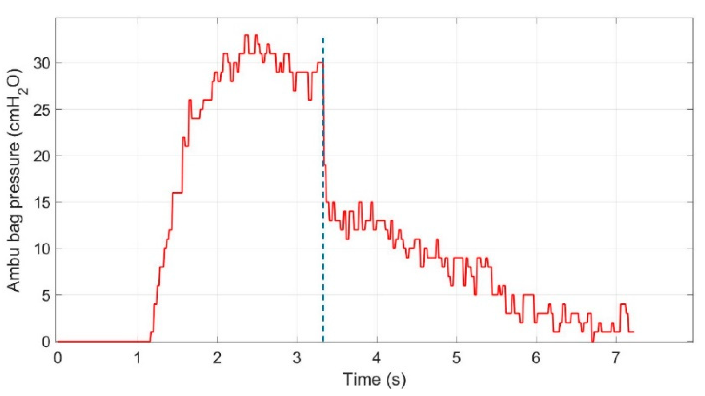
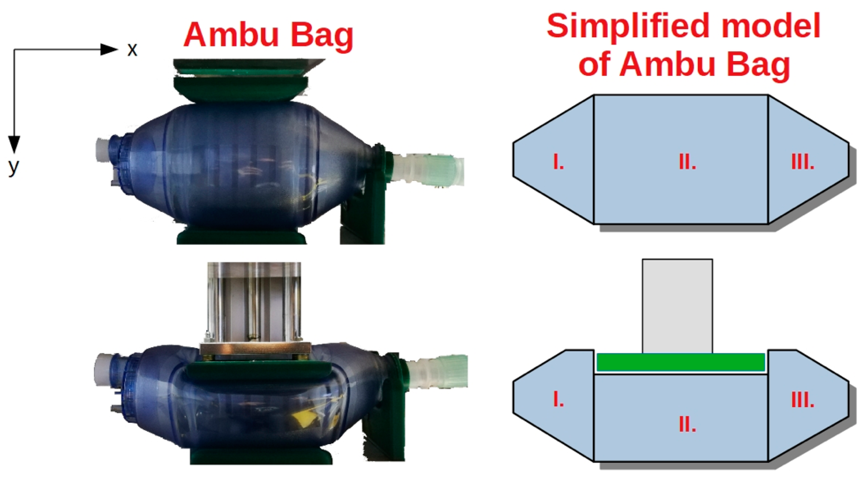
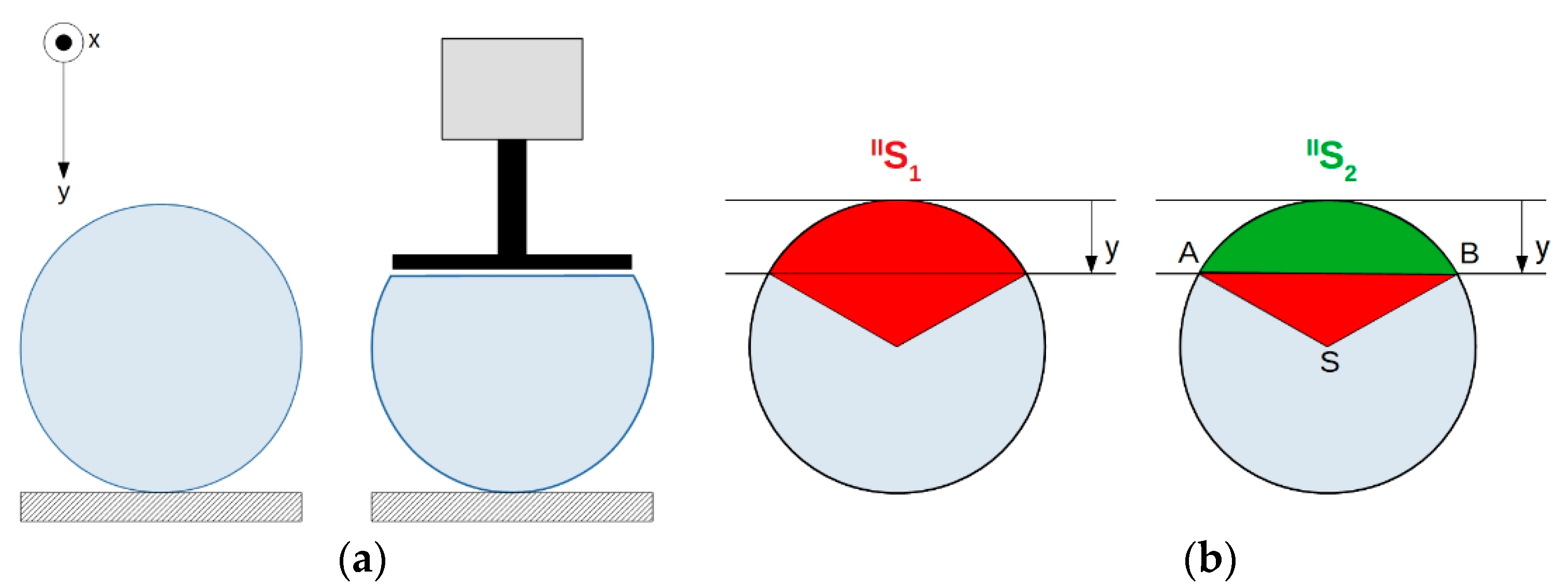
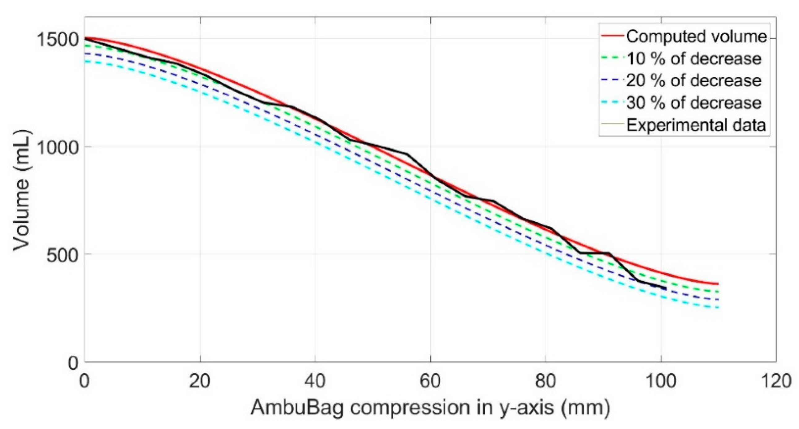
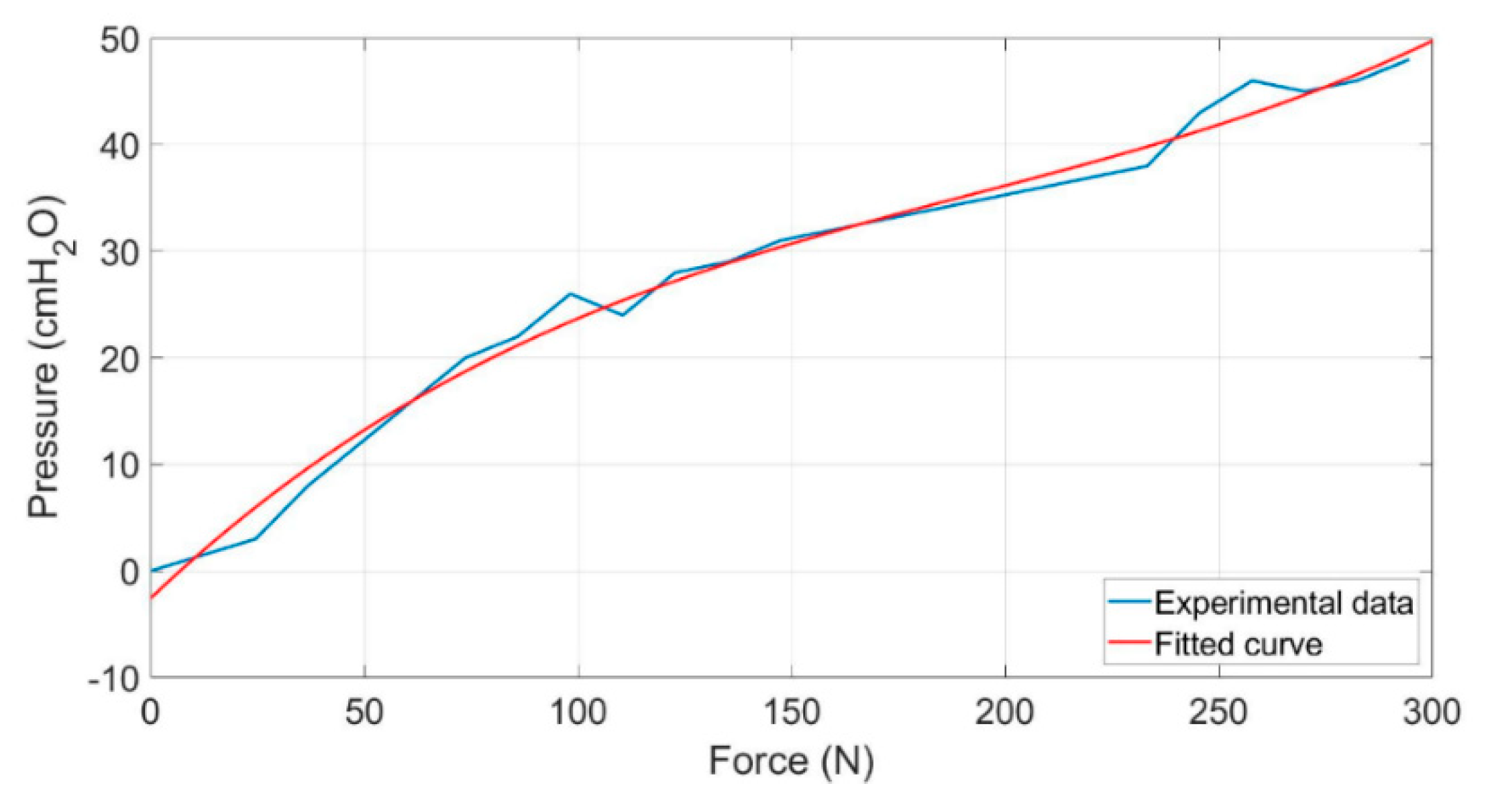
5.1. Mathematical Description and Experimental Analysis of AmbuBag

The following section presents the mathematical description and experimental analysis of AmbuBag. The relation between the changing volume of AmbuBag depending on the pneumatic actuator piston extension will be shown. Let us consider Figure 16.
The presented Ambubag can be divided into three parts: parts I and III can be replaced by a truncated cone and part II can be replaced by a cylinder. As can be seen from Figure 16, the deformation of parts I and III seems to be not so obvious, compared to the deformation of part II. Next, by consideration of the small volume of air in parts I and III, in comparison with part II, the deformation of parts I and III is neglected during the compression of AmbuBag. For this reason, this analysis is based on the idea that during compression of AmbuBag, mainly the cylindrical part II is deformed.
The following section analyzes how the volume of part II changes depending on its compression. The compression is expressed by extension of the actuator piston in the y-axis, see Figure 17.
Let us consider part II of AmbuBag with perpendicular view in the x-axis direction, see Figure 17a. The pneumatic actuator compresses AmbuBag and it deforms its shape approximately, as it is shown in Figure 17a. To compute the volume of part II after deformation, let us consider Figure 17b. The deformed area is II S 2 (green color) and the final area after deformation can be expressed as:
S I I = π r 2 ( S I I 1 S Δ )
where S Δ represents the area of triangle ASB. The auxiliary calculations are given in Appendix B. The residual volume of AmbuBag after compression can be expressed as the sum of all three parts of the simplified model of AmbuBag:
V = V I + V I I + V I I I
where V I and V I I I can be simply calculated as the volume of truncated cones and V I I is
V I I = L [ π r 2 2 + r 2 asin θ + ( r y ) r 1 θ 2 ]
where L is the length of part II of AmbuBag in the direction of the x-axis and θ = ( r y ) / y . Equation (13) can be applied for the case when deformation of part II in the y-direction is lower than the value of radius, r . On the other hand, Equation (13) assumes θ . An approximated mathematical description of air volume in AmbuBag was also experimentally verified. The results are shown in Figure 18. Except for mathematical expression of residual volume of AmbuBag (red color) and experimentally determined residual volume (black color), there are also curves, which express the residual volume of AmbuBag, with consideration of deformation of parts I and III. Figure 18 considers 10% (green color), 20% (purple color) and 30% (blue color) deformation of parts I and III of AmbuBag.
Based on this analysis, the residual volume of AmbuBag can be approximately determined depending on its compressing force, V = f ( y ) .

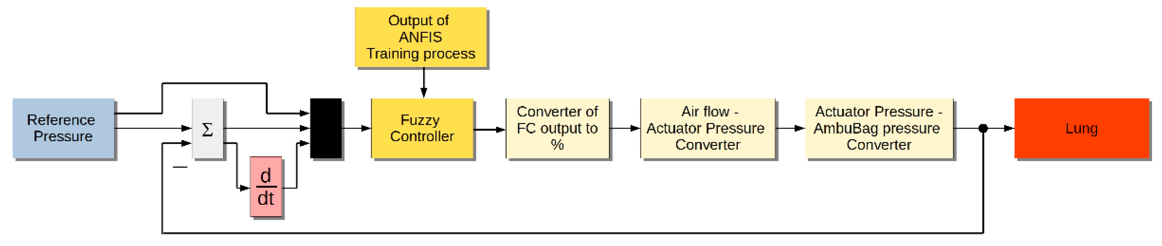
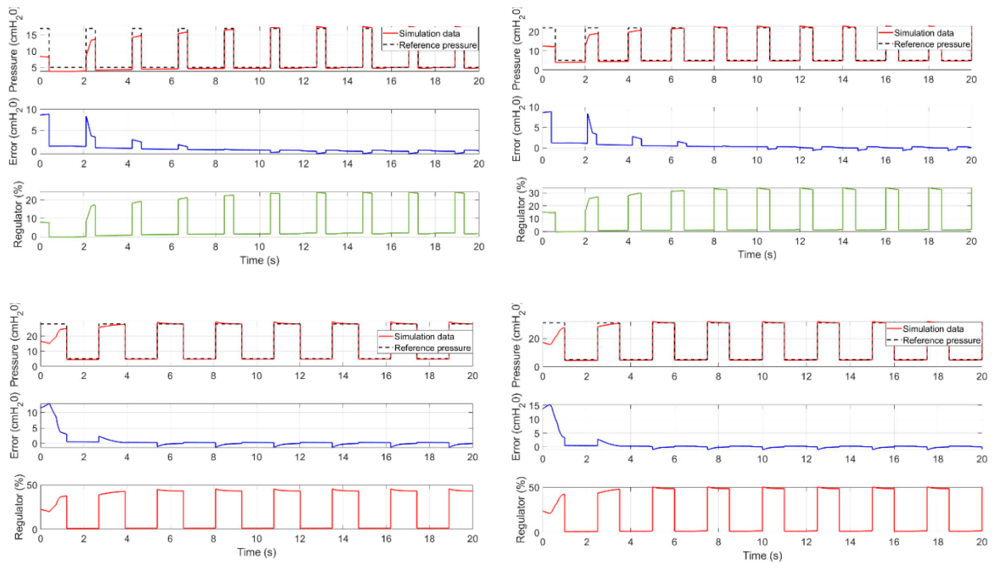
5.2. Simulation Model
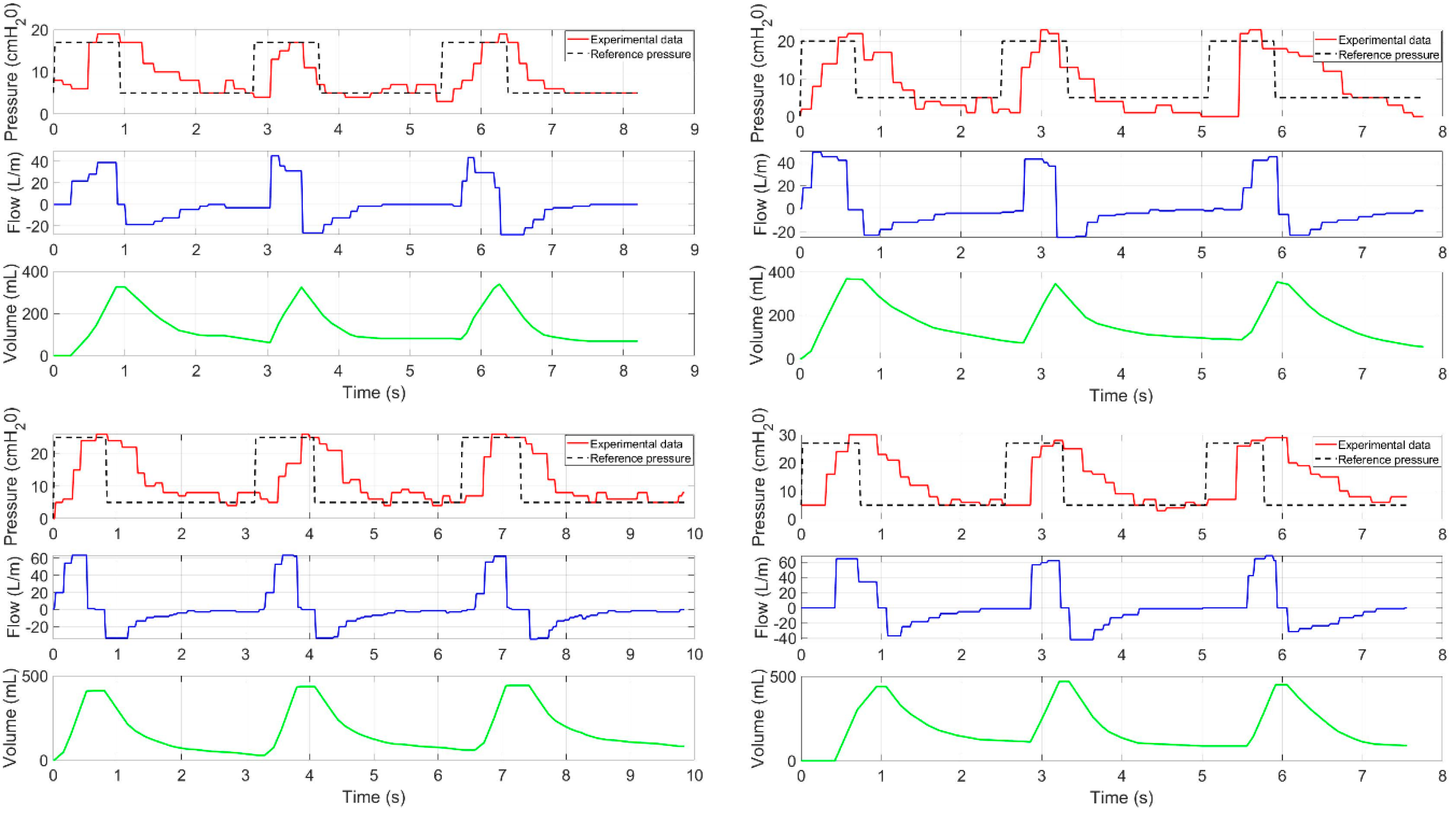
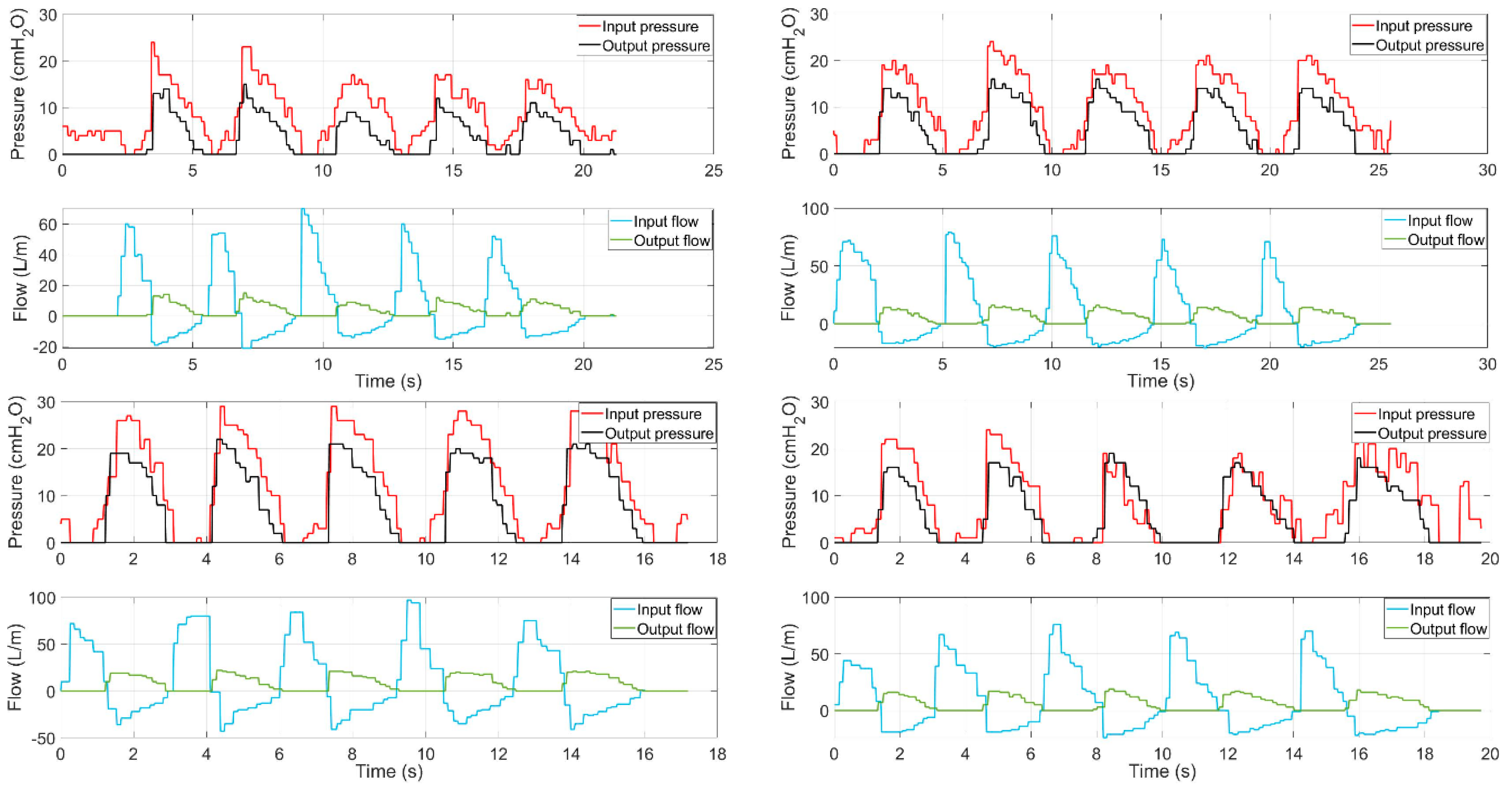
First, the relation between compressing force and the pressure of AmbuBag is introduced. This analysis will then be used for the creation of the simulation model.
From the pneumatic scheme shown in Figure 3, pressure regulator EP.1 follows constant pressure, within this application set to be 0.45 MPa. Regulator EP.2 controls an air flow through the pneumatic valve V.1 to a pneumatic actuator P.1. Based on the magnitude of air flow to the pneumatic actuator, the AmbuBag is compressed and its pressure increases. The main point now is to determine a relation between controlled air flow of EP.2 and pressure at the end of the last point of the breathing device, which is entry into the patient’s mouth.
First of all, from the datasheet of EP.2 (ITV3050-03F4BN2-X15), the relation between percentage opening of regulator and its output pressure is expressed, see Figure 19. The relation is derived for our case assuming the maximum input pressure of 0.5 MPa. The relation between input percentage opening of the air flow regulator and its output pressure can be expressed by the following equation:
p E P 2 = 0.5 x 100
where x represents percentage opening of regulator EP.2. The final point to build the simulation model is determination of the relation between force compressing AmbuBag and its output pressure. The relationship is shown in Figure 20.
The blue color denotes experimental data while the red color denotes the fitting curve to experimental data. The fitting curve can be described by polynomial of the third order, see Equation (15):
f = 0.2943 x 3 3.46 x 2 + 18.71 x 2.556
The coefficient of determination of Equation (15) is R 2 = 0.9878 . The following Figure 21 shows the control scheme of the simulation. The reference pressure varies according to principles of inspiration and expiration phases described in previous sections of the paper. Using MATLAB 2019b ANFIS toolbox and training data, the fuzzy controller (FC) was determined. The result of the training process is the fuzzy controller with three inputs, namely control error, speed error and reference pressure. The output of the fuzzy controller is opening of air flow regulator with analog value with consideration of value −215 for a 0% opened regulator and value +215 for a 100% opened regulator. The output of the FC is subsequently converted to percentage value. The next block assumes Equation (14) describing the relation between percentage opening of the regulator and output pressure of the regulator. The last point of the control scheme is the model of AmbuBag with input force affecting AmbuBag and output pressure coming to the patient’s lung.
The simulation model works with fixed-step time of 0.001 s and simulation lasts 20 s. The simulations consider the reference pressure of 17, 22, 28 and 31 cmH2O. The PEEP value is set to be 5 cmH2O for all simulation cases. In Figure 22, the time course reference pressure and controlled pressure, control error and control output of regulator EP.2 are shown.
As can be seen from Figure 22, the controlled pressure tracks the reference pressure after two cycles of breathing. The simulated fuzzy controller will be now used for the RPT mode of the mechanical ventilator.

5.3. Experiments

The aim of this section is experimental verification of the designed control algorithm. The experiments are focused on two objectives: The first objective of the experiments is to verify the tracking of a reference pressure according to the positive pressure ventilation principles described above. The main aim is to verify the functionality of the designed control algorithm for RPT mode with the trained fuzzy controller. In other words, the possibility of reference pressure tracking by AmbuBag in combination with the pneumatic actuator and proportional pneumatic regulator will be analyzed. This analysis also provides the view on the suitability of the used approach (ANFIS) for AmbuBag.
The second objective of the experiments is the analysis of ABM mode, as described in Section 3. During ABM mode, four different kinds of breathing were tested, with different frequency and depth of breathing. The experiments also consider different sensitivity of ABM for individual breathing cases. The optional sensitivity of AMB mode ensures in which moment the ventilator should start to assist the patient. The higher sensitivity means that the ventilator starts to assist the patient for very low values of measured positive air flow.
The results of the experiment are shown in Figure 23 and Figure 24. Within the experiments, the following reference pressures have been used: 17, 20, 25 and 27 cmH2O. For all cases, PEEP with a value of 5 cmH2O was used. As can be seen in Figure 23, the controlled pressure roughly tracks the reference pressure. There are also peaks of pressure, however they do not exceed 2–3 cmH2O. There is also time offset of controlled pressure in comparison with reference pressure, which is caused by the transport delay of the pneumatic system. The main problem during the experiments was holding the PEEP value of the pressure at 5 cmH2O, which is caused by the characteristics of AmbuBag and also by the non-hermeticity of the printed sensor interface. This problem occurs mainly in the cases of lower values of reference pressure during the inspiration phase. However, the developed mechanical ventilator offered satisfactory results. In RPT mode, it was able to hold the ratio of inspiration/expiration according to the requirements described in Section 3. The ventilator was also able to deliver the required tidal volume.
In Figure 24, the experimental results from assisted breathing mode are shown. In the figure, input and output measured values are shown. Input pressure and input air flow are measured before entering the patient’s mouth. On the other hand, output pressure and output air flow are measured in the second hose, which leads the exhaust to the surrounding environment. From the results presented in Figure 24, it can be seen that there is slightly lower output air flow in comparison with input air flow. The reasons for this are a not quite perfectly printed sensor interface by the 3D printer, and a not perfect seal of individual interface parts with sensors. However, these issues do not have any serious impact on the functionality of the mechanical ventilator.

6. Conclusions

In this paper, a mechanical ventilator based on AmbuBag and pneumatic systems was presented. We introduced the requirements of the mechanical ventilator from the view of ventilation control and also from the view of mechanical design. The main contributions of the paper are as follows: the new concept of the mechanical ventilator, the development of a control algorithm, which is based on an adaptive neuro-fuzzy inference system, and the mathematical description and experimental analysis of AmbuBag. The paper also offered a detailed description of the simulation model.
The results of experiments offered the following conclusions: The introduced approach, which is based on the ANFIS controller, provided satisfactory results of the mechanical ventilation. The ventilator was able to roughly track the reference pressure. For this reason, it can be stated that the approach is suitable for use. It is also able to meet requirements such as the possibility of pressure control ventilation, inspiration/expiration ratio or delivery of tidal volume. The experimental results showed that the main problem was in maintaining the PEEP value of pressure, which is caused by the characteristics of AmbuBag and also by the non-hermeticity of the printed sensor interface. These problems occurred especially for the cases of low values of reference pressure during the inspiration phase. The paper also introduced the results from assisted breathing mode ventilation, which serves as only support for patients without pulmonary pathology.
The mechanical ventilator BreaThU is ready for biological testing. The future work will be focused on the animal tests. The vital functions of the animal will be monitored during the ventilation. Consequently, the results will be analyzed, and necessary changes will be made in order to be used for human patients.

Author Contributions

Conceptualization, J.Ž., M.K. and I.V.; methodology, M.K. and I.V.; software, I.V. and M.S.; validation, I.V.; formal analysis, M.K., P.M., J.L. (Ján Liguš) and P.T.; investigation, P.M., J.L. (Jana Ligušová) and P.T.; writing—original draft preparation, I.V.; supervision, J.Ž. and M.K.; project administration, I.V. All authors have read and agreed to the published version of the manuscript.

Funding

This research was funded by Slovak Grant Agency—project KEGA 030TUKE-4/2020.

Institutional Review Board Statement

Not applicable.

Informed Consent Statement

Not applicable.

Data Availability Statement

Data sharing is not applicable to this article.

Acknowledgments

The authors would like to thank the Slovak Grant Agency—project KEGA 030TUKE-4/2020.

Conflicts of Interest

The authors declare no conflict of interest. The funders had no role in the design of the study; in the collection, analyses, or interpretation of data; in the writing of the manuscript, or in the decision to publish the results.

Appendix A

Figure A1. Trapezoidal membership function.
Actuators 10 00051 g0a1
μ A ( x ) = { 0 ( x < a )   o r   ( x > d ) x a b a a x b 1 d x d c b x c c x d

Appendix B

The auxiliary relations for computation of volume.
Figure A2. Cross-section of AmbuBag.
Actuators 10 00051 g0a2
α = a s i n ( r y r )
S I I 1 = r 2 φ 2 = π r 2 2 r 2 a s i n ( θ ) 2
θ = r y r
S I I Δ = v A B 2 = ( r y ) r 1 θ 2

References

  1. Hoehl, S.; Rabenau, H.; Berger, A.; Kortenbusch, M.; Cinatl, J.; Bojkova, D.; Behrens, P.; Böddinghaus, B.; Götsch, U.; Naujoks, F.; et al. Evidence of SARS-CoV-2 Infection in Returning Travelers from Wuhan, China. N. Engl. J. Med. 2020, 382, 1278–1280. [Google Scholar] [CrossRef]
  2. World Health Organization. Coronavirus Disease (COVID-19) Pandemic. Available online: https://www.who.int/emergencies/diseases/novel-coronavirus-2019 (accessed on 29 April 2019).
  3. Wang, D.; Zhou, M.; Nie, X.; Qiu, W.; Yang, M.; Wang, X.; Xu, T.; Ye, Z.; Feng, X.; Xiao, Y.; et al. Epidemiological characteristics and transmission model of Corona Virus Disease 2019 in China. J. Infect. 2020, 80, e25–e27. [Google Scholar] [CrossRef]
  4. Lipinski, T.; Ahmad, D.; Serey, N.; Jouhara, H. Review of ventilation strategies to reduce the risk of disease transmissionin high occupancy buildings. Int. J. Thermofluids 2020, 7. [Google Scholar] [CrossRef]
  5. Carter, C.; Osborn, M. COVID-19 disease: Invasive ventilation. Clin. Integr. Care 2020, 1. [Google Scholar] [CrossRef]
  6. Gattinoni, L.; Caironi, P.; Cressoni, M.; Chiumello, D.; Ranieri, V.M.; Quintel, M.; Russo, S.; Patroniti, N.; Cornejo, R.; Bugedo, G. Lung Recruitment in Patients with the Acute Respiratory Distress Syndrome. N. Engl. J. Med. 2006, 354, 1775–1786. [Google Scholar] [CrossRef] [PubMed]
  7. Dostál, P. Základy Umělé Plicní Ventilace; Maxdorf s.r.o.: Prague, Czech Republic, 2004; ISBN 80-7345-059-3. [Google Scholar]
  8. Das, A.; Menon, P.P.; Hardman, J.G.; Bates, D.G. Optimization of Mechanical Ventilator Settings for Pulmonary Disease States. IEEE Trans. Biomed. Eng. 2013, 60, 1599–1607. [Google Scholar] [CrossRef]
  9. Esteban, A.; Anzueto, A.; Frutos, F.; Alía, I.; Brochard, L.; Stewart, T.E.; Benito, S.; Epstein, S.K.; Apezteguía, C.; Nightingale, P.; et al. Characteristics and Outcomes in Adult Patients Receiving Mechanical VentilationA 28-Day International Study. JAMA 2002, 287, 345–355. [Google Scholar] [CrossRef]
  10. Esteban, A.; Ferguson, N.D.; Meade, M.O.; Frutos-Vivar, F.; Apezteguia, C.; Brochard, L.; Raymondos, K.; Nin, N.; Hurtado, J.; Tomicic, V.; et al. Evolution of Mechanical Ventilation in Response to Clinical Research. Am. J. Respir. Crit. Care Med. 2008, 177, 170–177. [Google Scholar] [CrossRef]
  11. Islam, R.; Ahmad, M.; Hossain, S.; Islam, M.M.; Ahmed, S.F.U. Designing an Electro-Mechanical Ventilator Based on Double CAM Integration Mechanism. In Proceedings of the 2019 1st International Conference on Advances in Science, Dhaka, Bangladesh, 3–5 May 2019; pp. 1–6. [Google Scholar]
  12. Acho, L.; Vargas, A.N.; Pujol-V´azquez, G. Low-Cost, Open-Source Mechanical Ventilator with Pulmonary Monitoring for COVID-19 Patients. Actuators 2020, 9, 84. [Google Scholar] [CrossRef]
  13. Al Husseini, A.M.; Lee, H.J.; Negrete, J.; Powelson, S.; Servi, A.T.; Slocum, A.H.; Saukkonen, J. Design and Prototyping of a Low-Cost Portable Mechanical Ventilator. J. Med. Devices 2010, 4, 027514. [Google Scholar] [CrossRef] [PubMed] [Green Version]
  14. Castro-Camus, E.; Ornik, J.; Mach, C.; Hernandez-Cardoso, G.; Savalia, B.; Taiber, J.; Ruiz-Marquez, A.; Kesper, K.; Konde, S.; Sommer, C.; et al. Simple Ventilators for Emergency Use Based on Bag-Valve Pressing Systems: Lessons Learned and Future Steps. Appl. Sci. 2020, 10, 7229. [Google Scholar] [CrossRef]
  15. Petsiuk, A.; Tanikella, N.G.; Dertinger, S.; Pringle, A.; Oberloier, S.; Pearce, J.M. Partially RepRapable automated open source bag valve mask-based ventilator. HardwareX 2020, 8, e00131. [Google Scholar] [CrossRef] [PubMed]
  16. MIT E-Vent. MIT emergency ventilator project. Available online: https://e-vent.mit.edu/ (accessed on 25 June 2020).
  17. AndalucíaRespira. Available online: https://www.andaluciarespira.com/en/andalucia-respira-en/ (accessed on 5 February 2021).
  18. Medicines and Healthcare products Regulatory Agency, Rapidly Manufactured Ventilator System. Available online: https://assets.publishing.service.gov.uk/government/uploads/ (accessed on 17 June 2020).
  19. Kelemen, M.; Kelemenová, T.; Virgala, I.; Miková, Ľ.; Lipták, T. Rapid Control Prototyping of Embedded Systems Based on Microcontroller. Procedia Eng. 2014, 96, 215–220. [Google Scholar] [CrossRef] [Green Version]
  20. Virgala, I.; Kelemen, M.; Prada, E.; Lipták, T. Positioning of Pneumatic Actuator Using Open-Loop System. Appl. Mech. Mater. 2015, 816, 160–164. [Google Scholar] [CrossRef]
  21. Prada, E.; Virgala, I.; Granosik, G.; Gmiterko, A. Mrkva, Štefan Simulation Analysis of Pneumatic Rubber Bellows for Segment of Hyper-Redundant Robotic Mechanism. Appl. Mech. Mater. 2014, 611, 10–21. [Google Scholar] [CrossRef]
  22. Jang, J.-S.R. ANFIS: Adaptive Network-Based Fuzzy Inference System. IEEE Trans. Syst. Man Cybern. 1993, 23, 665. [Google Scholar] [CrossRef]
  23. Takagi, T.; Sugeno, M. Fuzzy Identification of Systems and Its Applications to Modeling and Control. Read. Fuzzy Sets Intell. Syst. 1993, 1, 387–403. [Google Scholar] [CrossRef]
  24. Rezaei, E.; Karami, A.; Yousefi, T.; Mahmoudinezhad, S. Modeling the free convection heat transfer in a partitioned cavity using ANFIS. Int. Commun. Heat Mass Transf. 2012, 39, 470–475. [Google Scholar] [CrossRef]
  25. Naadimuthu, G.; Liu, D.; Lee, E. Application of an adaptive neural fuzzy inference system to thermal comfort and group technology problems. Comput. Math. Appl. 2007, 54, 1395–1402. [Google Scholar] [CrossRef] [Green Version]
  26. Ishola, N.B.; Adeyemi, O.O.; Adesina, A.J.; Odude, V.O.; Oyetunde, O.O.; Okeleye, A.A.; Soji-Adekunle, A.R.; Betiku, E. Adaptive neuro-fuzzy inference system-genetic algorithm vs. response surface methodology: A case of optimization of ferric sulfate-catalyzed esterification of palm kernel oil. Process. Saf. Environ. Prot. 2017, 111, 211–220. [Google Scholar] [CrossRef]
  27. Jang, J.S.R.; Sun, C.T.; Mizutani, E. Neuro-Fuzzy and Soft Computing; Prentice Hall: Upper Saddle River, NJ, USA, 1997. [Google Scholar]
  28. Al-Hmouz, A.; Shen, J.; Al-Hmouz, R.; Yan, J. Modeling and Simulation of an Adaptive Neuro-Fuzzy Inference System (ANFIS) for Mobile Learning. IEEE Trans. Learn. Technol. 2011, 5, 226–237. [Google Scholar] [CrossRef]
  29. Premkumar, K.; Manikandan, B.V. Adaptive Neuro-Fuzzy Inference System based speed controller for brushless DC motor. Neurocomputing 2014, 138, 260–270. [Google Scholar] [CrossRef]
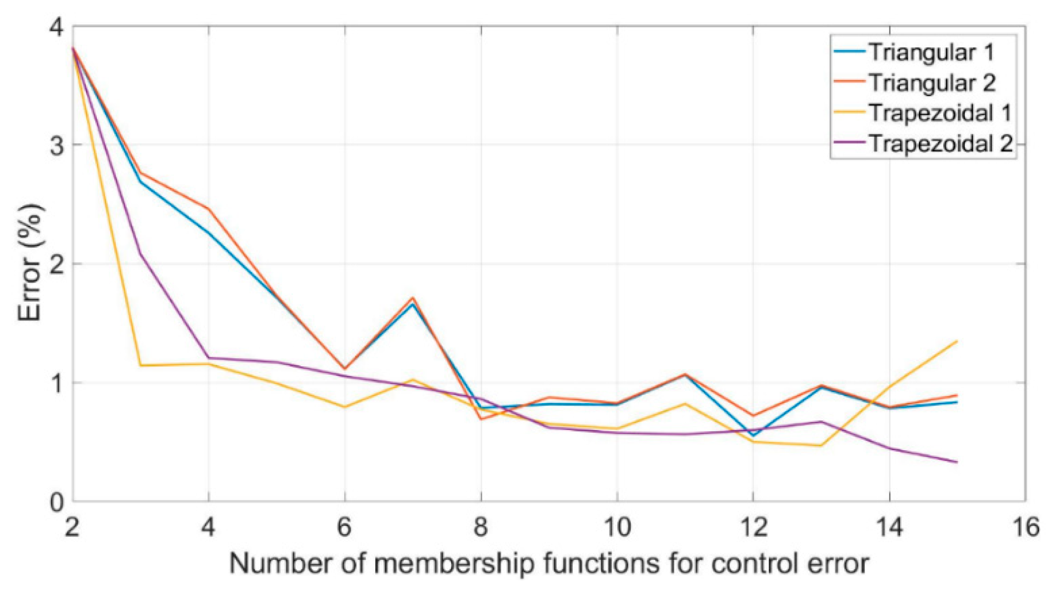
Figure 1. Utilization of the emergency mechanical ventilator BreaThU.
Actuators 10 00051 g001
Figure 2. Mechanical ventilator BreaThU.
Actuators 10 00051 g002
Figure 3. Pneumatic scheme of mechanical ventilator BreaThU.
Actuators 10 00051 g003
Figure 4. Control system of the mechanical ventilator BreaThU.
Actuators 10 00051 g004
Figure 5. Electrical scheme of developed hardware.
Actuators 10 00051 g005
Figure 6. Rapid decrease of the pressure.
Actuators 10 00051 g006
Figure 7. Adaptive neuro-fuzzy inference system (ANFIS) architecture.
Actuators 10 00051 g007
Figure 8. Control error during breathing cycle.
Actuators 10 00051 g008
Figure 9. The results of the training process for different numbers of membership functions.
Actuators 10 00051 g009
Figure 10. Training process.
Actuators 10 00051 g010
Figure 11. Process of training, testing and checking.
Actuators 10 00051 g011
Figure 12. Influence of control error and speed error on final control output.
Actuators 10 00051 g012
Figure 13. Influence of control error and reference pressure on final control output.
Actuators 10 00051 g013
Figure 14. Influence of error speed and reference pressure on final control output.
Actuators 10 00051 g014
Figure 15. Membership functions of control error, speed error and reference pressure. Top: initial membership functions. Bottom: membership functions after training process.
Actuators 10 00051 g015
Figure 16. Simplified model of AmbuBag. Individual images are as follows. Top left: real AmbuBag before compression, Bottom left: real AmbuBag after compression. Top right: Simplified model of AmbuBag before compression, Bottom right: Simplified model of AmbuBag after compression.
Actuators 10 00051 g016
Figure 17. Deformation of AmbuBag: (a) Change of AmbuBag shape, (b) auxiliary areas.
Actuators 10 00051 g017
Figure 18. Residual volume in AmbuBag with changing extension of the pneumatic actuator.
Actuators 10 00051 g018
Figure 19. Relation between opening of regulator EP.2 and output pressure.
Actuators 10 00051 g019
Figure 20. Relation between force compressing AmbuBag and its output pressure.
Actuators 10 00051 g020
Figure 21. Simulation model of mechanical ventilation for RPT mode.
Actuators 10 00051 g021
Figure 22. Simulation results. Top left: reference pressure 17 cmH2O, inspiration time ti = 0.42 s, expiration time te = 1.675 s. Top right: reference pressure 22 cmH2O, inspiration time ti = 0.6 s, expiration time te = 1.395 s. Bottom left: reference pressure 28 cmH2O, inspiration time ti = 1.215 s, expiration time te = 1.48 s. Bottom right: reference pressure 31 cmH2O, inspiration time ti = 1 s, expiration time te = 1.495 s.
Actuators 10 00051 g022
Figure 23. Experimental results from pressure control of mechanical ventilation. Top left: reference pressure 17 cmH2O. Top right: reference pressure 20 cmH2O. Bottom left: reference pressure 25 cmH2O. Bottom right: reference pressure 27 cmH2O.
Actuators 10 00051 g023
Figure 24. Experimental results of assisted breathing mode (ABM) ventilation.
Actuators 10 00051 g024
Table 1. Results from the training process—set 1.
Control Error (Number of MF)Speed Error (Number of MF)Reference. Pressure (Number of MF)Triangular (%)Trapezoidal (%)
2223.8213.813
3322.6861.142
4422.2571.154
5521.7130.992
6621.1160.793
7721.6581.022
8820.7850.772
9920.8180.651
101020.8130.61
111121.0630.82
121220.5510.5
131320.9570.469
141420.7820.962
151520.8341.35
Table 2. Results from the training process—set 2.
Control Error (Number of MF)Speed Error (Number of MF)Reference Pressure (Number of MF)Triangular (%)Trapezoidal (%)
2223.8213.813
3222.7632.078
4222.4591.206
5321.7281.17
6321.1111.052
7421.7130.968
8420.6890.861
9520.8740.619
10520.8250.575
11621.0680.564
12620.720.599
13720.9750.669
14720.7920.444
15820.8920.329
Publisher’s Note: MDPI stays neutral with regard to jurisdictional claims in published maps and institutional affiliations.

