
Active Loading Control Design for a Wearable Exoskeleton with a Bowden Cable for Transmission
by
 ,
,
Zhipeng Wang
1, 
Seungmin Rho
2,
Chifu Yang
1,
Feng Jiang
3,*,
Zhen Ding
1,
Chunzhi Yi
1 and
Baichun Wei
3 1
School of Mechatronics Engineering, Harbin Institute of Technology, Harbin 150001, China
2
Department of Industrial Security, Chung-Ang University, Seoul 06900, Korea
3
School of Computer Science and Technology, Harbin Institute of Technology, Harbin 150001, China
*
Author to whom correspondence should be addressed.
Actuators 2021, 10(6), 108; https://0-doi-org.brum.beds.ac.uk/10.3390/act10060108
Submission received: 26 April 2021
/
Revised: 19 May 2021
/
Accepted: 20 May 2021
/
Published: 24 May 2021
(This article belongs to the Special Issue High-Performance Compliant Robots and Soft Robots)
Abstract
:Exoskeletons with a Bowden cable for power transmission have the advantages of a concentrated mass and flexible movement. However, their integrated motor is disturbed by the Bowden cable’s friction, which limits the performance of the force loading response. In this paper, we solve this problem by designing an outer-loop feedforward-feedback proportion-differentiation controller based on an inner loop disturbance observer. Firstly, the inner loop’s dynamic performance is equivalent to the designed nominal model using the proposed disturbance observer, which effectively compensates for the parameter perturbation and friction disturbance. Secondly, based on an analysis of the stability of the inner loop controller, we obtain the stability condition and discuss the influence of modeling errors on the inner loop’s dynamic performance. Thirdly, to avoid excessive noise from the force sensors being introduced into the designed disturbance observer, we propose the feedforward-feedback proportion-differentiation controller based on the nominal model and pole configuration, which improves the outer loop’s force loading performance. Experiments are conducted, which verify the effectiveness of the proposed methods.
1. Introduction
Lower-limb exoskeletons can be divided into three types, according to their different auxiliary tasks. The first one enhances human strength and endurance [1,2]. The second focuses on assisting patients or elderly people with a partial decline in their motion performance [3,4]. The third is an exoskeleton [5,6] that is suitable for the rehabilitation training of patients with a near-loss walking ability. To reduce the impact of heavy loads on humans, weight-bearing is usually transferred to the ground [2]. The body balance of patients also needs to be supported by the rehabilitation of their exoskeleton [5]. The structures of these exoskeletons are usually rigid and run parallel to the limbs. Traditional rigid exoskeletons facilitate sensor integration and installation, and a dynamic model of these exoskeletons [7,8] has been established to realize zero-moment. However, for people with a normal motion capacity, the flexibility and comfort of rigid exoskeletons are still limited.
A wearable soft exosuit has been proposed [9], in which a Bowden cable is used for transmission. A Bowden cable can transmit displacement through the relative movement of an internal cable relative to an external sheath, which has the advantages of a flexible layout and long-distance transmission. Therefore, a wearable soft exosuit significantly enhances movement flexibility. Some studies have also applied a Bowden cable to the upper limb [10,11] and hands [12,13]. However, friction is produced during transmission through the Bowden cable. Moreover, the friction force of the Bowden cable is accompanied by hysteresis. Previous studies have focused on the influence of the mechanism design on human motion, most of which adopt a servo motor with a high power and high response [14,15]. The system has powerful off-board motors [15], which can overcome the Bowden cable’s disturbance using a simple controller, such as PID, and complete force loading efficiently. However, due to its large size and mass, the motor can only be placed off-board. This is not conducive to improving the exoskeleton’s modularity and practicability. A low-power motor can be integrated into the exoskeleton. However, the motor’s time-varying parameters and anti-interference ability are insufficient under a large load and friction interference. An exciting high torque density actuation [16] has been proposed to reduce the quality of the motor, which is beneficial for the integration of the exoskeleton. The dynamic performance of force loading was verified by a squatting experiment. The cycle of squatting was 8s, and the speed of the Bowden cable was slower. The experiment [17] shows that a smaller cable moving speed and stiffer cable/sheath can increase the force transmission efficiency. More than half of the motor torque is used to overcome the Bowden cable’s friction [18] when the speed increases. Therefore, in the process of walking, the disturbance of Bowden cable friction needs to be further considered.
Some researchers regard the friction of the Bowden cable as disturbance. Christopher [12] proposes position feedback control to suppress the Bowden cable’s interference with the position accuracy. The backlash hysteresis parameters are estimated online [19] and compensated for by an adaptive position controller to solve backlash hysteresis in a surgical robot. The target of position control is displacement, rather than interaction, so it is more suitable for rehabilitation training. The iterative force-based position control method [20] can realize force loading based on compensating for active human motion. The position closed loop is adopted in the inner loop, which can suppress the Bowden cable’s friction to a certain extent. The motor consists of a current loop, speed loop, and position loop, the dynamic response of which decreases gradually [21]. Therefore, the iterative force-based velocity control method [22] was proposed to improve the inner loop’s response speed. However, closed-loop control can only suppress the friction interference to a certain and cannot wholly compensate for the interference of the friction with the closed-loop performance.
A large number of studies focus on the friction characteristics. The Bowden cable’s friction is affected by many factors [23,24,25,26], such as the diameter, material, bending angle, cable speed, etc. Kuan et al. [27] proposed a cable-drive module with rolling cable transmissions based on the structural design. However, the flexibility of the Bowden cable is reduced. Lawrence et al. [28] designed a friction model for the coefficient of friction and wrapping angle. Jeong et al. [29,30] believe that the bending angle mainly determines the Bowden cable’s friction. The method of using an angle sensor to estimate the Bowden cable’s bending angle is proposed. Then, the friction model is established for feedforward compensation. The experimental results prove the method’s effectiveness, which is suitable for occasions where the experimental bench is fixed. Adding an angle sensor to each Bowden cable will increase the number of controller acquisition channels. The exoskeleton needs to be highly integrated, and for safety, the fewer sensors, the better.
The study has still been paid little attention due to the limited number of sensors. The anti-interference ability of the integrated motor in the exoskeleton is weak. Moreover, the force loading frequency range needs to be further widened to enhance the assistant. Therefore, an algorithm needs to be proposed. The change in the inner loop’s dynamic performance directly affects the outer loop’s rapidity and stability. It is difficult to obtain a satisfactory dynamic performance by designing an outer-loop controller. It is exciting that the disturbance observer (DOB) [31,32] can observe external disturbance and parameter perturbation. Therefore, the DOB in the inner loop can not only reduce the number of sensors, but also compensate for the Bowden cable’s friction. Most outer-loop controllers need to be designed based on force error signals, such as PID and other advanced algorithms [33]. The sliding mode controller [33] can be designed based on a nominal model of the inner loop. However, to overcome the nonlinear and unknown disturbance, the sliding-mode control will produce high-frequency chattering. When the inner loop adopts the DOB, designing the controller based on the force error signal can introduce noise from the force sensor into the inner loop. Therefore, a feedforward-feedback proportion-differentiation controller (FFPD) based on a nominal model is proposed in this paper.
The main contribution of this paper is the design of an active loading control strategy, with a Bowden cable for transmission. Firstly, the control framework of the outer force loop based on the inner velocity loop is established. To improve the anti-interference ability of the inner loop, this paper proposes a DOB. The inner loop is equivalent to the designed nominal model, which effectively compensates for the parameter perturbation of the inner loop and the friction disturbance caused by the Bowden cable. The influence of modeling errors, with an increasing frequency, on the inner loop’s dynamic performance is further discussed. Moreover, the stability condition of the inner loop is obtained. On this basis, the FFPD is proposed, which can avoid excessive force sensor noise being introduced into the inner loop and improve the force loading performance of the outer loop through pole configuration.
2. Mathematical Modeling of the System
A Bowden cable can transmit displacement through the relative movement of an internal cable relative to an external sheath, which has the advantages of a flexible layout and long-distance transmission. Therefore, a wearable exoskeleton with a Bowden cable for transmission is introduced in this paper. A power supply, motors, controllers, and other components are integrated near the body’s center of gravity. The power is transmitted to the lower limb fixation mechanism of the knee joint through the Bowden cable.
The fixation mechanism of the knee joint is shown in Figure 1. The cable sheath is connected to the motor base and the support module. Moreover, the inner cable is connected to the motor output shaft and the knee joint sheave. Two lightweight carbon fiberboards (LCFB) form a rotating joint, and the hinge mechanism forms a rotating joint on the coronal plane of the knee joint. The baffles are connected to the thigh and calve with a few flexible straps. Since the assistance needs to be performed based on the human body’s active movement, an encoder at the knee joint is installed. Moreover, a force loading control framework based on a speed loop is proposed.
However, friction will be produced during transmission through the Bowden cable. More than half of the motor torque is used to overcome the Bowden cable’s friction [27]. In the process of human movement, the Bowden cable’s angle changes with the swing of the thigh. The friction between the cable sheath and the inner cable will also change constantly. These factors all increase the difficulty of friction modeling. On the other hand, due to the small power of the integrated motor, the anti-interference ability is insufficient. Under the interference of the Bowden cable’s friction, the parameter perturbation of the motor will be increased, which will further deteriorate its dynamic performance. Therefore, due to the limited number of sensors and the actuator’s poor anti-interference ability, the controller design should be used to improve the dynamic performance of force loading.
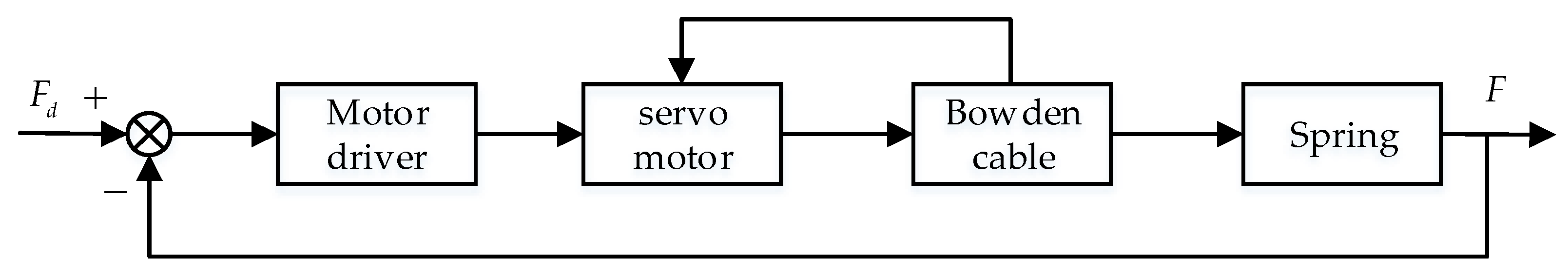
This article pays more attention to solving the following problems: compensating for the Bowden cable’s friction and improving the dynamic performance of force loading. Therefore, the exoskeleton and human movement are not involved in this paper. The end of the inner cable is connected to the fixed base. The entire system can be regarded as active force loading, with a Bowden cable for transmission. The system’s mathematical model only considers the driver, integrated servo motor, Bowden cable, spring, and force sensor, as shown in Figure 2. is the force command. is the force response.
The closed-loop transfer function of the velocity loop is:
where is the moment of inertia equivalent to the motor shaft, is the inductance coefficient, is the current feedback coefficient, is the resistance coefficient, is the amplification factor of the velocity loop, is the amplification factor, is the motor back EMF coefficient, is the equivalent viscous damping, is the torque coefficient, and is the feedback coefficient of the velocity loop.
The moment balance equation is:
where is the output torque of the current loop, is the equivalent torque from the interaction force to the motor shaft, is the equivalent torque from the Bowden cable friction to the motor shaft, is a Laplacian operator, is the angular velocity of the motor shaft, is the reduction ratio, is the interaction force, and is the radius of the motor sheave.
Combined with Equations (1)–(4), the block diagram of the inner loop can be obtained, as shown in Figure 3. is the spring stiffness, and is a function of the Bowden cable’s friction. It can be seen, from Figure 3, that the block diagram of the inner loop is composed of a servo motor current loop, speed loop, and mechanism expression. When the motor is set as the current loop, friction torque disturbance is not included in the current loop. Therefore, it can only be compensated for by the Bowden cable friction model. When the motor is set as the velocity loop, the disturbance caused by friction torque is included. On the one hand, the velocity loop can decrease the disturbance. On the other hand, the disturbance can be compensated for by the DOB. Moreover, the number of sensors can be reduced.
3. Controller Design
3.1. Design of the Inner-Loop Controller
In a gait cycle, there is only one peak in the unidirectional assist curves of the hip and ankle joints. The force command can be set to 0 during the rest of a gait cycle. There are three peaks in the flexion direction of the knee joint. Moreover, the knee’s maximum flexion angular velocity is twice that of the hip joint and ankle joint. Since the inner loop needs to overcome the interference of the friction and interaction force, the output power is enormous. The internal parameters of the motor have a certain nonlinearity and time variance. In this case, it is not ideal to enhance the dynamic response using the feedforward model. Generally, although the inner loop’s nominal model is not the same as the actual model, the transfer function is of the same type. Therefore, the inner loop’s nominal model can be expressed as follows:
The physical meaning of each nominal parameter in Equation (5) is the same as that of each nominal parameter in Equation (1). The DOB can be designed as follows:
where is the equivalent disturbance expressed by the DOB, is the velocity error, and is the equivalent disturbance caused by and , the formula of which is:
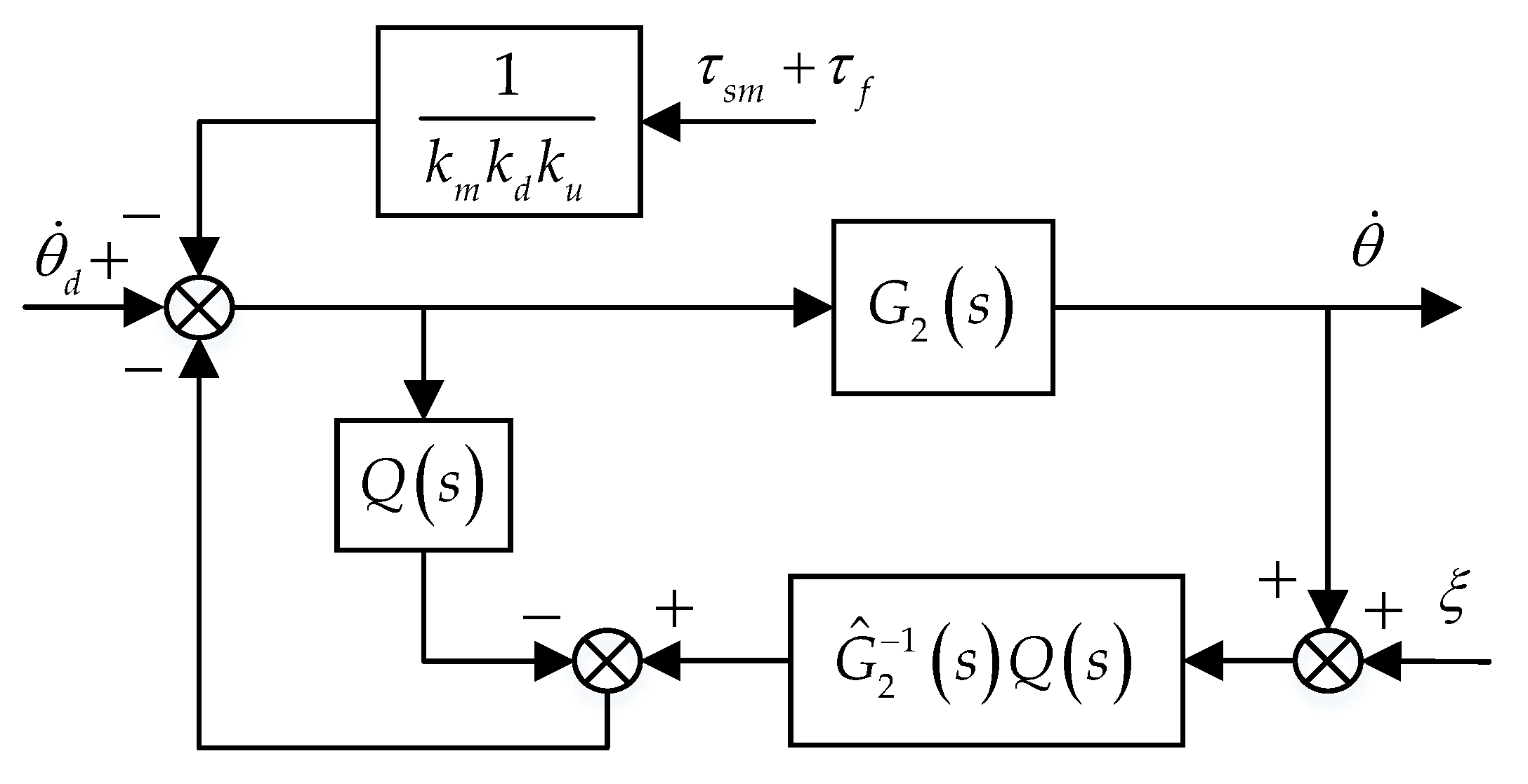
Combining Equations (5)–(7), the control block diagram of the inner loop based on the DOB can be simplified, as shown in Figure 4.
In Figure 4, is the high-frequency noise of the speed signal. is a low-pass filter. The requirement of keeping regularization should be satisfied. As shown in Figure 4, can be amplified by , which will affect the stability of the system. Therefore, it is necessary to design a low-pass filter . According to Figure 4, the transfer functions are as follows:
The error between the nominal and the actual models is small in the low-frequency range, as shown in Equation (11)
In the assistance process, the inner loop needs to overcome the friction disturbance torque and interactive torque. Therefore, the actual model of the inner loop has parameter perturbation. Combining Figure 4 and Equation (8), Equation (12) can be obtained as follows:
where is the perturbation of the actual model relative to the nominal model in the presence of disturbance. Combining Equations (8), (11) and (12), the sensitivity function can be obtained as follows:
Then, the complementary sensitivity function can be written as:
According to the robust stability theorem, the stability condition of the inner loop can be obtained as follows:
The sinusoidal sweep signal, with an amplitude of 45 r/min and frequency of 1–7 Hz, is adopted as the speed command of the inner loop. The tracking curve in the 3–7 Hz frequency band of the sweep signal is intercepted to observe the tracking effect more clearly. The dynamic response curve of the inner loop without a load is shown in Figure 5. It can be seen, from Figure 5, that the amplitude of the inner loop has almost no attenuation. Only the phase lags by 15 ms.
In the low-frequency band, . Substituting it into Equations (8)–(10), the results are as follows:
According to Equation (16), the design of the filter should include the ability to suppress disturbance and noise sensitivity. In the low-frequency band, the motor’s response is consistent with the nominal model established in this paper. The DOB can effectively compensate for the friction disturbance torque and interaction torque. Moreover, the high-frequency noise has little effect on the output of the motor. In the high-frequency band, . Substituting it into Equations (8)–(10), the results are as follows:
In the high-frequency band, the motor performance shows its actual dynamic response. The influence of friction torque and interaction torque cannot be suppressed. High-frequency noise has little effect on the output speed. Since human motion is in the low-frequency band, the dynamic response of the velocity loop in the high-frequency range can be ignored. Therefore, within the bandwidth of , the torque disturbance, the modeling perturbance between the actual system and the nominal model will be compensated for. The dynamic performance of the inner loop can be regarded as . Combined with Equations (8), (16) and (17), Equation (18) can be rewritten as:
According to Equations (15) and (18), the inner loop’s anti-interference ability is enhanced in the low-frequency band. The conditions for improving the stability of the inner loop are obtained considering the modeling error. The accuracy of the nominal model should be improved as much as possible, on the one hand, to ensure the inner loop’s stability, and on the other, to reduce the operating range of the inner loop in order to minimize the perturbation. Under the premise of the inner loop stability, the broader the bandwidth of the filter is, the stronger the anti-interference ability in the low-frequency band is. Consequently, the potential force loading performance can be further enhanced.
3.2. Design of the Oute-Loop Controller
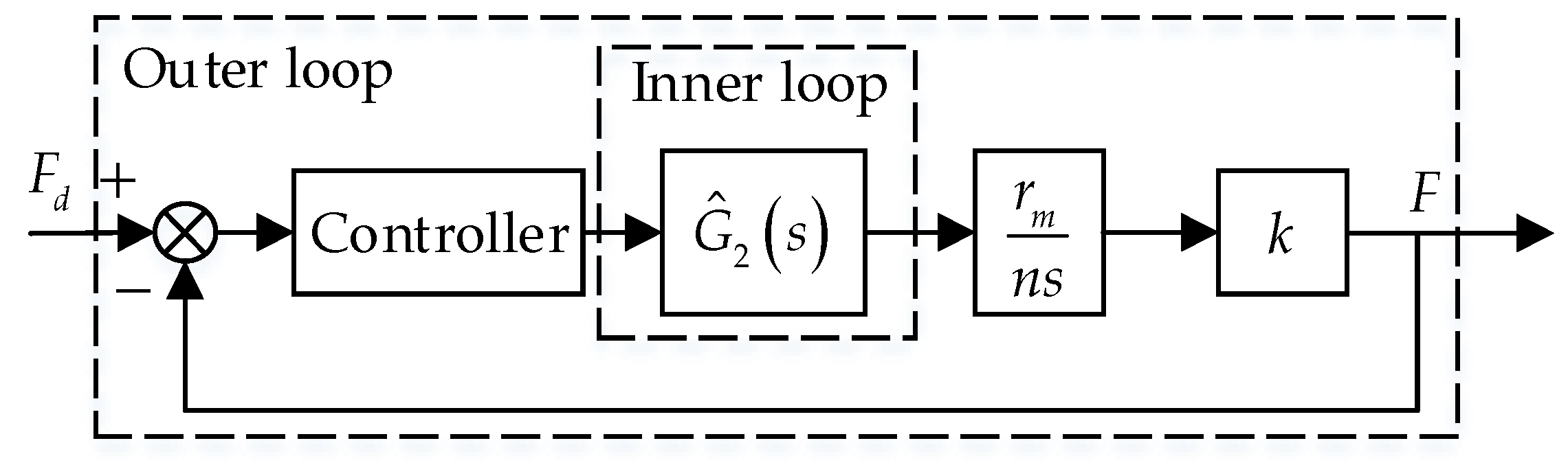
The block diagram of the outer loop is shown in Figure 6. is the force command, and is the force response.
According to Equation (18), the dynamic performance of the inner loop in the low-frequency band is consistent with the nominal model. In other words, the DOB control method proposed in the inner loop can effectively compensate for not only the interference of friction with the inner loop, but also the nonlinearity and modeling errors caused by the parameter perturbation. Therefore, the outer-loop controller can also be designed based on , which can effectively avoid the model parameter perturbation and nonlinearity of the inner loop.
In the low-frequency band, combined with Equations (5), (18) and Figure 6, the outer loop model is shown in the following:
where
The force error of the outer loop can be expressed as:
By substituting Equation (21) into Equation (19) and combining it with the PD control, the control rate can be obtained as:
The equation of the force error can be obtained by substituting Equation (22) into Equation (22):
Using the Laplace transform, Equation (23) can be rewritten as:
Equation (24) is a characteristic equation concerning force error. The solution of Equation (24) can represent the rapidity and stability of the outer loop. The dynamic performance in the outer loop can be changed by adjusting and . To ensure that the eigenvalues are located on the left side of the virtual axis, the desired characteristic equation can be written as:
The coefficients of Equations (24) and (25) are made to be equal, that is:
where , , and are the expected poles. Hence, and can be obtained according to the expected , , and .
4. Results
4.1. Test Setup
As a preliminary detection, the corresponding force loading control strategy, with a Bowden cable for transmission, is proposed. The scheme process is shown in Figure 7, including the control system, mechanical structure, and sensors.
The control system is a single task mode, which includes a host computer and a target computer. The PC can be used as a host computer, and the LabVIEW software can be run on it. The control program can be built and compiled in the LabVIEW software. Then, the compiled program can be deployed to the target computer through a shared local area network (LAN). An industrial computer can be used as the target computer. The target computer has a high-speed real-time computing environment, which can collect data and send control signals through the program deployed therein. To improve the integration, the Sbrio-9636 is selected as the target computer. The vendor of the servo motor is the Hai Tai Electromechanical Equipment in YiWu, China. The model used in this paper is the HT-02. The servo motor integrates a 6:1 reduction ratio, and the total weight is 480 g. The rated torque and rated speed after the reducer are 7.6 Nm and 250 RPM, respectively. The mechanical structure is composed of the servo motor, Bowden cable, spring, and three L-shaped supports. The motor and three L-shaped supports are fixed on a steel plate. The cable sheath is connected to a 1# L-shaped support and 2# L-shaped support. The inner cable is connected to the motor output shaft and the spring. The inner cable and the cable sheath move relative to each other and are driven by the servo motor.
The torque curve in the knee joint’s flexion direction has three peaks, and its frequency gradually increases. The curve selected in this paper can basically cover the force loading frequency range of human motion. Therefore, the average force curve of the knee joint flexion direction is obtained by the Vicon system when the human body is walking at 4.5 km/h. To verify the effectiveness of the method proposed in this paper, the dynamic performance of the system using the different control methods is comprehensively compared through experiments. Firstly, both the inner loop and outer loop adopt PID control to verify the necessity of the control method proposed in this article. Secondly, the experimental results in Section 4.2 and Section 4.3 were compared to further verify the influence of the inner loop performance on the outer loop. Finally, springs with different stiffnesses are used to verify the influence of model errors on the dynamic performance of the system.
Because of the high flexibility, the inner cable may not be tensioned before the experiment. Therefore, at the beginning of the experiment, the motor rotates at the speed of 0.2 r/min until the force sensor value is greater than 5 N.
4.2. Friction Verification of the Bowden Cable
In this section, the tension relationship of the inner cable at the 1# and 3# L-shaped supports is used to verify the hysteresis phenomenon of the Bowden cable’s friction. The proportional control is adopted, and the force response curve is shown in Figure 8. and are the force of the inner cable at the 1# and 3# L-shaped supports, respectively. It can be seen, from Figure 8, that 43% of is used to overcome the Bowden cable’s friction. It also can be seen, from Figure 9, that the friction of the Bowden cable has a strong hysteresis. Therefore, the Bowden cable’s friction cannot be ignored or simply suppressed by closed-loop control during the force loading.
4.3. PID Control in Both the Inner and Outer Loop
Firstly, PID control is adopted in both the inner loop and outer loop, the responses of which are shown in Figure 10, Figure 11 and Figure 12. As shown in Figure 10, the phase lag from 0 s to 0.4 s is about 0.1 s, and there is almost no amplitude attenuation. However, within 0.8–1.1 s, the frequency of the force curve increases. The force response is almost constant during the rapid change in the force command, indicating that the dynamic performance of the outer loop is poor. Figure 12 shows the integral curve of the velocity response. Moreover, the force response of Figure 10 is scaled to the same order of magnitude as the integral curve of the velocity response. As shown in Figure 12, is the force response curve after scaling. It can be seen that the displacement response of the Bowden cable close to the motor is significantly earlier than the force response, which shows that the friction hinders the Bowden cable’s transmission. It can also be seen, from Figure 12, that when the loading force is small, the flexible connection between the Bowden cable and the spring has a more significant impact on the force loading. Therefore, it is difficult for PID control to meet the force loading performance.
4.4. The FFPD in the Outer Loop
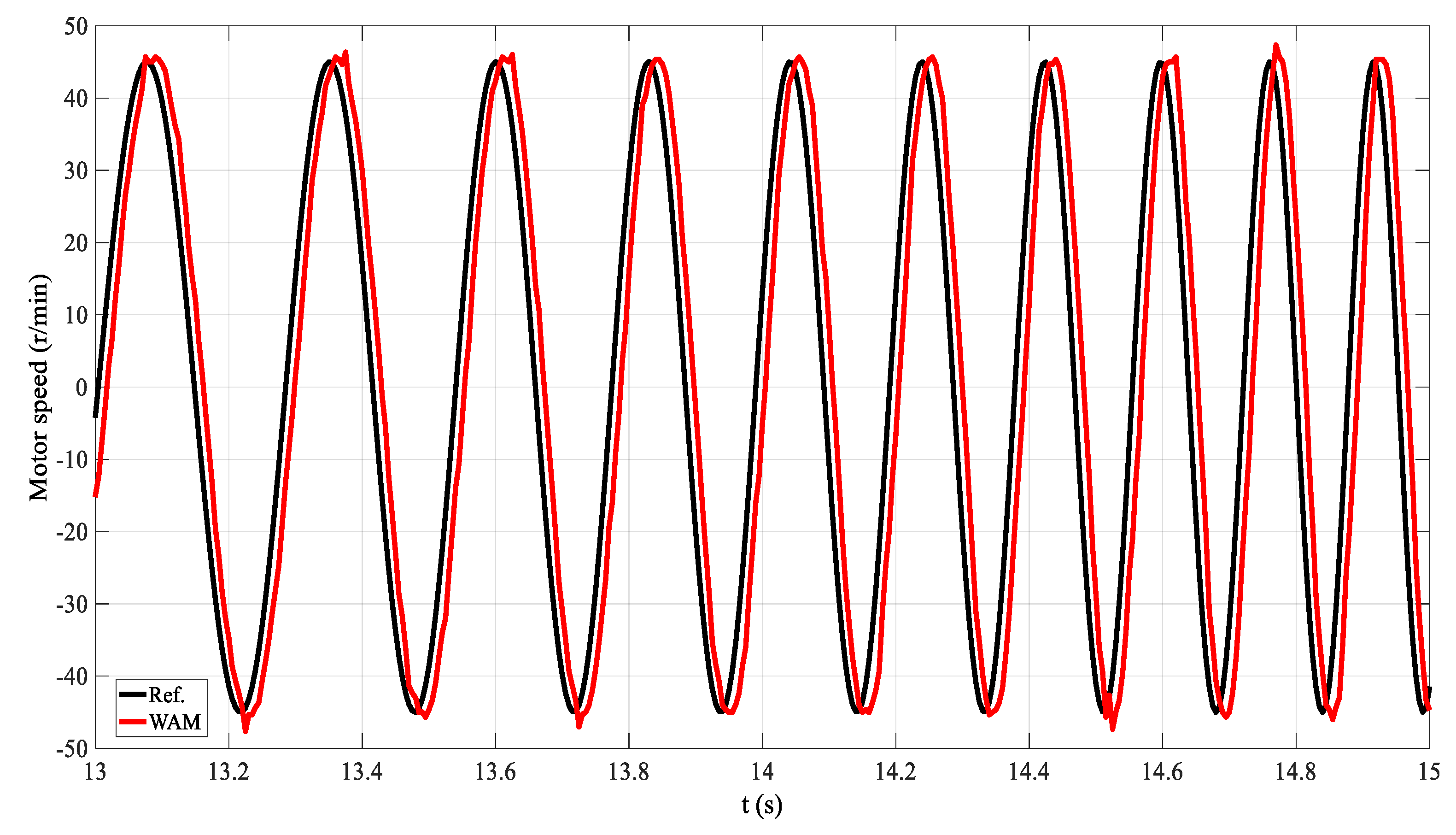
The sinusoidal sweep signal, with an amplitude of 45 r/min and frequency of 1–7 Hz, is adopted as the speed command in the inner loop. The tracking curve in the 3–7 Hz range is intercepted to observe the tracking effect more clearly. The identified model without a load is as follows:
The dynamic response of the nominal model (NM) and actual model without a load (WAM) is shown in Figure 13. The nominal model shown in Equation (27) reduces the time delay by 5 ms, compared to that of the actual model. The dynamic performance of the nominal model is basically consistent with that of the actual model. Therefore, the feedforward compensation and the DOB can be designed based on Equation (27).
The FFPD is adopted to further verify the influence of the inner loop performance on the outer loop. According to Equation (27), the dynamic responses under the FFPD are obtained, as shown in Figure 14, Figure 15 and Figure 16. In Figure 14, the phase lag from 0–0.4 s is about 0.06 s, which reduces the time delay by 40%, compared with that of PD control. Therefore, it can be proved that the phase lag can be compensated for by the feedforward control. From 0.8–1.1 s, the tracking performance of the first peak is greatly improved, compared with PD control. Moreover, the phase of the first peak is advanced by 25%. However, the tracking performance of the second peak is poor. The dynamic response of the inner loop becomes worse in Figure 15, which further limits the improvement of the dynamic performance in the outer loop. Therefore, it is necessary to compensate for the Bowden cable’s friction and improve the inner loop’s anti-interference ability. As shown in both Figure 12 and Figure 16, the interaction force does not change proportionally with the displacement change. This also proves the phenomenon of friction hysteresis.
Feedforward control can improve the dynamic performance of force loading to a certain extent. However, due to the limitation of the inner loop, the force loading performance still cannot be further improved.
4.5. The FFPD in the Outer Loop and the DOB in the Inner Loop
The following conclusions are obtained through theoretical analysis. The enhancement of the dynamic performance in the inner loop can further improve the dynamic response in the outer loop. Moreover, the stability of the inner loop depends on the perturbation of the actual model, according to Equation (15). With the increase of the frequency, the inner loop’s perturbation is stronger, and the anti-interference ability becomes worse. To verify the correctness of the above analysis, the spring stiffness is increased and compared with the dynamic performance of . The values of the spring stiffnesses and are and , respectively. The dynamic response is shown in Figure 17, Figure 18 and Figure 19, when the outer-loop FFPD controller, based on an inner-loop DOB, is adopted.
According to Figure 17, the phase lag of the force curve is about 0.07 s in 0–0.4 s, which reduces the time delay by 30%, compared with that of PD control. The response amplitude of the second peak increases from 7 N to 80 N and 66 N, respectively. Compared with the feedforward controller, the resulting amplitude is much improved. Comparing Figure 15 with Figure 18, the command amplitude and frequency of the inner loop have both increased. This shows that the DOB controller can not only effectively compensate for the Bowden cable’s friction, but also effectively enhance the anti-interference ability in the inner loop. Moreover, the dynamic performance is approximately the nominal model. Designing the feedforward control in the outer loop based on the nominal model is also more conducive to improving the force loading performance.
The force response curve under has an overshoot of 8 N at 1.2 s. Correspondingly, the force response curve under has no overshoot. Besides, the force response curve with is ahead of that with in phase. It can also be verified, from Figure 18 and Figure 19, that when the stiffness is , the bandwidth required by the inner loop increases. Therefore, it is verified that the larger the model error, the worse the system stability.
The experimental results show that the higher the spring stiffness, the better the force loading response. Comparing Figure 14 and Figure 17, it can be concluded that only by improving the inner loop’s dynamic response can the outer loop’s dynamic performance be further improved. While there is still a phase lag of 0.06 s, the number of sensors required is reduced. Based on the above analysis, the inner loop adopts the DOB, and the outer loop adopts the FFPD, which can meet the force loading performance of the knee joint.
5. Conclusions
In this paper, an outer-loop FFPD controller with a DOB in the inner loop is proposed. Besides, the force loading performance with the Bowden cable for transmission is effectively improved by the controller designed in this paper. The experimental results show that the FFPD can increase the phase by 40%, compared with the traditional PD control. The response amplitude of the first peak increases from 7 N to 38 N. However, the second peak is only 14 N. The inner loop DOB can effectively compensate for the parameter perturbation and friction disturbance. The designed nominal model is more suitable for the designing the FFPD. The experimental results show that the second peak’s response amplitude increases from 7 N to 66 N using the proposed DOB. While there is still a phase lag of 0.06 s, the number of sensors required is reduced. It is verified that the larger the model error, the worse the system stability. The inner loop’s stability condition increases the spring stiffness by improving the modelling accuracy as much as possible. Taking two spring stiffnesses as an example, the outer loop’s tracking curve with has an overshoot of 8 N at 1.2 s. Correspondingly, the outer loop’s tracking curve with is not only ahead of that with in phase, but also has no overshoot. The method proposed in this paper can be applied not only to force loading with a Bowden cable for power transmission, but also to other force loading systems.
Author Contributions
Conceptualization, Z.W.; methodology, Z.W.; software, Z.W.; validation, Z.W., S.R., Z.D. and C.Y. (Chunzhi Yi); formal analysis, Z.W.; investigation, Z.W.; resources, Z.W.; data curation, Z.W. and B.W.; writing—original draft preparation, Z.W.; writing—review and editing, Z.W., S.R., C.Y. (Chifu Yang) and F.J.; visualization, Z.W., S.R., C.Y. (Chifu Yang) and Z.D.; supervision, F.J.; project administration, F.J. and C.Y. (Chifu Yang); funding acquisition, F.J. All authors have read and agreed to the published version of the manuscript.
Funding
This work is partly funded by National Key Research and Development Program of China (No.2018YFC0832105) and National Natural Science Foundation of China (No. 61872112).
Institutional Review Board Statement
Not applicable.
Informed Consent Statement
Not applicable.
Data Availability Statement
Data sharing not applicable.
Acknowledgments
The authors express their gratitude to the National Key Research and Development Program of China for project funding.
Conflicts of Interest
The authors declare no conflict of interest.
Abbreviations
The following abbreviations are used in this manuscript:
| FFPD | Feedforward-feedback PD controller |
| DOB | Disturbance observer |
References
- Choi, B.; Seo, C.; Lee, S.; Kim, B. Control of power-augmenting lower extremity exoskeleton while walking with heavy payload. Int. J. Adv. Robot. Syst. 2019, 16, 1–16. [Google Scholar] [CrossRef] [Green Version]
- Song, G.K.; Huang, R.; Qiu, J.; Cheng, H.; Fan, S. Model-based Control with Interaction Predicting for Human-coupled Lower Exoskeleton Systems. J. Intell. Robot. Syst. 2020, 100, 389–400. [Google Scholar] [CrossRef]
- Sulzer, J.S.; Roiz, R.A.; Peshkin, M.A.; Patton, J.L. A highly backdrivable, lightweight knee actuator for investigating gait in stroke. IEEE Trans. Robot. 2009, 25, 539–548. [Google Scholar] [CrossRef] [PubMed]
- Dawson-Elli, A.R.; Adamczyk, P.G. Design and Validation of a Lower-Limb Haptic Rehabilitation Robot. IEEE Trans. Neural Syst. Rehabil. Eng. 2020, 28, 1584–1594. [Google Scholar] [CrossRef] [PubMed]
- Lippi, V.; Mergner, T. A Challenge: Support of Standing Balance in Assistive Robotic Devices. Appl. Sci. 2020, 10, 5240. [Google Scholar] [CrossRef]
- Wu, Y.N.; Hwang, M.; Ren, Y.; Gaebler-Spira, D.; Zhang, L.Q. Combined passive stretching and active movement rehabilitation of lower-limb impairments in children with cerebral palsy using a portable robot. Neurorehabilit. Neural Repair. 2011, 25, 378–385. [Google Scholar] [CrossRef]
- Zhang, T.; Tran, M.; Huang, H. Admittance shaping-based assistive control of SEA-driven robotic hip exoskeleton. IEEE/ASME Trans. Mechatron. 2019, 24, 1508–1519. [Google Scholar] [CrossRef]
- Huo, W.G.; Mohammed, S.; Amirat, Y. Impedance reduction control of a knee joint human-exoskeleton system. IEEE Trans. Control Syst. Technol. 2019, 27, 2541–2556. [Google Scholar] [CrossRef]
- Asbeck, A.T.; De Rossi, S.M.; Galiana, I.; Ding, Y.; Walsh, C.J. Stronger, Smarter, Softer: Next-Generation Wearable Robots. IEEE Robot. Autom. Mag. 2014, 21, 22–33. [Google Scholar] [CrossRef]
- Wu, Q.C.; Wang, X.S.; Chen, B.; Wu, H.G. Development of an RBFN-based neural-fuzzy adaptive control strategy for an upper limb rehabilitation exoskeleton. Mechatronics 2018, 53, 85–94. [Google Scholar] [CrossRef]
- Xiloyannis, M.; Annese, E.; Canesi, M.; Kodiyan, A.; Bicchi, A.; Micera, S.; Ajoudani, A.; Masia, L. Design and Validation of a Modular One-To-Many Actuator for a Soft Wearable Exosuit. Front. Neurorobot. 2019, 13, 39. [Google Scholar] [CrossRef]
- Nycz, C.J.; Butzer, T.; Lambercy, O.; Arata, J.; Fischer, G.S.; Gassert, R. Design and Characterization of a Lightweight and Fully Portable Remote Actuation System for Use with a Hand Exoskeleton. IEEE Robot. Autom. Lett. 2016, 1, 976–983. [Google Scholar] [CrossRef]
- Zhang, F.H.; Hua, L.; Fu, Y.L.; Chen, H.W.; Wang, S.G. Design and development of a hand exoskeleton for rehabilitation of hand injuries. Mech. Mach. Theory 2016, 73, 103–116. [Google Scholar] [CrossRef]
- Pinto-Fernandez, D.; Torricelli, D.; Sanchez-Villamanan, M.D.; Aller, F.; Mombaur, K.; Conti, R.; Vitiello, N.; Moreno, J.C.; Pons, J.L. Performance Evaluation of Lower Limb Exoskeletons: A Systematic Review. IEEE Trans. Neural Syst. Rehabil. Eng. 2020, 28, 1573–1583. [Google Scholar] [CrossRef] [PubMed]
- Bryan, G.M.; Franks, P.W.; Klein, S.C.; Peuchen, R.J.; Collins, S.H. A hip–knee–ankle exoskeleton emulator for studying gait assistance. Int. J. Robot. Res. 2020, 40, 1–25. [Google Scholar] [CrossRef]
- Yu, S.Y.; Huang, T.H.; Wang, D.P.; Lynn, B.; Sayd, D.; Silivanov, V.; Park, Y.S.; Tian, Y.L.; Su, H. Design and Control of a High-Torque and Highly-Backdrivable Hybrid Soft Exoskeleton for Knee Injury Prevention during Squatting. IEEE Robot. Autom. Lett. 2019, 4, 4579–4586. [Google Scholar] [CrossRef]
- Chen, D.Y.; Yun, Y.; Deshpande, A.D. Experimental characterization of Bowden cable friction. In Proceedings of the 2014 IEEE International Conference on Robotics and Automation (ICRA), Hong Kong, China, 31 May–7 June 2014; pp. 5927–5933. [Google Scholar] [CrossRef]
- Li, J.T.; Zheng, R.Y.; Zhang, Y.R.; Yao, J.C. iHandRehab: An interactive hand exoskeleton for active and passive rehabilitation. In Proceedings of the 2011 IEEE International Conference on Rehabilitation Robotics (ICORR), Zurich, Switzerland, 27 June–1 July 2011; pp. 1–6. [Google Scholar] [CrossRef]
- Do, T.N.; Tjahjowidodo, T.; Lau, M.W.; Phee, S.J. Adaptive Control of Position Compensation for Cable-Conduit Mechanisms Used in Flexible Surgical Robots. In Proceedings of the 2014 11th International Conference on Informatics in Control, Automation and Robotics (ICINCO), Vienna, Austria, 1–3 September 2014; pp. 110–117. [Google Scholar] [CrossRef]
- Ding, Y.; Galiana, I.; Asbeck, A.; Quinlivan, B.; Rossi, S.M.; Walsh, C. Multi-joint actuation platform for lower extremity soft exosuits. In Proceedings of the 2014 IEEE International Conference on Robotics and Automation (ICRA), Hong Kong, China, 31 May–7 June 2014; pp. 1327–1334. [Google Scholar] [CrossRef]
- Li, P.; Zhu, G.L.; Zhang, M.M. Linear Active Disturbance Rejection Control for Servo Motor Systems with Input Delay via Internal Model Control Rules. IEEE Trans. Ind. Electron. 2021, 68, 1077–1086. [Google Scholar] [CrossRef]
- Lee, G.; Ding, Y.; Bujanda, I.G.; Karavas, N.; Zhou, Y.M.; Walsh, C.J. Improved assistive profile tracking of soft exosuits for walking and jogging with off-board actuation. In Proceedings of the 2017 IEEE/RSJ International Conference on Intelligent Robots and Systems (IROS), Vancouver, BC, Canada, 24–28 September 2017; pp. 1699–1706. [Google Scholar] [CrossRef]
- Kesner, S.B.; Howe, R.D. Position control of motion compensation cardiac catheters. IEEE Trans. Robot. 2011, 27, 1045–1055. [Google Scholar] [CrossRef] [Green Version]
- Palli, G.; Borghesan, G.; Melchiorri, C. Modeling, Identification, and Control of Tendon-Based Actuation Systems. IEEE Trans. Robot. 2012, 28, 277–290. [Google Scholar] [CrossRef]
- Jeong, U.; Cho, K.J. A novel low-cost, large curvature bend sensor based on a Bowden-cable. Sensors 2016, 16, 961. [Google Scholar] [CrossRef]
- Palli, G.; Melchiorri, C. Model and control of tendon-sheath transmission systems. In Proceedings of the 2006 IEEE International Conference on Robotics and Automation, Orlando, FL, USA, 15–19 May 2006; pp. 988–993. [Google Scholar] [CrossRef]
- Kuan, J.Y.; Pasch, K.A.; Herr, H.M. A High-Performance Cable-Drive Module for the Development of Wearable Devices. IEEE/ASME Trans. Mechatron. 2018, 23, 1238–1248. [Google Scholar] [CrossRef]
- Carlson, L.E.; Veatch, B.D.; Frey, D.D. Efficiency of Prosthetic Cable and Housing. JPO J. Prosthet. Orthot. 1995, 7, 96–99. [Google Scholar] [CrossRef]
- Jeong, U.; Cho, K.J. Control of a Bowden-Cable Actuation System with Embedded BoASensor for Soft Wearable Robots. IEEE Trans. Ind. Electron. 2019, 67, 7669–7680. [Google Scholar] [CrossRef]
- Jeong, U.; Cho, K. Feedforward friction compensation of Bowden-cable transmission via loop routing. In Proceedings of the 2015 IEEE/RSJ International Conference on Intelligent Robots and Systems (IROS), Hamburg, Germany, 28 September–2 October 2015; pp. 5948–5953. [Google Scholar] [CrossRef]
- Wang, W.J.; Yu, L.T.; Yang, J. Toward force detection of a cable-driven micromanipulator for a surgical robot based on disturbance observer. Mech. Sci. 2017, 8, 323–335. [Google Scholar] [CrossRef]
- Chen, W.H.; Yang, J.; Guo, L.; Li, S.H. Disturbance-Observer-Based Control and Related Methods—An Overview. IEEE Trans. Ind. Electron. 2016, 63, 1083–1095. [Google Scholar] [CrossRef] [Green Version]
- Zhao, J.S.; Wang, Z.P.; Yang, T.; Xu, J.X.; Ma, Z.L.; Wang, C.F. Design of a novel modal space sliding mode controller for electro-hydraulic driven multi-dimensional force loading parallel mechanism. ISA Trans. 2020, 99, 374–386. [Google Scholar] [CrossRef]
Figure 1.
The fixation mechanism of the knee joint.

Figure 2.
Simple block diagram of the system model.

Figure 3.
Block diagram of the inner loop.

Figure 4.
Block diagram of the inner loop based on the DOB.

Figure 5.
Dynamic response curve of the inner loop without a load.

Figure 6.
Control block diagram of the outer loop.

Figure 7.
Experimental process of force loading.

Figure 8.
Force response curve under P control.

Figure 9.
Tension relationship of the inner cable at the 1# and 3# L-shaped supports.

Figure 10.
Force response curve of the outer loop under PID control.

Figure 11.
Speed response curve of the inner loop under PID control.

Figure 12.
Speed integral curve of the inner loop under PID control.

Figure 13.
Dynamic response of the nominal model and actual model without a load.

Figure 14.
Force response curve of the outer loop under the FFPD.

Figure 15.
Speed response curve of the inner loop under the FFPD.

Figure 16.
Speed integral curve of the inner loop under the FFPD.

Figure 17.
Force response curve of the outer loop under the DOB and the FFPD.

Figure 18.
Corresponding speed response curve of the inner loop under .

Figure 19.
Corresponding speed response curve of the inner loop under .

Publisher’s Note: MDPI stays neutral with regard to jurisdictional claims in published maps and institutional affiliations. |
© 2021 by the authors. Licensee MDPI, Basel, Switzerland. This article is an open access article distributed under the terms and conditions of the Creative Commons Attribution (CC BY) license (https://creativecommons.org/licenses/by/4.0/).
Share and Cite
MDPI and ACS Style
Wang, Z.; Rho, S.; Yang, C.; Jiang, F.; Ding, Z.; Yi, C.; Wei, B. Active Loading Control Design for a Wearable Exoskeleton with a Bowden Cable for Transmission. Actuators 2021, 10, 108. https://0-doi-org.brum.beds.ac.uk/10.3390/act10060108
AMA Style
Wang Z, Rho S, Yang C, Jiang F, Ding Z, Yi C, Wei B. Active Loading Control Design for a Wearable Exoskeleton with a Bowden Cable for Transmission. Actuators. 2021; 10(6):108. https://0-doi-org.brum.beds.ac.uk/10.3390/act10060108
Chicago/Turabian StyleWang, Zhipeng, Seungmin Rho, Chifu Yang, Feng Jiang, Zhen Ding, Chunzhi Yi, and Baichun Wei. 2021. "Active Loading Control Design for a Wearable Exoskeleton with a Bowden Cable for Transmission" Actuators 10, no. 6: 108. https://0-doi-org.brum.beds.ac.uk/10.3390/act10060108
Note that from the first issue of 2016, this journal uses article numbers instead of page numbers. See further details here.