
Flywheel-Based Boom Energy Recovery System for Hydraulic Excavators with Load Sensing System


1
Research and Development Center for Intelligent Manufacturing Technology of Engineering Equipment, Xuzhou College of Industrial Technology, Xuzhou 221140, China
2
School of Mechatronic Engineering, China University of Mining and Technology, Xuzhou 221116, China
3
George W. Woodruff School of Mechanical Engineering, Georgia Institute of Technology, Atlanta, GA 30332, USA
4
Basic Experimental Training Center, Tianjin Sino-German University of Applied Sciences, Tianjin 300350, China
*
Author to whom correspondence should be addressed.
Actuators 2021, 10(6), 126; https://0-doi-org.brum.beds.ac.uk/10.3390/act10060126
Submission received: 8 May 2021
/
Revised: 31 May 2021
/
Accepted: 7 June 2021
/
Published: 9 June 2021
(This article belongs to the Special Issue Advanced Fluid Power Systems and Actuators)
Abstract
:A hydraulic excavator (HE) is a typical piece of construction equipment and is widely used in various construction fields. However, the poor energy efficiency of HEs results in serious energy waste and has aroused the attention of researchers. Furthermore, rising fuel prices and increasing stringent waste gas emission legislation sparked demand for ways to improve energy efficiency. Recovering the otherwise wasted boom potential energy of a conventional HE by proper methods offers the potential to improve the fuel efficiency of HEs. In this paper, a mechanical energy recovery system consisting of a pump/motor and a flywheel is presented for HEs using a load sensing system. When the boom moves down, the boom potential energy is converted into mechanical energy by the boom cylinder and the pump/motor to accelerate the flywheel. When needed, the captured energy stored in the flywheel is converted back into a form of pressure energy to directly drive the boom cylinder up without throttling the main valve. In the lifting process, a compound circuit that consists of a throttling control circuit and a displacement control circuit is presented. A control strategy is proposed to optimize the energy recovery and reuse procedure. A 4-t HE is used as a study case to investigate the energy-saving potential of the proposed system. Numeric simulations show that the proposed system, when compared with a conventional load sensing system, can reduce as much as 48.9% energy consumption in a non-loaded cycle of boom lifting and lowering process. As to a fully loaded case, the energy-saving rate is 16.9%. This research indicates the flywheel-based scheme is promising for developing an energy-efficient fluid power system for HEs and reducing energy consumptions.
1. Introduction
A hydraulic excavator (HE) is a typical piece of construction equipment and is widely used in various construction fields. However, the poor energy efficiency of HEs results in serious energy waste and has aroused the attention of researchers. Furthermore, rising fuel prices and increasing stringent waste gas emission legislation sparked demand for ways to improve energy efficiency. Developing more energy-efficient and environmentally friendly construction machinery-related technologies is a key factor for reducing fuel consumption, CO2 production, and pollutants emissions. This is particularly of great importance in the case of HEs. For a conventional HE, when the boom goes down, its gravitational potential energy is converted into heat energy through control valves. Zhang et al. reported that the boom gravitational potential energy accounts for 15% of the total output energy of the engine for a medium-size HE [1]. It can be concluded that the energy efficiency of HEs will be significantly improved if the boom gravitational potential energy is recovered and reused in a subsequent operation. This goal can be established by adding an energy regeneration system (ERS) to the original system. According to the specific energy form, the three types of ERSs can be classified as electric type, hydraulic type, and mechanical type [2].
Batteries and ultracapacitors are two types of commonly used energy storage devices in the electric ERSs [3]. Generally, an electricity generation unit (mainly consists of a hydraulic motor and a generator) is also needed to fulfil the task of energy conversion. Lin et al. [4] proposed an ultracapacitor-based ERS with the electricity generation unit installed in the main return line, and tests show that about 17% of the potential energy can be recovered. The captured energy is reused by another auxiliary motor to undertake part load of the engine. However, the rated power of the hydraulic motor and the generator in such an architecture should be large enough to cover the maximum power of the boom subsystem, which will result in a significant increase in manufacturing investment. To ease this issue, an auxiliary hydraulic accumulator is used as a temporary energy storage device, so the working time is prolonged, and the relative components are downsized. It is reported that the rated power of the hydraulic motor is reduced by 60%, and the energy recovery efficiency is enhanced to 45% [5]. To further improve the energy efficiency, Ahn et al. proposed a scheme that the energy recovery unit is placed between the boom cylinder and the main valve [6]. The resulting energy regeneration efficiency ranges from 33.8% to 57.4%, which is 3.2–4.1% higher than that of a conventional electric ERS. To further improve the velocity and position performance, Ahn et al. employed a proportional flow control valve installed parallel with the energy recovery unit [7]. It is reported that the energy regeneration efficiency could achieve up to 44%. Whichever type of energy storage device is chosen, the multiple energy conversions in electric ERSs result in low energy efficiency.
Hydraulic ERSs use hydraulic accumulators as energy storage devices. Compared with the electric rivals, hydraulic ERSs benefit more from reducing many energy conversions. Additionally, hydraulic accumulators are much cheaper than batteries and ultracapacitors and are characterized as high-power density. A hydraulic ERS is easier to integrate with the existing hydraulic system. This is significant considering the existing hydraulic system in HEs. Quan et al. investigated several schemes using hydraulic accumulators to balance the boom gravity [8,9]. Tests show that 49.1–70.9% of the gravity potential energy is recovered, and the fuel consumption can be reduced by 26.2–50.1% depending on the specific size of a HE. Quan et al. also proposed a new electro-hydraulic hybrid driving system consisting of an electrical-mechanical actuator and a hydraulically passive driving system for HEs [10], where a hydraulic accumulator is used to balance the self-weight of the boom. Experiments show that this new system can reduce the energy consumption by 70% compared with a load sensing (LS) system in one cycle of boom lifting and lowering process. Alternatively, the recaptured energy either can be reutilized by adding an auxiliary hydraulic motor to assist the engine when high torque requirement appears [11] or be released to the pump suction port in the form of pressurized fluid [12]. However, when an accumulator is used as an energy storage device, the pressure changes dramatically as the boom goes up and down. In other words, the state of charge of a hydraulic accumulator is dependent on its pressure. This character not only impacts the boom movement but also results in low efficiency when the pressure difference between the hydraulic accumulator and consumer is high. Novel hydraulic systems using various innovative hydraulic components, such as hydraulic transformers [13,14] and asymmetric pumps [15], are promising solutions to solve the pressure coupling issue. According to the corresponding research results, compared to a conventional load-sensing system, a HE with three transformers will reduce the fuel consumption by 32% [16], and an asymmetric pump is capable of saving 75% energy consumption during the working process [15]. Controllable hydraulic accumulator [17] is also a new concept to decouple the band between the pressure and state of charge. However, the primary limitation is that these key components are not sufficiently mature; thereby, there are no commercial products available. Another issue is that the hydraulic accumulator has a drawback of low specific energy, which will restrict its application in equipment with limited space [18,19].
Mechanical ERSs using flywheels have the potential for being used in a series of applications as flywheels are featured by comparatively low production costs, high specific energy, and long life [20]. Many scholars have dedicated themselves to explore hybrid technology using mechanical ERSs in the vehicle field [21], but very few in HEs. A wheeled excavator is retrofitted by Ricardo using a flywheel-based ERS, and tests showed that half of the potential energy could be regenerated [22]. A flywheel-based ERS for HE is introduced in [23], and the energy recovery effect is investigated. However, it does not discuss the interaction of the original system and the added ERS.
The load sensing system is one of the most popular systems in HEs [24,25], especially in small and medium excavators. In this paper, a flywheel-based ERS is designed to be integrated with an LS system, and the energy-saving effect is discussed. The remainder of this paper is organized as follows. In Section 2, the system configuration and working principles are described and analyzed. In Section 3, the mathematical modelling is presented and analyzed. Section 4 describes the control strategy. The simulation model is built in AMESim software, and the corresponding simulations are studied in Section 5. Finally, conclusions are drawn in Section 6.
2. System Configurations
2.1. Original Boom Driving System
Figure 1 shows a conventional LS system of a HE’s boom subsystem. For conciseness, the remaining circuit for other actuators, such as a bucket, arm, are omitted. It is composed of a pump, the main valve, and a boom cylinder. As its name indicates, the LS pump can automatically adjust the displacement to deliver the exact flow as required by the main valve and keep the pressure at the output port higher than the maximum load pressure by a preset value. The main valve consists of an electronic proportional valve, a pressure compensation valve used to maintain a constant pressure drop of the electronic proportional valve, two check valves, and two secondary relief valves. The pump’ flow rate is determined by the throttling area of the main valve. Flow regeneration function is integrated into the main valve, as shown by the check valve in the right envelope. When the boom is lowered, as the gravity acts on the boom cylinder, the pump just provides low-pressure fluid to the rod side of the boom cylinder to avoiding cavitation. Meanwhile, some fluid from the cap side chamber will go into the rod side chamber through the check valve, which will reduce the flow requirement to the pump. The first and second secondary relief valves are employed to restrict the maximum feedback pressure to the pump when the boom goes up and down, respectively.
2.2. Load Sensing System with a Flywheel-Based ERS
The proposed LS system with a flywheel-based ERS is displayed in Figure 2. Compared with the original system, a flywheel-based ERS is added to regenerate and reutilize the potential energy of the boom. The core components of the flywheel-based ERS are a hydraulic pump/motor (PM) and a flywheel. The PM is the energy converter, and the flywheel is the energy storage device. The PM can reverse its flow direction without any auxiliary valves because its swashplate can swing in both directions. That means the PM can work in pumping mode or motoring with the same rotating directions. To avoid unnecessary friction loss when the PM is idle, a clutch is adopted to cutoff the coupling between the PM and the flywheel. When necessary, the clutch is energized to couple the PM with the flywheel. The regeneration valve is employed to control whether the ERS works or not. Any reverse fluid can be blocked by the first and second check valves. The 3rd check valve is employed to avoid cavitation at the port P of the PM. Additionally, the recaptured energy will be reutilized by releasing pressurized fluid to the cap side chamber of the boom cylinder when the boom is moving up.
There are three working modes: regeneration mode, reutilization mode, and standby mode.
- Recovery mode. Because of the gravity force of the working device, the pressure in the cap side of the boom cylinder is higher than that in the rod side chamber. When the boom cylinder moves down, the pump delivers fluid to the rod side of the boom cylinder. The regeneration valve is energized, the fluid discharged from the cap side of the boom cylinder flows through the regeneration valve and the PM and back to the reservoir. The PM works in motoring mode and converts pressure energy into mechanical energy to accelerate the flywheel.
- Reutilization mode. When the boom is moving up, the main valve distributes the fluid provided by the pump to the cap side of the boom cylinder. At the same time, the clutch is energized, and the flywheel drives the PM pump fluid from the reservoir to the cap side of the boom cylinder. With the consumption of energy, the speed of the flywheel decreases gradually. Thus, the recaptured energy is used to drive the boom cylinder up.
- Standby mode. When the boom is standstill, the system works in standby mode. All valves and the clutch are de-energized, and the flywheel keeps spinning. The flywheel will gradually slow down due to parasitic energy loss.
From the above description, it can be concluded that the proposed system consumes less energy than the traditional LS system.
3. Mathematical Modeling
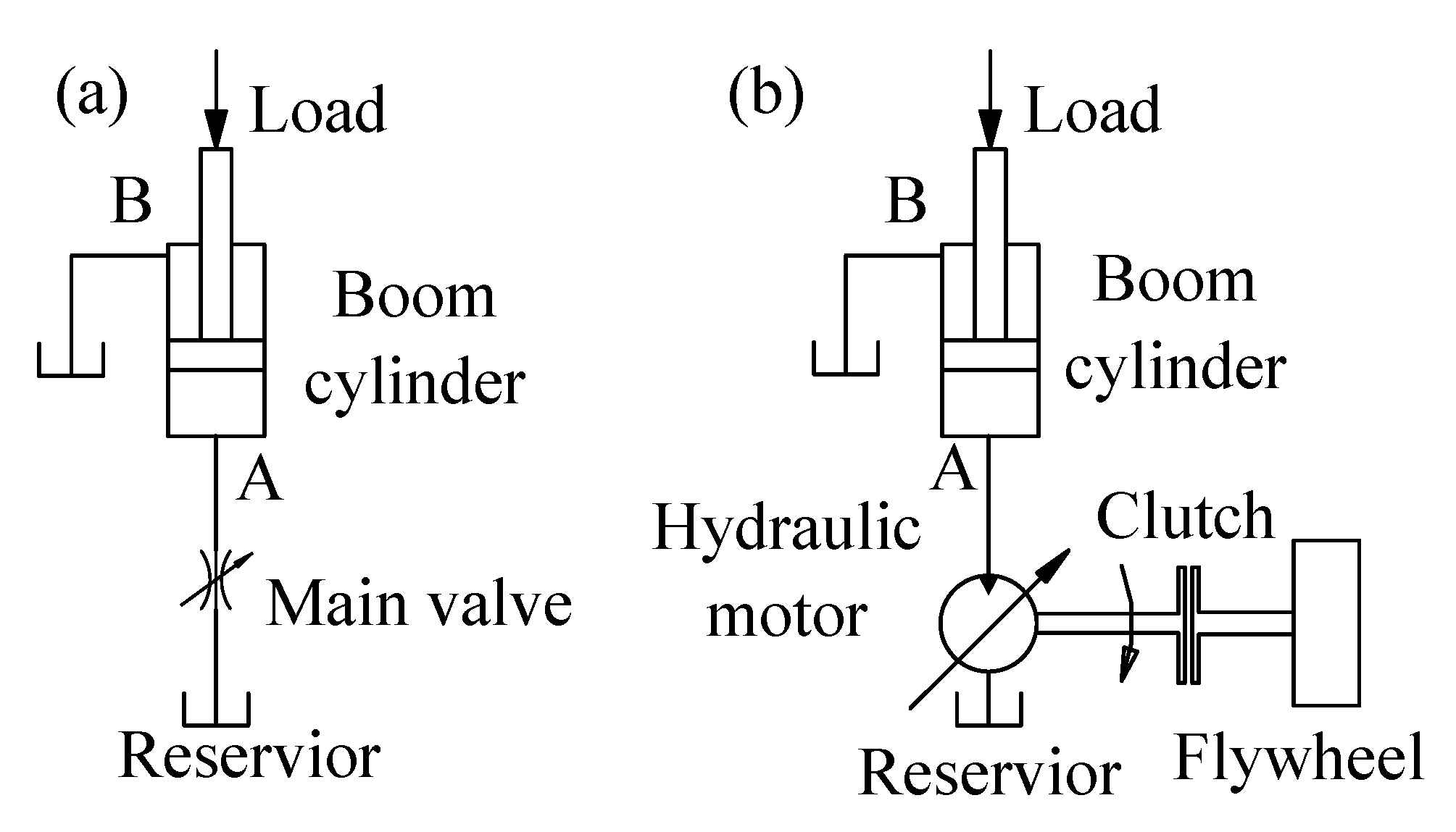
Simplified schemes of the conventional system and the proposed boom system when the boom is lowering are shown in Figure 3. As we can see, the former is a throttling control system, and the latter is a displacement control system.
3.1. Mathematical Model of the Conventional System
The flow rate of the main valve in the conventional boom system can be described by:
where kq and kc are the flow gain coefficient and flow-pressure coefficient of the main valve, respectively; xv is the opening of the main valve, and p1 is the pressure in the cap side chamber of the boom cylinder.
The flow equation of the cap side chamber of the boom cylinder can be written from the continuity equation as
where V1 is the volume of the cap side chamber; βe is the bulk modulus of the fluid; v and A1 are the piston velocity and piston area of the boom cylinder; C1 and C2 are the external and internal leakage coefficients of the boom cylinder.
The force balance equation of the boom cylinder by using Newton’s Second Law can be given
where F is the friction force acting on the boom cylinder; M is the equivalent mass of the boom and the piston of the boom cylinder, and Bp is the viscous damping coefficient.
Therefore, the transfer function of the throttling control system can be derived by using the Laplace transform method:
3.2. Mathematical Model of the Proposed System
When the boom moves downward, the PM works in the motoring mode, as shown in Figure 3b. The flow rate of the PM can be described as:
where Dm is the displacement of the PM; ω is the rotational of the PM; Cim and Cem are the coefficients of the internal and external leakage of the PM, respectively.
Similar to Equation (2), the flow equation of the cap side chamber of the boom cylinder can be given by:
As to the force balance, the Equation (3) can also be use to describe that.
The dynamic torque balance equation between the PM and flywheel can be described as
where J0 is the total moment of inertia, kgm2; Bf is the rotational viscous damping coefficient, N·m·s/rad; TL is the frictional torque load, N·m. Compared with the great inertia of the flywheel, the friction torque and viscous damping torque can be neglected.
Therefore, by using the Laplace method, the transfer function of the proposed system can be derived as:
where . As an HE is characteristic by great inertia, the friction force and viscous damping force are neglected. Therefore, we can get:
4. Control Strategy
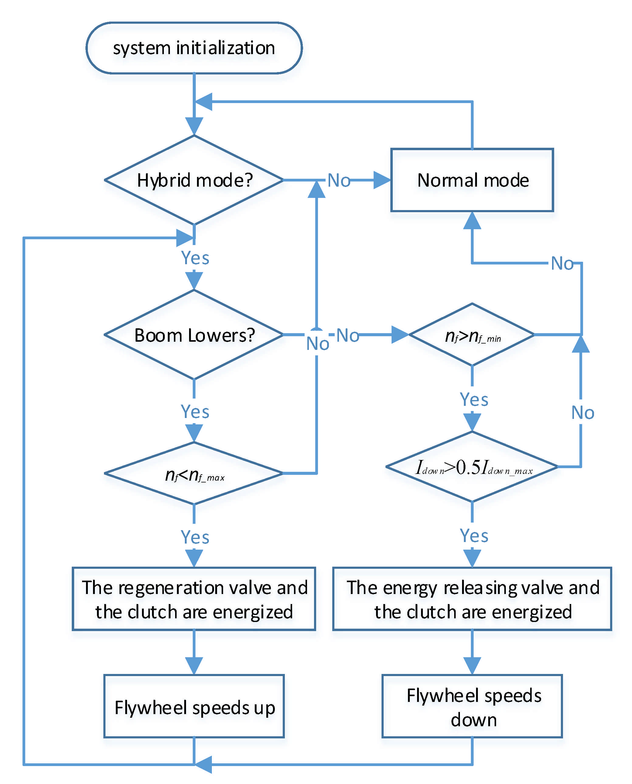
Figure 4 shows the control strategy for the proposed system. When the boom is lowered, the boom speed is regulated by controlling the displacement of the PM. In this phase, the boom potential energy is converted to pressure energy by the boom cylinder and then mechanical energy by the PM to accelerate the flywheel. There is a premise that the rotational speed of the flywheel should be smaller than its maximum speed, which is decided by its material tensile strength. When the boom moves up, the pump delivers fluid to the boom cylinder according to the control signal of the excavator operator. When the control signal of the boom-up operation and the rotational speed of the flywheel are greater than their thresholds, respectively, the PM starts to provide fluid to reduce the energy required to the engine. Herein, the threshold of the boom-up control signal is set to half of its maximum value. Such a control strategy aims to efficiently use the recaptured energy because the total efficiency of the PM is low when operating in a relatively small displacement [26]. A minimum rotational speed is used to indicate the flywheel has enough energy.
5. Simulation and Discussion
5.1. Simulation Model
To verify the energy recovery and reuse efficiency of the proposed system, a simulation model is established in AMESim software, as shown in Figure 5.
The model is composed of two parts: the original LS system and the flywheel-based ERS. This model is also used to simulate the original LS system, which is used as a baseline. This can be achieved by deactivating the energy regeneration valve. A 2/2 directional valve is used to model the flow regeneration function in the original LS system. Another 2/2 directional valve named energy-releasing valve is installed to control the output flow of the PM. An electric motor is used to model the widely used internal combustion engine because the engine always works at a constant speed [27]. Another important reason is that we only investigate the energy efficiency of the hydraulic system, but not the engine efficiency or emission. In this excavator, the boom potential energy is about 22.6 kJ. Hence, the moment of inertia of the flywheel is about 1.03 kgm2 by assuming the maximum speed is 2000 rpm. The detailed sizing process of the PM and flywheel are shown in [23]. All the parameters are set based on a 4-ton mini HE. The pertinent simulation parameters are given in Table 1. For the pump, the simulations were carried out assuming the overall efficiencies constant. As to the PM, the total efficiency map is shown in Figure 6. The efficiency of the PM varies with speed, pressure, and displacement. The LS pump displacement is controlled by the pressure compensator and flow compensator, which are integrated inside the pump.
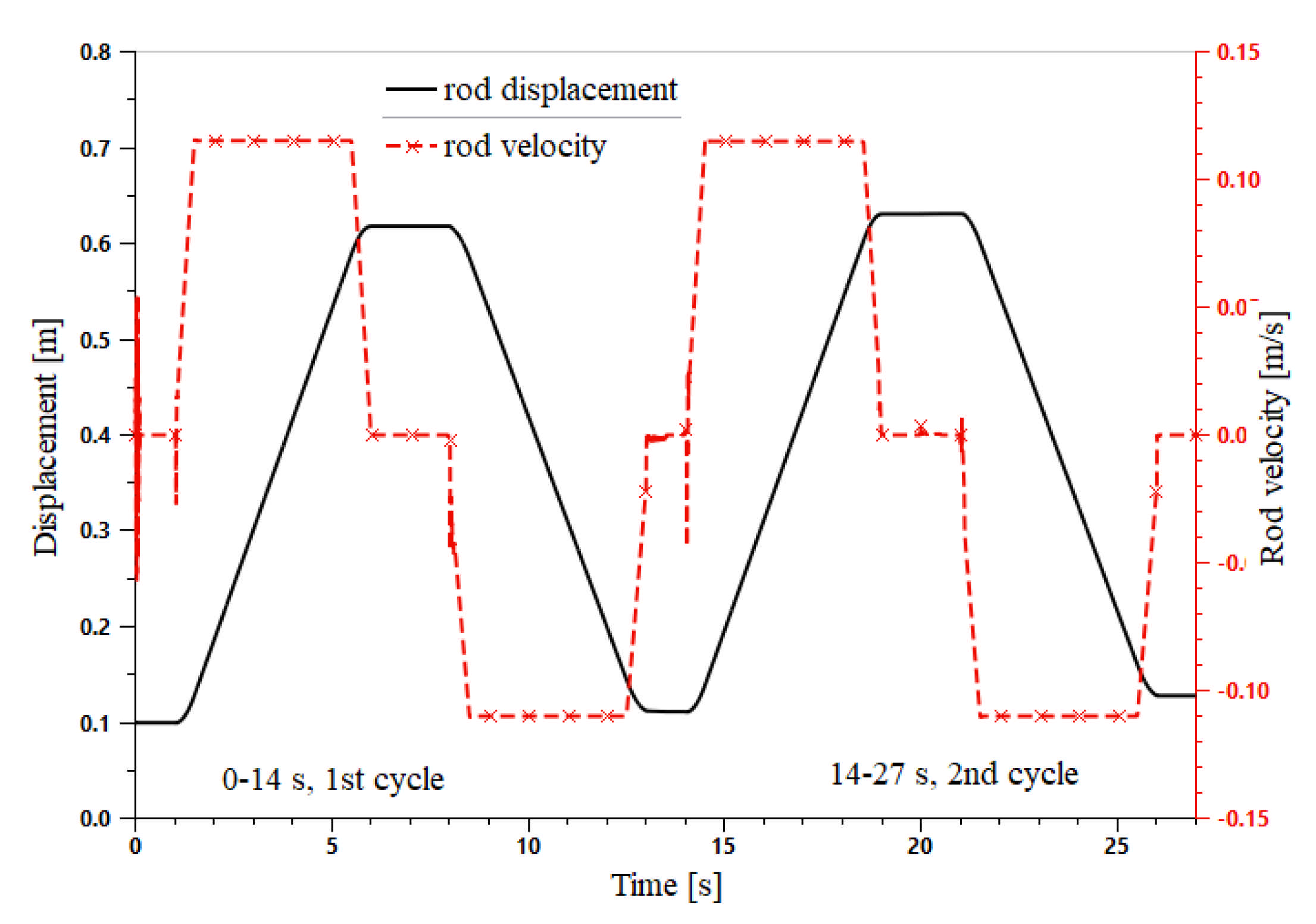
In a real HE, the boom is controlled by the operator through a joystick. The boom motion profile in simulation model is shown in Figure 7.
5.2. Simulation Results and Discussionto Validate the Energy Reutilization Effect under Different Load Conditions, Two Working Cycles Were Simulated Based on Figure 7
5.2.1. The Baseline-Conventional LS System
Figure 8 shows the rod velocity and displacement curves of the boom cylinder in the original system. In the first cycle, similar to many previous research results, the load of the boom cylinder is constant [28,29], and the useful work is null [25] in the simulation model. However, in the second lifting phase, the bucket is fully loaded. In the first lifting phase, the displacement of the boom cylinder is 0.1 m at the beginning, and the final valve is 0.618 m. Then, the boom cylinder retracted, and the exact rod displacement is 0.08 m. In the second working cycle, the traveling distances are the same as those in the first working cycle. The maximum speeds in the lifting phase and lowering phase are the same, about 0.11 m/s.
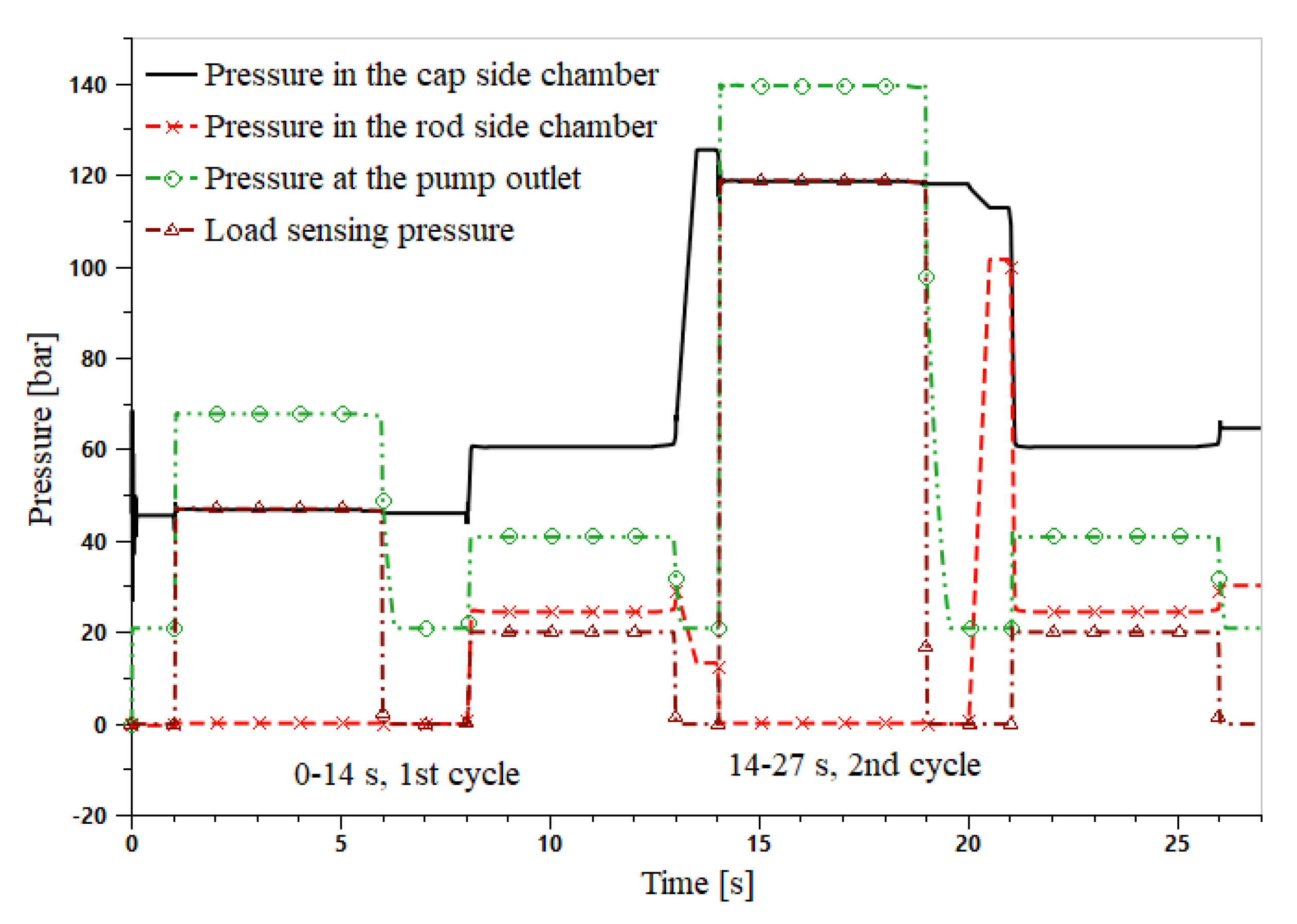
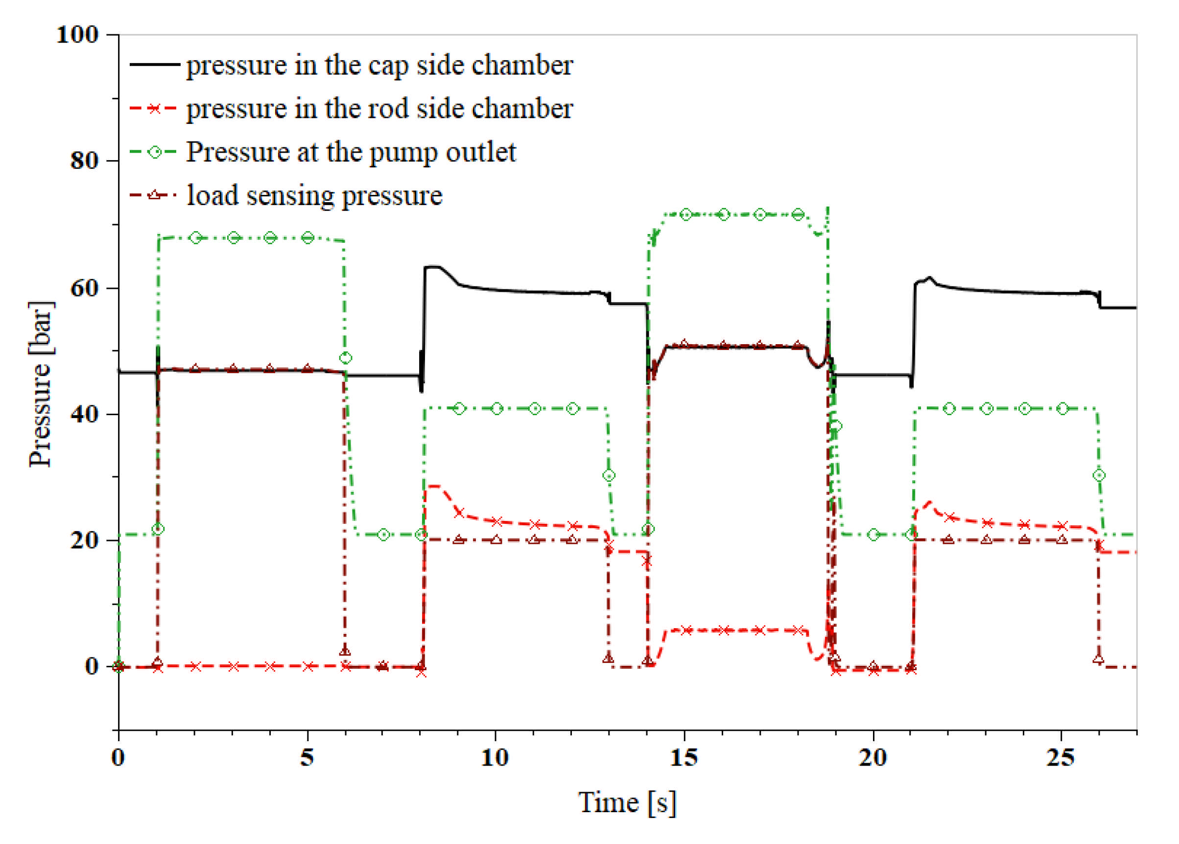
The pressure curves of the boom cylinder and pump are illustrated in Figure 9. The initial pressure in the cap side chamber of the boom cylinder is about 46 bar due to the gravity of the boom. The pressure at the pump outlet is always 20 bar higher than the LS pressure. This matches well with the character of an LS system. The LS pressure equals the pressure in the cap side chamber when the boom is moving upward and the pressure in the rod side chamber when moving down. The bucket of the excavator is fully loaded at the 14th second. So, there is a sudden rise of the pressure in the cap side chamber. The pressure in the cap side chamber has a small drop while the pressure in the rod side chamber has a big rise at the 20th second because the unloading of the bucket and all ports in the center position of the main valve are closed, and the fluid in the cap side chamber expands, and the fluid in the rod side is compressed.
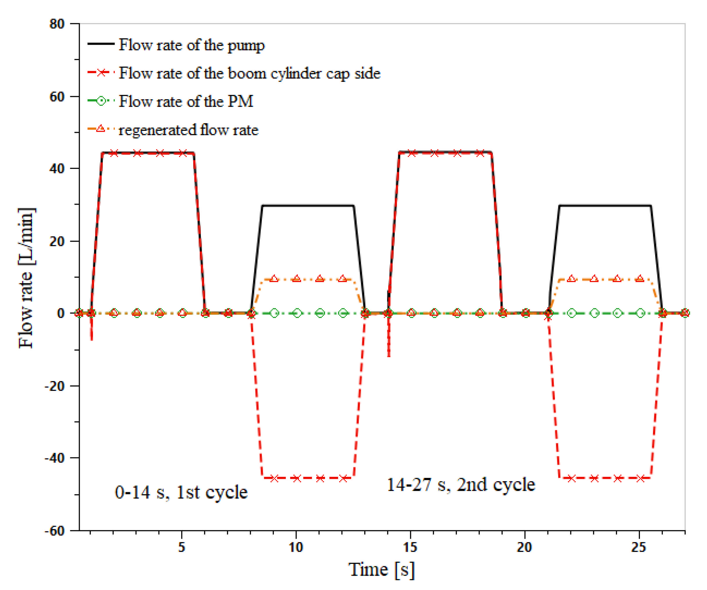
Figure 10 displays the flow rate curves of the boom cylinder, the pump, and the PM. The flow rate of the PM is always zero since the PM does not work in the original system. The regenerated flow rates in the boom-down phases show that the regeneration valve works well. When the boom cylinder retracts, part of the fluid discharged from the cap side chamber goes into the rod side chamber, so the flow rate of the LS pump is reduced.
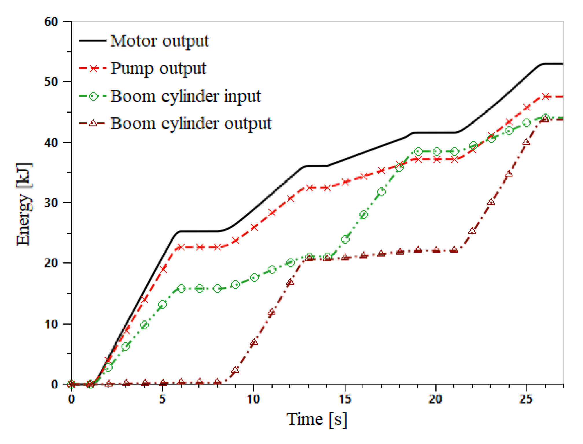
The energy consumption of the original system is illustrated in Figure 11; the motor output 32.9 kJ of energy in the first cycle and 60.2 kJ in the second phase. The difference between the two cycles is led by the load. Specifically, 25.3 kJ of energy is needed in the first lifting phase while 52.6 kJ in the second lifting phase. Additionally, one can notice that there is a gap between the motor output and the pump output, which is caused by the hydro-mechanical and volumetric losses of the pump. As to the boom cylinder energy curves, the output energy increases rapidly in the two boom-down phases due to the release of the boom gravity potential energy. The difference between the two curves is caused by the energy loss at the boom cylinder and the load.
5.2.2. The Proposed System with No Load
In this subsection, the load of the boom cylinder is constant, and the useful work is null. That means the excavator bucket is empty. Similar to Section 5.2.1, two working cycles are simulated here. In the boom down phase of the first cycle, the ERS recovers the boom potential energy, and the recovered energy is reused in the following working cycle. The rod velocity and displacement of the boom cylinder are displayed in Figure 12. The initial displacement of the boom cylinder is 0.1 m, and the final displacement is approximately 0.61 m when the boom cylinder reaches its top position. Similar to the simulation results in Figure 8, the maximum extending speeds of the boom cylinder in two lifting phases are the same, about 0.11 m/s. In the lowering phase, note that the retracting speed has a slow response process to reach its maximum value. Because the system in the lowering phase is a displacement control system by adjusting the PM displacement and it has a lower response than a throttling system. However, the mean velocity in the lowering phase is the same as that in the lifting process. That means they have similar working efficiency for a HE.
The boom cylinder and pump pressure curves of the proposed system are shown in Figure 13. The initial pressure in the cap side chamber of the boom cylinder is about 46 bar due to the gravity of the boom, which coincides with the curves in Figure 9. The boom cylinder starts to retract at 8 s. Subsequently, the pressure in both chambers have a sudden rise and resume. That is because the PM has a low response compared with the throttling system. As the name “load sensing” indicates, the pump is always delivering fluid that is 20 bar higher than the LS pressure. The LS pressure is either equal to the pressure in the cap side chamber or the pressure in the rod side chamber, whichever is greater. As aforementioned, there are two cycles for the simulation. The pressure curves of the cycles resemble each other but the pressure curve of the rod side chamber. The rod side chamber pressure in the second lifting phase is higher than that in the first lifting phase. Because the throttling area of the main valve in the second lifting phase is smaller than that in the first lifting phase, and part of the fluid is delivered by the PM. This leads to a relatively higher pressure drop.
Figure 14 and Figure 15 show the energy curves of the proposed system. During the first lifting phase, the output energy of the motor is 25.3 kJ, which is the same as that in the original system. Due to the pump loss and throttling loss of the main valve, 15.8 kJ of energy is delivered to the boom cylinder. From 8 s to 13 s, 10.8 kJ of energy is needed for the lowering phase, which is slightly more than that in the original system. This amount of the energy and the potential energy of the boom are converted into mechanical energy by the PM and then accelerate the flywheel. During the second boom lifting phase, the motor only outputs 6.4 kJ of energy. However, the boom cylinder has a similar displacement and absorbs 17.4 kJ of energy. This is because the flywheel provides the remaining energy, which is more than that of the motor. Due to the energy regeneration function and relatively higher efficiency of the ERS unit, the boom cylinder input energy exceeds the pump output energy at the end of the second lifting phase. At the end of the second working cycle, the input energy of the boom cylinder is almost equal to the output energy since the boom cylinder returned to its original position. The small difference between them is caused by the friction of the boom cylinder.
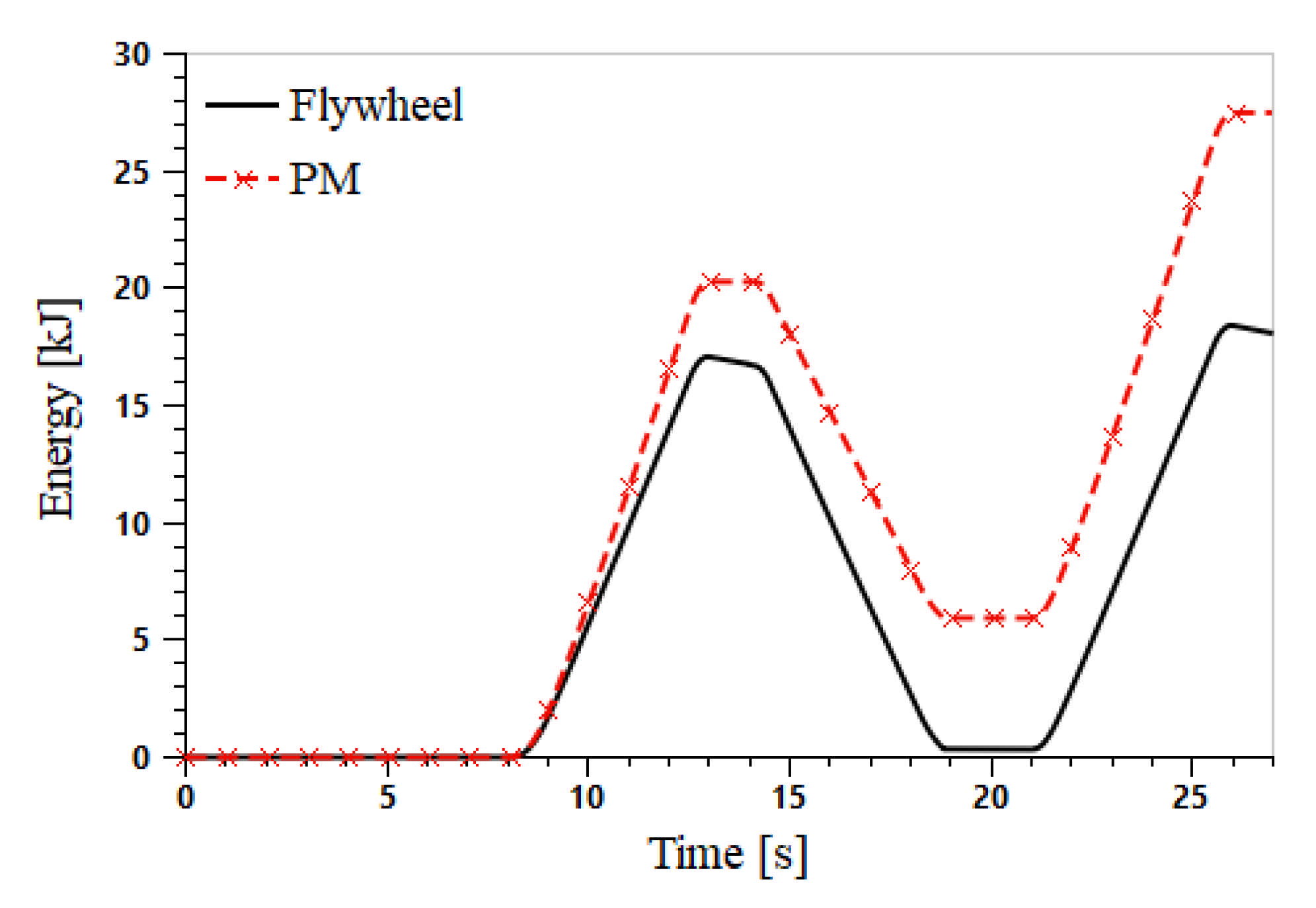
As shown in Figure 15, the energy stored in the flywheel is increasing as the boom lowers. When the boom backs to its bottom position, the energy recovery process is finished, and 17.1 kJ of energy is regenerated and stored in the flywheel. Because of the effect of its windage and friction, the kinetic energy will gradually disparate. In the second lifting phase, the PM operates in pumping mode to provide part of the fluid to the boom cylinder. The flywheel drives the PM at the cost of consuming its kinetic energy. Therefore, as aforementioned, the motor only outputs 6.4 kJ of energy in this phase, which is much less than that in the first lifting phase. That means the pump in the proposed system consumes 16.8 kJ for one cycle of boom lifting and lowering. Note that there is a difference between the energy curves of the PM and flywheel, about 5.7 kJ, as shown in Figure 15. This is caused by the hydro-mechanical and volumetric loss of the PM and the windage and friction loss of the flywheel. In the second lowering phase, the flywheel is accelerated again, and the energy gap between the PM and flywheel is getting greater and greater. The energy consumption is summarized in Table 2. If only the lifting process is considered, the energy-saving rate is 74.7%. However, the energy-saving rate is 48.9% when a whole working cycle is considered.
From Figure 14 and Figure 15, one can know that the boom cylinder outputs 20.4 kJ of energy and the flywheel absorbs 17.1 kJ in a lowering phase. Therefore, it can be calculated that the total efficiency of the PM is about 86%. Additionally, one can see that the PM outputs 14.3 kJ in the following lifting phase. Therefore, it can be calculated that the total efficiency of the PM is about 87%.
Figure 16 shows the power curves of the motor and flywheel. Here, a positive value means the flywheel absorbs energy and a negative one outputs energy. From 1 s to 6 s, the motor is the only power source while the flywheel is standstill. The maximum power of the motor is about 5.6 kW. When the boom moves down, the boom potential energy and the pressure energy entering the rod side chamber of the boom cylinder are converted to mechanical energy by the PM. Consequently, the flywheel accelerates to absorb the energy. In the second lifting phase (from 14 s), the motor is the only power source within a small period, about 0.25 s. As shown in the control strategy, the flywheel starts to provide fluid to the system when the control signal is greater than its half-maximum valve. From 14.5 s to 18.3 s, the flywheel output more power than the motor. The motor power is about 1.1 kW, and the flywheel power is about 3.7 kW. The total power is smaller than that in the first lifting phase. In the newly proposed system, only the fluid provided by the pump goes through the main valve while the fluid delivered by the PM goes into the boom cylinder directly. That means the throttling loss is much smaller than the original LS system. So, the proposed system can lift the boom with smaller power consumption. Then, the flywheel cannot output enough power and the motor output more to compensate for the gap between the flywheel output and the system’s requirement. The motor becomes the only power source again when the flywheel’s kinetic energy is exhausted. Since a throttling system has a faster response than a displacement control system, it is hard to notice that there is a switch between the two power sources. From this figure, one could see that the peak power of the motor output is reduced to 2.2 kW, which is 60.7% smaller than the original power output (5.6 kW).
The displacement curve of the PM is shown in Figure 17. In the first lifting phase, the PM displacement is zero as all the fluids are delivered by the pump, and the ERS has no energy exchange with the original system. When the boom goes down, the PM works in motoring mode to convert pressure energy to mechanical energy to accelerate the flywheel; see the energy curve in Figure 15. When the boom reaches its bottom position, the energy recovery process is over, and the flywheel keeps rotating. The kinetic energy will gradually dissipate as time goes. From the 14th second, the boom is lifted again. The PM works in pumping mode to provide pressurized fluid to the boom cylinder without the throttling of the main valve. The PM displacement increases as the flywheel slows down. When the PM reaches its maximum displacement, the motor outputs more energy to satisfy the system’s power demand.
5.2.3. The Proposed System with a Fully Loaded Bucket
In this subsection, to investigate the energy efficiency in a fully loaded case, the bucket is empty in the first working cycle, and the bucket is fully loaded in the second working cycle.
The rod velocity and displacement curves in the proposed system with a fully loaded bucket are shown in Figure 18. The rod velocity and displacement curves here resemble those in Figure 12.
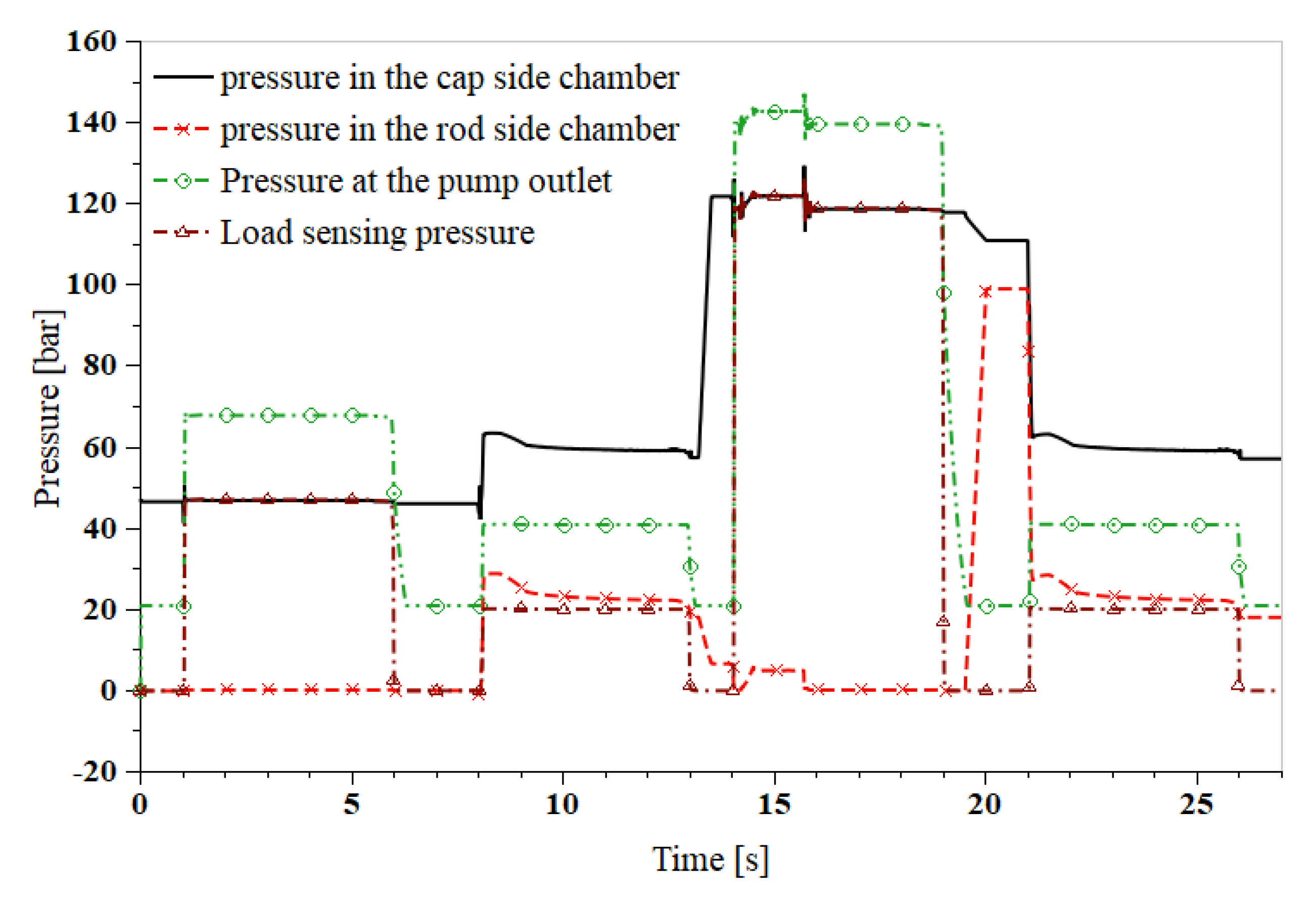
The boom cylinder and pump pressure curves of the proposed system with a fully loaded bucket are shown in Figure 19. The pressure in the second lifting phase (about 140 bar at the pump outlet) in Figure 19 is much higher than that in Figure 13 (about 70 bar at the pump outlet) due to the load in the bucket. Note that the pressures from the 14th to 16th second (the first half) are 4 bar higher than the remaining part (the second half) of the second lifting phase. The reason is that from the 14th to 16th second, the throttling area of ports B to T in the main valve is relatively small as only part of the fluid entered into the boom cylinder is directed by the main valve and the rest are provided by the PM. Furthermore, all the fluid is provided by the main valve, so both the throttling areas of ports P to A and ports B to T get larger than before.
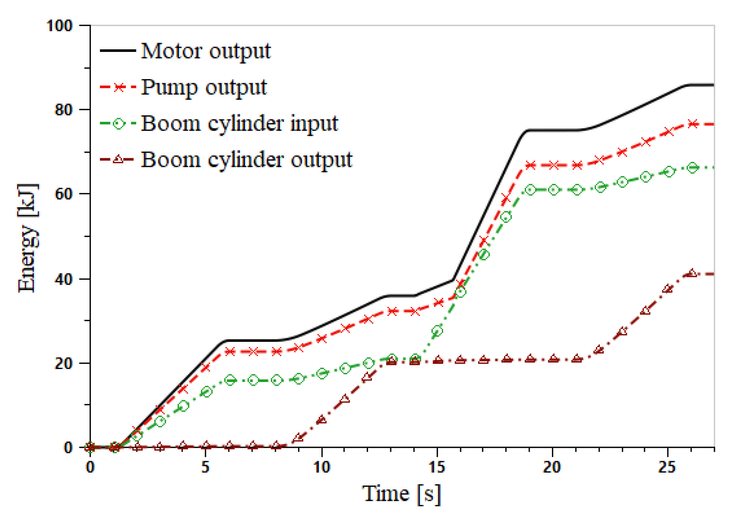
In Section 5.2.2, the flywheel’s kinetic energy is exhausted by the end of the second lifting process. However, this case is that the bucket is empty. So, one can conclude that the kinetic energy will be exhausted in a shorter period if the bucket is fully loaded. Figure 20 shows the Energy consumption curves of the proposed system with a fully loaded bucket. In the first working cycle, the curves in Figure 20 are the same as those in Figure 14. In the second lifting phase, due to the load in the bucket, the motor outputs 39.3 kJ of energy, which is much more than that in the first lifting phase but less than that in the original system. Additionally, it can be concluded that the energy needed to lift the boom is more than that needed to lift the load in the bucket. One could notice that there is a big difference between the input and output of the boom cylinder, which is used to lift the load. The energy consumption is summarized in Table 2. In cases where the lifting process is the only consideration, the energy-saving rate is 25.1%. However, the energy-saving rate is 16.9% when considering a whole working cycle. The main reason is that the energy used to lift the load accounts for the largest portion among all energy consumers.
From Figure 20 and Figure 21, one can know that the boom cylinder outputs 19.9 kJ of energy and the flywheel absorbs 16.7 kJ in a lowering phase. Therefore, it can be calculated that the total efficiency of the PM is about 84%. It is normal that these data are slightly different from the data in Section 5.2.2 because the traveling distances are also not quite the same. Additionally, one can see that the flywheel delivers 16.7 kJ of energy and the PM outputs 10.7 kJ in a lifting phase. Therefore, it can be calculated that the total efficiency of the PM is about 64%. The change of the working area of the PM is the main reason why the PM’s total efficiency decreases so much. This is also one reason for the decrease in the energy-saving rate of a fully loaded condition, see Table 2.
The energy curves of the PM and flywheel are displayed in Figure 21. From this figure, one can know that the flywheel absorbs 16.7 kJ of energy in a boom lowering phase. When the boom goes up, the PM provides energy to the system by decelerating the flywheel. Similar to Figure 15, the efficiencies of the PM and flywheel push the energy curves to go apart as time goes.
To better understand the energy distribution, the energy flow of the two systems under different load conditions are shown in Figure 22. Since the boom cylinder is these four figures have very similar velocity and displacement profile, the amounts of energy lost at the boom cylinder are the same. In Figure 22a,c, the useful work is zero and are the energy provided by the motor is wasted. When the excavator bucket is fully loaded, the effective energy efficiencies in the conventional LS system and the proposed system are 39.4% and 47.6%, respectively, as displayed by Figure 22b,d. The flywheel can recover energy no matter how much the load is; hence, the total energy output by the motor is reduced. Specifically, the motor output 16.9 kJ of energy when the excavator bucket is empty and 50.0 kJ when fully loaded. Compared with the conventional system, the energy is reduced by 48.9% and 16.9%. In any case of the four, the energy lost at the main valve is more than any other component. That means more effort should be made to reduce the energy loss here to improve energy efficiency. The second one is the energy recovery system. The PM efficiency has a more impact on the total efficiency of the ERS than the flywheel efficiency. The PM efficiency varies a lot when the displacement, pressure, or rotational speed varies, while the energy loss of the flywheel is mainly caused by the windage. From this point, control the PM work in a high-efficiency area will greatly impact the energy reuse efficiency. There is a minor difference between the energy used to lift the fully load bucket, which is caused by the minor position difference of the boom cylinder.
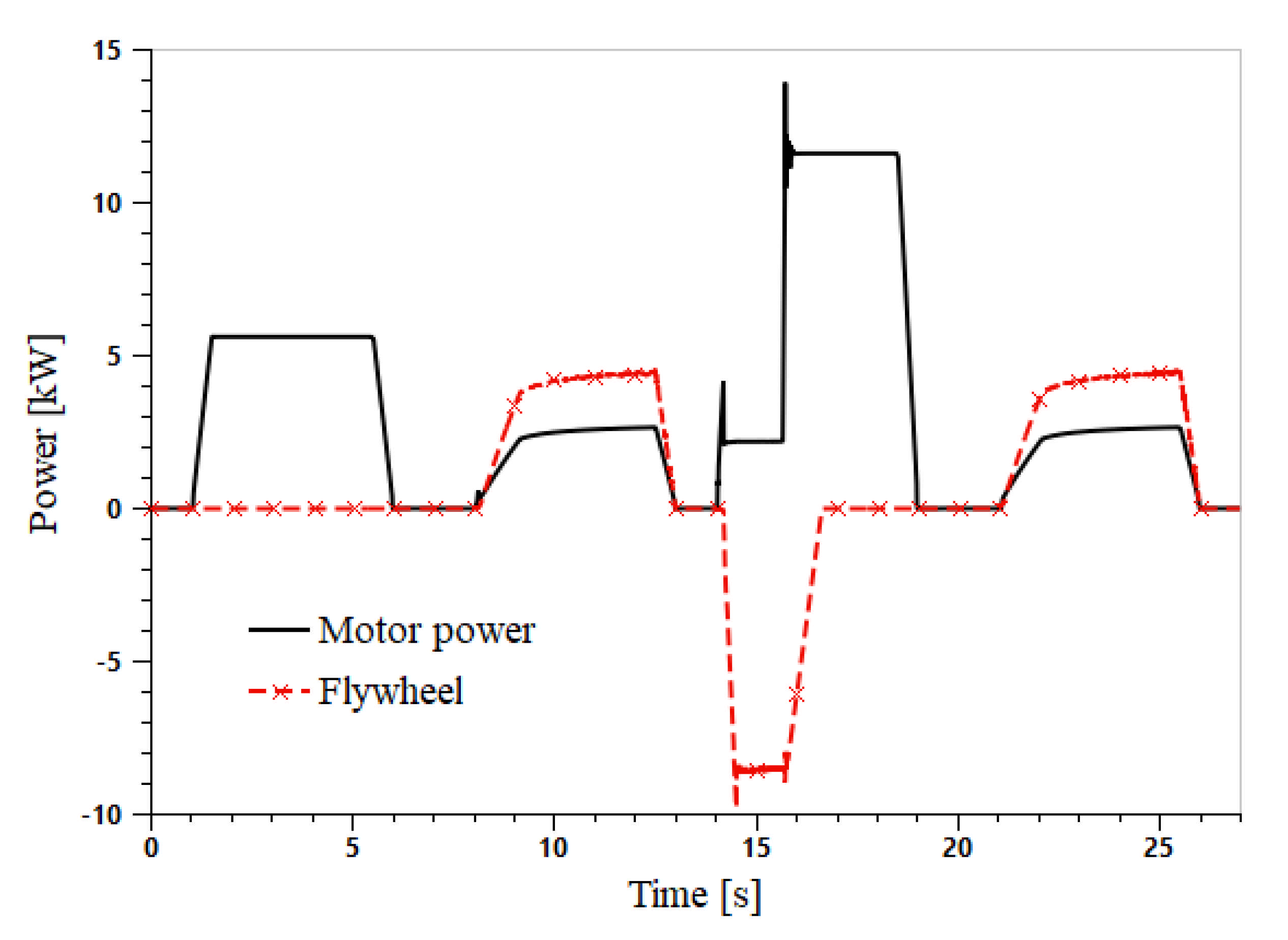
From the power curves shown in Figure 23, in the first lifting phase, the flywheel has no energy exchange with the system and absorbs energy when the boom moves down. In the second lifting phase, the flywheel provides more energy than the motor from the 14th to 16th second. After that, the motor becomes the only power source of the system since the kinetic energy in the flywheel has been exhausted. Those coincide with the curves in Figure 21. Since the flywheel does not work for the whole lifting phase, we do not discuss the peak power reduction effect more.
Figure 24 shows the PM displacement curve when the excavator bucket is fully loaded. The curve is very similar to that in Figure 17. The main difference appears in the second boom lifting phase. In this figure, the PM displacement hits its maximum value in 2 s, which is much shorter than that in Figure 17. Because when the bucket is fully loaded, the system needs greater power to lift the boom. A similar conclusion can be drawn from Figure 20 and Figure 23.
5.2.4. Comparison with Other Research and Discussion
As aforementioned in Section 1, a hydraulic accumulator-based integrated drive and energy recuperation system is proposed in reference [9]. A three-chamber hydraulic cylinder is used to replace the commonly used double-chamber cylinder. One feature of the system is that one chamber of the three-chamber hydraulic cylinder is connected to the hydraulic accumulator. A 6 t HE is chosen as a study case, and experiments show that this novel system can reduce the energy consumption by 50.1% when the bucket is empty. Furthermore, the peak power of the hydraulic pump is reduced by 64.9%. The energy-saving and power reduction effect is similar to that in this paper.
The energy-saving effect is achieved by the balanced effect of the hydraulic accumulator. It is a highly efficient design since direct connection reduces energy conversion as much as possible. Another merit of schemes using accumulators as energy storage devices is a relatively low manufacture cost and mature manufacturing technique. Currently, a lot of literature reports that a flywheel with a similar power capacity is higher than a hydraulic accumulator, especially a flywheel made of composite material. However, a flywheel can store more energy than a hydraulic accumulator with equivalent mass [30], which makes it more completive in cases where a large amount of energy to be recovered.
Inspired by the reference [9], the authors believe that more effort should be made to improve the energy efficiency of the energy converter if a flywheel is used as the energy storage device. In this paper, a displacement variable PM is used as the energy converter. This gives us more freedom to control the energy-releasing process.
6. Conclusions
This work responds to the need for companies to move towards cleaner productivity in the construction machinery field by identifying an appropriate means to recover the otherwise wasted energy and reuse it in the following work process. It can be concluded as follows:
- A new LS system with a flywheel-based ERS is proposed and analyzed. A hydraulic PM is employed in this system as a converter, and a flywheel is used as an energy storage device. The PM converts the pressure energy in the boom cylinder into kinetic energy to accelerate the flywheel when the boom moves down. The recaptured energy is reutilized by pumping fluid to the boom cylinder when the boom goes up. This reduces the power demand of the original engine.
- AMESim software is used to model the proposed system and to investigate the energy-saving effect. Simulation results show that, in a non-loaded cycle of boom lifting and lowering process, the proposed system reduces as much as 48.9% energy consumption compared with an LS system without an ERS. However, in fully-loaded cases, the energy-saving rate decreases to 16.9%. More energy is needed to lift the load, and the recovered energy is almost constant, so the energy-saving rate decreases. This is the main reason. The change of working area is another reason for this.
This research indicates the flywheel-based scheme is promising to develop a more sustainable future of HEs. In the future, it is worth building a prototype to investigate its energy-saving effect, especially a fuel-saving-based effect. Advanced energy management should be developed to help the PM operate in high-efficiency areas for better reuse of the recovered energy.
7. Patents
J. Li, W. Zhang. Electrohydraulic control system for potential energy recovery and reutilization for construction machinery boom. CN: 201810008336.0, 05 Feburary 2021.
J. Li, D. Xu, S. Li, et al. Energy-saving boom system for hydraulic excavator with load sensing system. CN: CN112127415A, 25 December 2020.
Author Contributions
Conceptualization and methodology, J.L.; software, validation, investigation, and writing—original draft preparation, J.L. and Y.H.; writing—review and editing and supervision, project administration and funding acquisition, J.L. and S.L. All authors have read and agreed to the published version of the manuscript.
Funding
This research was funded by the Jiangsu Overseas Visiting Scholar Program for the University Prominent Young and Middle-aged Teachers and Presidents 2018(2018-3), the Jiangsu Qing Lan Project (201812), the Industry R&D Project of Xuzhou College of Industrial Technology (2019131-1), Xuzhou College of Industrial Technology Science and Technology Foundation (XGY2020EA05 and XGY2020HA05), and the Jiangsu Science and Technology Association Youth Science and technology talent lifting project (2018–202).
Institutional Review Board Statement
Not applicable.
Informed Consent Statement
Not applicable.
Data Availability Statement
Data sharing not applicable.
Acknowledgments
We would like to express our gratitude to the anonymous reviewers and friends who helped us in the process of completing this paper.
Conflicts of Interest
The authors declare no conflict of interest.
References
- Zhang, S.; Jiang, J.; Lian, G. Research on recoverable energy distribution of hydraulic excavator. J. Zhengzhou Univ. 2014, 35, 120–124. [Google Scholar] [CrossRef]
- Do, T.C.; Dang, T.D.; Dinh, T.Q.; Ahn, K.K. Developments in energy regeneration technologies for hydraulic excavators: A review. Renew. Sustain. Energy Rev. 2021, 145, 111076. [Google Scholar] [CrossRef]
- Wang, T.; Wang, Q. Efficiency analysis and evaluation of energy-saving pressure-compensated circuit for hybrid hydraulic excavator. Autom. Constr. 2014, 47, 62–68. [Google Scholar] [CrossRef]
- Lin, T.; Wang, Q.; Hu, B.; Wen, G. Research on the energy regeneration systems for hybrid hydraulic excavators. Autom. Constr. 2010, 19, 1016–1026. [Google Scholar] [CrossRef]
- Lin, T.; Wang, Q. Hydraulic accumulator-motor-generator energy regeneration system for a hybrid hydraulic excavator. Chin. J. Mech. Eng. 2012, 25, 1121–1129. [Google Scholar] [CrossRef]
- Yu, Y.; Ahn, K.K. Optimization of energy regeneration of hybrid hydraulic excavator boom system. Energy Convers. Manag. 2019, 183, 26–34. [Google Scholar] [CrossRef]
- Do, T.C.; Nguyen, D.G.; Dang, T.D.; Ahn, K.K. A Boom Energy Regeneration System of Hybrid Hydraulic Excavator Using Energy Conversion Components. Actuators 2021, 10, 1. [Google Scholar] [CrossRef]
- Hao, Y.; Quan, L.; Cheng, H.; Xia, L.; Ge, L.; Zhao, B. Potential energy directly conversion and utilization methods used for heavy duty lifting machinery. Energy 2018, 155, 242–251. [Google Scholar] [CrossRef]
- Xia, L.; Quan, L.; Ge, L.; Hao, Y. Energy efficiency analysis of integrated drive and energy recuperation system for hydraulic excavator boom. Energy Convers. Manag. 2018, 156, 680–687. [Google Scholar] [CrossRef]
- Li, Z.; Wang, C.; Quan, L.; Hao, Y.; Ge, L.; Xia, L. Study on energy efficiency characteristics of the heavy-duty manipulator driven by electro-hydraulic hybrid active-passive system. Autom. Constr. 2021, 125, 103646. [Google Scholar] [CrossRef]
- Joo, C.; Stangl, M. Application of Power Regenerative Boom system to excavator. In Proceedings of the 10th International Fluid Power Conference, Dresden, Germany, 8–10 March 2016; pp. 175–184. Available online: https://tud.qucosa.de/api/qucosa%3A29389/attachment/ATT-0/ (accessed on 8 June 2021).
- Casoli, P.; Gambarotta, A.; Pompini, N.; Riccò, L. Hybridization methodology based on DP algorithm for hydraulic mobile machinery—Application to a middle size excavator. Autom. Constr. 2016, 61, 42–57. [Google Scholar] [CrossRef]
- Bui, N.M.T.; Dinh, Q.T.; Lee, S.Y.; Lee, S.Y.; Ahn, K.K. Study on energy regeneration system for hybrid hydraulic excavator. In Proceedings of the 2015 International Conference on Fluid Power and Mechatronics, Harbin, China, 5–7 August 2015; pp. 1349–1354. [Google Scholar] [CrossRef]
- Vukovic, M.; Leifeld, R. STEAM-a hydraulic hybrid architecture for excavators. In Proceedings of the 10th International Fluid Power Conference, Dresden, Germany, 8–10 March 2016; pp. 151–162. Available online: https://core.ac.uk/reader/236373201 (accessed on 18 September 2020).
- Ge, L.; Quan, L.; Li, Y.; Zhang, X.; Yang, J. A novel hydraulic excavator boom driving system with high efficiency and potential energy regeneration capability. Energy Convers. Manag. 2018, 166, 308–317. [Google Scholar] [CrossRef]
- Shen, W.; Jiang, J.; Su, X.; Karimi, H.R. Energy-saving analysis of hydraulic hybrid excavator based on common pressure rail. Sci. World J. 2013, 2013, 560694. [Google Scholar] [CrossRef]
- Liu, Y.; Xu, Z.; Hua, L.; Zhao, X. Analysis of energy characteristic and working performance of novel controllable hydraulic accumulator with simulation and experimental methods. Energy Convers. Manag. 2020, 221, 113196. [Google Scholar] [CrossRef]
- Wasbari, F.; Bakar, R.A.; Gan, L.M.; Tahir, M.M.; Yusof, A.A. A review of compressed-air hybrid technology in vehicle system. Renew. Sustain. Energy Rev. 2017, 67, 935–953. [Google Scholar] [CrossRef] [Green Version]
- Tianliang, L.; Qiang, C.; Haoling, R.; Weiping, H.; Qihuai, C.; Shengjie, F. Boom energy recovery system with auxiliary throttle based on hybrid excavator. Proc. Inst. Mech. Eng. Part C J. Mech. Eng. Sci. 2016, 231, 4250–4262. [Google Scholar] [CrossRef]
- Hedlund, M.; Lundin, J.; de Santiago, J.; Abrahamsson, J.; Bernhoff, H. Flywheel Energy Storage for Automotive Applications. Energies 2015, 8, 10636–10663. [Google Scholar] [CrossRef] [Green Version]
- DHand, A.; PULLEN, K. Review of Battery Electric Vehicle Propulsion Systems incorporating Flywheel Energy Storage. Int. J. Automot. Technol. 2015, 16, 487–500. [Google Scholar] [CrossRef] [Green Version]
- Ricardo. Ricardo to Showcase ‘TorqStor’ High Efficiency Flywheel Energy Storage at CONEXPO. Available online: https://ricardo.com/news-and-media/news-and-press/ricardo-to-showcase-%E2%80%98torqstor%E2%80%99-high-efficiency-fly (accessed on 4 December 2019).
- Li, J.; Zhao, J.; Zhang, X. A Novel Energy Recovery System Integrating Flywheel and Flow Regeneration for a Hydraulic Excavator Boom System. Energies 2020, 13, 315. [Google Scholar] [CrossRef] [Green Version]
- Mahato, A.C.; Ghoshal, S.K. An Overview of Energy Savings Approaches on Hydraulic Drive Systems. Int. J. Fluid Power 2020, 21, 81–118. [Google Scholar] [CrossRef]
- Bedotti, A.; Campanini, F.; Pastori, M.; Riccò, L.; Casoli, P. Energy saving solutions for a hydraulic excavator. Energy Procedia 2017, 126, 1099–1106. [Google Scholar] [CrossRef]
- Kwon, H.; Ivantysynova, M. System Characteristics Analysis for Energy Management of Power-Split Hydraulic Hybrids. Energies 2020, 13, 1837. [Google Scholar] [CrossRef] [Green Version]
- Gong, J.; Zhang, D.; Liu, C.; Zhao, Y.; Hu, P.; Quan, W. Optimization of electro-hydraulic energy-savings in mobile machinery. Autom. Constr. 2019, 98, 132–145. [Google Scholar] [CrossRef]
- Chen, Q.; Lin, T.; Ren, H.; Fu, S. Novel potential energy regeneration systems for hybrid hydraulic excavators. Math. Comput. Simul. 2019, 163, 130–145. [Google Scholar] [CrossRef]
- Wang, T.; Wang, Q. Design and analysis of compound potential energy regeneration system for hybrid hydraulic excavator. Proc. Inst. Mech. Eng. Part I J. Syst. Control Eng. 2012, 226, 1323–1334. [Google Scholar] [CrossRef]
- Buchroithner, A.; Wegleiter, H. Flywheel Energy Storage Systems Compared to Competing Technologies for Grid Load Mitigation in EV Fast-Charging Applications. In Proceedings of the 2018 IEEE 27th International Symposium on Industrial Electronics (ISIE), Cairns, Australia, 13–15 June 2018; pp. 508–514. [Google Scholar] [CrossRef]
Figure 1.
The original load sensing system for a conventional hydraulic excavator boom.

Figure 2.
The proposed load sensing system with a flywheel-based energy recovery system.

Figure 3.
The simplified scheme: (a) conventional boom system; (b) proposed boom system.

Figure 4.
A flow chart of the control strategy.

Figure 5.
The simulation model established in AMESim.

Figure 6.
The pump/motor efficiency.

Figure 7.
The duty cycle for the boom motion.

Figure 8.
Rod velocity and displacement curves of boom cylinder in the original system.

Figure 9.
Boom cylinder and pump pressure curves in the original system.

Figure 10.
Flow rate curves in the original system.

Figure 11.
Energy consumption of the original system.

Figure 12.
The boom cylinder rod velocity and displacement of the proposed system without useful load.
Figure 12.
The boom cylinder rod velocity and displacement of the proposed system without useful load.

Figure 13.
Boom cylinder and pump pressure curves of the proposed system with an empty bucket.

Figure 14.
Energy consumption of the proposed system with an empty bucket.

Figure 15.
Energy curves of the flywheel and PM of the proposed system when the excavator bucket is empty.
Figure 15.
Energy curves of the flywheel and PM of the proposed system when the excavator bucket is empty.

Figure 16.
Power curves of the motor and flywheel when the excavator bucket is empty.

Figure 17.
The PM displacement curve of the proposed system when the excavator bucket is empty.

Figure 18.
The boom cylinder rod velocity and displacement of the proposed system when the excavator bucket is fully loaded.
Figure 18.
The boom cylinder rod velocity and displacement of the proposed system when the excavator bucket is fully loaded.

Figure 19.
Boom cylinder and pump pressure curves of the proposed system with a fully loaded bucket.
Figure 19.
Boom cylinder and pump pressure curves of the proposed system with a fully loaded bucket.

Figure 20.
Energy consumption of the proposed system with a fully loaded bucket.

Figure 21.
Energy curves of the flywheel and PM of the proposed system when the excavator bucket is fully loaded.
Figure 21.
Energy curves of the flywheel and PM of the proposed system when the excavator bucket is fully loaded.

Figure 22.
Sankey diagrams of energy flow. (a) The energy flow of the conventional load sensing system, non-loaded; (b) The energy flow of the conventional load sensing system, fully loaded; (c) The energy flow of the proposed system, non-loaded; (d) The energy flow of the proposed system, fully loaded.


Figure 23.
Power curves of the motor and flywheel when the excavator bucket is fully loaded.

Figure 24.
The PM displacement of the proposed system when the excavator bucket is full.


Table 1.
The pertinent parameters of the simulation model [23].
Table 1.
The pertinent parameters of the simulation model [23].
| Component | Parameters | Value |
|---|---|---|
| LS Pump | Hydro-mechanical efficiency | 0.93 |
| Volumetric efficiency | 0.96 | |
| Maximum displacement (ml/rev) | 45 | |
| Pressure difference set by the flow compensator (bar) | 20 | |
| Maximum pressure set by the pressure compensator (bar) | 280 | |
| Pump/motor | Efficiency | see Figure 6 |
| Maximum displacement (ml/rev) | 71 | |
| Boom cylinder | Piston diameter (mm) | 90 |
| Rod diameter (mm) | 53 | |
| Stroke (m) | 0.6 | |
| Initial displacement | 0.1 | |
| Viscous friction coefficient [N/(m/s)] | 800 | |
| Stiction force (N) | 600 | |
| Coulomb friction force (N) | 600 | |
| Flywheel | Moment of inertia (kg·m2) | 1.03 |
| Viscous damping coefficient [N·m/(rev/min)] | 0.001 |
Table 2.
Summarization of energy-saving effect.
| Load of the Excavator Bucket | Motor Energy | Original System/kJ | Proposed System/kJ | Energy-Saving Rate/% |
|---|---|---|---|---|
| Null (empty bucket) | Needed to lift boom | 25.3 | 6.4 | 74.7 |
| Needed in one cycle | 32.9 | 16.8 | 48.9 | |
| Fully loaded (full bucket) | needed to lift boom | 52.6 | 39.3 | 25.3 |
| Needed in one cycle | 60.2 | 50.0 | 16.9 |
Publisher’s Note: MDPI stays neutral with regard to jurisdictional claims in published maps and institutional affiliations. |
© 2021 by the authors. Licensee MDPI, Basel, Switzerland. This article is an open access article distributed under the terms and conditions of the Creative Commons Attribution (CC BY) license (https://creativecommons.org/licenses/by/4.0/).
Share and Cite
MDPI and ACS Style
Li, J.; Han, Y.; Li, S. Flywheel-Based Boom Energy Recovery System for Hydraulic Excavators with Load Sensing System. Actuators 2021, 10, 126. https://0-doi-org.brum.beds.ac.uk/10.3390/act10060126
AMA Style
Li J, Han Y, Li S. Flywheel-Based Boom Energy Recovery System for Hydraulic Excavators with Load Sensing System. Actuators. 2021; 10(6):126. https://0-doi-org.brum.beds.ac.uk/10.3390/act10060126
Chicago/Turabian StyleLi, Jiansong, Yu Han, and Shaohui Li. 2021. "Flywheel-Based Boom Energy Recovery System for Hydraulic Excavators with Load Sensing System" Actuators 10, no. 6: 126. https://0-doi-org.brum.beds.ac.uk/10.3390/act10060126
Note that from the first issue of 2016, this journal uses article numbers instead of page numbers. See further details here.