
A Case Study on the Detection and Prognosis of Internal Leakages in Electro-Hydraulic Flight Control Actuators


Abstract
:
1. Introduction
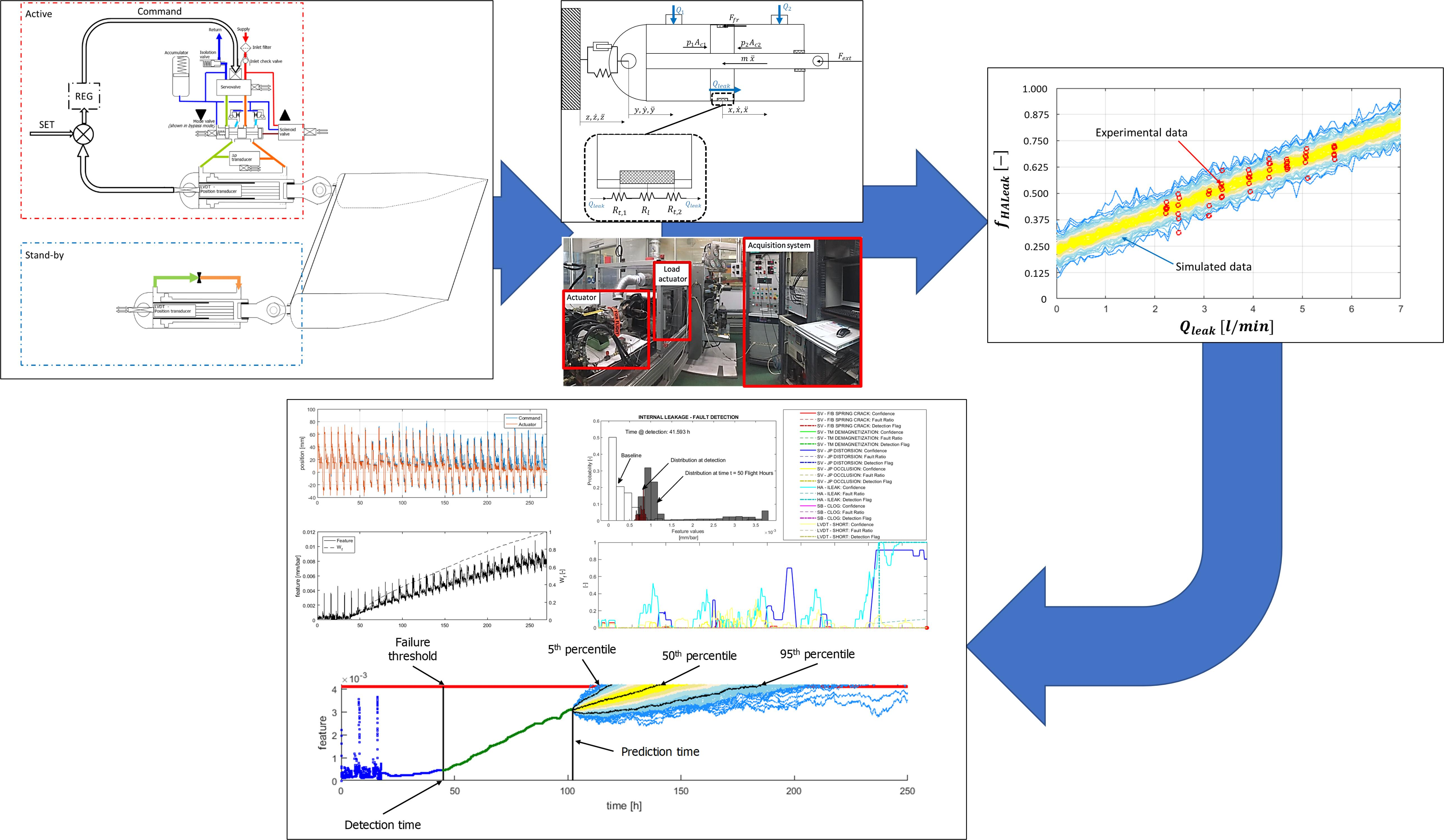
2. Case Study
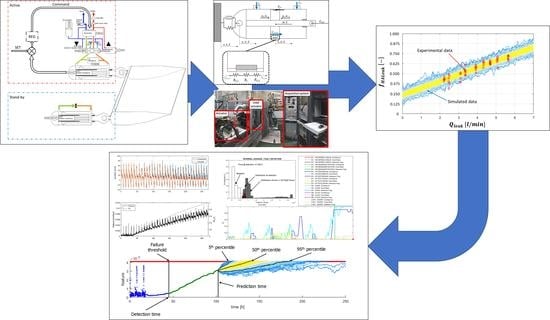
3. Materials and Methods
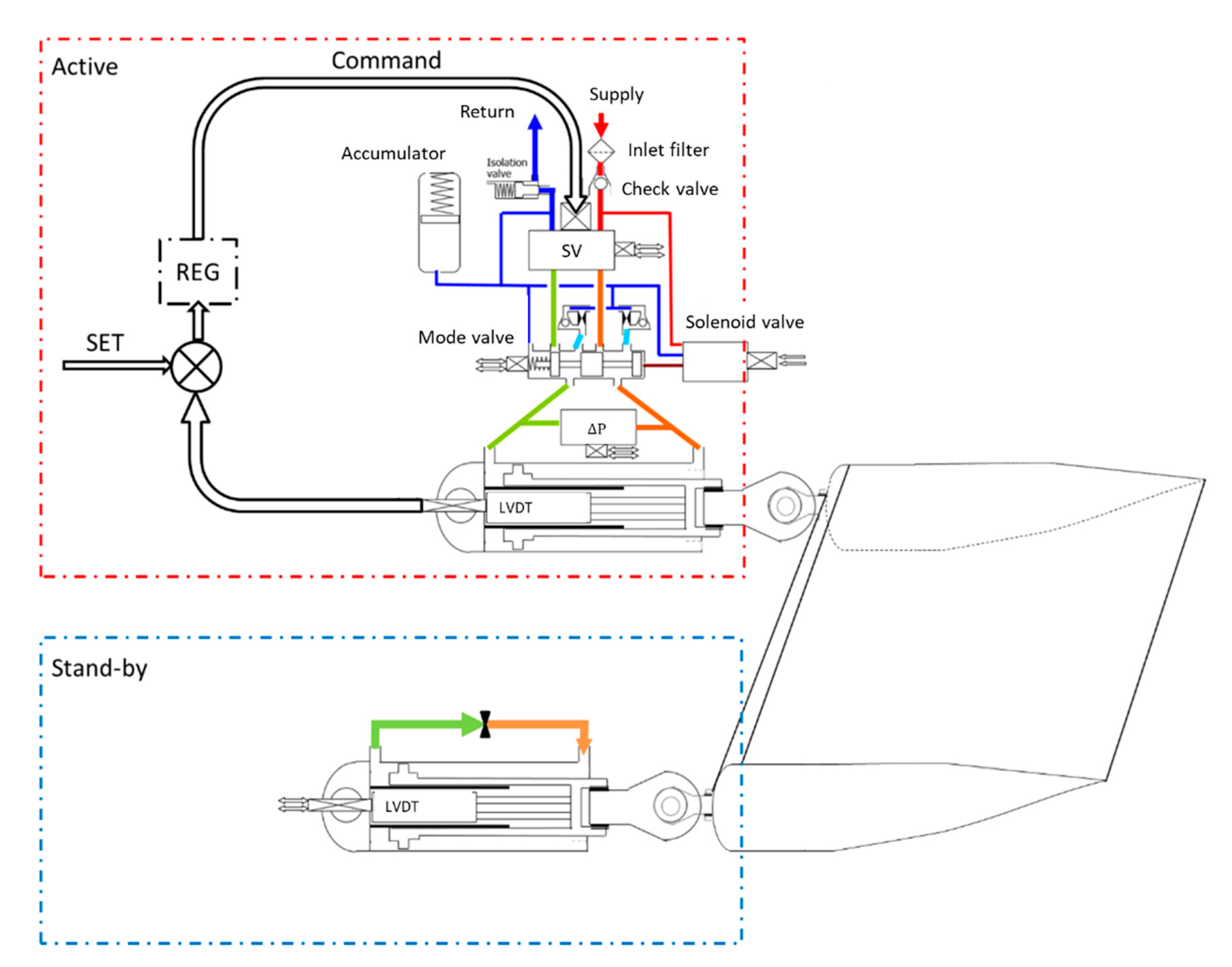
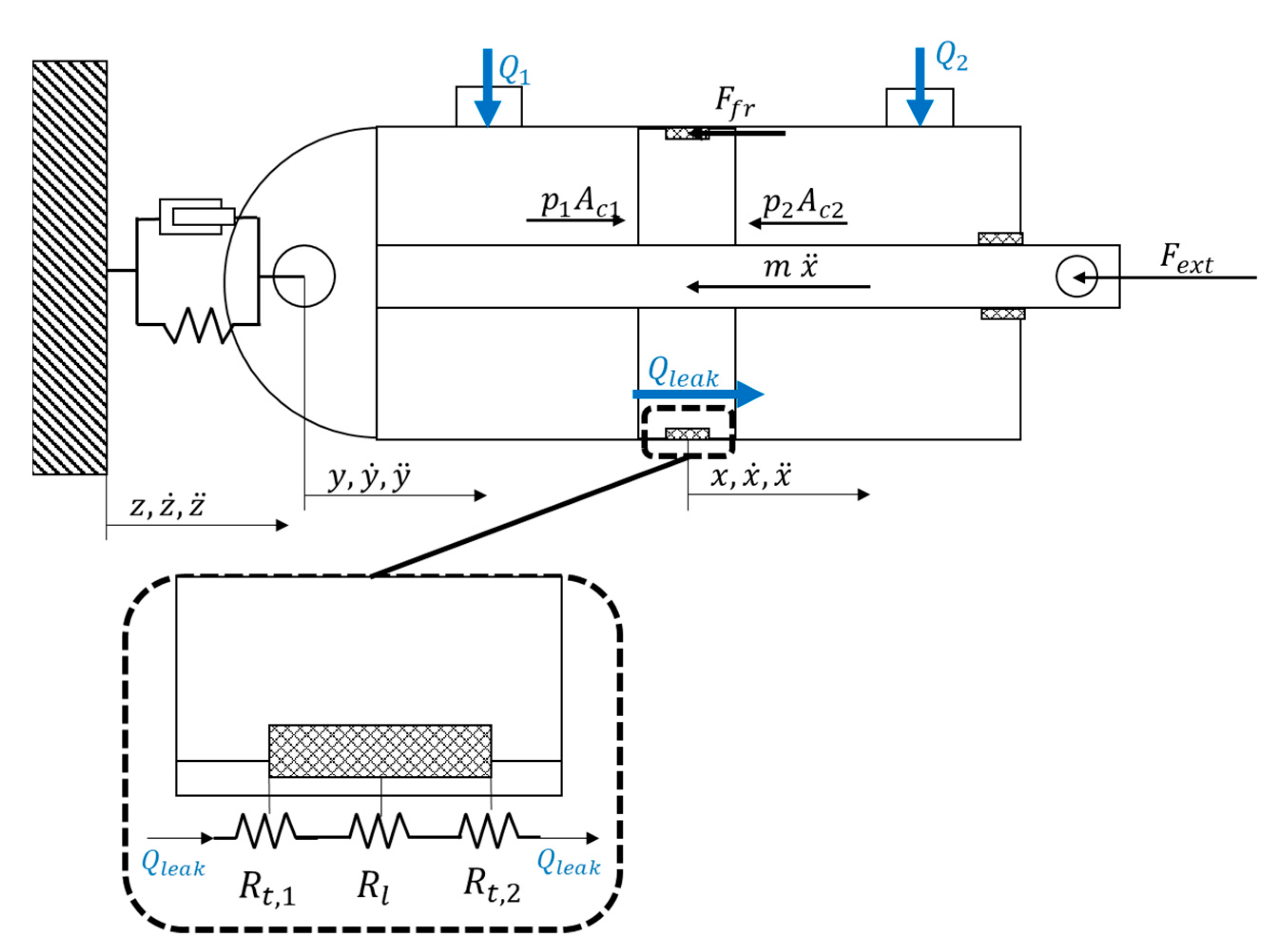
3.1. Simulation Model
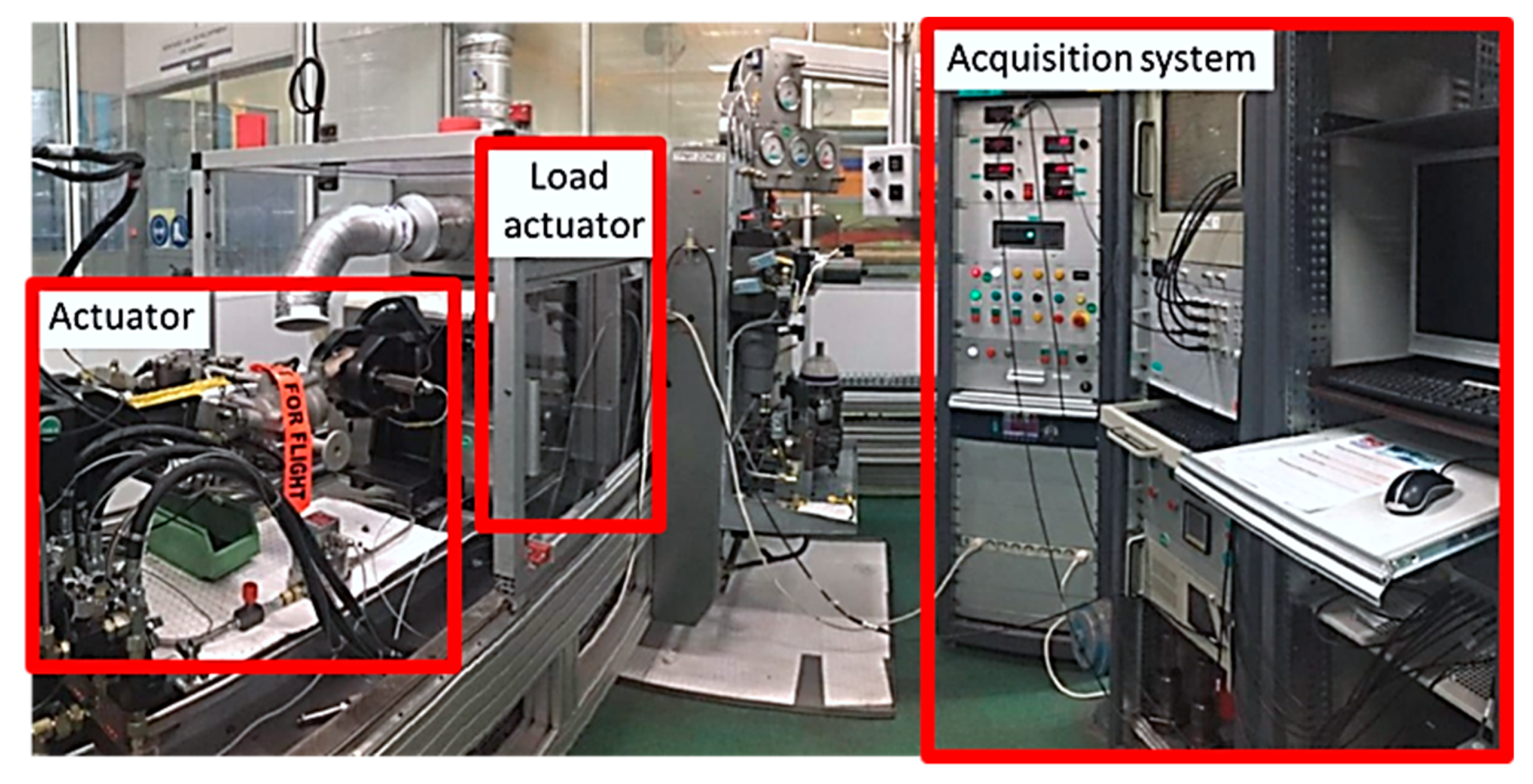
3.2. Experimental Set-Up and Design of Experiment
4. Feature Selection and Preliminary Results
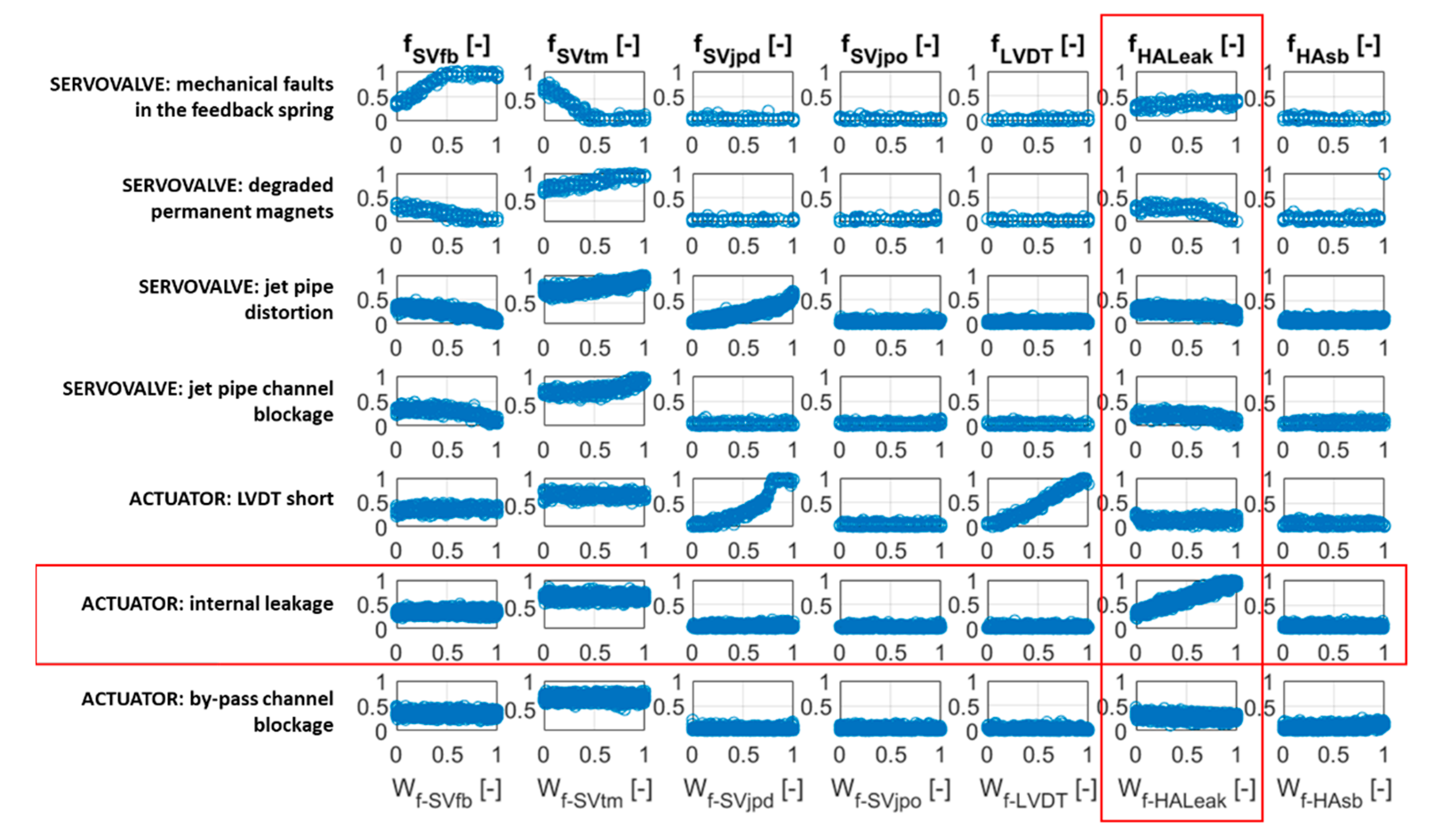
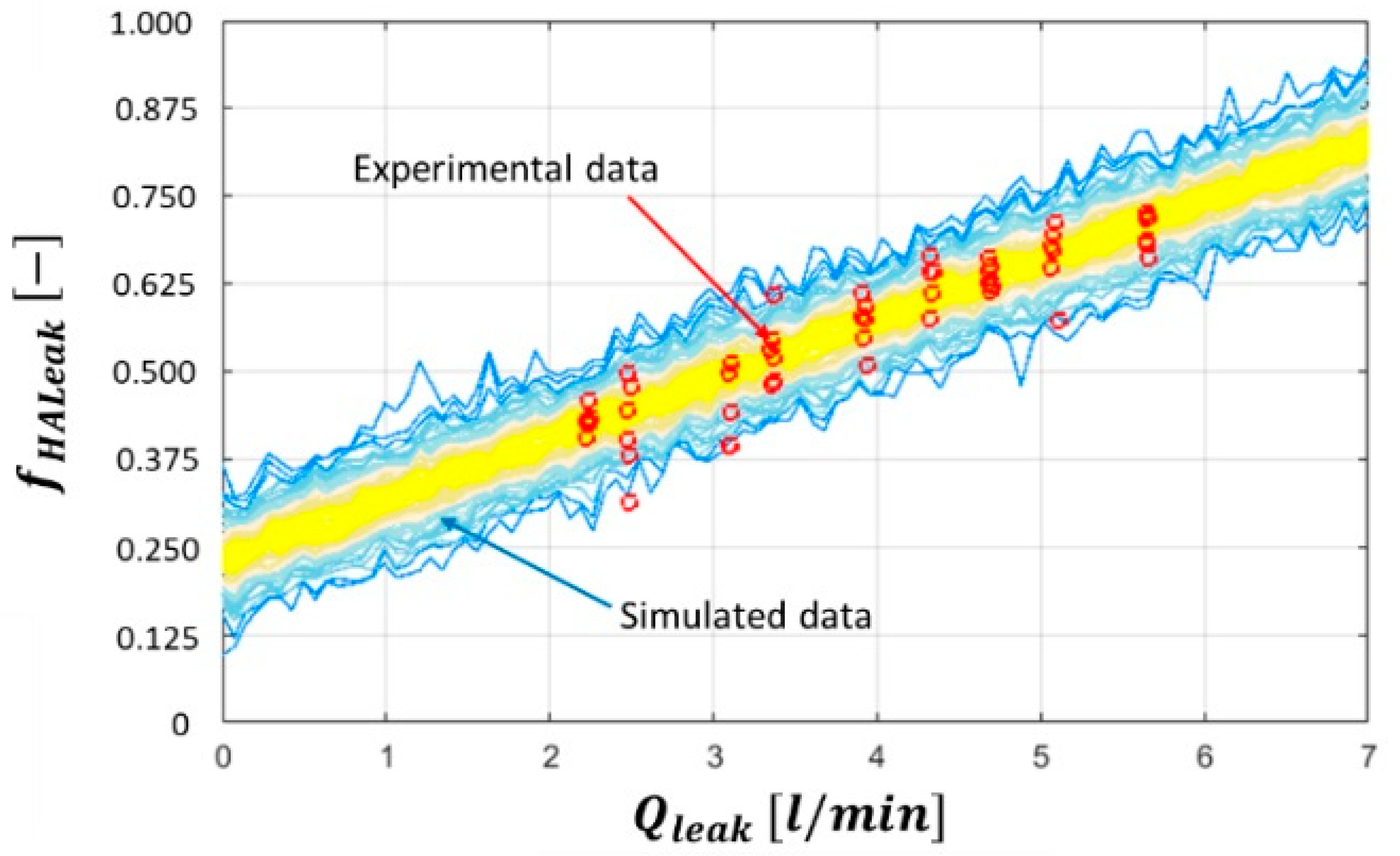
4.1. Results of the Simulation Campaigns
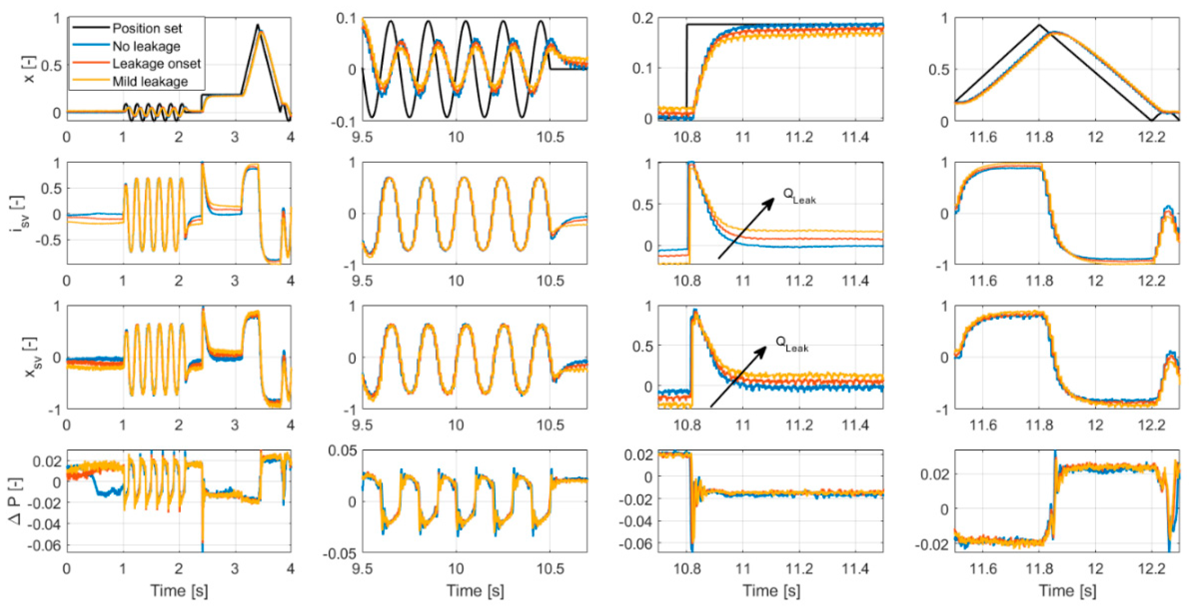
4.2. Experimental Activities
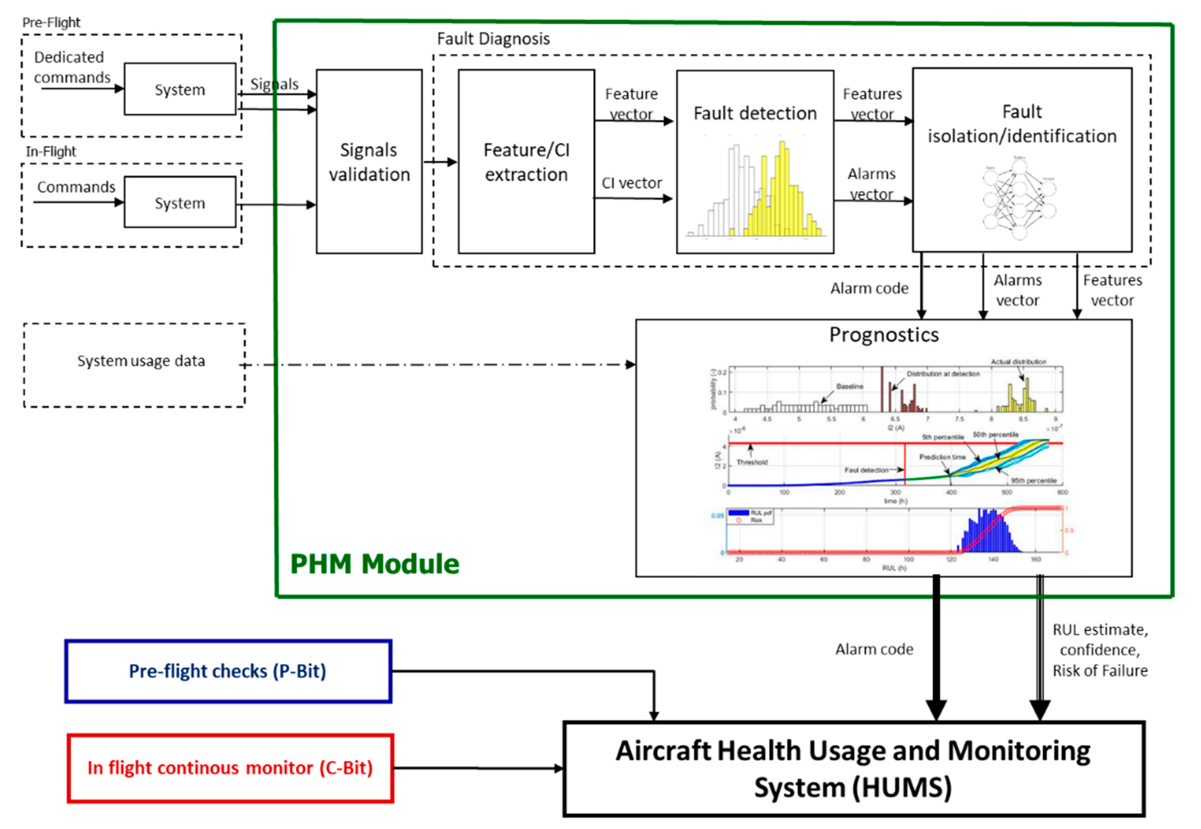
5. The PHM Algorithm
5.1. Fault Diagnosis
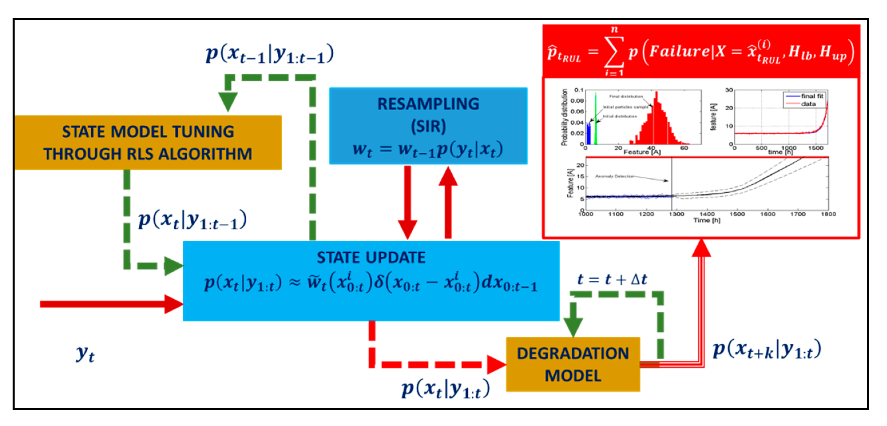
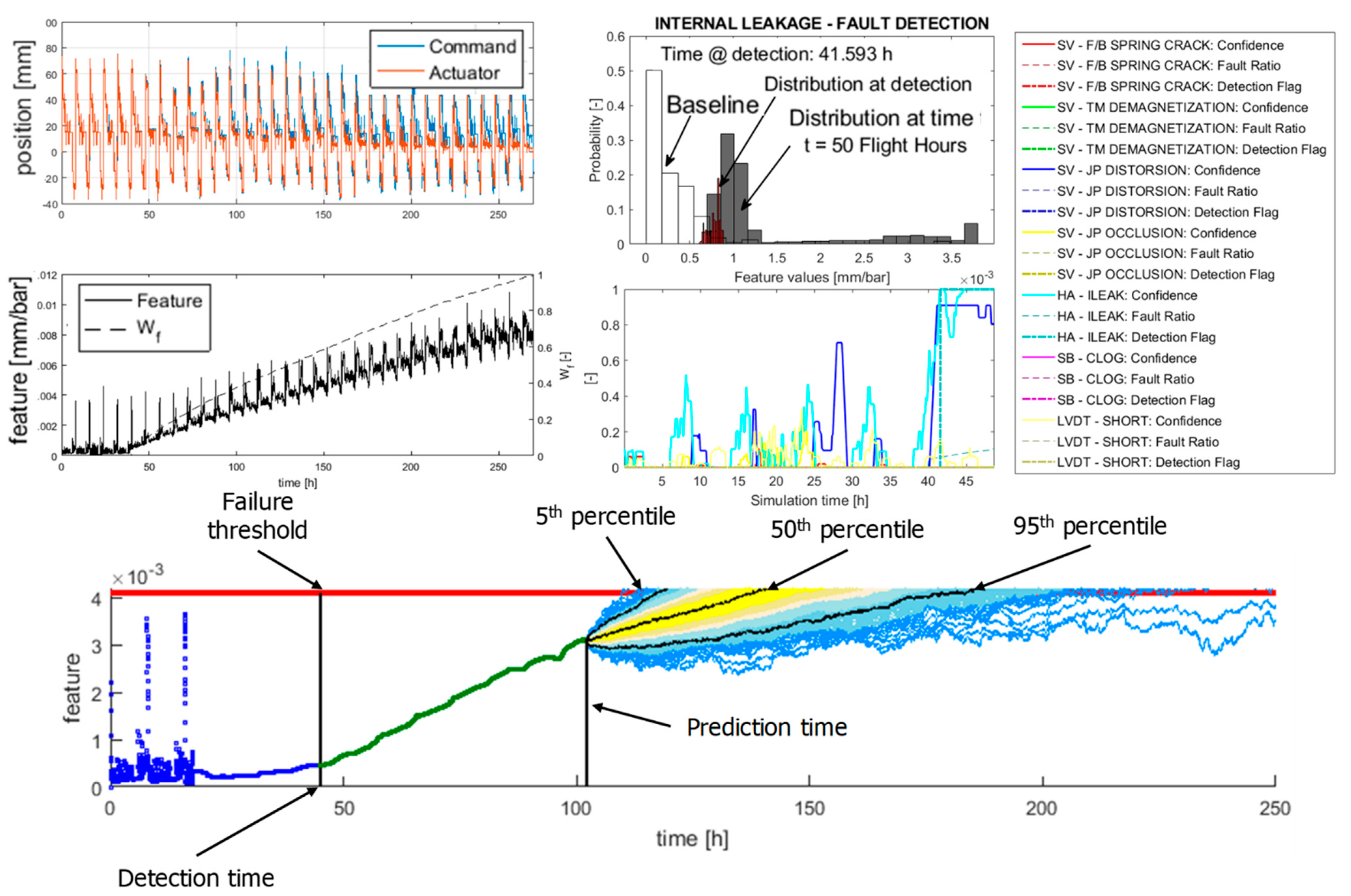
5.2. Failure Prognosis
5.3. Performance Evaluation
6. Conclusions
Author Contributions
Funding
Data Availability Statement
Acknowledgments
Conflicts of Interest
Appendix A

| Acronym | Meaning |
|---|---|
| ANN | Artificial Neural Network |
| C-BIT | Continuous Built-In Test |
| CRA | Cumulative Relative Accuracy |
| EHSA | Electro-Hydraulic Servo Actuator |
| FMECA | Failure Mode, Effects, and Criticality Analysis |
| I-BIT | Interruptive Built-In Test |
| LVDT | Linear Variable Differential Transducer |
| P-BIT | Preflight Built-In Test |
| PHM | Prognostics and Health Management |
| RA | Relative Accuracy |
| RUL | Remaining Useful Life |
| SVM | Support Vector Machine |
References
- International Air Transport Association (IATA). Airline Maintenance Cost Executive Commentary an Exclusive Benchmark Analysis (FY2009 Data) by IATA’s Maintenance Cost Task Force. 2011. Available online: https://www.dea.univr.it/documenti/Avviso/all/all698615.pdf (accessed on 29 July 2021).
- Marla, L.; Vaaben, B.; Barnhart, C. Integrated Disruption Management and Flight Planning to Trade Off Delays and Fuel Burn. Transport. Sci. 2017, 51, 88–111. [Google Scholar] [CrossRef] [Green Version]
- Brown, D.W.; Georgoulas, G.; Bole, B.M. Prognostics Enhanced Reconfigurable Control of Electro-Mechanical Actuators. In Proceedings of the Annual Conference of the Prognostics and Health Management Society, San Diego, CA, USA, 27 September–1 October 2009. [Google Scholar]
- Bertolino, A.C.; Jacazio, G.; Mauro, S.; Sorli, M. Investigation on the ball screws no-load drag torque in presence of lubrication through MBD simulations. Mech. Mach. Theory 2021, 161, 104328. [Google Scholar] [CrossRef]
- Byington, C.S.; Watson, M.; Edwards, D. Data-driven neural network methodology to remaining life predictions for aircraft actuator components. IEEE Aerosp. Conf. Proc. 2004, 6, 3581–3589. [Google Scholar] [CrossRef]
- Guo, R.; Sui, J. Remaining Useful Life Prognostics for the Electro-Hydraulic Servo Actuator Using Hellinger Distance-Based Particle Filter. IEEE Trans. Instrum. Meas. 2019, 69, 1148–1158. [Google Scholar] [CrossRef]
- Chen, Y.; Mo, Z.; Xie, L.; Miao, Q. Fault Detection and Diagnosis of Aircraft Electro Hydrostatic Actuator Control System. In Proceedings of the 2018 Prognostics and System Health Management Conference, Chongqing, China, 26–28 October 2019. [Google Scholar]
- Li, L.; Huang, Y.; Tao, J.; Liu, C.; Li, K. Featured temporal segmentation method and AdaBoost-BP detector for internal leakage evaluation of a hydraulic cylinder. Meas. J. Int. Meas. Confed. 2018, 130, 279–289. [Google Scholar] [CrossRef]
- Autin, S.; Socheleau, J.; Dellacasa, A.; De Martin, A.; Jacazio, G.; Vachtsevanos, G. Feasibility Study of a PHM System for Electro-hydraulic Servo- actuators for Primary Flight Controls. In Proceedings of the Annual Conference of the Prognostic and Health Management Society, Philadelphia, PA, USA, 24–27 September 2018; pp. 1–19. [Google Scholar]
- Autin, S.; De Martin, A.; Jacazio, G.; Socheleau, J.; Vachtsevanos, G.J. Results of a feasibility study of a Prognostic System for Electro-Hydraulic Flight Control Actuators. Int. J. Progn. Heal. Manag. 2021, 12. [Google Scholar] [CrossRef]
- De Martin, A.; Jacazio, G.; Nesci, A.; Sorli, M. In-depth Feature Selection for PHM System’s Feasibility Study for Helicopters’ Main and Tail Rotor Actuators. In Proceedings of the European Conference of the Prognostics and Health Management Society, PHME2020. Turin, Italy, 27–31 July 2020; pp. 1–9. [Google Scholar]
- Nesci, A.; De Martin, A.; Jacazio, G.; Sorli, M. Detection and Prognosis of Propagating Faults in Flight Control Actuators for Helicopters. Aerospace 2020, 7, 20. [Google Scholar] [CrossRef] [Green Version]
- Vachtsevanos, G.; Lewis, F.; Roemer, M.; Hess, A.; Wu, B. Intelligent Fault Diagnosis and Prognosis for Engineering Systems; John Wiley & Sons, Inc.: Hoboken, NJ, USA, 2006; ISBN 9780470117842. [Google Scholar]
- De Martin, A.; Dellacasa, A.; Jacazio, G.; Sorli, M. High-Fidelity Model of Electro-Hydraulic Actuators for Primary Flight Control Systems. In Proceedings of the BATH/ASME 2018 Symposium on Fluid Power and Motion Control, Bath, UK, 12–14 September 2018. [Google Scholar]
- Urata, E. On the torque generated in a servo valve torque motor using permanent magnets. Proc. Inst. Mech. Eng. Part C J. Mech. Eng. Sci. 2007, 221, 519–525. [Google Scholar] [CrossRef]
- Urata, E. Influence of unequal air-gap thickness in servo valve torque motors. Proc. Inst. Mech. Eng. Part C J. Mech. Eng. Sci. 2007, 221, 1287–1297. [Google Scholar] [CrossRef]
- Urata, E.; Suzuki, K. Stiffness of the elastic system in a servo-valve torque motor. Proc. Inst. Mech. Eng. Part C J. Mech. Eng. Sci. 2011, 225, 1963–1972. [Google Scholar] [CrossRef]
- Bertolino, A.C.; Gentile, R.; Jacazio, G.; Marino, F.; Sorli, M. EHSA primary flight controls seals wear degradation model. In Proceedings of the ASME International Mechanical Engineering Congress and Exposition, Proceedings (IMECE), Pittsburgh, PA, USA, 9–15 November 2018. [Google Scholar]
- Jelali, M.; Kroll, A. Hydraulic Servo-Systems; Springer: Berlin/Heidelberg, Germany, 2003; ISBN 978-1-4471-1123-8. [Google Scholar]
- Jacazio, G.; De Martin, A. Influence of rotor profile geometry on the performance of an original low-pressure gerotor pump. Mech. Mach. Theory 2016, 100, 296–312. [Google Scholar] [CrossRef]
- Stachowiak, G.W.; Batchelor, A.W. Engineering Tribology, 4th ed.; Elsevier: Amsterdam, The Netherlands, 2014; ISBN 9780123970473. [Google Scholar]
- ARCHARD, J. Basic lubrication theory A. Cameron Longmans. In Tribology; Longman: London, UK, 1971. [Google Scholar] [CrossRef]
- Jacobson, M.Z. Fundamentals of Atmospheric Modeling, 2nd ed.; Cambridge University Press: Cambridge, UK, 2005; ISBN 9781139165389. [Google Scholar]
- De Martin, A.; Jacazio, G.; Vachtsevanos, G. Windings fault detection and prognosis in electro-mechanical flight control actuators operating in active-active configuration. Int. J. Progn. Heal. Manag. 2017, 8. [Google Scholar] [CrossRef]
- Orchard, M.E.; Vachtsevanos, G.J. A particle-filtering approach for on-line fault diagnosis and failure prognosis. Trans. Inst. Meas. Control 2009, 31, 221–246. [Google Scholar] [CrossRef]
- Roemer, M.J.; Byington, C.S.; Kacprzynski, G.J.; Vachtsevanos, G.; Goebel, K. Prognostics. In System Health Management: With Aerospace Applications; John Wiley & Sons: Hoboken, NJ, USA, 2011; ISBN 9780470741337. [Google Scholar]
- Arulampalam, M.S.; Maskell, S.; Gordon, N.; Clapp, T. A tutorial on particle filters for online nonlinear/nongaussian bayesian tracking. In Bayesian Bounds for Parameter Estimation and Nonlinear Filtering/Tracking; IEEE: New York, NY, USA, 2007; ISBN 9780470544198. [Google Scholar]
- Acuña, D.E.; Orchard, M.E. Particle-filtering-based failure prognosis via sigma-points: Application to Lithium-Ion battery State-of-Charge monitoring. Mech. Syst. Signal Process. 2017, 85, 827–848. [Google Scholar] [CrossRef]
- Acuña, D.E.; Orchard, M.E. A theoretically rigorous approach to failure prognosis. In Proceedings of the 10th Annual Conference of the Prognostics and Health Management Society 2018 (PHM18), Philadelphia, PA, USA, 24–27 September 2018. [Google Scholar]
- Bishop, C.M. Pattern Recoginiton and Machine Learning; Springer: Berlin, Germany, 2006; ISBN 978-0-387-31073-2. [Google Scholar]
- Grosso, L.A.; De Martin, A.; Jacazio, G.; Sorli, M. Development of data-driven PHM solutions for robot hemming in automotive production lines. Int. J. Progn. Heal. Manag. 2020, 11. [Google Scholar] [CrossRef]
- De Martin, A.; Jacazio, G.; Sorli, M. Enhanced Particle Filter framework for improved prognosis of electro-mechanical flight controls actuators. In Proceedings of the PHM Society European Conference, Utrecht, The Netherlands, 3–6 July 2018; Volume 4. [Google Scholar]
- Saxena, A.; Celaya, J.; Balaban, E.; Goebel, K.; Saha, B.; Saha, S.; Schwabacher, M. Metrics for evaluating performance of prognostic techniques. In Proceedings of the 2008 International Conference on Prognostics and Health Management, PHM 2008, Denver, CO, USA, 6–9 October 2008. [Google Scholar]


| Failure Mode | Symbol | Feature |
|---|---|---|
| Mechanical faults in the feedback spring of the servovalve | ||
| Degraded permanent magnets in the first stage of the servovalve | ||
| Jet pipe distortion | ||
| Jet pipe channel blockage | ||
| Short between LVDT windings | ||
| Internal leakage within the EHSA | ||
| Blockage of the by-pass channel in the stand-by actuator |
Publisher’s Note: MDPI stays neutral with regard to jurisdictional claims in published maps and institutional affiliations. |
© 2021 by the authors. Licensee MDPI, Basel, Switzerland. This article is an open access article distributed under the terms and conditions of the Creative Commons Attribution (CC BY) license (https://creativecommons.org/licenses/by/4.0/).
Share and Cite
Bertolino, A.C.; De Martin, A.; Jacazio, G.; Sorli, M. A Case Study on the Detection and Prognosis of Internal Leakages in Electro-Hydraulic Flight Control Actuators. Actuators 2021, 10, 215. https://0-doi-org.brum.beds.ac.uk/10.3390/act10090215
Bertolino AC, De Martin A, Jacazio G, Sorli M. A Case Study on the Detection and Prognosis of Internal Leakages in Electro-Hydraulic Flight Control Actuators. Actuators. 2021; 10(9):215. https://0-doi-org.brum.beds.ac.uk/10.3390/act10090215
Chicago/Turabian StyleBertolino, Antonio Carlo, Andrea De Martin, Giovanni Jacazio, and Massimo Sorli. 2021. "A Case Study on the Detection and Prognosis of Internal Leakages in Electro-Hydraulic Flight Control Actuators" Actuators 10, no. 9: 215. https://0-doi-org.brum.beds.ac.uk/10.3390/act10090215