
Topology Optimization of Large-Scale 3D Morphing Wing Structures


1
Department of Mechanical Engineering, Technical University of Denmark, 2800 Kongens Lyngby, Denmark
2
Adaptive Structures Technologies, The Italian Aerospace Research Centre, CIRA, Via Maiorise, 81043 Capua, Italy
*
Author to whom correspondence should be addressed.
Actuators 2021, 10(9), 217; https://0-doi-org.brum.beds.ac.uk/10.3390/act10090217
Submission received: 1 July 2021
/
Revised: 24 August 2021
/
Accepted: 26 August 2021
/
Published: 31 August 2021
(This article belongs to the Special Issue Aerospace Mechanisms and Actuation)
Abstract
:This work proposes a systematic topology optimization approach for simultaneously designing the morphing functionality and actuation in three-dimensional wing structures. The actuation was modeled by a linear-strain-based expansion in the actuation material. A three-phase material model was employed to represent structural and actuating materials and voids. To ensure both structural stiffness with respect to aerodynamic loading and morphing capabilities, the optimization problem was formulated to minimize structural compliance, while the morphing functionality was enforced by constraining a morphing error between the actual and target wing shape. Moreover, a feature-mapping approach was utilized to constrain and simplify the actuator geometries. A trailing edge wing section was designed to validate the proposed optimization approach. Numerical results demonstrated that three-dimensional optimized wing sections utilize a more advanced structural layout to enhance structural performance while keeping the morphing functionality better than two-dimensional wing ribs. The work presents the first step towards the systematic design of three-dimensional morphing wing sections.
1. Introduction
Since the earliest forms of aviation, efforts have been made to minimize drag resulting from discontinuous flight control surfaces. The Wright brothers solved roll control using a wing-warping mechanism in their first flying machine. Other remarkable historical examples are Holle’s adaptive systems for modifying leading and trailing edges [1] and Parker’s variable camber wing [2] used to increase cruising speed by continuously varying the geometrical wing characteristics by means of a proper arrangement of the internal structure.
Since that time, the idea of creating motion using flexible structures became unreasonable from the viewpoint of engineering design since engineering practice gradually tried to avoid flexibility, and many systems were designed to be rigid. Traditional metals, such as aluminum, stainless steel, and titanium, dominated the aerospace industry for over fifty years, as they were considered lightweight, inexpensive, and state-of-the-art. Meanwhile, the interest in cost-effective fuel-efficient aircraft technologies increased gradually, and metals started ceding territory to new alloys and composite materials designed to offer lighter weight, greater strength, better corrosion resistance, and reduced assembly and manufacturing costs. Once only considered for noncritical interior cabin components, composite materials are now occupying the space of traditional materials for a wide range of aircraft components, including wing, fuselage, landing gear, and engine.
However, a variation of this trend exists even in modern commercial aircraft, as the use of metallic structures has not entirely disappeared. Aircraft mechanisms, predominantly made from metallic components, continue to be developed and improved to offer ever-increasing performance and more effective deployment kinematics. Metallic mechanisms are still used for both the primary and secondary control surfaces and for landing gear deployment and stowage.
However, the design templates of such traditional wings, conceived of rigid structures with discrete control surfaces operated by rigid-body mechanisms, are a century old. They provide the current standard of adaptive wing airfoils, necessary to efficiently meet the stringent aircraft aerodynamic requirements, involving both high-speed efficiency in cruise and high-lift performance in takeoff and landing conditions. However, they do no justice to what nature has achieved in birds; in flight, they are capable of actively morphing their wings accordingly to produce sufficient lift and thrust and control and stabilize their flight.
The simultaneous push for enhanced aircraft flight performance, control authority, and multimission capability and the advent of one-piece designs, reducing the number of components in the overall assemblies, have motivated investigations into conformal morphing systems. In this study, a continuous-span morphing wing trailing edge is considered, with the goal of increasing aircraft aerodynamic efficiency and reducing assembly time and costs. We define a morphing wing device as a structural system with a continuous skin and an internal mechanism capable of achieving morphing of the outer skin.
With the continuous drive to decrease weight, topology optimization [3,4] has been used to design lightweight and adaptive compliant mechanisms [5]. Furthermore, mechanism design is often a complex task based on experience and trial and error approaches. Sigmund [6] proposed using topology optimization in the systematic design of mechanisms, both on a micro and a macro scale. The systematic design of mechanisms is obtained by optimizing a domain to generate a specific shape. Sigmund [7,8] also extended mechanism design to multiphysical and multimaterial models by modeling bimaterial electrothermomechanical actuators using topology optimization.
Studies of the topology optimization of morphing wing mechanisms are limited to two-dimensional (2D) models. Kambayashi et al. [9] presented a method for obtaining a multilayered compliant mechanism for a morphing wing under multiple flight conditions. Tong et al. [10] studied the topology optimization of a composite material integrated into a compliant mechanism for a morphing trailing edge. Zhang et al. [11] presented a study of a morphing wing leading edge driven by a compliant mechanism design. De Gaspari et al. [12] proposed the design of an adaptive compliant wing through a multilevel optimization approach where, sizing, shape, and topology optimization were adopted. Gomes and Palacios [13] presented a method for a two-step optimization of aerodynamic shape adaptation by a compliant mechanism, through modeling fluid–structure interaction problems combined with density-based topology optimization. Gu et al. [14] presented a method for finding an optimized structural layout of a morphing wing and simultaneously finding the layout of a driving actuator, by modeling a shape memory alloy (SMA) wire.
All of the above studies only addressed the mechanism as a 2D structure, but as the kinematics of a morphing structure is not necessarily restricted to 2D, the results might be inferior. Furthermore, a 2D study limits the potential solution space for optimization and does not give much insight, except as an academic example. Hence, it is postulated that a superior mechanism design can be obtained if the problem is posed in three-dimensional (3D) space.
The majority of the mechanisms presented in the above studies were driven by an external force or displacement, meaning that in practice, additional space is required for an actuator (or actuators) in the morphing structure, as investigated in [15]. Actuating, as part of the mechanism, could prove a better overall volume optimum for a morphing wing, as seen in [14]. Therefore, this paper proposes a novel approach for simultaneously designing the mechanism and actuator for 3D morphing structures via the topology optimization method. A three-phase material interpolation scheme was employed to represent structural and actuating materials as well as voids in the optimization procedure. In order to run the 3D topology optimization method efficiently, a parallel framework was utilized.
The paper is organized as follows: Section 2 introduces the modeling of a morphing wing structure, with a brief description of the finite element formulation. Section 3 presents the proposed topology optimization methodology. Section 4 shows optimized morphing wing structures for different design domain formulations. Section 5 and Section 6 provide a discussion and conclusions.
2. Optimization Model
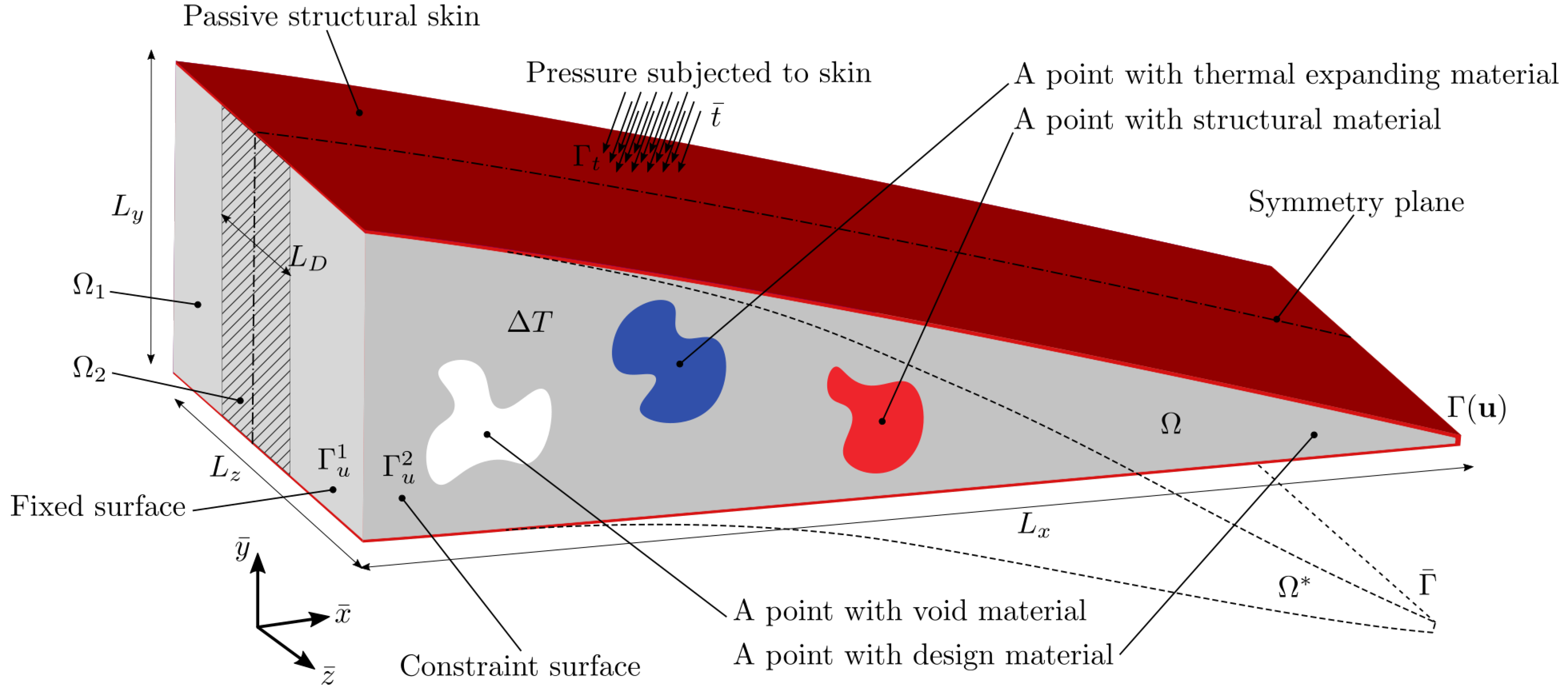
The optimization problem concerns the composition of the void, structural, and actuating material in the design domain for a trailing edge wing model, such that the surface (function of the state field, ) of the trailing edge will deform to a target surface in the morphed domain . Simultaneously stored strain energy from a surface traction must be minimized for stiffness maximization. The actuation is assumed to be a linear-strain-based expansion in the actuating material, stimulated by a thermal change . This may also be interpreted as a simple linear model of an SMA-based actuator. A more advanced or nonlinear actuation model could also be included, but would require nonlinear analysis, not considered in this first work. The problem is illustrated in Figure 1. Some areas of may be restricted to be a passive material, i.e., the void, structural, or actuating materials.
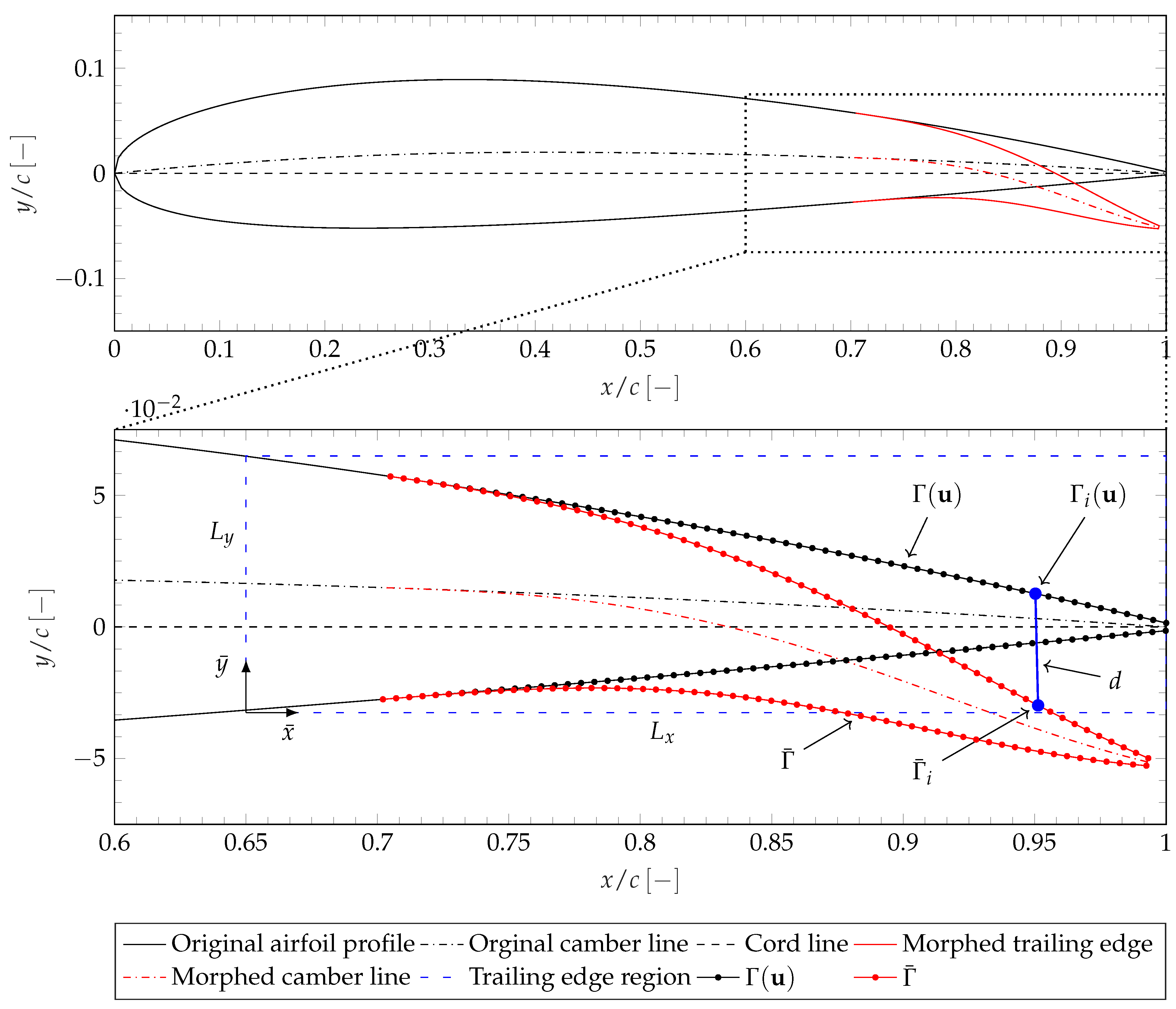
The trailing edge model was inspired by Vecchia et al. [16] and was realized as follows. An NACA 2414 airfoil was considered as a base model. The airfoil is illustrated in Figure 2. We used the software application XFOIL [17] to calculate the aerodynamic load case subjected to the airfoil in the form of pressure coefficients. The pressure was calculated based on an assumed angle of attack of , inviscid flow, and a free stream velocity of 70 at sea level. For the trailing edge, we only considered the airfoil in the range , which is highlighted as the trailing edge region in Figure 2. c = 1400 was the cord. The trailing edge region had the reference coordinate system and the dimension .
The target morphing shape was obtained by rotating the camber line gradually with morphing angle , with being the tip morphing angle. The rotation was with respect to the cord line, such that the beginning and end of the target morphing shape experienced little bending, illustrated in Figure 2.
The 2D airfoil profile, pressure model, and target morphing shape were extruded in the out-of-plane direction with , so a wing section was formed, as seen in Figure 1. The internal part of the trailing edge section (i.e., the design domain) was divided into two sections, where the middle section had the width so that the design domain could be segmented into the subdesign domains, (light gray) and (hatched); see Figure 1. In the following problems, was used. The design domain of the trailing edge section was enclosed by a skin (passive domain) with a thickness of . The trailing edge section was modeled with the symmetry -plane at ; the surface was fixed, and the surface was constrained with no -displacement (symmetry).
The chosen material properties are listed in Table 1. The structural and actuating materials are represented by Subscripts 1 and 2, respectively. The skin had the same material properties as the structural material in this academic study, but could without problems be substituted with a more compliant material. The thermal change was set to unity.
The governing equation for the above problem was given in the standard finite element formulation considering two load cases,
with , , and denoting the global-stiffness matrix and displacement and force vectors, respectively. The domain was discretized by nonregular 8-node trilinear hexahedral isoparametric elements. was assembled from element stiffness matrices, . For more details on finite element analysis, the reader is referred to [18]. We define the two load cases as:
where the subscripts “ext” and “int” denote external and internal loading, respectively. The external loading was defined as the aerodynamic loading on surface . The internal loading was defined as the linear-strain-based actuator expansion, modeled as the linear element-volume expansion force. It depends on the element constitutive law, , the element thermal expansion coefficient , and the temperature change ,
where denotes the elemental strain–displacement matrix.
3. Topology Optimization
3.1. Optimization Problem
The design problem for a morphing wing structure is sketched in Figure 1, while an illustration of the target shape is highlighted in Figure 2, as the 2D profile. As stated in the previous section, the morphing functionality was realized by constraining the error between and , where and are composed of N degrees of freedom (dof) representing the real and target morphing shapes, respectively. The error was calculated based on the nodal displacement. In Figure 2, an example is shown for target point i (shown in solid blue), where the distance d is the nodal displacement change between the original nodal point and morphed target nodal point.
In this work, we used two methods to parameterize the multiple material distribution in the design domain, i.e., a density-based approach and a feature-mapping-based approach. Details of the design parameterizations are presented in Section 3.2. To ensure structural stiffness, we formulated the optimization problem for morphing wings as structural compliance minimization under aerodynamic loading, while the morphing functionality was enforced as a constraint, stated as,
denotes the morphing displacement error between a given target morphing and actual wing shapes, and logarithm (log) is employed to normalize the constraint. and denote the volume fractions of the structural and actuating materials, and , , and are the corresponding prescribed upper bounds.
The displacement error was formulated as the aggregation p-mean function of the relative error of N target degrees of freedom,
where was used. The volume constraints are defined in the following Section 3.2, where two design parameterizations are introduced.
3.2. Density Parameterizations and Interpolation Functions
Two different design parameterizations were employed in this study, i.e., a density-based approach and a feature-mapping-based approach. In both cases, two elementwise density fields were used to indicate the material occupations.
In order to avoid mesh dependency and checkerboard patterns [19,20] and enhance the discreteness of the designs, we employed a three-field approach as formulated by [21]. An elementwise density field was first filtered, , using the modified Helmholtz-equation-type PDE filter [22], stated as:
where and is the physical filter radius. A physical density field was then obtained by a modified smooth Heaviside function:
Here, controls the steepness/sharpness of the function and sets the threshold value.
3.2.1. Density Approach
In the density-based approach, denoted density approach, we introduced two design variables per element to parameterize the material distributions, i.e., a materiel density design variable and a material phase design variable with . Hence, the design variables and two density fields are:
In this approach, and indicate the element is occupied by the actuating material, and by the structural material, and by the void. Hence, the volume fractions of the structural and actuating materials are calculated by:
where is the element volume and V the total volume of .
We employed the three-phase material model proposed by Sigmund [8] to interpolate the elemental material properties, given as:
with the phase interpolations defined as:
Here, and are the lower and upper Hashin–Shtrikman–Walpole (HSW) bounds on the shear modulus, and and are the lower and upper Hashin–Shtrikman (HS) bounds on the bulk modulus. Details of the bound formulation were shown in the Appendix of [8]. interpolates linearly between the lower and upper bounds and works as a penalization mechanism for intermediate densities. is found from (11) by setting . The interpolation of the linear-strain-based expansion is important as it scales correctly with the material stiffness and hence stays monotonic.
3.2.2. Feature Mapping Approach
Density-based topology optimization often results in rather complex, distributed, and very “natural”-looking structures. A simpler geometry representation of the actuating material regions is highly desired from a manufacturing point of view. To impose this while still representing the design domain on a fixed grid, a feature-mapping-based approach was adopted.
Feature mapping is a broad term that defines the general method for representing or mapping high-level geometric feature parameterization on a fixed nonconforming grid. The first use of feature mapping was demonstrated by Norato et al. [23]. The reader is referred to the comprehensive review by Wein et al. [24] on feature mapping, for more details.
In this study, geometric features were implicitly represented using a feature-mapped density field, . We used a superellipsoid to describe the actuator (similar to Wang [25]), where the center of the superellipsoid is located with . For a given element located at , the relation between the element and the superellipsoid is represented by:
Here, indicates that the element is inside of the superellipsoid, and on the boundary, for outside. are the transformed translational coordinates, defined by:
is a general rotation matrix controlled by the two rotation angles, and , and r and l are the semidiameters. The exponents and define the feature approximation of the superellipsoid. For and , the superellipsoid will become a cylinder. We used and .
The design vector, , of the superellipsoid is:
The individual design variables in were normalized for the optimization problem; here, we scaled the angles by .
The feature-mapped density field was generated using a smoothed Heaviside function,
where controls the steepness/sharpness of the function, as the projection filter [21]. With the feature-mapped density field, the design domain was now controlled by the elementwise density design variable, , and the feature parameters, ; this formulation is referred to as the feature-mapping approach.
In this approach, the design vector, , and two density fields are:
Here, indicates the element is occupied by the actuating material, and by the structural material, and and by the void. Hence, the volume fractions of the structural and actuating materials are calculated by:
The material property interpolation in (10) and (11) must be modified for the feature-mapping approach. We propose to extend (10) and (11) for a strict geometric feature representation as:
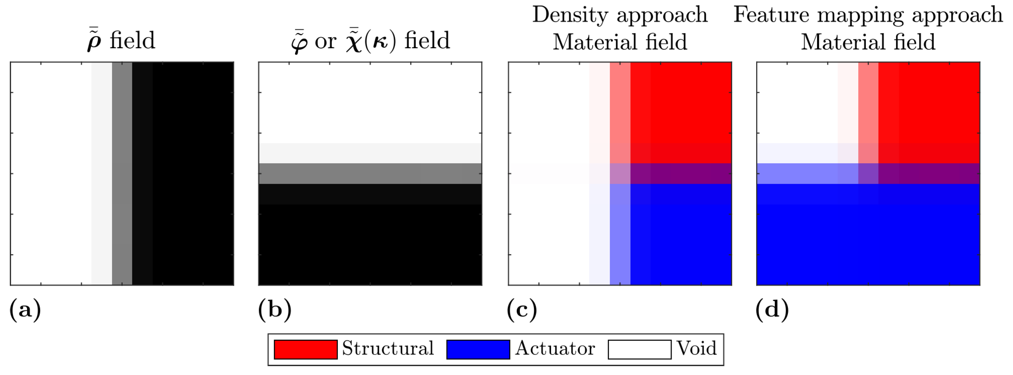
The thermal expansion coefficient interpolation was the same as for the density approach: (12). An illustration of the two parameterization approaches is seen in Figure 3, where it is seen how the two design fields are realized and how they are combined for the physical material field. Notice for the feature-mapping approach how the feature-mapped density field is dominating the material density field. As is defined in Figure 3, red material is defined as a structural material, while blue material is defined as an actuating material, for any further figures of material fields.
3.3. Sensitivity Analysis
We used the adjoint method [19] to calculate the sensitivities of a function, f, which denotes either objective or constraint functions. The sensitivities of f are found though:
where is the adjoint vector obtained from:
The chain rule was applied to obtain the sensitivities of f with respect to the design variables [21]:
Similarly, for the feature-mapped density field, the chain rule was applied to find the sensitivities regarding the feature mapping design variables .
3.4. Numerical Implementation
The topology optimization problem was implemented in a parallel 3D unstructured topology optimization framework by Träff et al. [26] based on the work by Aage and Lazarov [27] utilizing the numerical library PETSc [28]. The finite element system was solved with a multigrid preconditioned Krylov method. The optimization problem was solved with the iterative optimization scheme, MMA [29].
Move limits for and were set to 0.05, while move limits for were set to 0.05 for translation and volumetric expansion of the feature and 0.002 for rotation. A continuation approach was employed for the projection parameter , updated by every 40th iteration with an upper limit of 64. For the feature-mapping approach, was fixed to 10; furthermore, the continuations approach was only started after 300 iterations. For the phase interpolation, we set for the density approach; however, as we wanted little penalization on the actuator strength in the feature-mapping approach, was chosen for that approach.
4. Examples
This section aims to demonstrate and investigate how the proposed topology optimization method may be applied to realize a large-scale 3D morphing wing structure via morphing trailing edge section design.
The trailing edge section was meshed using Cubit [30] with an approximate element size of 0.5 , resulting in approximately 70 million elements and 210 million degrees of freedom. The mesh cannot be illustrated fully here due to the small element size compared to the size of the geometry. Instead, a close-up is presented in Figure 4, where the mesh resolution is shown.
A filter radius was set on both density fields. Two-hundred sixty-four equally distributed target nodes were used to describe the morphing shape. We only prescribed the morphing displacement error in the vertical direction , as the skin was relatively stiff. The upper bound values for the volume fraction and morphing constraints are listed in Table 2.
The optimization was run in the DTU Sophia cluster with 800 cores. The density approach result was obtained after 750 iterations, while the feature-mapping approach was obtained after 1900 iterations, as the feature-mapping approach was slow to converge. Each iteration took on average 4–5 min.
In the density approach, the design domains were initialized with a constant value that satisfied the volume constraints, according to (9). In the feature-mapping approach, the actuator was initialized with the normalized design variables listed in Table 3 (based on preliminary results obtained from the density approach). The initial design is seen in Figure 5.
4.1. Density Approach
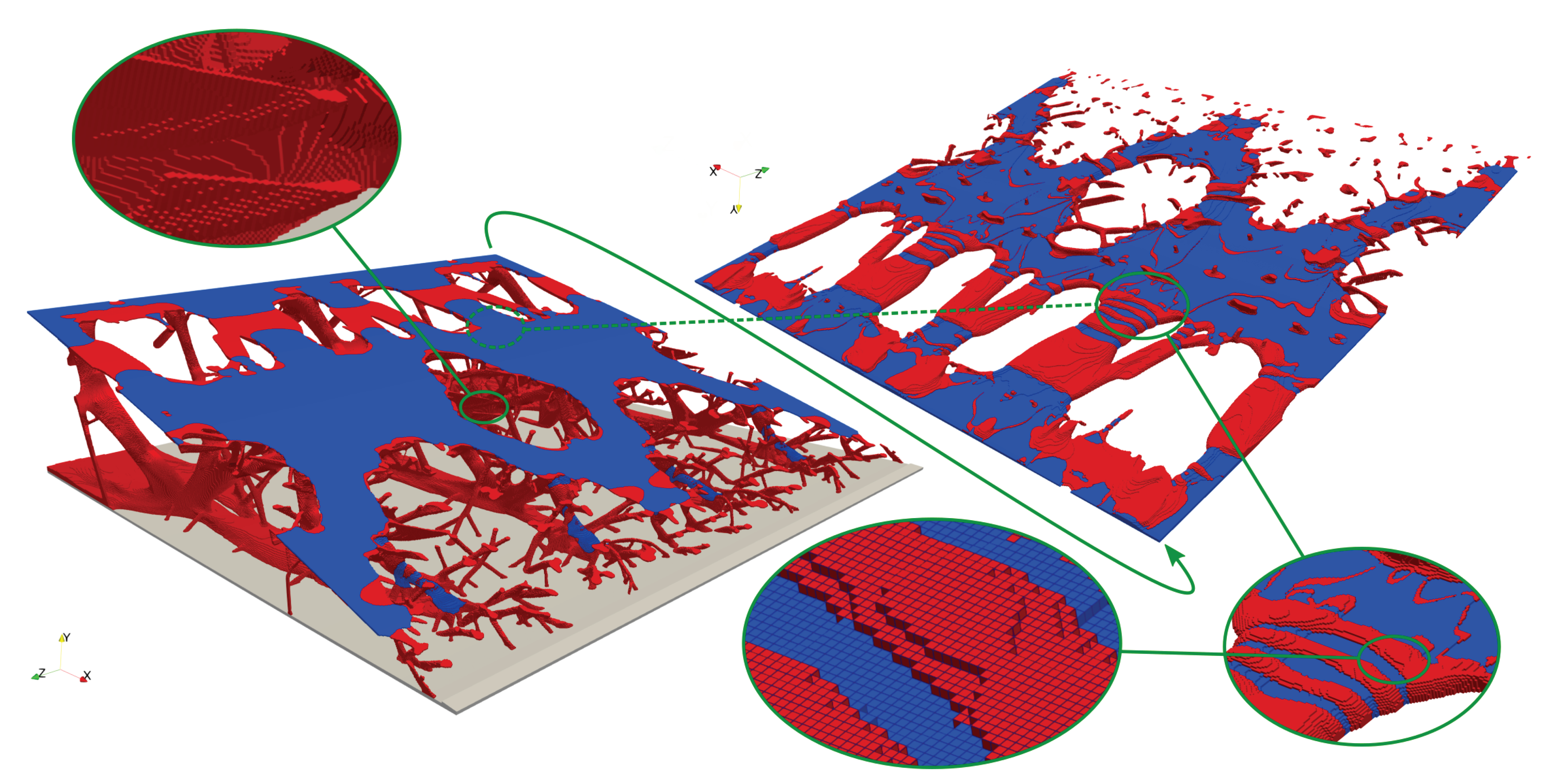
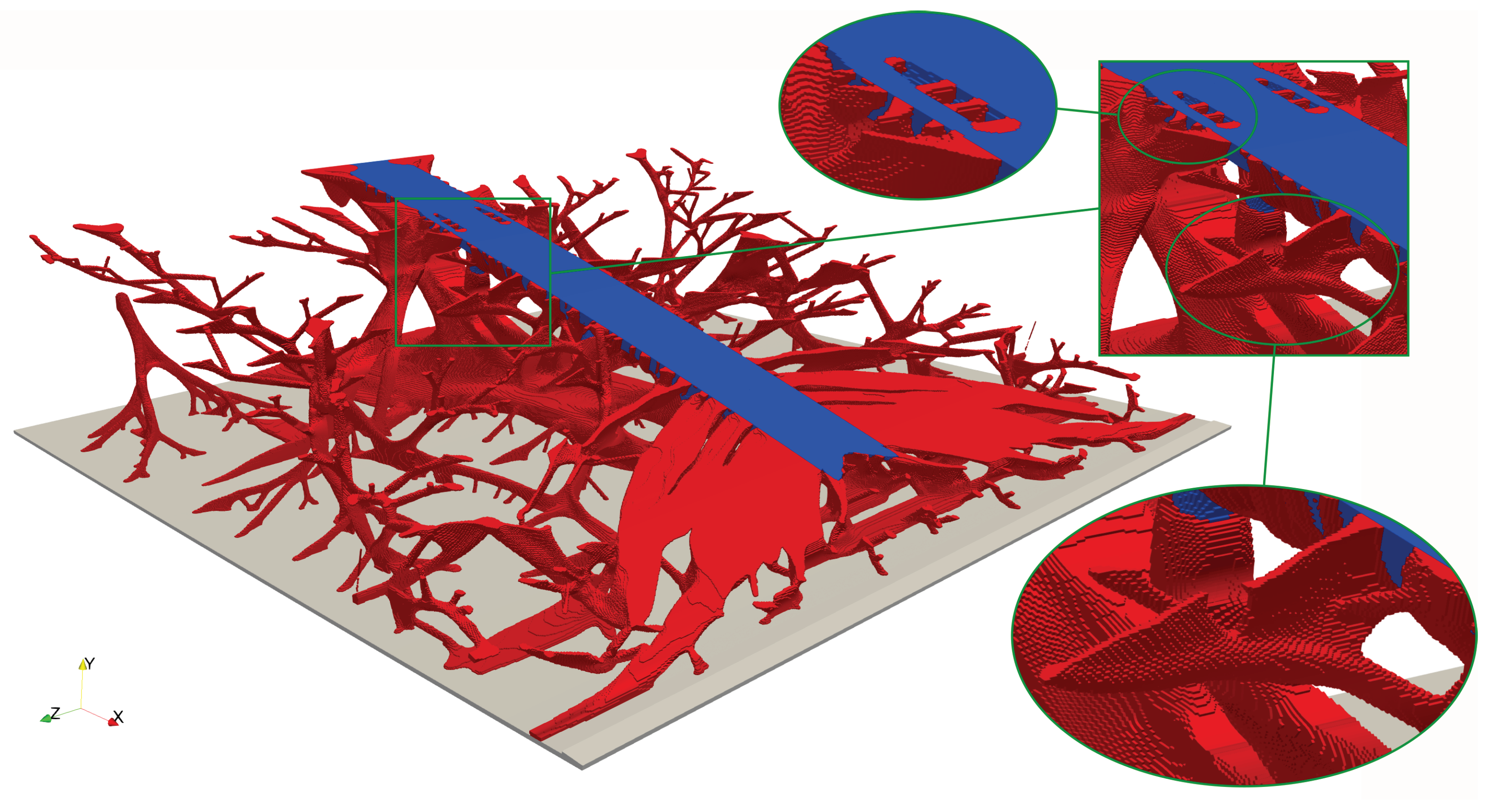
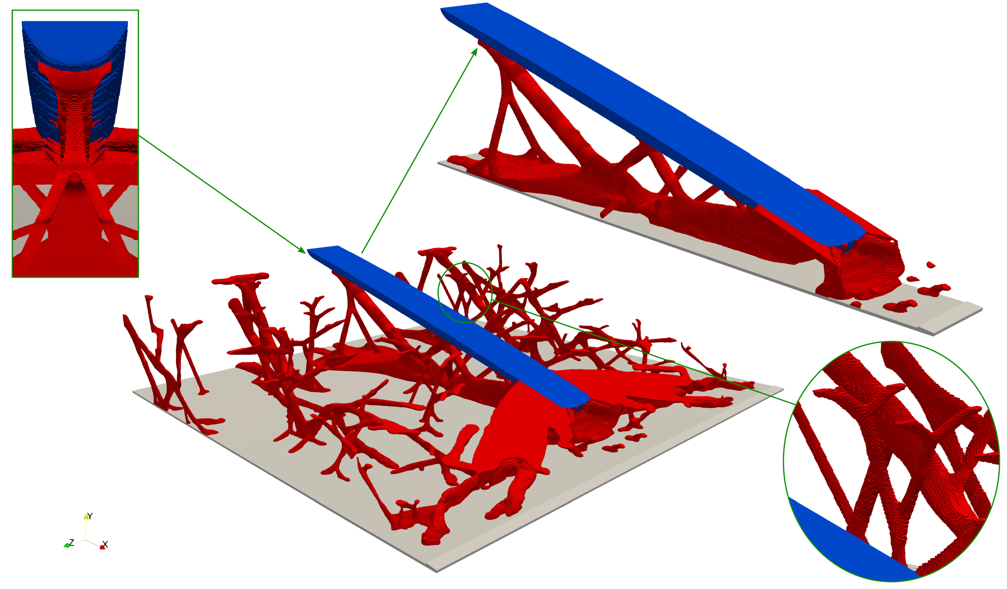
In the first result, both structural and actuating materials were freely distributed in the whole design domain, . An overview of the optimized structure is shown in Figure 4. It was seen that the structural material (red) formed a very complex structure consisting of truss and plate-like components. The truss components branched out as tree branches to connect with the skin. The structures resembled gecko feet hair structures. The features were oriented to carry the load and have the bending stiffness required to obtain the constrained morphing shape. The actuating material (blue) formed a thin plate-like structure at the top of the trailing edge to provide the maximum downwards bending moment. At the end of the trailing edge, a few truss actuators were seen. The close-up detail in Figure 4 shows that the actuating material formed a complex composite together with the structural material. The structural material formed rings around the actuating material to support the actuator, so both actuator force and stiffness were balanced; this resembled the effects of a weightlifter belt. Furthermore, a nearly periodic structure was observed, which provided a similar morphing shape along the -direction.
From a manufacturing point of view, this result is too complex to realize. To simplify the actuating region, we now only allowed the actuating material in (see Figure 1), while the structural material can be freely distributed in the whole domain. The optimized result is shown in Figure 6. Similar to the previous case, the structural material formed truss and plate-like components. Differences were observed in how the structural material formed around the actuator, i.e., the middle of the domain. We saw a stiff structure forming under the actuator and at the end of the actuator, which then branched out to provide the required mechanism to force the whole end of the trailing edge downwards.
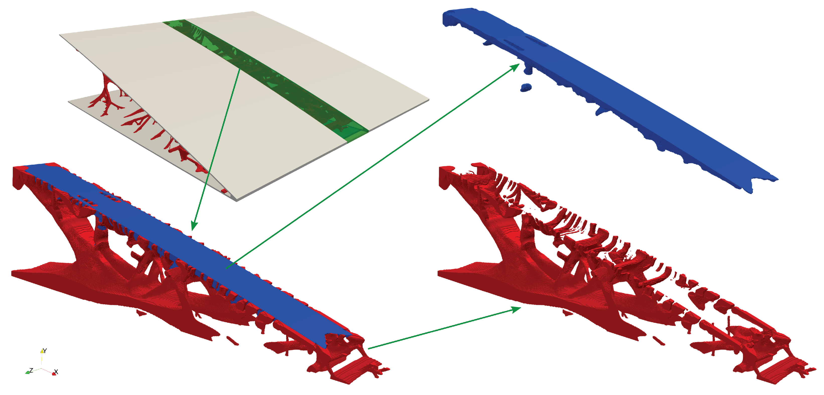
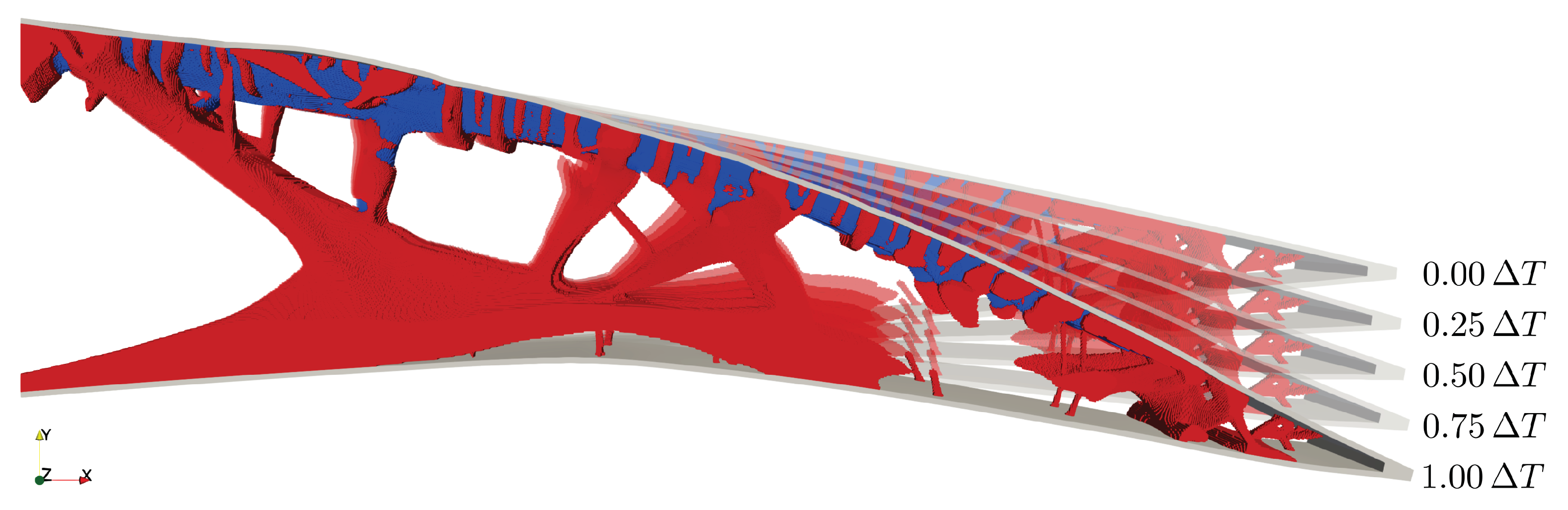
In Figure 7 and Figure 8, the actuator portion of the structure is isolated and highlighted. Here, we again see how a composite structure formed between the actuator and structural material, such that the actuator provided the wanted force/displacement characteristics for the morphing. From Figure 7, we see that defined compliant mechanisms with well-defined compliant hinges were formed under the actuator to distribute the bending moment throughout the structure. In Figure 8, the expansion for the actuator portion is shown, from 0 to 100. Here, the mechanism is seen to morph the structure.
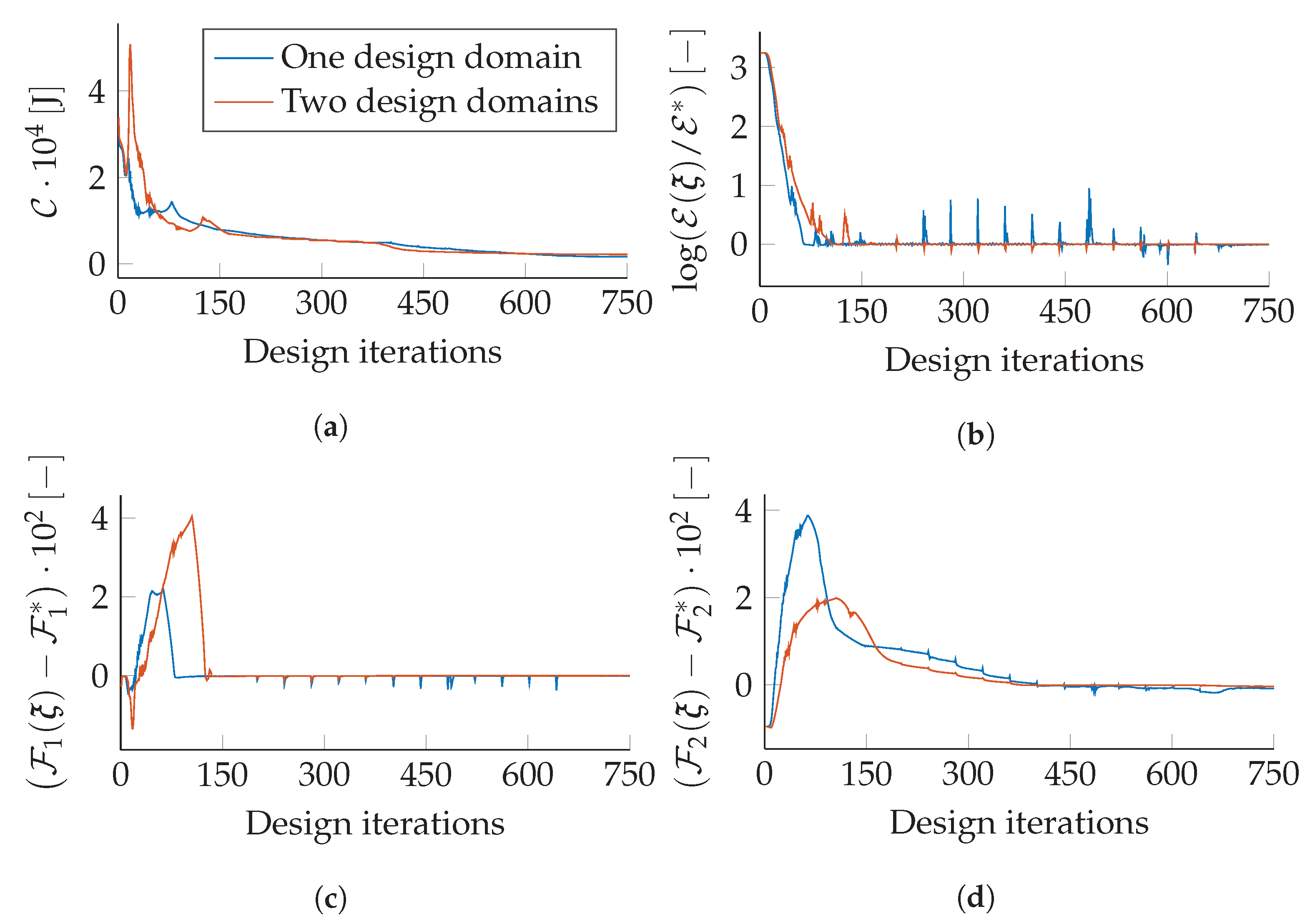
In Figure 9, the optimization iteration histories of the compliance, morphing displacement error constraint, and volume constraints are shown for the optimized designs with one and two design domains in Figure 4 and Figure 6. As seen, the volume constraints were violated at first to satisfy the morphing displacement error constraint and slowly satisfied. Compared to the initial designs, the optimized designs possessed the prescribed morphing functionality with enhanced structural stiffness.
The actuating material seemed to lump together in the two optimized designs, which makes the interpretations of a manufacturable design hard. For that reason, the feature-mapping approach seems essential to explore.
4.2. Feature Mapping Approach
The final result was obtained using the feature-mapping approach. An overview of the result is seen in Figure 10. The result looks similar to the result obtained with the density approach for two domains. We again see how a stiff structure was formed under and at the end of the actuator to provide stiffness to the trailing edge section.
In Figure 10, close-ups are highlighted; the close-up in the top-left corner shows how the structural material was forming cup-like features around the feature for connection between the actuator and structural material. The close-up in the lower-right shows how a hierarchical branching structure was forming, as also seen on the density approach results.
Despite having constraints on the actuating material in the form of the feature-mapping approach, it was evident that it is not enough to have strictly defined feature actuators as a cylinder. It was seen that the cylinder moved halfway out of the skin. This makes sense from a mechanical perspective, as a more significant bending moment can be achieved by moving more actuator material away from the structural mechanism.
Table 4 presents the structural compliance of the three optimized designs. While all designs satisfied the morphing constraint, it was seen that the compliance value of the structure with one design domain was lowest, as expected due to the increased design freedom. When we constrained the density approach to two domains, the compliance value increased by 32 % and to 88 % when using the feature-mapping approach, as the structures had continuously less design freedom.
It must be noted, as pointed out by [24], that feature mapping problems are hard and tend to become stuck in local minima. This observation holds also in this design problem as the convergence of the problem was slow and prone to local minima. Meanwhile, the structural material volume fraction constraint became inactive with a value of −0.019, while the actuating material volume fraction constraint was slightly violated with a value of 0.0034. This indicated that the actuator was not strong enough due to the geometric restriction in the feature-mapping approach so that more structural material could be used.
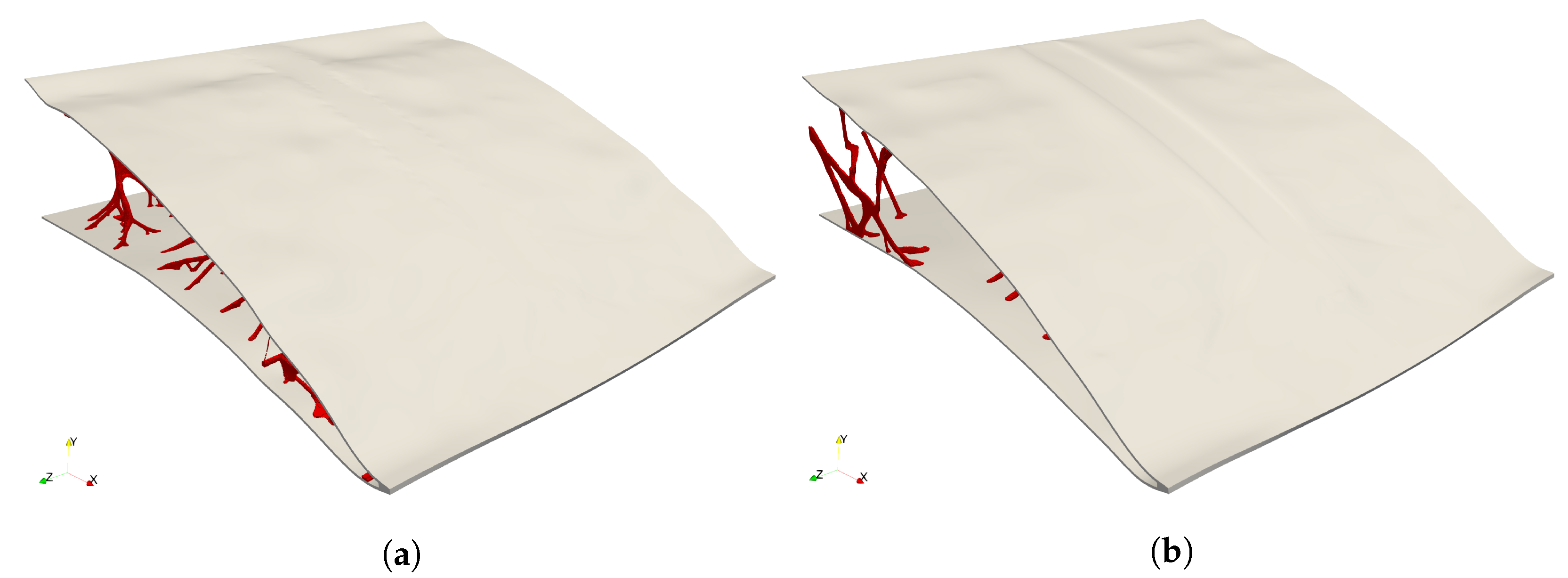
Figure 11 presents the deformed structure of the density approach with two domains (Figure 11a) and the feature-mapping approach (Figure 11b). It is seen that the skin had a small uneven section in both designs and bent a bit upwards near the corners at the end of the trailing edge. These minor defects are expected when the morphing displacement error is constrained to an aggregated 2.5% error. Either lowering the error or increasing the p-value in the p-mean could mitigate this.
5. Discussion
In the reviewed literature, no true 3D model were presented; both Kambayashi et al. [9] and De Gaspari [12] presented 2.5D results, where they performed optimization on 2D ribs connected to a 3D wing section. Our results cannot be compared to theirs as they solved different problems and applied external loading to drive their model. However, the work presented here showed the possibility of morphing model structures in 3D and that the result may give an alternative wing structure, compared to the traditional one consisting of ribs, as proposed by [31,32,33].
Furthermore, with the additions of the actuator design formulation, it is possible to design complex 3D mechanisms to achieve the desired morphing shape while considering internal actuation. The optimized design from the feature-mapping approach is easier to interpret into a manufacturable object, which makes the method more versatile.
It was seen that the convergence in the feature-mapping approach was very slow compared to the density approach. This is a drawback when using a new feature-mapping approach, as this method is very sensitive. For this reason, a very low move limit was allowed for the design variables. Simultaneously, feature mapping is prone to local minima issues that a low move limit does not alleviate.
The structural skin is an important component of a morphing trailing edge, as it is transferring external loading into the structure while it must remain smooth. In the presented work, the skin model was included as a passive component. One could imagine that if the skin were made softer or defined as an active design domain, included in the modeling as done in [13], a better result could be obtained. Here, the skin could be modeled as a shell structure.
6. Conclusions
This paper proposed a new approach to simultaneously optimize the mechanism and actuator design for morphing structures using the topology optimization method. The morphing was achieved by constraining an error between the actual and target shapes. Compliance minimization was utilized to ensure structural stiffness with respect to aerodynamic loading. The material properties were interpolated using a three-material model. The optimization problem of large-scale 3D morphing wings was solved in an efficient parallel framework with an unstructured grid.
Both the density and feature-mapping approaches were employed to design morphing trailing edge sections. Numerical results showed that composite actuators were formed to provide sufficient structural stiffness and actuating force in all the optimized designs. All three optimized designs showed rather unconventional design configurations and indicated that a 2D rib design may be inferior to a 3D design from a mechanical viewpoint. The feature-mapping approach provided the simplest actuator geometry, while the restriction on the actuator geometry led to the most compliant design due to limited actuating force.
The presented method and examples were applied to a very academic analysis for a 3D design domain and may serve as a baseline for further work and extensions. Nevertheless, we see this work as the first step towards the systematic design of weight-efficient airplane morphing wing structures. The following points will be taken into account in future work: (1) considering more in-depth analysis and optimization of the 3D trailing edge section for different load cases, multiple objectives, and different morphing targets; (2) considering anisotropic forces via the actuating material with anisotropic thermal expansion coefficients; (3) including skin design in the optimization, as seen in [13]; (4) including geometrical nonlinearity and manufacturing constraints to obtain a more realistic design.
Author Contributions
P.D.L.J.: methodology, software, formal analysis, writing—review editing, visualization. F.W.: methodology, conceptualization, resources, writing—review editing. I.D.: resources, writing—review editing. O.S.: methodology, conceptualization, resources, writing—review editing. All authors read and agreed to the published version of the manuscript.
Funding
The authors gratefully acknowledge the financial support of the Villum Foundation through the Villum Investigator project InnoTop.
Data Availability Statement
Geometry and design modeling data are available upon request to the main another.
Conflicts of Interest
The authors declare no conflict of interest.
References
- Holle, A.A. Plane and the Like for Aeroplanes. U.S. Patent N.1225711, 8 May 1917. [Google Scholar]
- Parker, F.H. The Parker Variable Camber Wing, Report No. 77; National Advisory Committee for Aeronautics (NACA): Kitty Hawk, NC, USA, 1920. [Google Scholar]
- Bendsøe, M.P.; Kikuchi, N. Generating optimal topologies in structural design using a homogenization method. Comput. Methods Appl. Mech. Eng. 1988, 71, 197–224. [Google Scholar] [CrossRef]
- Bendsøe, M.P. Optimization of Structural Topology, Shape, and Material; Springer: Berlin/Heidelberg, Germany, 1995. [Google Scholar] [CrossRef]
- Sigmund, O. On the Design of Compliant Mechanisms Using Topology Optimization. Mech. Struct. Mach. 1997, 25, 493–524. [Google Scholar] [CrossRef]
- Sigmund, O. Systematic Design of Micro and Macro Systems. In IUTAM-IASS Symposium on Deployable Structures, Theory and Applications; Springer: Dordrecht, The Neatherland, 2000; Volume 80, pp. 373–382. [Google Scholar] [CrossRef]
- Sigmund, O. Design of multiphysics actuators using topology optimization—Part I: One-material structures. Comput. Methods Appl. Mech. Eng. 2001, 190, 6577–6604. [Google Scholar] [CrossRef]
- Sigmund, O. Design of multiphysics actuators using topology optimization—Part II: Two-material structures. Comput. Methods Appl. Mech. Eng. 2001, 190, 6605–6627. [Google Scholar] [CrossRef]
- Kambayashi, K.; Kogiso, N.; Yamada, T.; Izui, K.; Nishiwaki, S.; Tamayama, M. Multiobjective Topology Optimization for a Multi-layered Morphing Flap Considering Multiple Flight Conditions. Trans. Jpn. Soc. Aeronaut. Space Sci. 2020, 63, 90–100. [Google Scholar] [CrossRef]
- Tong, X.; Ge, W.; Yuan, Z.; Gao, D.; Gao, X. Integrated design of topology and material for composite morphing trailing edge based compliant mechanism. Chin. J. Aeronaut. 2021, 34, 331–340. [Google Scholar] [CrossRef]
- Zhang, Z.; Ge, W.; Zhang, Y.; Zhou, R.; Dong, H.; Zhang, Y. Design of Morphing Wing Leading Edge with Compliant Mechanism. In Intelligent Robotics and Applications; Lecture Notes in Computer Science (Including Subseries Lecture Notes in Artificial Intelligence and Lecture Notes in Bioinformatics); Springer International Publishing: Berlin/Heidelberg, Germany, 2019; Volume 11740, pp. 382–392. [Google Scholar] [CrossRef]
- De Gaspari, A. Multiobjective Optimization for the Aero-Structural Design of Adaptive Compliant Wing Devices. Appl. Sci. 2020, 10, 6380. [Google Scholar] [CrossRef]
- Gomes, P.; Palacios, R. Aerodynamic Driven Multidisciplinary Topology Optimization of Compliant Airfoils. In Proceedings of the AIAA Scitech 2020 Forum, Orlando, FL, USA, 6–10 January 2020; American Institute of Aeronautics and Astronautics: Reston, VA, USA, 2020; Volume 1, pp. 2117–2130. [Google Scholar] [CrossRef]
- Gu, X.; Yanf, K.; Wu, M.; Zhang, Y.; Zhu, J.; Zhang, W. Integrated optimization design of smart morphing wing for accurate shape control. Chin. J. Aeronaut. 2021, 34, 135–147. [Google Scholar] [CrossRef]
- Dimino, I.; Amendola, G.; Di Giampaolo, B.; Iannaccone, G.; Lerro, A. Preliminary design of an actuation system for a morphing winglet. In Proceedings of the 2017 8th International Conference on Mechanical and Aerospace Engineering (ICMAE), Prague, Czech Republic, 22–25 July 2017; pp. 416–422. [Google Scholar] [CrossRef]
- Vecchia, P.; Corcione, S.; Pecora, R.; Nicolosi, F.; Dimino, I.; Concilio, A. Design and integration sensitivity of a morphing trailing edge on a reference airfoil: The effect on high-altitude long-endurance aircraft performance. J. Intell. Mater. Syst. Struct. 2017, 28, 2933–2946. [Google Scholar] [CrossRef] [Green Version]
- Drela, M. XFOIL 6.97; Massachusetts Institute of Technology: Cambridge, MA, USA, 2020. [Google Scholar]
- Cook, R.D.; Malkus, D.S.; Plesha, M.E.; Witt, R.J. Concepts and Applications of Finite Element Analysis, 4th ed.; John Wiley & Sons, Incorporated: Hoboken, NJ, USA, 2001. [Google Scholar]
- Bendsøe, M.P.; Sigmund, O. Topology Optimization; Springer: Berlin/Heidelberg, Germany, 2004; p. 381. [Google Scholar] [CrossRef]
- Bourdin, B. Filters in topology optimization. Int. J. Numer. Methods Eng. 2001, 50, 2143–2158. [Google Scholar] [CrossRef]
- Wang, F.; Lazarov, B.S.; Sigmund, O. On projection methods, convergence and robust formulations in topology optimization. Struct. Multidiscip. Optim. 2011, 43, 767–784. [Google Scholar] [CrossRef]
- Lazarov, B.S.; Sigmund, O. Filters in topology optimization based on Helmholtz-type differential equations. Int. J. Numer. Methods Eng. 2011, 86, 765–781. [Google Scholar] [CrossRef]
- Norato, J.; Haber, R.; Tortorelli, D.; Bendsøe, M.P. A geometry projection method for shape optimization. Int. J. Numer. Methods Eng. 2004, 60, 2289–2312. [Google Scholar] [CrossRef]
- Wein, F.; Dunning, P.D.; Norato, J.A. A review on feature-mapping methods for structural optimization. Struct. Multidiscip. Optim. 2020, 62, 1597–1638. [Google Scholar] [CrossRef]
- Wang, F. Systematic design of 3D auxetic lattice materials with programmable Poisson’s ratio for finite strains. J. Mech. Phys. Solids 2018, 114, 303–318. [Google Scholar] [CrossRef] [Green Version]
- Träff, E.A.; Sigmund, O.; Aage, N. Topology optimization of ultra high resolution shell structures. Thin-Walled Struct. 2021, 160, 107349. [Google Scholar] [CrossRef]
- Aage, N.; Lazarov, B.S. Parallel framework for topology optimization using the method of moving asymptotes. Struct. Multidiscip. Optim. 2013, 47, 493–505. [Google Scholar] [CrossRef]
- Balay, S.; Abhyankar, S.; Adams, M.; Brown, J.; Brune, P.; Buschelman, K.; Dalcin, L.; Dener, A.; Eijkhout, V.; Gropp, W.; et al. PETSC—Portable, Extensible Toolkit for Scientific Computation, Revision 3.13 ed.; Argonne National Laboratory: Lemont, IL, USA, 2020. [Google Scholar]
- Svanberg, K. The method of moving asymptotes—A new method for structural optimization. Int. J. Numer. Methods Eng. 1987, 24, 359–373. [Google Scholar] [CrossRef]
- Sandia. Cubit 13.2 User Documentation; Sandia National Laboratories: Albuquerque, NM, USA, 2019. [Google Scholar]
- Arena, M.; Amoroso, F.; Pecora, R.; Amendola, G.; Dimino, I.; Concilio, A. Numerical and experimental validation of a full scale servo-actuated morphing aileron model. Smart Mater. Struct. 2018, 27, 105034. [Google Scholar] [CrossRef]
- Concilio, A.; Dimino, I.; Pecora, R. SARISTU: Adaptive Trailing Edge Device (ATED) design process review. Chin. J. Aeronaut. 2020, 34, 187–210. [Google Scholar] [CrossRef]
- Dimino, I.; Andreutti, G.; Moens, F.; Fonte, F.; Pecora, R. Integrated Design of a Morphing Winglet for Active Load Control and Alleviation of Turboprop Regional Aircraft. Appl. Sci. 2021, 11, 2439. [Google Scholar] [CrossRef]
Figure 1.
Design problem for the morphing trailing edge section.

Figure 2.
An NACA 2414 2D airfoil profile is illustrated with the morphed trailing edge (red line). defines the reference coordinate system for the trailing edge region (blue dashed line), with the dimensions . The trailing edge section is highlighted; here the nodal points of the original profile, , and the nodal target points, , are shown. The blue line and dots show the error as the distance, d, for the node and target i.

Figure 3.
Illustration of the two density fields and two material fields. (a,b) show the density fields. (c) shows how the material model is realized for the density approach. (d) shows how the material model is realized for the feature-mapping approach; notice how the actuator material is dominating the material field when realizing the material model. As seen in (c,d), red material defines the structural material, while blue material defines the actuating material.

Figure 4.
Isometric view of the resulting topology from the density approach with one design domain. The skin on the top side is removed for viewing the internal structure. The field is realized with a threshold value of 0.5. On the right side of the figure, a slice of the bottom side of the actuator portion is shown; notice the level of detail achieved with the fine mesh discretization. In the top left corner, merging, plate-like, and truss structures are highlighted.

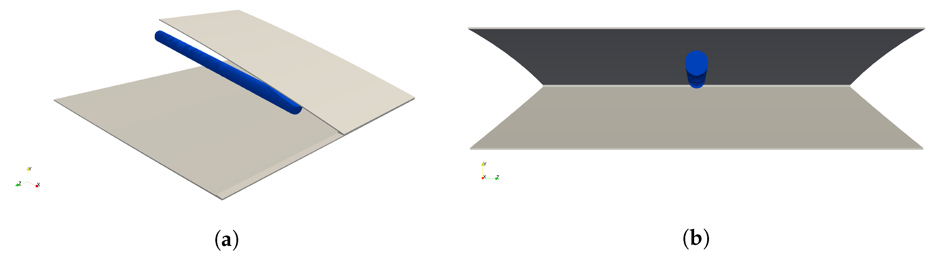
Figure 5.
Initial placement of feature for the feature-mapping approach. (a) Isometric view. (b) Back view.
Figure 5.
Initial placement of feature for the feature-mapping approach. (a) Isometric view. (b) Back view.

Figure 6.
Isometric view of the optimized topology from the density approach with two design domains. The skin on the top side is removed for viewing the internal structure. The field is realized with a threshold value of 0.5. The top close-up shows the structural material forming a composite with the actuating material for optimizing the actuator capabilities. The bottom close-up shows the truss structure merging as thin-plate structure.

Figure 7.
Isolation of actuator portion of the resulting topology from the density approach with two design domains. The field is realized with a threshold value of 0.5. Notice how a very complex structural design formed around the actuating material.
Figure 7.
Isolation of actuator portion of the resulting topology from the density approach with two design domains. The field is realized with a threshold value of 0.5. Notice how a very complex structural design formed around the actuating material.

Figure 8.
Demonstration of the morphing capabilities of the resulting topology from the density approach with two design domains. The field is realized with a threshold value of 0.5. The shown section is the same that as highlighted in Figure 7.
Figure 8.
Demonstration of the morphing capabilities of the resulting topology from the density approach with two design domains. The field is realized with a threshold value of 0.5. The shown section is the same that as highlighted in Figure 7.

Figure 9.
Optimization iteration histories of the two density approach examples. (a) Compliance. (b) Morphing displacement error constraint. (c) Volume Constraint 1. (d) Volume Constraint 2.
Figure 9.
Optimization iteration histories of the two density approach examples. (a) Compliance. (b) Morphing displacement error constraint. (c) Volume Constraint 1. (d) Volume Constraint 2.

Figure 10.
Isometric view of the resulting topology from the feature-mapping approach. The skin on the top side is removed for viewing the internal structure. The field is realized with a threshold value of 0.5. The top-left close-up shows how the structural material is well connected to the actuation material. In the top-right corner, the actuator is isolated; notice how a compliant mechanism is formed under the actuator. The bottom-right close-up shows how a hierarchical branching structure is forming.

Figure 11.
Deformation fields of (a) Density approach with two design domains. (b) Feature mapping. Small defects in the skin are seen as a result of the morphing displacement error.
Figure 11.
Deformation fields of (a) Density approach with two design domains. (b) Feature mapping. Small defects in the skin are seen as a result of the morphing displacement error.


Table 1.
Material properties for the trailing edge model.
| [-] | [-] | [-] | [-] | ||
| 72 | 70 | 0.32 | 0.32 | 0 | 0.1 |
Table 2.
Upper bound values for the constraints.
| 5 | 1 | 2.5 |
Table 3.
Initial normalized design variables for the feature mapping approach.
| [-] | [-] | [-] | [-] | [-] | [-] | [-] |
| 0.50 | 0.65 | 0.00 | 143/256 | 144/256 | 0.5 | 0.8 |
Table 4.
Resulting compliance values from the three presented designs.
| Density Approach | Density Approach | Feature Mapping | |
|---|---|---|---|
| (One Domain) | (Two Domains) | Approach | |
Publisher’s Note: MDPI stays neutral with regard to jurisdictional claims in published maps and institutional affiliations. |
© 2021 by the authors. Licensee MDPI, Basel, Switzerland. This article is an open access article distributed under the terms and conditions of the Creative Commons Attribution (CC BY) license (https://creativecommons.org/licenses/by/4.0/).
Share and Cite
MDPI and ACS Style
Jensen, P.D.L.; Wang, F.; Dimino, I.; Sigmund, O. Topology Optimization of Large-Scale 3D Morphing Wing Structures. Actuators 2021, 10, 217. https://0-doi-org.brum.beds.ac.uk/10.3390/act10090217
AMA Style
Jensen PDL, Wang F, Dimino I, Sigmund O. Topology Optimization of Large-Scale 3D Morphing Wing Structures. Actuators. 2021; 10(9):217. https://0-doi-org.brum.beds.ac.uk/10.3390/act10090217
Chicago/Turabian StyleJensen, Peter Dørffler Ladegaard, Fengwen Wang, Ignazio Dimino, and Ole Sigmund. 2021. "Topology Optimization of Large-Scale 3D Morphing Wing Structures" Actuators 10, no. 9: 217. https://0-doi-org.brum.beds.ac.uk/10.3390/act10090217
Note that from the first issue of 2016, this journal uses article numbers instead of page numbers. See further details here.