
Optimal Design of Magneto-Force-Thermal Parameters for Electromagnetic Actuators with Halbach Array

1
School of Mechanical and Automotive Engineering, Qingdao University of Technology, Qingdao 266000, China
2
Harbin Institute of Technology, School of Mechatronics Engineering, Harbin 150001, China
*
Author to whom correspondence should be addressed.
Actuators 2021, 10(9), 231; https://0-doi-org.brum.beds.ac.uk/10.3390/act10090231
Submission received: 5 August 2021
/
Revised: 2 September 2021
/
Accepted: 6 September 2021
/
Published: 9 September 2021
(This article belongs to the Special Issue Miniature and Micro-Actuators)
Abstract
:A magnetic levitation isolation system applied for the active control of micro-vibration in space requires actuators with high accuracy, linear thrust and low power consumption. The magneto-force-thermal characteristics of traditional electromagnetic actuators are not optimal, while actuators with a Halbach array can converge magnetic induction lines and enhance the unilateral magnetic field. To improve the control effect, an accurate magnetic field analytical model is required. In this paper, a magnetic field analytical model of a non-equal-size Halbach array was established based on the equivalent magnetic charge method and the field strength superposition principle. Comparisons were conducted between numerical simulations and analytical results of the proposed model. The relationship between the magnetic flux density at the air gap and the size parameters of the Halbach array was analyzed by means of a finite element calculation. The mirror image method was adopted to consider the influence of the ferromagnetic boundary on the magnetic flux density. Finally, a parametric model of the non-equal-size Halbach actuator was established, and the multi-objective optimization design was carried out using a genetic algorithm. The actuator with optimized parameters was manufactured and experiments were conducted to verify the proposed analytical model. The difference between the experimental results and the analytical results is only 5%, which verifies the correctness of the magnetic field analytical model of the non-equal-size Halbach actuator.
1. Introduction
An electromagnetic actuator based on the Lorentz force principle is the core device of a magnetic levitation isolation platform, and it can eliminate the mechanical attachment between the stationary and moving parts of an actuator [1,2,3]. An actuator with high magnetic flux density, small volume and little hot loss is superior to others in obtaining suitable control performance. Compared with traditional actuators, the non-equal-size Halbach array can converge magnetic induction lines and enhance the unilateral magnetic field. Actuators with a Halbach array are characterized by small thrust fluctuation, high positioning accuracy, short response time, low influence of hysteresis effect and simple thrust control, all of which have considerable application prospects in relation to micro-vibration control in space [4,5,6,7].
Scholars have mainly focused on the dynamics model, the optimization of the magnetic circuit parameters, improving the electromagnetic thrust, reducing the thrust fluctuation, controlling the temperature rise effect, etc. [8]. Kou proposed a flat-type vertical-gap passive magnetic levitation vibration isolator (FVPMLVI) for an active vibration isolation system [9]. However, the author did not analyze the effect of the yoke portion on the magnetic field. Typical structure and rectangular structure voice coil motors were analyzed by their volumetric changes [10]. However, there was a lack of research into the dimensional parameters of permanent magnets. Lin designed a novel three-DOF spherical voice coil motor (VCM) and studied the simulation of the magnetic field distribution for rotation in relation to the x-axis and z-axis [11]. However, no specific analytical model of the magnetic field was involved. Wei developed an electromagnetic actuator that concurrently realized two working functions of vibration suppression and energy regeneration [12]. The experimental results also showed that the amplitude of the controlled object can be suppressed within 5.5%. However, the control accuracy of electromagnetic actuators has not been verified. Liu theorized a differential electromagnetic actuator for a magnetic levitation vibration isolation system. Linear output force and absolute velocity feedback were used to improve the vibration isolation performance [13]. However, a mathematical model of the magnetic field of the actuator has not been analyzed. A combination of the finite element method and the analytical method was discussed by Han, as was the eddy current loss of coil windings. The accuracy of thermal analysis predictions was verified through experiments [14]. A short-stroke planar motor with a non-integrated winding structure and an integrated winding structure was analyzed by Zhang [15]. The magnetic field distribution of the air gap was obtained using a finite element simulation. However, an analytical model is yet to be established. Considering the nonlinear saturation effect of ferromagnetic materials, a modified magnetic equivalent circuit (MEC) model was used by Liu to more accurately estimate the magnetic flux density at the air gap [16]. The magnetic leakage phenomenon in the middle of the magnetic conjugate was studied by Smith. The method of dividing permanent magnets and adjusting the pole distance was proposed to reduce magnetic leakage and thrust fluctuation [17]. A stacked giant magnetostrictive actuator was designed by He, and a magnetic field distribution model was established to accurately describe the magnetic field of the actuator, which improved the operating accuracy of the actuator in question [18]. A novel voice coil motor actuator that could generate a high actuating force was proposed by Kim; the magnetic field at the air gap was analyzed based on the charge model, which was verified using a 3D finite element method (FEM) simulation [19].
In order to improve the control effects, an accurate mathematical model of an actuator should be established by considering the impacts of the end effect and ferromagnetic boundary. In this paper, a non-equal-size actuator based on the Halbach array was designed for a magnetic levitation isolation platform. Compared with a traditional magnet, the Halbach array can converge magnetic induction lines and enhance the unilateral magnetic field. The magnetic flux density fluctuation of an equal-size Halbach array is higher than a non-equal-size Halbach array. By designing non-equal-size permanent magnets and optimizing the dimensional parameters, a uniformly distributed air-gap magnetic field can be obtained, which is conducive to improving the accuracy of an actuator and reducing its harmonic distortion. A magnetic field analytical model of a non-equal-size Halbach actuator was established and the magnetic flux density at the air gap was calculated. The analytical expression and numerical simulation of the magnetic flux density and fluctuation degree were compared between the Halbach array and the traditional permanent magnet. The influence of size parameters and the ferromagnetic boundary on the magnetic field of the Halbach array were studied. To obtain an actuator with uniform magnetic flux density distribution, high control accuracy, low power consumption and light mass, the multi-objective optimization design of a Halbach actuator was carried out and optimal magnetic-force-thermal parameters were obtained.
2. Modeling of the Magnetic Field of a Non-Equal-Size Halbach Array
2.1. Spatial Magnetic Field Analytical Model of Rectangular Permanent Magnets
The electric field distribution of a charged object in space can be considered as a superposition of an electric field intensity generated by electric charges. The magnetic field distribution of a uniformly magnetized rectangular permanent magnet can similarly be equated to a vector superposition of magnetic fields generated by a body magnetic charge inside the permanent magnet and surface magnetic charge on the surface [20]. The expressions for the body and surface charges can be written as follows:
where means the magnetization intensity, means the normal vector of the magnetic charge plane, means the residual flux density of permanent magnets, and means the vacuum permeability.
The rectangular permanent magnet is assumed to be uniformly magnetized. Therefore, the volume magnetic charge density is 0, and the surface magnetic charge density is determined by the spatial magnetic field distribution of the rectangular permanent magnet.
There is no free current in the region of the static magnetic field generated by the rectangular permanent magnet; therefore, the expression of Maxwell Equations can be simplified as follows:
where is the magnetic flux density and is the magnetic field intensity.
The expressions for the scalar magnetic potential and magnetic properties of the magnetic field strength can be written as follows:
According to Equations (3)–(6), Equation (7) can be deduced as follows:
The integral expression for the scalar magnetic potential can be obtained according to Green’s function.
where means the observation point location vector and means the field source point position vector.
According to Equation (8), the expression for the magnetic flux density of a rectangular permanent magnet in space can be written as follows:
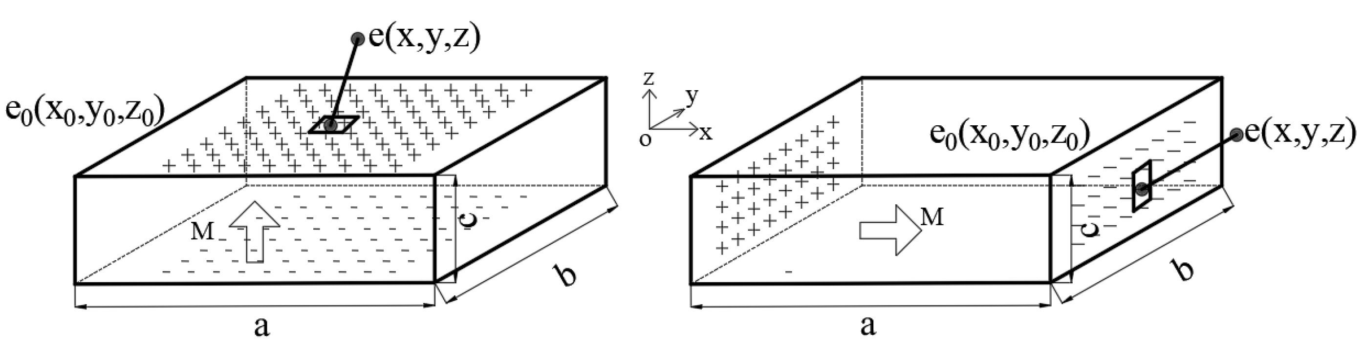
The equivalent magnetic charge models of the vertically magnetized and horizontally magnetized rectangular permanent magnets are shown in Figure 1. The vertically magnetized permanent magnets are equivalent to the upper and lower magnetic charge planes, and the horizontally magnetized permanent magnets are equivalent to the left and right magnetic charge planes [21].
The geometric center of the rectangular permanent magnets is used as the origin of the coordinate axes. The magnetic flux density of two kinds of rectangular permanent magnets in space can be expressed as follows:
The magnetic field required for the Lorentz force is mainly provided by the z-axis component of the magnetic flux density at the air gap. The magnetic flux density of the z-axis component of the rectangular permanent magnets in two magnetizing directions is given as follows:
2.2. Parameterized Magnetic Field Model
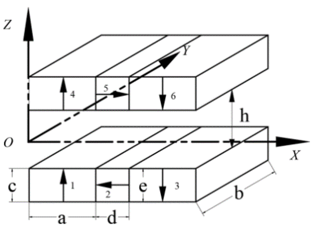
Based on the equivalent magnetic charge method, the magnetic flux density of the vertically and horizontally magnetized rectangular permanent magnets at any point in space was deduced. In order to solve the magnetic flux density at the air gap of a non-equal-size Halbach array, a spatial coordinate system was established at the center of the z-axis of the air gap. The length, width and height of the vertical and horizontal magnetized permanent magnets are set as variables. A parameterized magnetic field model of the non-equal-size Halbach array was established, as shown in Figure 2.
The permanent magnets in different magnetizing directions in the magnetic field of Halbach array are numbered. According to the parameterized model, the boundary coordinates are determined as follows:
According to the superposition principle, the z-axis component of the flux density at the air gap can be expressed as follows:
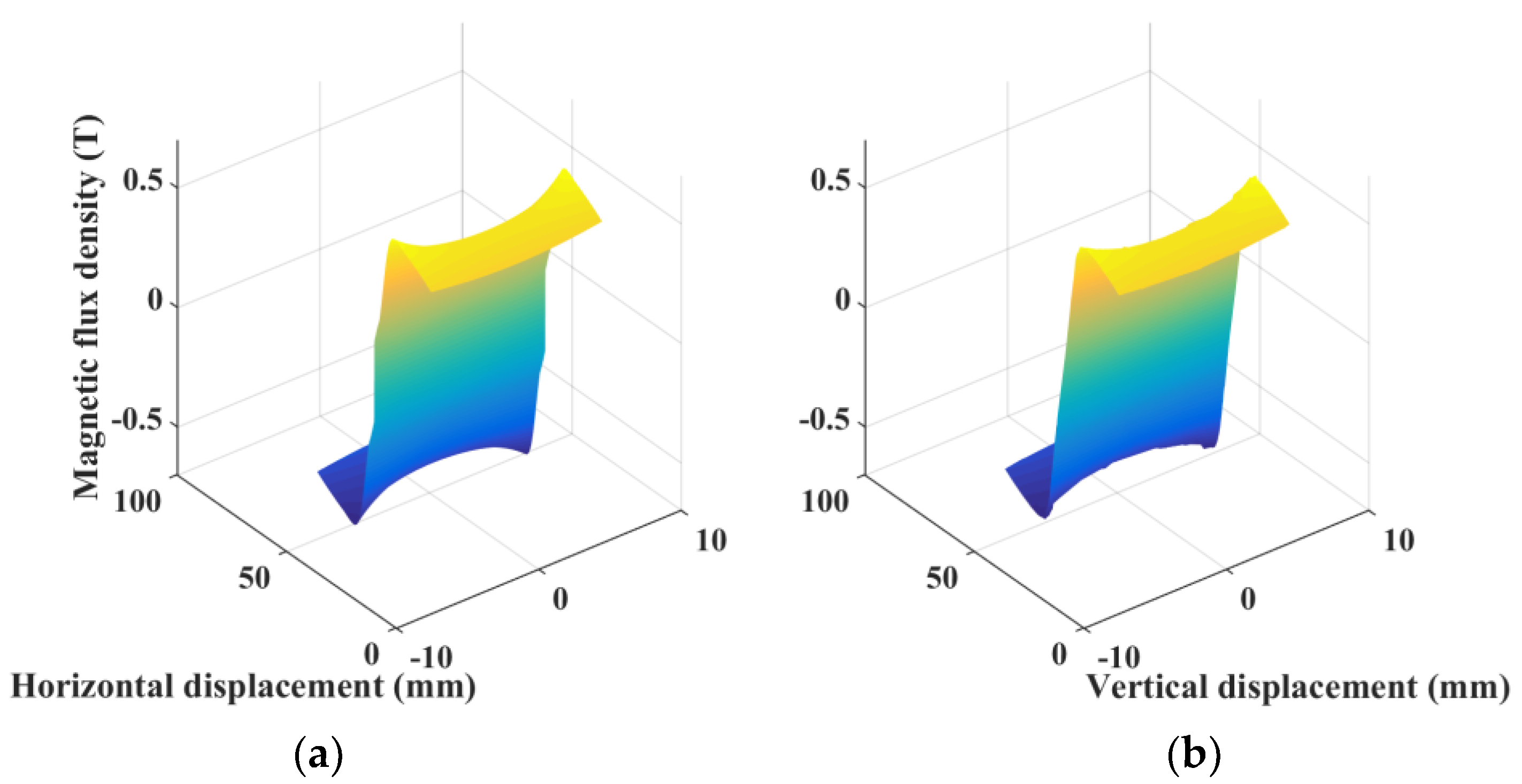
Ansys was used to calculate the magnetic flux density at the air gap along the horizontal direction (x-axis) and the vertical direction (z-axis). A comparison between the analytical results and the simulation results are shown in Figure 3.
The difference between the analytical value and the finite element simulation value of the magnetic flux density along the vertical direction is about 5%. The deviation between the analytical value and the simulation value along the horizontal direction is about 3%. Due to the end effect of the permanent magnet, the deviation between the two calculated results is 5–10%, which is within the allowable error range. It can be concluded that the magnetic field analytical model of the parameterized Halbach actuator is accurate.
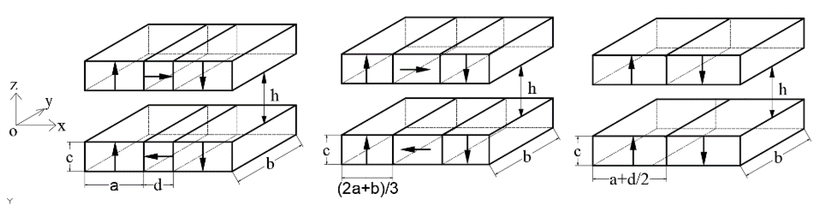
2.3. Comparison of Magnetic Flux Density between the Non-Equal-Size Halbach Array, Equal-Size Halbach Array and Conventional Magnet Groups
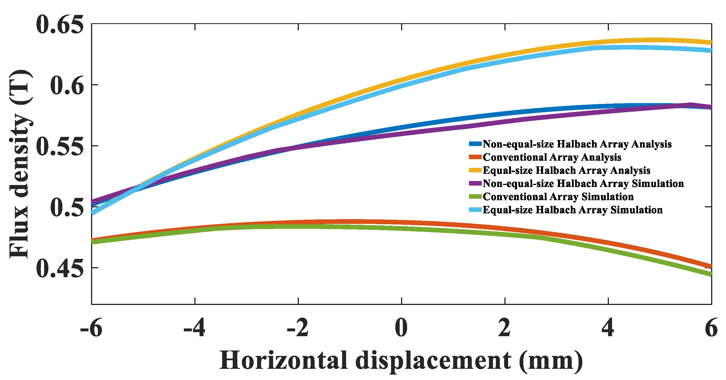
The electromagnetic actuator is required to enhance the intensity of the magnetic field and reduce the thrust fluctuation as much as possible, which requires a high magnetic flux density at the air gap and a uniform distribution of magnetic induction lines. The non-equal-size Halbach array, equal-size Halbach array and conventional array models are displayed in Figure 4. The analytical results and the simulation results of the magnetic field at the air gap are shown in Figure 5.
The average magnetic flux density of the equal-size Halbach array and non-equal-size Halbach array is about 23 and 17% higher than conventional array, respectively. It indicates that the actuator of the Halbach array outputs more thrust under the same current excitation.
The expression of magnetic flux density fluctuation is calculated as follows:
where means the air gap flux density maximum and means the air gap flux density minimum.
Within the effective stroke of the coil, the fluctuation of the non-equal-size Halbach array and the equal-size Halbach array are shown in Table 1.
It can be seen that the magnetic flux intensity of the equal-size Halbach array is a little greater than the non-equal-size Halbach array. However, the end effect and the fluctuation of the magnetic flux density of the non-equal-size Halbach array can be reduced more significantly.
3. Effect of the Dimensional Parameters of the Halbach Array
3.1. Effect of the Width of the Horizontal Magnetized Permanent Magnet
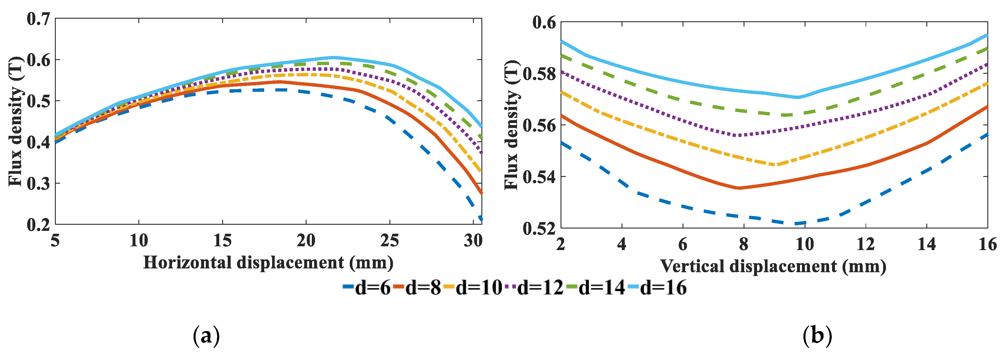
The purpose of horizontal magnetized permanent magnets is to enhance the magnetic flux density and reduce the effect of the permanent magnet end effect at the air gap. The sizes of the vertical magnetized permanent magnet and the air gap distance remain unchanged. Then, the relationship between size d of the horizontal magnetized permanent magnet and the magnetic flux density at the air gap is apparent (Figure 6).
3.2. Effect of Width Ratio of the Vertically and Horizontally Magnetized Permanent Magnets
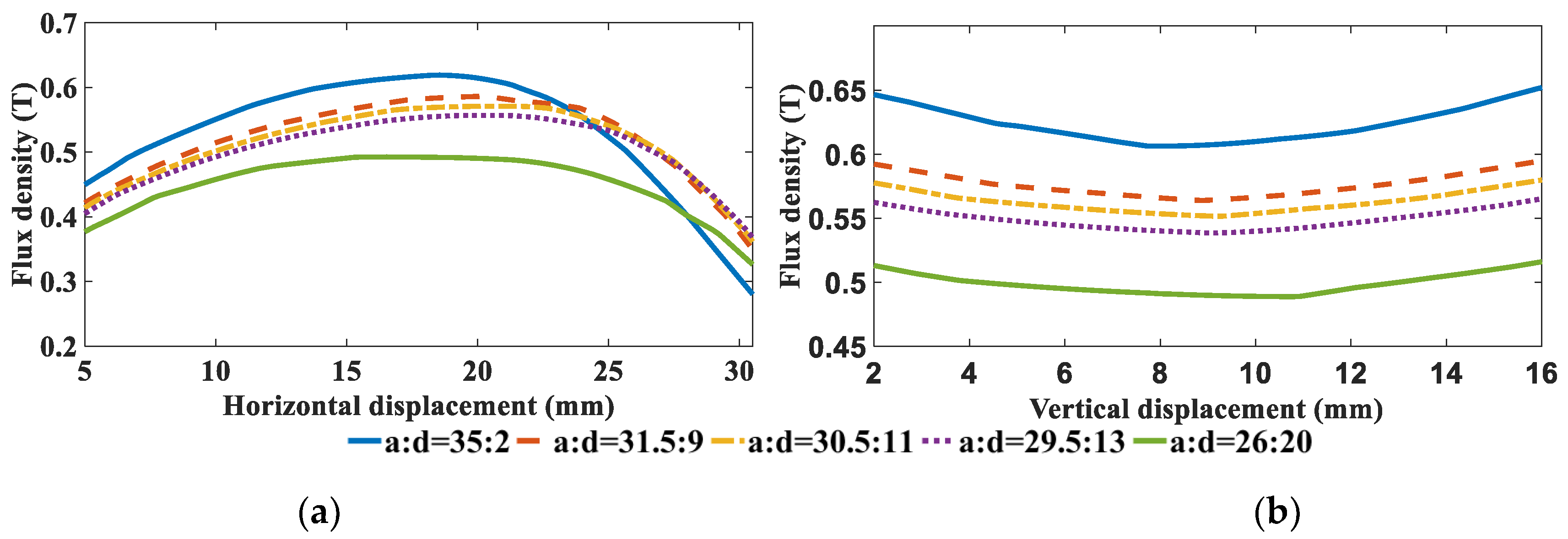
The maximum width of the actuator is set as the same width as the Halbach array. Additionally, the total width, length and height of the Halbach array are constant. The relation between the width ratio and the magnetic flux density was then simulated, as shown in Figure 7.
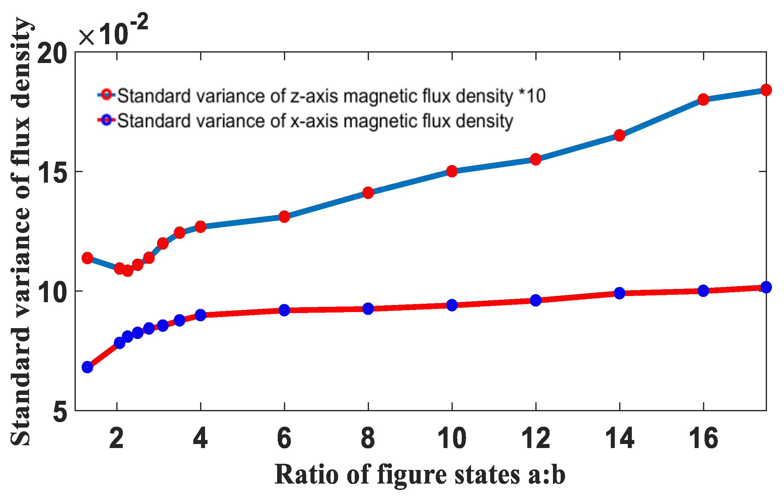
In the area far from the horizontal magnetized permanent magnet, the vertical magnetized permanent magnet dominates the magnetic field. Increasing the width ratio enhances the magnetic field along the horizontal direction. In the area near the horizontal magnetized permanent magnet, the increase in the magnetic flux density caused by the increase in the width of the horizontal magnetized permanent magnet is higher than the decay caused by the decrease in the width of the vertical magnetized permanent magnet. Thus, the magnetic flux density in the horizontal direction decreases with the increase in the width ratio. The standard variance of magnetic flux density in the x-axis and z-axis directions is shown in Figure 8.
When the text states a:d = 3:1, the magnetic flux density along the x-axis direction is stronger and the magnetic induction lines are more uniform. When the text states a:d = 2.5–3.5, the magnetic flux density along the z-axis direction has a smaller standard variance, which proves that the magnetic induction lines are more uniformly distributed.
4. Effect of Ferromagnetic Boundary
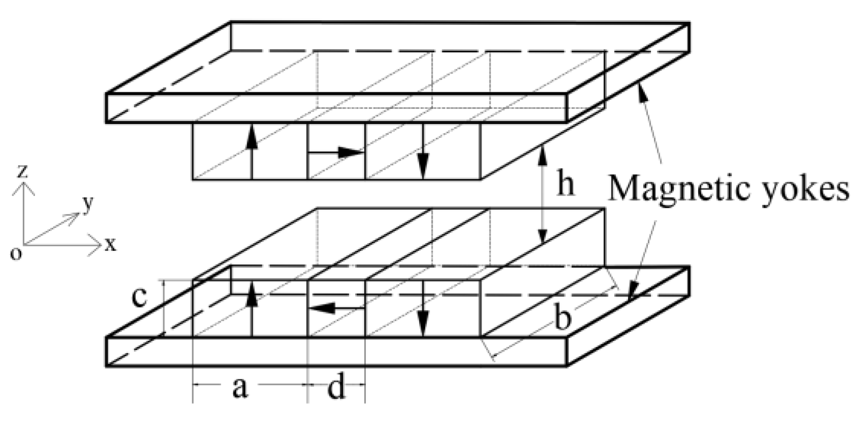
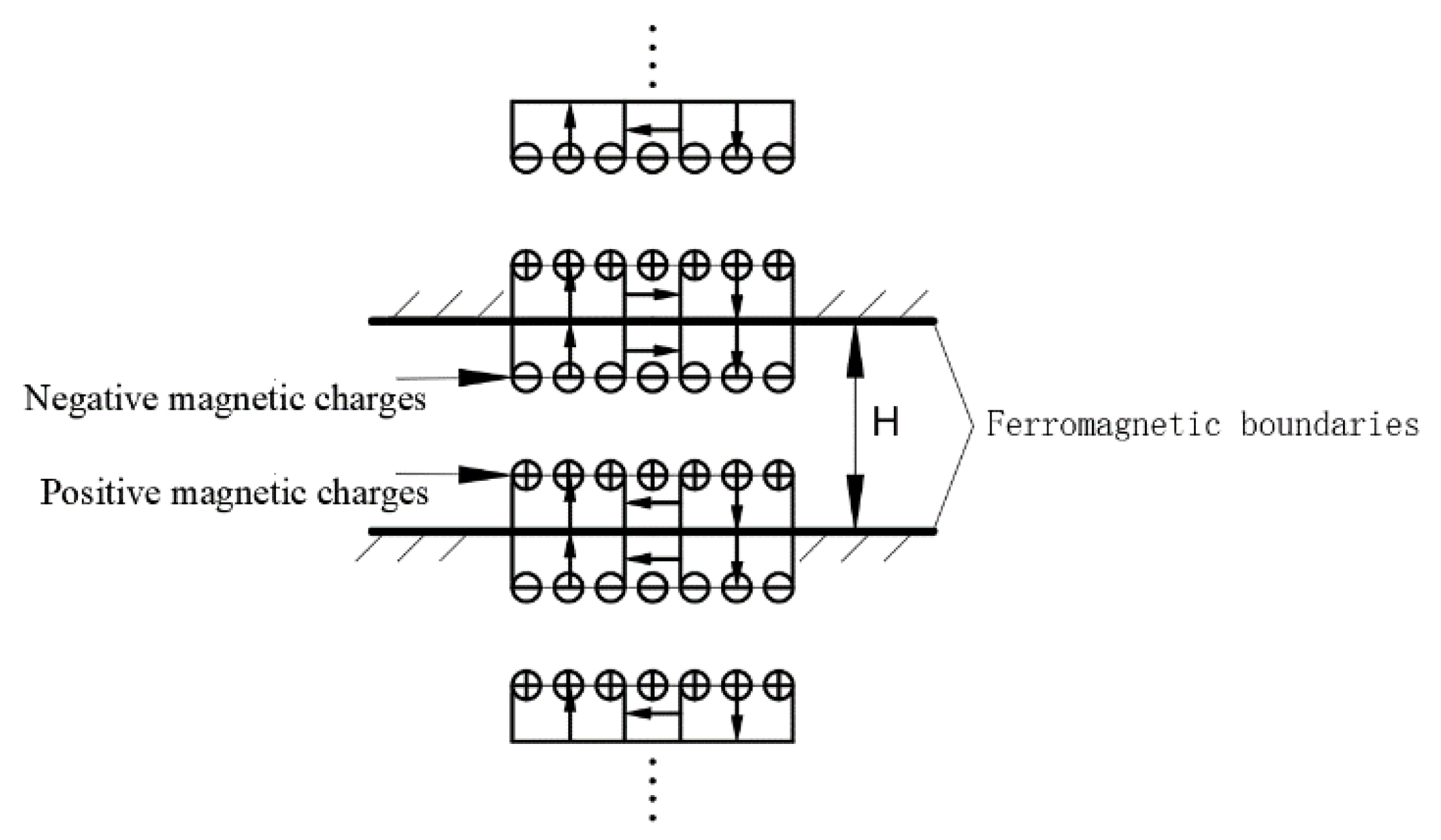
The designed actuator has bilateral ferromagnetic boundaries, as shown in Figure 9. It contains six rectangular permanent magnets and two magnetic yokes at the top and bottom. The existence of ferromagnetic boundaries has a certain influence on the magnetic flux density at the air gap compared to that without ferromagnetic boundaries [22]. The influence of the ferromagnetic boundary on the original magnetic field was calculated using the mirror method, which used the equivalent magnetic charge behind the boundary to equate its influence. The actual spatial distribution of the magnetic field is formed by the superposition of the original magnetic field and the mirror field.
A schematic diagram of the mirror image of the magnetic charge surface of the Halbach array under bilateral ferromagnetic boundary conditions is shown in Figure 10. H is the distance between the bilateral ferromagnetic boundaries. Theoretically, there are infinite sets of mirror images of the magnetic charge surface.
The analytical expression for the magnetic flux density at the air gap can be calculated according to the mirror image principle and the superposition principle as follows:
The ferromagnetic boundary material parameters are shown in Table 2.
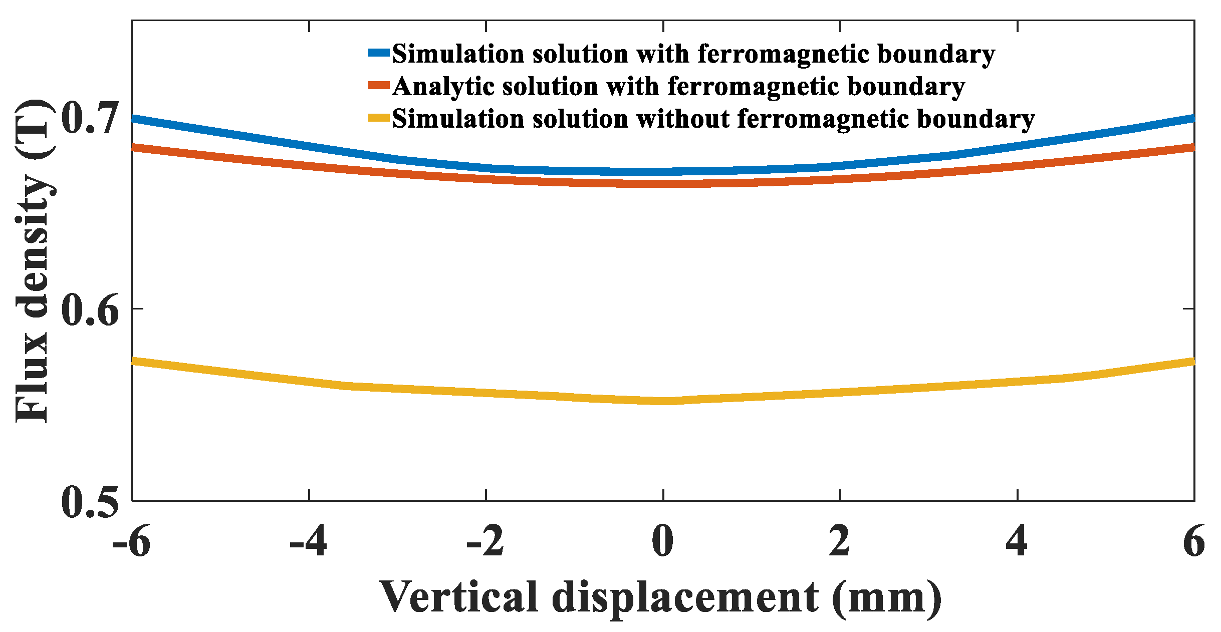
A comparison between the simulation results and the analytical results of the magnetic flux density at the air gap magnetic field is shown in Figure 11. It can be seen that the average magnetic flux density along the z-axis with a ferromagnetic boundary is 22% higher than that without a ferromagnetic boundary. This is because the ferromagnetic boundary can concentrate magnetic force lines and enhance magnetic field strength. The maximum deviation between the simulation and the analytical calculation is 2.2%. Additionally, the analytical result derived using the mirror method is in good agreement with the finite element simulation value. Since one set of mirror images is superimposed for analytical value, the analytical value is smaller than the simulation value.
5. Optimized Design
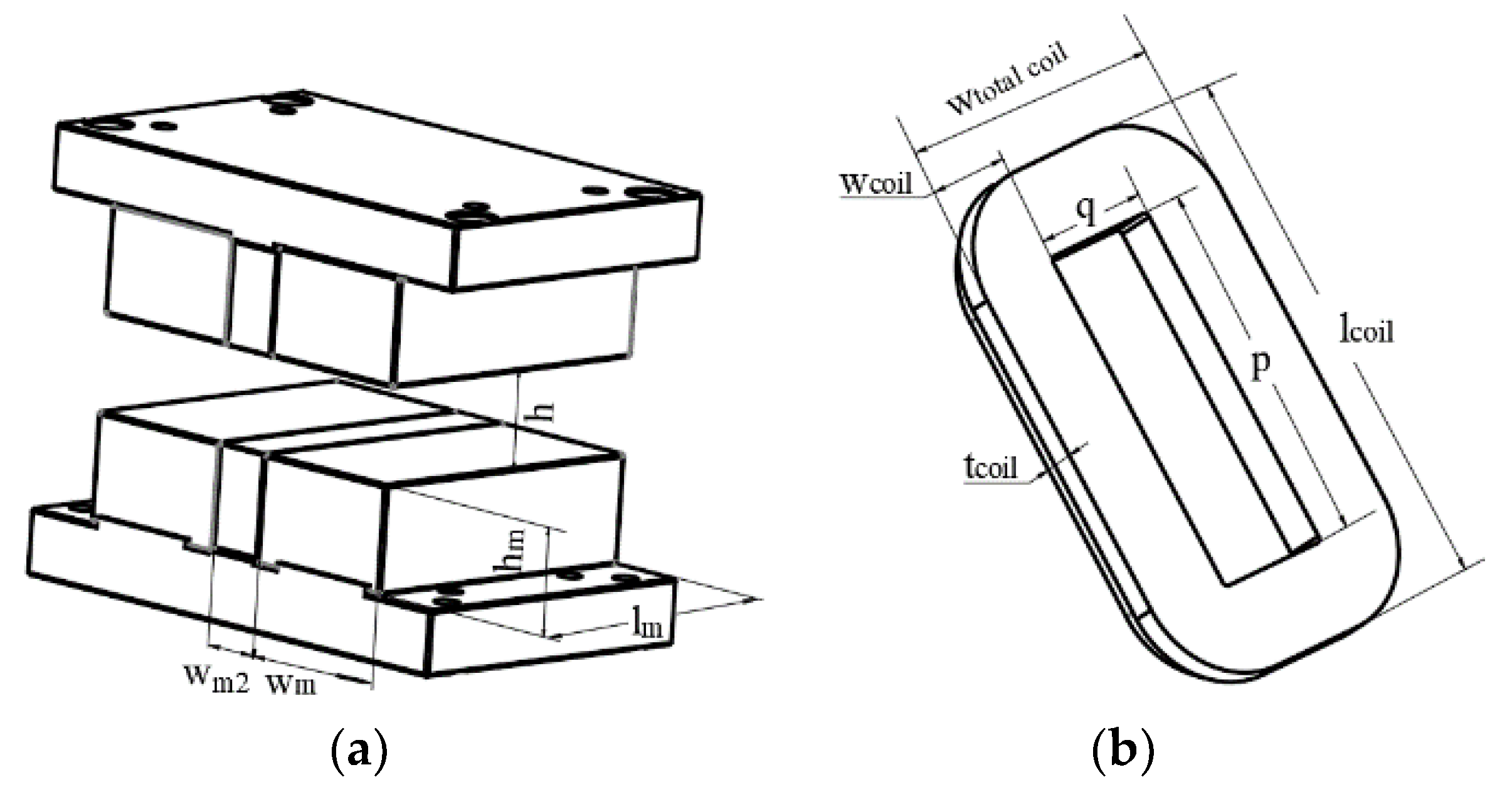
The mechanical structure of the actuator consists of a kinematic coil and a stator Halbach array, and the parametric model is shown in Figure 12.
Two objectives are needed for optimization. First, the magnetic flux density at the air gap is maximized and uniformly distributed. Second, the minimum coil mass and minimum thermal power consumption should be obtained. A genetic algorithm was adopted to obtain the actuator with optimal magnetic-force-thermal parameters.
According to the magnetic field analytical model of the non-equal-size Halbach array, and when considering the influence of the ferromagnetic boundary, the approximate relationship between the magnetic field at the center of the air gap and the parameters of the actuator is as follows:
where means the width of the vertically magnetized permanent magnet, means the width of the horizontally magnetized permanent magnet, means the length of the vertically magnetized permanent magnet, means the height of the vertically magnetized permanent magnet and means the length of the air gap.
When the width of the horizontal magnetized permanent magnet is greater than 10mm, and the width ratio of vertical and horizontal magnetized permanent magnet is 2.5–3.5, the magnetic field is smooth and uniform, and magnetic flux density can reach its maximum value.
The optimization objectives are expressed as follows:
where is the coil current, is the wire resistivity, is the coil volume, is the wire diameter, is the wire density and is the copper fill rate. The weight is defined as and can be set as 0.6 for the actuator.
The dimension constraints are given as Equation (19), including the relative position conditions of the coil and the Halbach array and actuator boundary dimension constraints.
where means the coil thickness, means the coil winding case thickness, means the coil single side width, means the total coil width, means the coil length and means the maximum design size of the actuator.
Based on a genetic algorithm, the optimal air gap size, minimum coil mass and minimum thermal dissipation are calculated. A comparison with the parameters before and after optimization is shown in Table 3.
The output force range of one single actuator is 0.1–50 N, and the current accuracy is 0.005A; force constants can be estimated as follows:
The force constant after optimization is smaller than the design index. According to the minimum current condition of the system, the control requirement of minimum Lorentz force can be satisfied.
6. Experimental Section
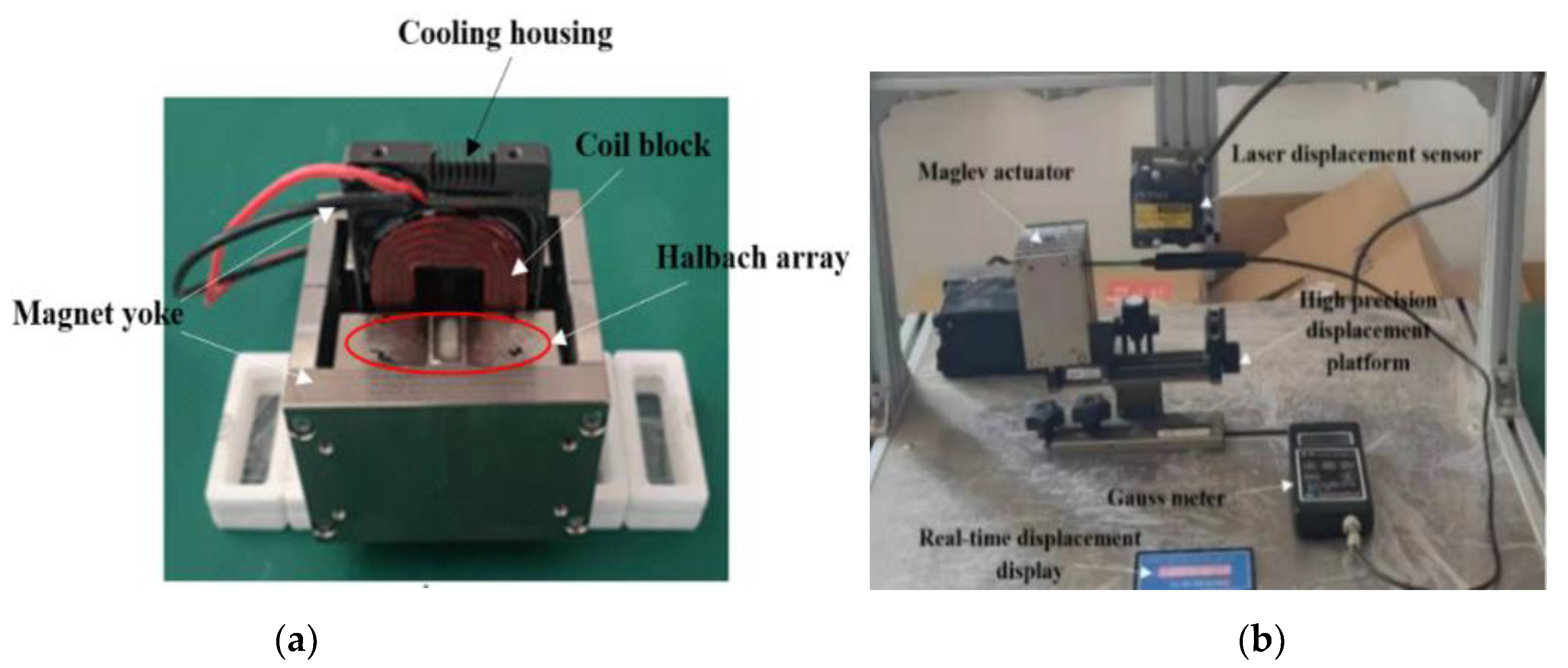
An actuator prototype was manufactured with optimized parameters, and the experimental setup is shown in Figure 13. The actuator was fixed on a high-precision displacement platform and a Gauss meter probe was mounted on a motion axis with a laser displacement sensor. The position of the Gauss meter probe at the air gap was adjusted by a real-time position control system to measure the magnetic flux density along the z-axis and x-axis directions at the air gap, respectively.
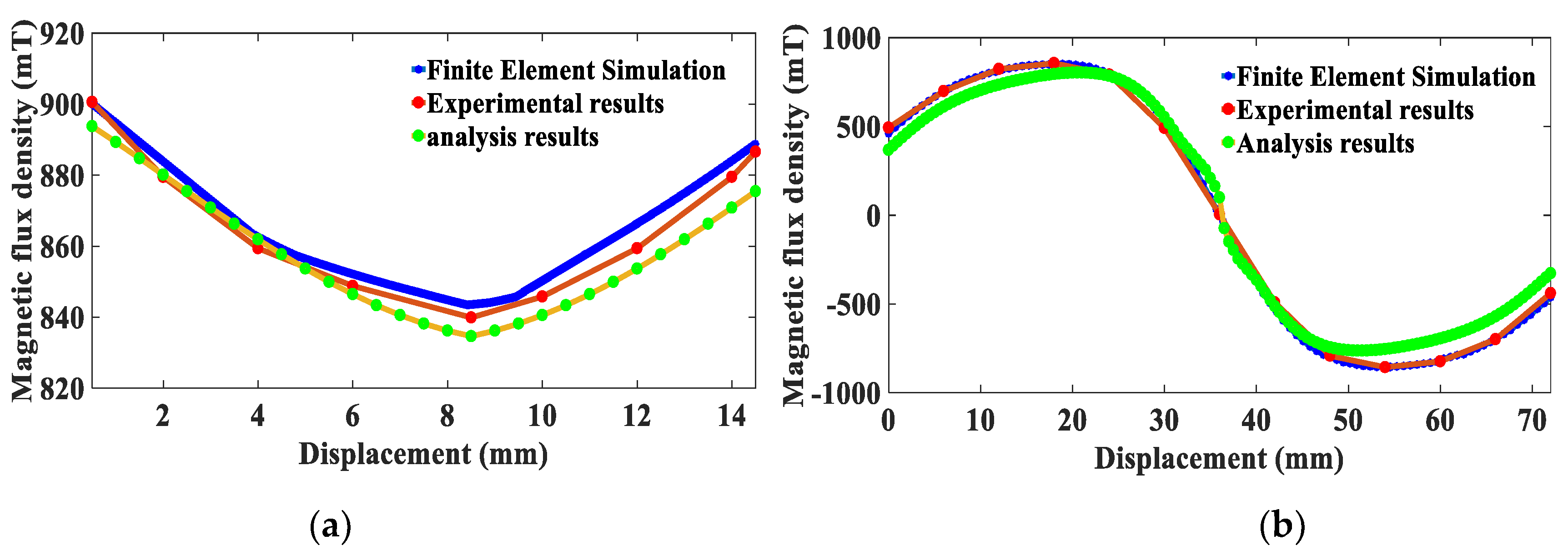
The measured results were compared with the finite element simulation results and analysis results, as shown in Figure 14. Within the effective stroke of the actuator, the experimental results show that the average air gap flux density in the z-axis direction is 0.85T, with a flux density fluctuation of 4%, while the average flux density in the x-axis direction is 0.86T, with a flux density fluctuation of 3.8%.
7. Conclusions
A magnetic field analytical model of a non-equal-size Halbach array was established based on the equivalent magnetic charge method and the field superposition principle. The accuracy of the analytical model was verified by comparing it with Maxwell simulation results. We studied the influences of the size parameters of the Halbach array on the magnetic flux density at the air gap. A parametric model of the non-equal-size Halbach actuator was developed, and multi-objective optimization design was carried out to obtain optimal magneto-force-thermal parameters. The prototype of the actuator with optimized parameters was manufactured and experiments were conducted to verify the magnetic field analytical model. The force constant of the actuator is 6.98 N/A, which meets the minimum control force requirement. Within the effective stroke of the actuator, the average magnetic flux density at the air gap is 0.85T, which is 5% different from the analysis results. The simulation results are in high agreement with the analytical results. The experiment results show that the proposed magnetic field analytical model is accurate. A precision dynamic model of the suggested magnetic levitation vibration isolation system with a Halbach array will be studied by merging the proposed analytic magnetic field model in the next step.
Author Contributions
Conceptualization, Z.L. and Q.W.; methodology, Z.L.; software, Z.L.; validation, Z.L.; formal analysis, Z.L.; investigation, Z.G.; resources, B.L.; data curation, Z.L.; writing—original draft preparation, Z.L.; writing—review and editing, B.L and Q.W.; visualization, Z.L.; supervision, Z.G.; project administration, B.L.; funding acquisition, Q.W. All authors have read and agreed to the published version of the manuscript.
Funding
This research was funded by National Natural Science Foundation of China, grant number 51905288, Applied Basic Research Program of Science and Technology of Qingdao, grant number 19-6-2-61-cg and Open Project of Key Laboratory of Industrial Fluid Energy Conservation and Pollution Control, Ministry of Education.
Institutional Review Board Statement
Not applicable.
Informed Consent Statement
Not applicable.
Data Availability Statement
The data presented in this study are available on request from the corresponding author.
Conflicts of Interest
The authors declare no conflict of interest.
References
- Poletkin, K.V.; Asadollahbaik, A.; Kampmann, R.; Korvink, J. Levitating Micro-Actuators: A Review. Actuators 2018, 7, 17. [Google Scholar] [CrossRef] [Green Version]
- Wu, Q.; Cui, N.; Zhao, S.; Zhang, H.; Liu, B. Modeling and Control of a Six Degrees of Freedom Maglev Vibration Isolation System. Sensors 2019, 19, 3608. [Google Scholar] [CrossRef] [PubMed] [Green Version]
- Jansen, J.H.; Van Lierop, C.N.; Lomonova, E.; Vandenput, A.J.A. Magnetically Levitated Planar Actuator with Moving Magnets. IEEE Trans. Ind. Appl. 2008, 44, 1108–1115. [Google Scholar] [CrossRef] [Green Version]
- Kamesh, D.; Pandiyan, R.; Ghosal, A. Modeling, design and analysis of low frequency platform for attenuating micro-vibration in spacecraft. J. Sound Vib. 2010, 329, 3431–3450. [Google Scholar] [CrossRef] [Green Version]
- Zhu, H.; Teo, T.J.; Pang, C.K. Design and Modeling of a Six-Degree-of-Freedom Magnetically Levitated Positioner Using Square Coils and 1-D Halbach Arrays. IEEE Trans. Ind. Electron. 2016, 64, 440–450. [Google Scholar] [CrossRef]
- Meng, B.; Zhu, C.; Xu, H.; Dai, M.; Li, S. Analytical and Experimental Investigations of Novel Maglev Coupling Based on Opposed Halbach Array for a 2D Valve. Actuators 2021, 10, 61. [Google Scholar] [CrossRef]
- Ham, C.; Ko, W.; Lin, K.-C.; Joo, Y. Study of a Hybrid Magnet Array for an Electrodynamic Maglev Control. J. Magn. 2013, 18, 370–374. [Google Scholar] [CrossRef] [Green Version]
- Chai, J.W.; Gui, X. Review of voice coil motor structure optimization and application. Trans. China Electrotech. Soc. 2021, 36, 1113–1125. [Google Scholar] [CrossRef]
- Kou, B.; Zhou, Y.; Yang, X.; Xing, F.; Zhang, H. Electromagnetic and Mechanical Characteristics Analysis of a Flat-Type Vertical-Gap Passive Magnetic Levitation Vibration Isolator. Shock. Vib. 2016, 2016, 1–12. [Google Scholar] [CrossRef]
- Kim, J.-Y.; Ahn, D. Analysis of High Force Voice Coil Motors for Magnetic Levitation. Actuators 2020, 9, 133. [Google Scholar] [CrossRef]
- Lin, Y.-H.; Liu, C.-S.; Yeh, C.-N. Design and Simulation of Novel 3-DOF Spherical Voice Coil Motor. Actuators 2021, 10, 155. [Google Scholar] [CrossRef]
- Wei, W.; Li, Q.; Xu, F.; Zhang, X.; Jin, J.; Jin, J.; Sun, F. Research on an Electromagnetic Actuator for Vibration Suppression and Energy Regeneration. Actuators 2020, 9, 42. [Google Scholar] [CrossRef]
- Liu, Y.; Tan, J.B.; Wang, L. Active control mechanism of vibration isolation foundation for very large optical instruments with differential electromagnetic actuators. Opt. Precis. Eng. 2007, 15, 1602–1608. [Google Scholar] [CrossRef]
- Han, B.C.; Peng, S.; He, Z.; Liu, X.; Zhang, X. Calculation and thermal analysis of eddy current losses in the windings of magnetic levitation controlled torque gyro high-speed motors. Opt. Precis. Eng. 2020, 28, 130–140. [Google Scholar] [CrossRef]
- Zhang, H.; Kou, B.Q.; Zhang, H.L.; Jin, Y.X.; Zhang, C.N.; Li, L.Y. Structural Optimization of an Integrated Winding Structure Short-Stroke Planar Motor Driven by Square DC Coils and Permanent Magnets. Appl. Mech. Mater. 2013, 416–417, 221–226. [Google Scholar] [CrossRef]
- Liu, Y.; Zhang, M.; Zhu, Y.; Yang, J.; Chen, B. Optimization of Voice Coil Motor to Enhance Dynamic Response Based on an Improved Magnetic Equivalent Circuit Model. IEEE Trans. Magn. 2011, 47, 2247–2251. [Google Scholar] [CrossRef]
- Smith, K.J.; Graham, D.; Neasham, J.A. Design and Optimization of a Voice Coil Motor with a Rotary Actuator for an Ultrasound Scanner. IEEE Trans. Ind. Electron. 2015, 62, 7073–7078. [Google Scholar] [CrossRef]
- He, Z.B.; Rong, C.; Li, D.W.; Xue, G.M.; Zheng, J.W. Modeling and analysis of magnetic field distribution of stacked super magnetostrictive actuators. Opt. Precis. Eng. 2017, 25, 2347–2358. [Google Scholar] [CrossRef]
- Kim, M.H.; Kim, H.Y.; Kim, H.C.; Ahn, D.; Gweon, D.-G. Design and Control of a 6-DOF Active Vibration Isolation System Using a Halbach Magnet Array. IEEE/ASME Trans. Mechatron. 2016, 21, 2185–2196. [Google Scholar] [CrossRef]
- Gou, X.F.; Yang, Y.; Zheng, X.J. Analytic expression of magnetic field distribution of rectangular permanent magnets. Appl. Math. Mech. 2004, 25, 297–306. [Google Scholar] [CrossRef]
- Zhang, H. Basic Research on Multi-Degree-of-Freedom Magnetic Levitation Micro-Motion Table. Ph.D. Dissertation, Harbin Institute of Technology, Harbin, China, 2014. [Google Scholar]
- Kou, B.; Zhang, H.; Li, L. Analysis and Design of a Novel 3-DOF Lorentz-Force-Driven DC Planar Motor. IEEE Trans. Magn. 2011, 47, 2118–2126. [Google Scholar] [CrossRef]
Figure 1.
Equivalent magnetic charge model.

Figure 2.
Parameterized magnetic field model of non-equal-size Halbach array.

Figure 3.
(a) Analytical results; (b) Simulation results.

Figure 4.
Different array models.

Figure 5.
The magnetic flux density of the non-equal-size Halbach array, equal-size Halbach array and a conventional array.
Figure 5.
The magnetic flux density of the non-equal-size Halbach array, equal-size Halbach array and a conventional array.

Figure 6.
The relationship between size d of horizontal magnetized permanent magnet and the magnetic flux density at the air gap: (a) Horizontal displacement; (b) Vertical displacement.
Figure 6.
The relationship between size d of horizontal magnetized permanent magnet and the magnetic flux density at the air gap: (a) Horizontal displacement; (b) Vertical displacement.

Figure 7.
The relation between width ratio and magnetic flux density: (a) Horizontal displacement; (b) Vertical displacement.
Figure 7.
The relation between width ratio and magnetic flux density: (a) Horizontal displacement; (b) Vertical displacement.

Figure 8.
Standard variance of magnetic flux density.

Figure 9.
Halbach array with bilateral ferromagnetic boundaries.

Figure 10.
Schematic diagram of the mirror image of the magnetic charge surface.

Figure 11.
Comparison between magnetic flux density along z-axis with and without ferromagnetic boundary.
Figure 11.
Comparison between magnetic flux density along z-axis with and without ferromagnetic boundary.

Figure 12.
Parametric model of the actuator: (a) Stator Halbach array; (b) Kinematic coil.

Figure 13.
Experimental verification: (a) Actuator prototype; (b) Experimental test platform.

Figure 14.
Comparison between simulation, analysis and experimental results at the air gap: (a) z-axis; (b) x-axis.
Figure 14.
Comparison between simulation, analysis and experimental results at the air gap: (a) z-axis; (b) x-axis.


Table 1.
Magnetic flux density fluctuation.
| Non-Equal-Size | Equal-Size | |
|---|---|---|
| Simulation result | 13.67% | 21.57% |
| Analysis result | 13.94% | 22.35% |
Table 2.
Ferromagnetic material parameters.
| Parameters | Numerical Value | Unit |
|---|---|---|
| a | 30 | mm |
| b | 60 | mm |
| c | 20 | mm |
| d | 11 | mm |
| e | 20 | mm |
| h | 16 | mm |
| 1.1 | T | |
| H/m |
Table 3.
Comparison of parameters before and after optimization.
| Actuator Parameters | Before Optimization | After Optimization | Unit | |
|---|---|---|---|---|
| Halbach array | Total length | 58 | 60 | mm |
| Total width | 70 | 72 | mm | |
| Height | 18 | 20 | mm | |
| Width of vertical permanent magnet | 25 | 30.5 | mm | |
| Width of horizontal permanent magnet | 20 | 11 | mm | |
| Air gap length | 20 | 15 | mm | |
| Coil | Total length | 105.6 | 99 | mm |
| Total width | 46 | 56 | mm | |
| Number of turns | 88 | 63 | turn | |
| Actuator | Effective stroke | ± 3 | ± 3 | mm |
| Force constants | 5.33 | 6.98 | N/A | |
| Continuous thrust | 42.68 | 56.5 | N | |
| Mass of the coil | 380 | 323.04 | g | |
| Consumption of the coil | 17.9 | 16.32 | W |
Publisher’s Note: MDPI stays neutral with regard to jurisdictional claims in published maps and institutional affiliations. |
© 2021 by the authors. Licensee MDPI, Basel, Switzerland. This article is an open access article distributed under the terms and conditions of the Creative Commons Attribution (CC BY) license (https://creativecommons.org/licenses/by/4.0/).
Share and Cite
MDPI and ACS Style
Li, Z.; Wu, Q.; Liu, B.; Gong, Z. Optimal Design of Magneto-Force-Thermal Parameters for Electromagnetic Actuators with Halbach Array. Actuators 2021, 10, 231. https://0-doi-org.brum.beds.ac.uk/10.3390/act10090231
AMA Style
Li Z, Wu Q, Liu B, Gong Z. Optimal Design of Magneto-Force-Thermal Parameters for Electromagnetic Actuators with Halbach Array. Actuators. 2021; 10(9):231. https://0-doi-org.brum.beds.ac.uk/10.3390/act10090231
Chicago/Turabian StyleLi, Zhihao, Qianqian Wu, Bilong Liu, and Zhaopei Gong. 2021. "Optimal Design of Magneto-Force-Thermal Parameters for Electromagnetic Actuators with Halbach Array" Actuators 10, no. 9: 231. https://0-doi-org.brum.beds.ac.uk/10.3390/act10090231
Note that from the first issue of 2016, this journal uses article numbers instead of page numbers. See further details here.