Article

Cold Sintering of PZT 2-2 Composites for High Frequency Ultrasound Transducer Arrays

Department of Materials Science and Engineering and Materials Research Institute, The Pennsylvania State University, State College, PA 16801, USA
*
Author to whom correspondence should be addressed.
Submission received: 10 August 2021 / Revised: 2 September 2021 / Accepted: 8 September 2021 / Published: 13 September 2021
(This article belongs to the Special Issue Ferroelectric Materials and Piezoelectric Actuators)

Abstract

:
Medical ultrasound and other devices that require transducer arrays are difficult to manufacture, particularly for high frequency devices (>30 MHz). To enable focusing and beam steering, it is necessary to reduce the center-to-center element spacing to half of the acoustic wavelength. Conventional methodologies prevent co-sintering ceramic–polymer composites due to the low decomposition temperatures of the polymer. Moreover, for ultrasound transducer arrays exceeding 30 MHz, methods such as dice-and-fill cannot provide the dimensional tolerances required. Other techniques in which the ceramic is formed in the green state often fail to retain the required dimensions without distortion on firing the ceramic. This paper explores the use of the cold sintering process to produce dense lead zirconate titanate (PZT) ceramics for application in high frequency transducer arrays. PZT–polymer 2-2 composites were fabricated by cold sintering tape cast PZT with Pb nitrate as a sintering aid and ZnO as the sacrificial layer. PZT beams of 35 μm width with ~5.4 μm kerfs were produced by this technique. The ZnO sacrificial layer was also found to serve as a liquid phase sintering aid that led to grain growth in adjacent PZT. This composite produced resonance frequencies of >17 MHz.

1. Introduction

Ultrasound transducers are utilized for medical diagnostics, underwater sonar, structural heath monitoring, and non-destructive evaluation [1,2,3,4,5,6,7,8]. The need for improved image resolution has prompted interest in developing transducers with high frequencies. Very high frequency (>20 MHz) ultrasound transducers have potential applications in dermatology, ophthalmology, intravascular imaging and so on [1,2,5,9,10]. Ultrasound backscatter microscopes (UBMs) have been developed as high frequency (>20 MHz) imaging tools that function utilizing a mechanically scanned, single-element transducer [11]. Initial research on the development of piezoelectric composites focused on underwater hydrophone applications due to the requirement of a higher hydrostatic piezoelectric coefficient than monolithic PZT. The composite hydrophones were demonstrated to have sensitivities 2 to 3 orders of magnitude higher than their single-phase counterparts, which then led to the use of composite materials in other applications utilizing transducers [12,13,14].
One-dimensional transducer arrays for medical ultrasound utilize a 2-2 connectivity in the composite geometry. As described elsewhere, in a diphasic composite, the numbers refer to the connectivity of the active and passive components in 0, 1, 2, or 3 dimensions [14]. This geometry enables timing of the excitation signals for different elements to be utilized for focusing and steering of the acoustic beam [15]. Moreover, 2-2 composites have high coupling coefficients and thus increase the transducer bandwidth relative to the bulk piezoelectric ceramic alone [8,16]. The dielectric constant of the composite is lower than the monolithic ceramic, leading to higher piezoelectric voltage constants [12,15,16,17]. The piezoelectric voltage constant governs the receive sensitivity of a transducer [17]. The overall composite density is lower than that of the ceramic, which results in improved acoustic impedance matching between the transducer and human body or water. Lastly, the composite geometry facilitates use of focused transducers [17].
For several decades, the active material in ultrasound transducers has been polycrystalline lead zirconate titanate (PZT) with a composition engineered near the morphotropic phase boundary (MPB). At its MPB, PZT has a high permittivity, low loss tangent, and high piezoelectric coefficients [18]. The processing of PZT ceramics is widely studied and efforts are being made to lower the processing temperatures [19]. Lowering the processing temperature of PZT would encourage fabrication of composite systems that is not favored by conventional high temperatures methods.

1.1. Design Considerations

Vibration modes in piezoelectrics depend on the sample geometry, and the equations of motion are used to model the induced mechanical response. The IEEE standard shows the sample geometries for exciting the various modes of vibration and the associated equations [20]. In the case of a 1-dimensional transducer array element, only the thickness mode should be excited for a compact impulse response [21]. The thickness mode coupling becomes compromised if other modes are excited, such as Lamb waves from the composite microstructure. These Lamb waves become strongly attenuated over a band of frequencies near the resonance known as the stopbands. The stopband edges are governed by the spatial scale, and lateral resonances (piezoelectrically coupled edge resonances). To avoid the lateral resonances, the width of the piezoelectric element and the kerf must be less than a fraction of the wavelength such that the stopband edge resonance frequency is well above the thickness mode resonance [21,22,23].
Both finite element modeling and dynamic models have been developed to evaluate the spatial scale for composite arrays [24,25]. However, the ratio of spatial dimensions for a 2-2 PZT–polymer composite can be approximated as reported elsewhere [22,23]. Assuming a broad bandwidth transducer, and defining the following variables: center frequency ( f c ), shear wavelength of the polymer ( c s ), width of the ceramic ( c l ):
Ceramic   width c s 4 × f c
Kerf   width c l 4 × f c
c l can be determined using the Equation [26]:
c l = C 11 E ρ
where, C 11 E is the elastic stiffness, which is the ratio of longitudinal stress in the 1-direction to the longitudinal strain in the same direction, and ρ is the density of the piezoelectric ceramic. Using Equations (1)–(3), the dimensions of a 2-2 composite operating above a certain frequency can be determined.

1.2. Processing

Fabrication of a high frequency transducer (>30 MHz) is particularly challenging considering the design requirements described above. Various processing methods have been developed to fabricate composite ultrasound transducers such as align-and-fill [27], dice-and-fill [28,29,30], injection molding [31], lost mold technique [32,33], tape lamination [34,35,36,37,38], laser or ultrasonic machining [39,40], coextrusion [41], jet-machining [42], deep reactive ion etching (DRIE) [43], and solid freeform fabrication (SFF) [44]. Among these techniques, dice-and-fill, injection molding, and lost mold techniques are popular for fabricating 2-2 composites for medical imaging applications [45,46,47]. Table 1 summarizes the advantages and disadvantages of some of these techniques.
First introduced in 1981, dice-and-fill is a widely used and cost-effective technique involving the use of a diamond saw to make parallel cuts to form slivers in a conventionally sintered piezoelectric ceramic and backfilling the gaps with a polymer (typically, epoxy) to form a 1-3 or 2-2 connectivity [29]. The ceramic grain size and the width of the blade have a strong influence on the minimum kerf size and sliver width produced by the dicing process [17,48]. Kerf widths of ~19 µm have been achieved by this technique in polycrystalline PZT [4]. In single crystal PIN-PMN-PT, kerf widths of 12 µm were obtained using a 10 µm diamond saw blade [49]. With narrower kerfs, the diced ceramic is fragile and the thin ceramic slivers prone to crack propagation. Dicing at a very fine scale can also become time consuming. As a result, this technique has severe drawbacks when fabricating transducers >10 MHz frequency [17].
Injection molding can, in principle, provide ease of fabrication of fine features in 1-3 and 2-2 composites. Using this technique, it is possible to fabricate sheet composites of 25 µm thickness and 30–40 µm rod composites [50]. Rapid production and flexibility in transducer design make this technique attractive. However, this process is more complex and requires precision molds. Moreover, since the ceramic is formed in a green state, it is prone to deformation on sintering.
Solid freeform fabrication (SFF) is a rapid prototyping process that produces complex structures with high dimensional precision and modest surface finish [44]. This process was also extended to robocasting [51]. Using robocasting, complex piezoelectric lattice structures were created which were then backfilled with polymers to manufacture composites. The main drawback of these rapid prototyping techniques is low density of the end product which leads to poor overall performance of the transducer [47].
Lost mold or soft mold techniques, first implemented by Rittenmeyer et al., utilize a soft plastic mold containing the required structure as the negative, which is filled with a ceramic slurry [52]. After drying, the mold is burned out, leaving behind a green body of the required structure. This green body is then conventionally sintered to >98% relative density. Günther et al. [32] adopted this technique to fabricate a 40 MHz transducer with pillar diameters as low as 30 µm with 10 µm spacing. However, when their diameter was reduced to 15 µm, the pillars were subject to deformation on firing.
Tape casting is often used in the manufacturing of multilayer ceramic capacitors (MLCCs) [53]. The use of tape casting in conjunction with sacrificial layers eliminates the need for dicing to form kerfs and provides control over the thickness of the kerf. This technique was used by Kwon et al. in forming fine scale PZT–polymer 2-2 composites [35]. They screen-printed carbon black on PZT tapes which were then stacked and laminated in a 3-side support geometry (wherein, the PZT surrounds the kerf on 3 sides). Carbon black acted as a sacrificial layer which was removed along with other organics during the binder burn out process. The ceramic was then conventionally sintered, and epoxy was backfilled into the gaps created by the release of carbon black. This process resulted in 25 µm beam widths and 5 µm kerf widths. However, when fabricated in a 2-side support geometry, the structure began to fail. It is hypothesized that the reason for their structural failure was the low green density of the ceramic during the release of the carbon black, causing warped PZT beams. Therefore, if the density of the ceramic was high enough before the release of the sacrificial layer, it would be possible to produce structurally stable 2-2 composites with fine feature sizes.
As described elsewhere, the cold sintering process (CSP) has shown promise in the fabrication of multilayered structures and has demonstrated the ability to co-sinter ceramics with other ceramics, metals or polymers [54,55,56]. The ability to sinter all types of materials to high densities enables unique incorporation of very different material with new types of interfaces, avoiding the chemical decompositions and interactions that lead to deleterious reactions occurring in traditional co-sintering at high temperatures. Cold sintering offers new pathways to integration with careful thought to the appropriate transient chemical phases that drive the transport processes necessary to enable fast and effective densification of different materials [57,58]. In the cold sinter-assisted densification of PZT, Wang et al. achieved 89% relative density in the cold sintering step [59]. This paper discusses the possibility of harnessing this high CSP density in the forming process to ameliorate the structural stability of the PZT beams in the final composite.
Sacrificial layers can be either thermally or chemically released. Thermally released sacrificial layers should be chosen such that no phase changes or decomposition occur at temperatures up to 300 °C (which is the CSP temperature), but the decomposition temperature must be less than the post anneal temperature (900 °C). These include screen printed or tape cast carbon black, graphite foil, and so on. In addition to the work done by Kwon et al., several other reports make use of sacrificial layers [60,61]. Another method of releasing the sacrificial layer is by chemically etching it with a solvent that does not affect PZT. ZnO is a useful sacrificial layer as it can be released easily by dissolving in acetic acid [62]. For example, Liu et al. used ZnO as a sacrificial layer in a PZT thin film release process to fabricate flexible piezoelectric devices [63]. In this work, a ZnO sacrificial layer is used to define the kerfs between the PZT elements in fabricating a 1-dimensional transducer array. Aside from the ease in releasing, ZnO was chosen as a suitable candidate as: (1) it can be co-sintered with PZT, (2) it is thermally and chemically stable at the post anneal temperature of PZT (900 °C) [64], (3) its thickness can be tailored, and (4) it acts as a rigid spacing between the PZT layers that does not deform under CSP pressure, thus preventing deformation of the kerf.

2. Materials and Methods

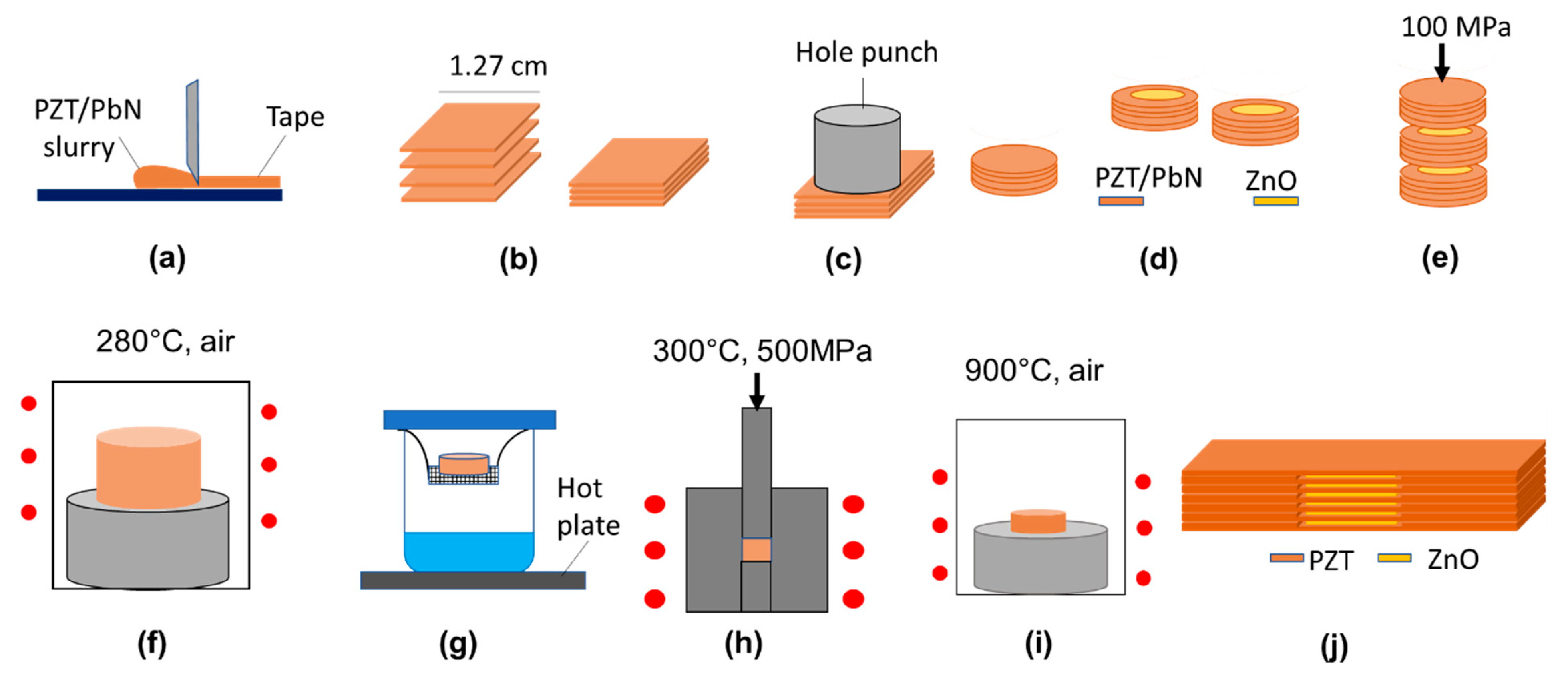
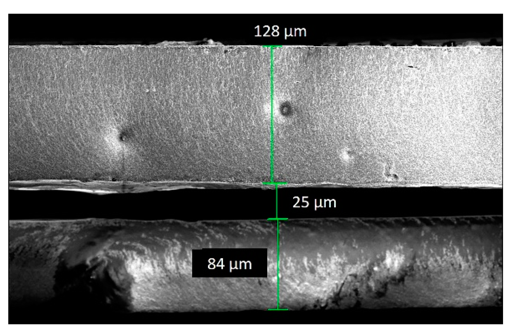
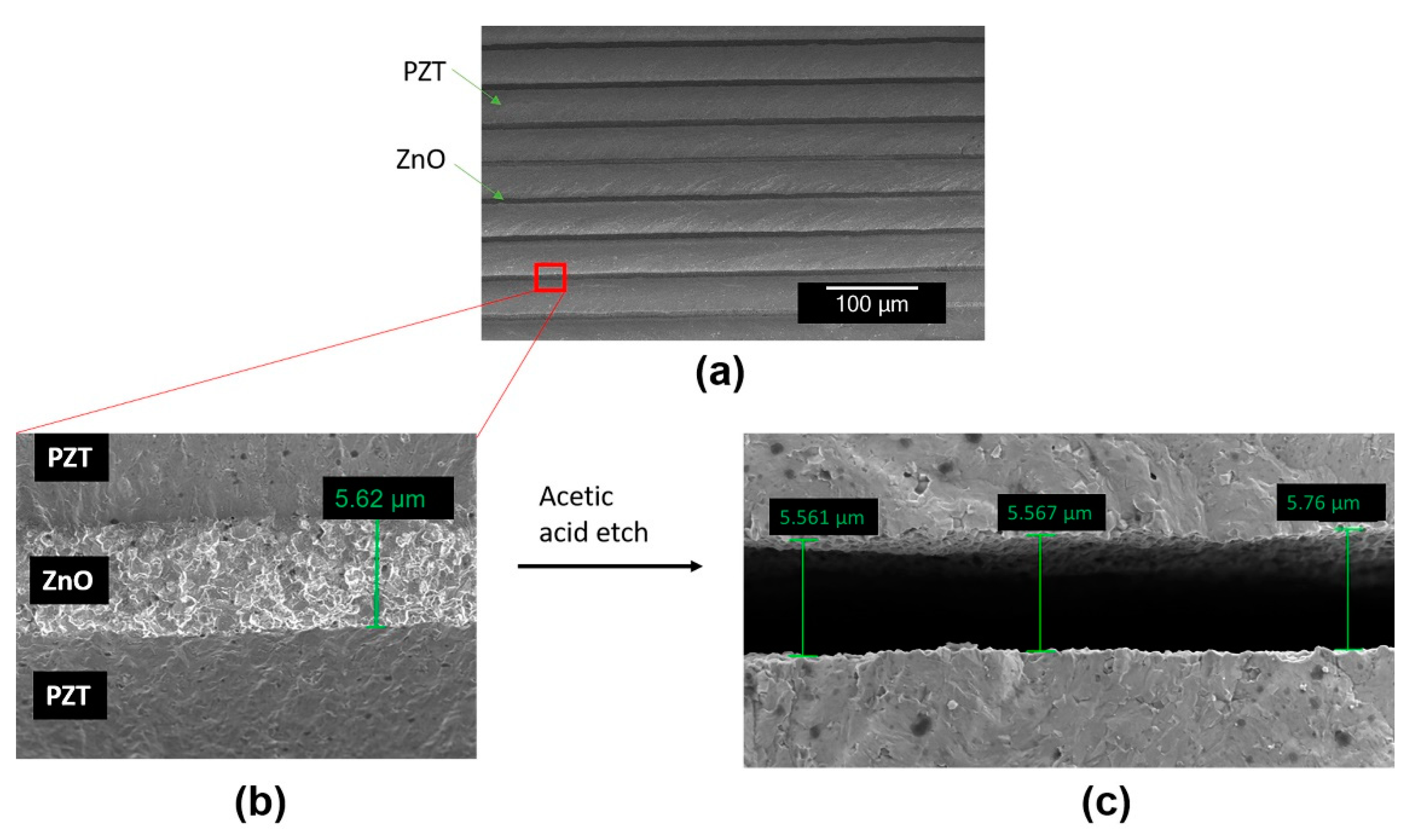
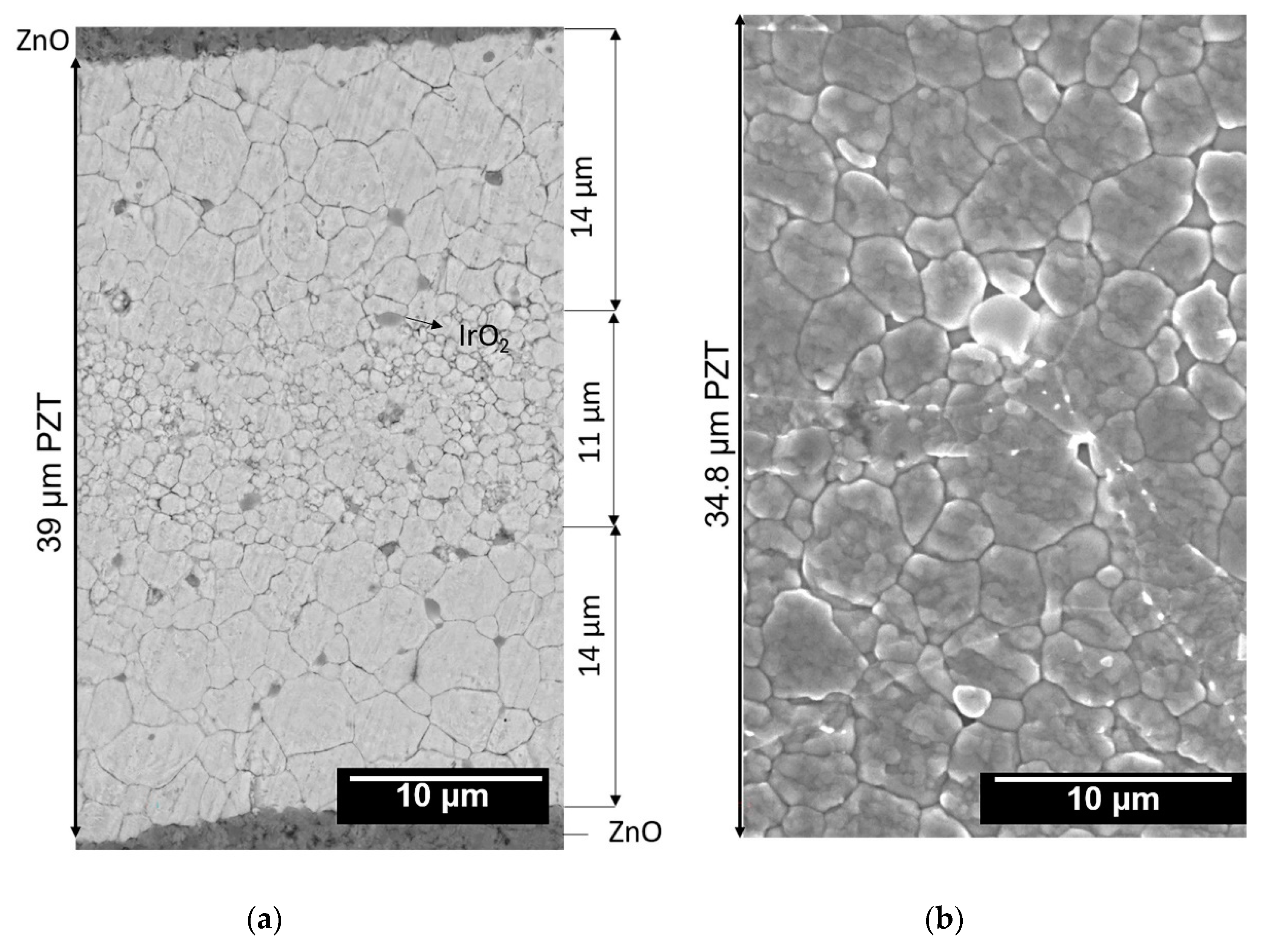
2.1. Design and Fabrication of PZT–ZnO 3-0 Composites

From the previously described design considerations, the dimensions of the final 2-2 composite to operate above 30 MHz were determined based on material constants shown in Table 2.
From Equations (1)–(3), for the transducer to operate at a center frequency >30 MHz, the width of the PZT elements and the kerfs should be 34 and 8 μm, respectively. Obtaining these fine features in the ceramic and polymer is beyond the capability of the dice-and-fill techniques, mandating an alternative approach for fabrication.
The forming process involves tape cast sheets of PZT/Pb nitrate with a sacrificial layer that can be stacked to form a 3-0 composite. The tape cast process helps maintain the uniformity in thickness of each element of the 2-2 composite. As an alternative, initial work was carried out using a 25 µm graphite foil as a thermally degraded sacrificial layer. The procedure for the fabrication of each of these samples is described in this section.
To begin, an attrition-milled PZT-5A nanopowder containing a bimodal distribution of particle sizes (50–300 nm) was utilized, as described elsewhere [66]. It is noted that there is no requirement for a bimodal distribution for the cold sintering process, though use of such a distribution produces better densification. A PZT-Pb nitrate slurry containing 40 vol% ceramic was prepared using a procedure described elsewhere [66]. The slurry was composed of 4 g PZT, 0.4 g (15 vol%) Pb nitrate, 2.76 g Vehicle A (95 wt % methyl ethyl ketone (MEK), 5 wt % polypropylene carbonate), 1.36 g Vehicle B (65 wt % MEK, 28 wt % polypropylene carbonate, and 7 wt % butyl benzyl phthalate), and 1 g MEK was added to adjust the viscosity of the slurry. This slurry was cast using a stationery Mylar (polypropylene) carrier film of ~76 µm thickness (Figure 1a). Mylar film provides flexibility in handling the tape, does not react with the tape and allows the tape to be easily peeled off. The doctor blade height was adjusted to 14 mil (~355 microns). After casting, the tape was allowed to dry in air for 4 h. The tape was then cut into square sheets with side 1.27 cm (0.5 inch). These square sheets were peeled off the Mylar and stacked, as illustrated in Figure 1b. Each stack served as an individual PZT element in the 2-2 composite. These stacks were then cut into circles using a cookie cutter or hole punch with 1.27 cm diameter. This process is illustrated in Figure 1c.
Graphite foils were cut into circles with diameter 0.635 cm (0.25 inch) and placed atop each PZT tape cast sheet concentrically, as shown in Figure 1d. The PZT stack containing the sacrificial layer was then placed into a stainless-steel die (Wartburg Tool & Die, Inc., Wartburg, TN, USA) with 1.27 cm diameter, with the layers parallel to the plungers. Lamination of this composite stack was carried out for 15 min at 70 °C by applying a 100 MPa uniaxial pressure on a Carver Model M press (Figure 1e). Uniaxial lamination compresses the tapes, tacking them together, and reducing the thickness of each layer [35]. The organics in the tapes were then burned out in a box furnace for 24 h by slowly ramping up the temperature (0.4 °C/min) to 280 °C in ambient air. This has previously been shown to enable effective binder burnout [67].
After the binder burn out process, a steaming process was carried out to reintroduce moisture in the sample. As seen in Figure 1g, steaming was carried out by hanging the sample in a beaker containing water at 120 °C. This process allowed the lead nitrate in the tapes to absorb the water vapor that condensed onto the sample. After steaming for 1.5 h, the sample was immediately loaded into the die for cold sintering (Figure 1h).
As described by Wang et al., the cold sinter-assisted densification process of PZT using Pb nitrate as a sintering aid involves 2 steps: (1) cold sintering (CSP) and (2) post annealing [59]. Following their work, CSP of the composite was carried out at 300 °C at 500 MPa for 3 h. Subsequently, the sample was post annealed in a box furnace. In order to remove the graphite foil, initially, a 1 °C/min ramp rate was used to reach 500 °C where the temperature was held for 30 min. The temperature was increased at a 5 °C/min ramp rate to 900 °C with a 3 h hold time (Figure 1i) [66]. Since graphite foil burns out at temperatures ~400 °C, the post anneal step leaves a kerf behind. The microstructure of one such kerf is shown in Figure 2. Good fidelity of the patterned feature is apparent. To achieve the geometries required for a higher frequency composite, thinner graphite foils would need to be employed.
As an alternative material for which the thickness of the kerf could be readily tailored, ZnO was also considered as a sacrificial layer. The process involves stacking tape cast sheets of ZnO between the PZT tapes to form a 3-0 composite (Figure 1). ZnO was chemically removed to form kerfs in the PZT ceramic. The width of the elements and the kerfs is dictated by the amount of shrinkage occurring in the PZT and ZnO layers respectively.
Several procedures have been established for tape casting ZnO [55]. In this case, however, the slurry was made with 15 g of ZnO (Acros Organics, Morris Plains, NJ, USA), 10 g Vehicle A, 8.4 g Vehicle B, and 10 g MEK to adjust the viscosity. For casting the slurry, the doctor blade height was adjusted to 7 mil (177.8 µm). After drying for 4 h, the ZnO tapes, 17–18 μm thick, were peeled off the Mylar film and cut into circular sheets with diameter 0.635 cm. Each ZnO sheet was then placed atop each PZT stack in a concentric manner, as shown in Figure 1d). The process is described in Figure 1. Samples containing 16 and 32 PZT elements were fabricated using this process.

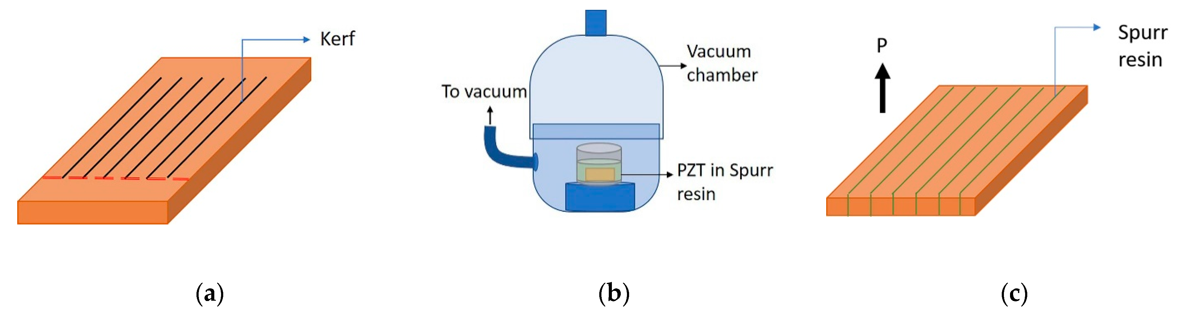
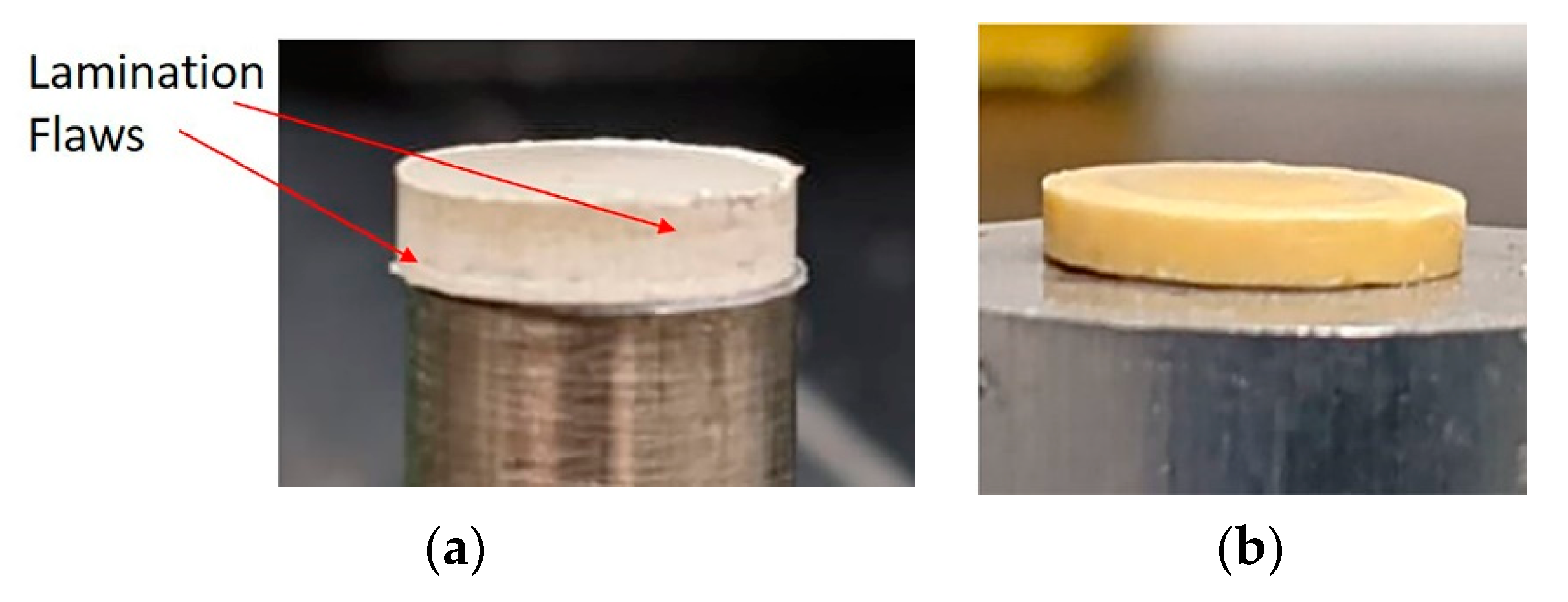
2.2. Fabrication and Characterization of PZT–Polymer 2-2 Composites

Two parallel cuts, 0.6 mm apart, were made in the densified composite sample using a wire saw (Princeton Scientific Tech, Easton, PA, USA) to obtain a 3-0 geometry as shown in Figure 1j. The cross section was fine polished in a Leica TXP polisher using lapping films of 9, 2, and 0.5 μm. PZT grain size measurement was made using a linear intercept method shown in Equation (4) [68]:
A v e r a g e   g r a i n   s i z e = 1.5 × t o t a l   l e n g t h   o f   l i n e s   ( μ m ) t o t a l   g r a i n   b o u n d a r y   c o u n t
To release the ZnO sacrificial layer, the sample was placed in a beaker containing 50% glacial acetic acid. To increase the ZnO etch rate, the acetic acid was heated to ~75 °C on a hot plate and the system was agitated using a magnetic stir bar. The process was carried out for 48–96 h to release the ZnO completely. The resulting geometry is shown in Figure 3a. The release of the ZnO was characterized using a scanning electron microscope (Apreo SEM, Thermo Fisher Scientific, Hillsboro, OR, USA) operated at 15 kV.
The sample was diced on one end as shown in Figure 3a. The kerfs left behind by the release of the ZnO layer were then backfilled by immersing the sample in Spurr resin in a vacuum chamber for 30 min (Figure 3b). The polymer was then cured overnight at 70 °C for 8 h. The excess epoxy was polished off the sample surfaces after which the sample was cut to obtain a 2-2 composite geometry, as shown in Figure 3c. The resulting microstructure was obtained using SEM.
In order to make quantitative measurements of the piezoelectric properties, the final dimensions of the composite must meet the requirements stipulated by the IEEE standard to avoid spurious modes. In the thickness extensional (kt) mode, the thickness of the overall composite should be 10 times smaller than the sample length or diameter, such that when operating in the thickness mode, the sample is clamped along the 1- and 2-directions [21]. The width of the sample can be 3 times smaller than the sample length. Thus, to comply with these requirements, the sample was diced, and lapped to a length of 3 mm, thickness of 110 microns and a width of 1 mm.

2.3. Electrical Characterization

The top and bottom faces of the sample in the orientation shown in Figure 3c were electroded by sputter depositing gold. The dielectric permittivity and loss tangents were measured using a Hewlett-Packard 4284A LCR meter (Agilent Technologies, Inc., Palo Alto, CA, USA). A system with a Trek Model 30/20 high voltage amplifier system (Trek, Inc., Lockport, NY, USA) and LabVIEW software (National Instruments Corporation, Austin, TX, USA) were used to measure the polarization-electric field hysteresis loops (P-E loops) at room temperature at a frequency at 10 Hz. The samples were DC poled at 70 °C at 2 times the coercive field (35 kV/cm [66]) for 1 h in the direction shown by the black arrow in Figure 3c.
For resonance frequency measurements, impedance analysis was carried out using Precision impedance analyzer (Agilent E4980A). The frequency measurement range was set to 100 kHz to 30 MHz. Piezoelectric coefficient (d33) and coupling coefficient (k33) were derived from the resonance and antiresonance frequencies. The piezoelectric coefficient d33 was also measured using a direct method with a d33 PiezoMeter system (PM 300, Piezotest Pte. Ltd., Singapore).

3. Results and Discussion

3.1. PZT–ZnO 3-0 Composite

Figure 4a shows a photograph of the 30-element sample after the binder burn out step. Lamination flaws are distinctly visible on the edge of the sample. However, these flaws are not seen in the sample after CSP (Figure 4b).
During CSP of PZT with moist Pb nitrate as a sintering aid, densification results in particle rearrangement assisted by a plastic deformation of Pb nitrate [66,69]. It is possible that the combination of particle rearrangement under uniaxial pressure and evaporation of water as the transient liquid phase helped mitigate the lamination flaws. In the post anneal step, as described by Wang et al., PbO (formed by the decomposition of Pb nitrate at ~400 °C) acts as a liquid phase at 900 °C and densification proceeds via a liquid phase sintering mechanism which leads to >97% relative densities in PZT. It must be noted that since no transient liquid phase such as acetic acid, was added to the ZnO tape cast sheets, densification of ZnO occurred only during the post anneal step.
Figure 5 shows a microstructure of a cross section of a 16 element PZT–ZnO 3-0 composite before and after etching ZnO. This process achieved a reasonable uniformity in the thickness of each layer.
The PZT and ZnO widths measured for the 16 and 32 element samples, are listed in Table 3. A 17 µm ZnO green tape cast sheet reduced to 5.4 µm upon densification in the sample with 32 elements. This corresponds to a ~68% shrinkage in each of the ZnO layers. Thus, to reach the desired thickness of ~34 µm, PZT tapes were stacked to ~112 µm thickness for each element. After densifying the composite, the thickness of these stacks reduced to ~35 µm (consistent with the previous observation of a ~68% shrinkage in the PZT layers).
It is notable that the cold sintering approach results in well-controlled geometries even of fine ceramic layers. There is no evidence for warping or distortion of the PZT elements that would complicate fabrication of a 2-2 ultrasound transducer, even at high resonant frequencies. Upon dicing and polishing the composite multiple times, the kerf dimensions remained uniform which is an advantage over other fabrication methods that tend to distort geometries upon firing. In comparison to the previous methods involving sacrificial layers, such as the work by Kwon and Zhang et al., this method provides a much higher fine-scale dimensional control on the PZT beams as well as the kerfs [35,36]. Indeed, increasing the green density of the ceramic is instrumental in improving the fidelity of the composite geometry.
The microstructures in Figure 6a,b show PZT grains in a polished cross section of the composite. For the PZT beams with thicknesses >35 μm, in the region up to 14 μm below and above the ZnO layers, the average grain size of the PZT was 4.3 μm (Figure 6a). In contrast, in areas further from the ZnO sacrificial layers, the average grain size of the PZT was 2 μm, leading to a bimodal distribution of the grain sizes in these PZT beams. In cases where the PZT beams were less than 35 μm thick, this bimodal distribution was absent, and the average grain size was 5.1 μm (Figure 6b). ZnO is known to enhance densification of PZT by acting as a liquid phase at 900 °C [70]. It is speculated that the ZnO serves as a liquid phase sintering aid that accelerates the grain growth adjacent to the PZT–ZnO interface. When the thickness of the PZT layer was reduced (<35 μm), the ZnO/PZT ratio increased, thereby increasing the amount of liquid phase available for sintering at 900 °C, leading to more extensive grain growth. However, it is likely that during the process, Zn also partially replaces the B-site cation (Zr4+/Ti4+) in PZT due to comparable ionic radii [71]. As a result, PZT becomes acceptor doped and oxygen vacancies are created according to Equation (5) or (6), depending on the amount of residual lead oxide.
ZnO   PZT   Zn Zr / Ti + 2 V o +   V Pb +   O O ×
PbO + ZnO   PZT   Pb Pb × +   Zn Zr / Ti +   V o + 2 O O ×

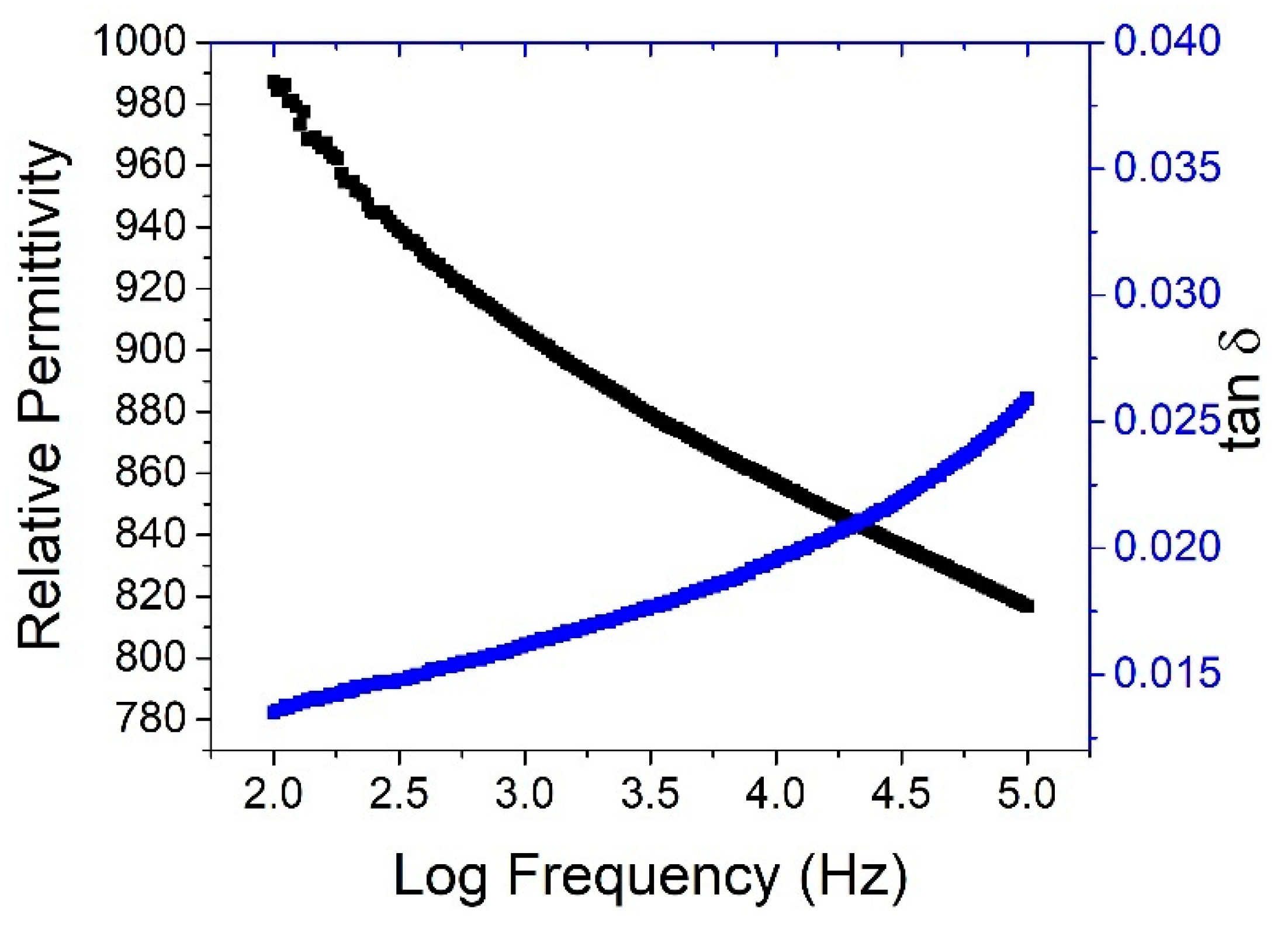
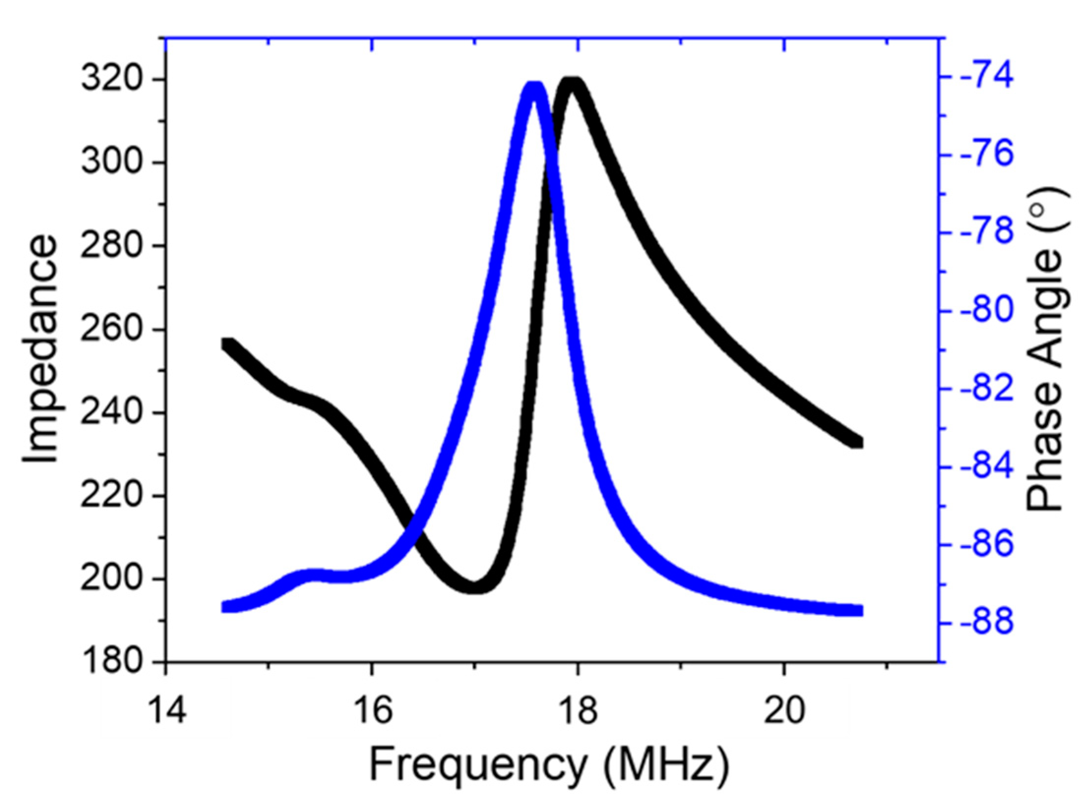
3.2. Electrical Measurements

The PZT–polymer 2-2 composite was polished to thickness. For ease of handling a thickness of 110 μm was chosen to enable a resonance frequency of ~17 MHz. The kerf dimensions would allow thinner, higher frequency composites, but such thin parts were fragile. The parts were electroded on the top and bottom faces, as shown in Figure 3c, such that the PZT and polymer were connected in parallel. Using the mixing rule for parallel connectivity, the dielectric constant of the composite ( ε r c o m p ) can be calculated using Equation (7) [72]. The relative permittivity value of Zn-doped PZT ( ε r P Z T ) was taken from Reference 70 as an estimate. The relative permittivity of Spurr resin ( ε r p o l y m e r ), 2.1, was measured at 1 kHz at room temperature. Volume fractions of the electroded parts of PZT ( V P Z T ) and polymer ( V p o l y m e r ) were evaluated, the estimated relative permittivity of the composite ε r c o m p was 1020.
ε r c o m p = ( V P Z T ε r P Z T + V p o l y m e r ε r p o l y m e r )
ε r c o m p = ( 1200 0.85 + 2.1 0.15 ) ε r c o m p = 1020
Figure 7 shows the relative permittivity as a function of frequency; it was found that the relative permittivity dropped as a function of frequency from ~987 to ~816. The dielectric loss obtained at 1 kHz was as low as 0.013. It is apparent that the measured permittivity is slightly below that of the capacitor in parallel model. The reduced permittivity could be due to: ZnO in grain boundaries in some of the PZT layer, reducing its effective permittivity, acceptor doping of the PZT which drops its effective permittivity, or imperfect alignment of the electrodes with respect to the kerfs.
The samples were poled at 20 kV/cm at room temperature. The resulting d33 was 122 pC/N using the Berlincourt method. It is well known that acceptor doping of PZT results in lower values of d33 compared to their soft doped counterparts. Typical values of hard doped PZT, such as PZT-4 and PZT-8 (Boston Piezo Optics) are 295 pC/N and 225 pC/N, respectively (# Manufacturer reported values (https://www.bostonpiezooptics.com/ceramic-materials-pzt, accessed on 1 February 2021). A lower value of d33 could result from insufficient poling or the presence of ZnO in the grain boundaries.
Figure 8 shows resonance and anti-resonance frequency for the 2-2 composites. As stated earlier, only the thickness mode (33-mode) should be excited for a transducer array. The third set of harmonics will represent the 33-mode. The thickness mode frequency constant for an acceptor doped PZT is 1882 Hz-m [11]. Therefore, the sample thickness must be ~53 µm for the fundamental thickness mode resonance to occur at a frequency >30 MHz. In this work, however, since the sample thickness was 110 µm, the resonance frequency is expected to occur at 17.1 MHz.
Typical coupling coefficient k33 values for a hard doped PZT are 0.64–0.7 (* Manufacturer reported values (https://www.bostonpiezooptics.com/ceramic-materials-pzt accessed on 18 August 2021)). As shown in Figure 8, the resonance and antiresonance frequencies obtained were 17.01 and 17.94 MHz, respectively. The coefficient kt was derived from these resonance ( f r ) and antiresonance ( f a ) frequencies using the following Equation [20]:
k t 2 =   π 2 × f r f a × cot π 2 ( f r f a )
k t = 0.35
The open circuit stiffness ( c 33 D ) is given by Equation (9) which was used to derive the short circuit stiffness ( c 33 E ) , as shown in Equation (9) [20]:
c 33 D = 4 π f a 2 t 2
c 33 D = 4.9 × 10 10   P a
c 33 E = c 33 D ( 1 k t 2 )
c 33 E = 4.3   × 10 10   P a
where, t is the thickness of the composite.
The coefficient k t had a comparatively low value, perhaps due to insufficient poling. This is also suggested by the small (12°) phase change in the impedance spectra. When poled at higher electric fields, the composite was subject to dielectric breakdown. This behavior might be tied to either an excess amount of acceptor doping generating a larger amount of oxygen vacancies in PZT, or the presence of ZnO at the grain boundaries of reducing coupling between the PZT grains.

4. Conclusions

The cold sintering process designed for PZT with Pb nitrate as a sintering aid can be extended to facilitate the fabrication of multilayer composite structures with stable geometries. Tape casting produces flat, well-defined kerfs and beams with tailorable thicknesses. In this work, PZT–ZnO and PZT-graphite composites were successfully cold sintered, then post-annealed to produce well-controlled geometries, without significant warping of the ceramic part. Cold sintering helped mitigate the lamination flaws in the PZT–ZnO composites. The ZnO sacrificial layer produced composite geometries that can be scaled to produce a high frequency array transducer. This method provided a novel pathway to develop composite geometries with high fidelity and to overcome the processing challenges posed by some previously used techniques. It is noted that the process is not specific to the use of ZnO; any material that can be cold sintered with PZT, which is thermally stable to 900 °C, and which is readily removed chemically could be used.
It was found that the ZnO sacrificial layer also acted as a liquid phase sintering aid during the post anneal process, which led to grain growth in PZT while acceptor doping the adjacent PZT. The permittivity and loss tangents in the PZT polymer 2-2 composites closely matched the theoretical values obtained by using a parallel mixing rule. The resonance frequency of the composite was >17 MHz. If the thickness of the overall composite is lowered, it is possible to increase the resonance frequency >30 MHz. The derived coupling coefficient and d33 value obtained were lower than expected, possibly due to a larger amount of acceptor doping in the PZT. In the future, additional characterization must be carried out in order to determine the main cause for the degradation of the electrical properties.

Author Contributions

Conceptualization, S.G. and S.T.-M.; Data Curation, S.G.; Formal Analysis, S.G. and S.T.-M.; Funding Acquisition, S.T.-M.; Investigation, S.G. and A.M.; Methodology, S.G., S.S., A.M. and S.T.-M.; Project Administration, S.T.-M.; Resources, D.W., A.M. and S.D.; Supervision, S.T.-M.; Validation, S.G. and S.T.-M.; Visualization, S.G.; Writing—Original Draft, S.G.; Writing—Review and Editing, S.G., C.A.R. and S.T.-M. All authors have read and agreed to the published version of the manuscript.

Funding

This material is based upon work supported by the National Science Foundation, as part of the Center for Dielectrics and Piezoelectrics under Grant Nos. IIP-1841453 and IIP-1841466.

Institutional Review Board Statement

Not applicable.

Informed Consent Statement

Not applicable.

Data Availability Statement

Data are available on reasonable request from the corresponding author.

Acknowledgments

The authors would like to thank the Center for Dielectrics and Piezoelectrics for funding this work as well as for the inputs received from its members. The authors would like to thank Tianning Liu and Andy Fitzgerald for useful discussions on the release of ZnO. The authors appreciate the help of the Materials Characterization Lab for their useful inputs, in particular, Julie Anderson and Wes Auker for their help with SEM analysis, Maria DiCola for her help with sample preparation and Jeff Long for his help with the impedance measurements.

Conflicts of Interest

The authors declare no conflict of interest. The funders had no role in the design of the study; in the collection, analyses, or interpretation of data; in the writing of the manuscript, or in the decision to publish the results.

References

  1. Shung, K.K. Diagnostic ultrasound: Past, present, and future. J. Med. Biol. Eng. 2011, 31, 371–374. [Google Scholar] [CrossRef]
  2. Shung, K.K. High frequency ultrasonic imaging. J. Med. Ultrasound 2009, 17, 25–30. [Google Scholar] [CrossRef] [Green Version]
  3. Szabo, T.L.; Lewin, P.A. Ultrasound transducer selection in clinical imaging practice. J. Ultrasound Med. 2013, 32, 573–582. [Google Scholar] [CrossRef]
  4. Jiang, X.; Snook, K.; Walker, T.; Portune, A.; Haber, R.; Geng, X.; Welter, J.; Hackenberger, W.S. Single crystal piezoelectric composite transducers for ultrasound NDE applications. Int. Soc. Opt. Photonics 2008, 6934, 69340D. [Google Scholar] [CrossRef]
  5. Shung, K.K. Diagnostic Ultrasound: Imaging and Blood Flow Measurements; CRC Press: Boca Raton, FL, USA, 2015. [Google Scholar] [CrossRef]
  6. Song, L.; Maslov, K.I.; Bitton, R.; Shung, K.K.; Wang, L.V. Fast 3-D dark-field reflection-mode photoacoustic microscopy in vivo with a 30-MHz ultrasound linear array. J. Biomed. Opt. 2008, 13, 054028. [Google Scholar] [CrossRef]
  7. Giannelli, P.; Bulletti, A.; Capineri, L. Multifunctional piezopolymer film transducer for structural health monitoring applications. IEEE Sens. J. 2017, 17, 4583–4586. [Google Scholar] [CrossRef]
  8. Smith, W.A. Piezocomposite materials for acoustical imaging transducers. In Acoustical Imaging; Jones, J.P., Ed.; Springer: Boston, MA, USA, 1995; pp. 121–138. [Google Scholar] [CrossRef]
  9. Lockwood, G.R.; Turnbull, D.H.; Christopher, D.A.; Foster, F.S. Beyond 30 MHz [applications of high-frequency ultrasound imaging]. IEEE Eng. Med. Biol. Mag. 1996, 15, 60–71. [Google Scholar] [CrossRef]
  10. Passmann, C.; Ermert, H. A 100-MHz ultrasound imaging system for dermatologic and ophthalmologic diagnostics. IEEE Trans. Ultrason. Ferroelectr. Freq. Control 1996, 43, 545–552. [Google Scholar] [CrossRef]
  11. Mina, I.G. High Frequency Transducers from PZT Thin Films. Master’s Thesis, Pennsylvania State University, University Park, PA, USA, 2007. [Google Scholar]
  12. Safari, A. Development of piezoelectric composites for transducers. J. Phys. III 1994, 4, 1129–1149. [Google Scholar] [CrossRef]
  13. Newnham, R.E.; Skinner, D.P.; Cross, L.E. Connectivity and piezoelectric-pyroelectric composites. Mater. Res. Bull. 1978, 13, 525–536. [Google Scholar] [CrossRef]
  14. Newnham, R.E. Composite electroceramics. Ferroelectrics 1986, 68, 1–32. [Google Scholar] [CrossRef]
  15. Turnbull, D.H.; Foster, F.S. Beam steering with pulsed two-dimensional transducer arrays. IEEE Trans. Ultrason. Ferroelectr. Freq. Control 1991, 38, 320–333. [Google Scholar] [CrossRef]
  16. Gururaja, T.R.; Schulze, W.A.; Cross, L.E.; Newnham, R.E.; Auld, B.A.; Wang, Y.J. Piezoelectric composite materials for ultrasonic transducer applications. Part I: Resonant modes of vibration of PZT rod-polymer composites. IEEE Trans. Sonics Ultrason. 1985, 32, 481–498. [Google Scholar] [CrossRef] [Green Version]
  17. Akdogan, E.K.; Allahverdi, M.; Safari, A. Piezoelectric composites for sensor and actuator applications. IEEE Trans. Ultrason. Ferroelectr. Freq. Control 2005, 52, 746–775. [Google Scholar] [CrossRef]
  18. Jaffe, B.; Cook, W.R., Jr.; Jaffe, H. Piezoelectric Ceramics; Academic Press: London, UK; New York, NY, USA, 1971. [Google Scholar]
  19. Corker, D.; Whatmore, R.; Ringgaard, E.; Wolny, W. Liquid-phase sintering of PZT ceramics. J. Eur. Ceram. Soc. 2000, 20, 2039–2045. [Google Scholar] [CrossRef]
  20. International Standard: IEEE Standards on Piezoelectricity, ANSI/IEEE Std 176–1987; The Institute of Electrical and Electronics Engineers, Inc.: Manhattan, NY, USA, 1987; p. 66. [CrossRef]
  21. Cain, M.G.; Stewart, M. Measurement Good Practice Guide No. 33. Piezoelectric Resonance 2001. Available online: https://www.npl.co.uk/special-pages/guides/gpg33_resonance.aspx?ext= (accessed on 5 March 2021).
  22. Ritter, T.A.; Shrout, T.R.; Tutwiler, R.; Shung, K.K. A 30-MHz piezo-composite ultrasound array for medical imaging applications. IEEE Trans. Ultrason. Ferroelectr. Freq. Control 2002, 49, 217–230. [Google Scholar] [CrossRef]
  23. Lee, H.J.; Zhang, S. Design of low-loss 1-3 piezoelectric composites for high-power transducer applications. IEEE Trans. Ultrason. Ferroelectr. Freq. Control 2012, 59, 1969–1975. [Google Scholar] [CrossRef]
  24. Hayward, G.; Bennett, J. Assessing the influence of pillar aspect ratio on the behavior of 1-3 connectivity composite transducers. IEEE Trans. Ultrason. Ferroelectr. Freq. Control 1996, 43, 98–108. [Google Scholar] [CrossRef]
  25. Wang, S.H.; Tsai, M.C. Dynamic modeling of thickness-mode piezoelectric transducer using the block diagram approach. Ultrasonics 2011, 51, 617–624. [Google Scholar] [CrossRef] [PubMed]
  26. Ikeda, T. Fundamentals of Piezoelectricity; Oxford University Press: Oxford, UK, 1996. [Google Scholar]
  27. Klicker, K.A.; Newnham, R.E.; Cross, L.E.; Biggers, J.V. PZT Composite and A Fabrication Method Thereof. U.S. Patent 4,412,148, 25 October 1983. [Google Scholar]
  28. Sliwa, J.W.; Ayter, S.; Mohr, J.P., III. Acuson Corp, Method for Making Piezoelectric Composites. U.S. Patent 5,239,736, 31 August 1993. [Google Scholar]
  29. Savakus, H.P.; Klicker, K.A.; Newnham, R.E. PZT-epoxy piezoelectric transducers: A simplified fabrication procedure. Mater. Res. Bull. 1981, 16, 677–680. [Google Scholar] [CrossRef]
  30. Cannata, J.M.; Williams, J.A.; Zhou, Q.; Ritter, T.A.; Shung, K.K. Development of a 35-MHz piezo-composite ultrasound array for medical imaging. IEEE Trans. Ultrason. Ferroelectr. Freq. Control 2006, 53, 224–236. [Google Scholar] [CrossRef]
  31. Safari, A.; Janas, V.F. Processing of fine-scale piezoelectric ceramic/polymer composites for transducer applications. Ferroelectrics 1997, 196, 187–190. [Google Scholar] [CrossRef]
  32. Günther, P.A.; Neumeister, P.; Neubert, H.; Gebhardt, S. Development of 40-MHz ultrasonic transducers via soft mold process. IEEE Trans. Ultrason. Ferroelectr. Freq. Control 2019, 66, 1497–1503. [Google Scholar] [CrossRef]
  33. Safari, A.; Janas, V.; Panda, R.K. Fabrication of fine-scale 1-3 Pb(Zrx,Ti1−x)O3/ceramic/ polymer composites using a modified lost mold method. Int. Soc. Opt. Photonics 1996, 2721, 251–262. [Google Scholar] [CrossRef]
  34. Hackenberger, W.; Pan, M.J.; Kuban, D.; Ritter, T.; Shrout, T. Novel method for producing high frequency 2-2 composites from PZT ceramic. IEEE Int. Ultrason. Symp. Proc. 2000, 2, 969–972. [Google Scholar] [CrossRef]
  35. Kwon, S.; Hackenberger, W.; Rehrig, P.; Snook, K.; Rhee, S.; Shrout, T.R.; Geng, X. Ceramic/polymer 2-2 composites for high frequency transducers by tape casting. IEEE Symp. Ultrason. 2003, 1, 366–369. [Google Scholar] [CrossRef]
  36. Zhang, Y.; Jiang, Y.; Lin, X.; Xie, R.; Zhou, K.; Button, T.W.; Zhang, D. Fine-scaled piezoelectric ceramic/polymer 2-2 composites for high-frequency transducer. J. Am. Ceram. Soc. 2014, 97, 1060–1064. [Google Scholar] [CrossRef]
  37. Stevenson, J.W.; Reidmeyer, M.R.; Huebner, W. Fabrication and characterization of PZT/thermoplastic polymer composites for high-frequency phased linear arrays. J. Am. Ceram. Soc. 1994, 77, 2481–2484. [Google Scholar] [CrossRef]
  38. Livneh, S.S.; Janas, V.F.; Safari, A. Development of fine scale PZT ceramic fiber/polymer shell composite transducers. J. Am. Ceram. Soc. 1995, 78, 1900–1906. [Google Scholar] [CrossRef]
  39. Ohara, Y.; Miyayama, M.; Koumoto, K.; Yanagida, H. PZT-polymer composites fabricated with YAG laser cutter. Sens. Actuators A Phys. 1994, 40, 187–190. [Google Scholar] [CrossRef]
  40. Ohara, Y.; Miyayama, M.; Koumoto, K.; Yanagida, H. Partially stabilized zirconia-polymer composites fabricated with an ultrasonic cutter. J. Mater. Sci. Lett. 1993, 12, 1279–1282. [Google Scholar] [CrossRef]
  41. Hoy, C.V.; Barda, A.; Griffith, M.; Halloran, J.W. Microfabrication of ceramics by co-extrusion. J. Am. Ceram. Soc. 1998, 81, 152–158. [Google Scholar] [CrossRef]
  42. Lubitz, K.; Wolff, A.; Preu, G.; Stoll, R.; Schulmeyer, B. PcI2: New piezoelectric composites for ultrasonic transducers. Ferroelectrics 1992, 133, 21–26. [Google Scholar] [CrossRef]
  43. Zhou, Q.; Lau, S.; Wu, D.; Shung, K.K. Piezoelectric films for high frequency ultrasonic transducers in biomedical applications. Prog. Mater. Sci. 2011, 56, 139–174. [Google Scholar] [CrossRef] [PubMed] [Green Version]
  44. Safari, A.; Allahverdi, M.; Akdogan, E.K. Solid freeform fabrication of piezoelectric sensors and actuators. Front. Ferroelectr. 2006, 41, 177–198. [Google Scholar] [CrossRef]
  45. Zhen, Y.; Li, J.F. Preparation and electrical properties of fine-scale 1–3 lead zirconium titanate/epoxy composite thick films for high-frequency ultrasonic transducers. J. Appl. Phys. 2008, 103, 084119. [Google Scholar] [CrossRef]
  46. Lee, H.J.; Zhang, S.; Bar-Cohen, Y.; Sherrit, S. High temperature, high power piezoelectric composite transducers. Sensors 2014, 14, 14526–14552. [Google Scholar] [CrossRef] [Green Version]
  47. Chabok, H.; Zhou, C.; Chen, Y.; Eskandarinazhad, A.; Zhou, Q.; Shung, K. Ultrasound transducer array fabrication based on additive manufacturing of piezocomposites. In Proceedings of the International Symposium on Flexible Automation, St. Louis, MO, USA, 18–20 June 2012; Volume 45110, pp. 433–444. [Google Scholar] [CrossRef]
  48. Hackenberger, W.S.; Kim, N.; Randall, C.A.; Cao, W.; Shrout, T.R.; Pickrell, D.P. Processing and structure-property relationships for fine grained PZT ceramics. In Proceedings of the Tenth IEEE International Symposium on Applications of Ferroelectrics, ISAF’96, East Brunswick, NJ, USA, 18–21 August 1996; Volume 2, pp. 903–906. [Google Scholar] [CrossRef]
  49. Zhou, W.; Zhang, T.; Ou-Yang, J.; Yang, X.; Wu, D.; Zhu, B. PIN-PMN-PT single crystal 1-3 composite-based 20 MHz ultrasound phased array. Micromachines 2020, 11, 524. [Google Scholar] [CrossRef]
  50. Bowen, L.J.; Gentilman, R.L.; Pham, H.T.; Fiore, D.F.; French, K.W. Injection molded fine-scale piezoelectric composite transducers. In Proceedings of the 1993 Proceedings IEEE Ultrasonics Symposium, Baltimore, MD, USA, 31 October–3 November 1993; pp. 499–503. [Google Scholar] [CrossRef]
  51. Cesarano, J., III; Calvert, P.D. National Technology, Engineering Solutions of Sandia LLC. Freeforming Objects with Low-Binder Slurry. U.S. Patent 6,027,326, 22 February 2000. [Google Scholar]
  52. Rittenmyer, K.; Shrout, T.; Schulze, W.A.; Newnham, R.E. Piezoelectric 3–3 composites. Ferroelectrics 1982, 41, 189–195. [Google Scholar] [CrossRef]
  53. Pan, M.-J.; Randall, C.A. A brief introduction to ceramic capacitors. IEEE Electr. Insul. Mag. 2010, 26, 44–50. [Google Scholar] [CrossRef]
  54. Lee, W.; Lyon, C.K.; Seo, J.H.; Lopez-Hallman, R.; Leng, Y.; Wang, C.Y.; Hickner, M.A.; Randall, C.A.; Gomez, E.D. Ceramic–salt composite electrolytes from cold sintering. Adv. Funct. Mater. 2019, 29, 1807872. [Google Scholar] [CrossRef]
  55. Funahashi, S.; Guo, H.; Guo, J.; Baker, A.L.; Wang, K.; Shiratsuyu, K.; Randall, C.A. Cold sintering and co-firing of a multilayer device with thermoelectric materials. J. Am. Ceram. Soc. 2017, 100, 3488–3496. [Google Scholar] [CrossRef]
  56. Baker, A.; Guo, H.; Guo, J.; Randall, C.A. Utilizing the cold sintering process for flexible–printable electroceramic device fabrication. J. Am. Ceram. Soc. 2016, 99, 3202–3204. [Google Scholar] [CrossRef]
  57. Guo, J.; Guo, H.; Baker, A.L.; Lanagan, M.T.; Kupp, E.R.; Messing, G.L.; Randall, C.A. Cold sintering: A paradigm shift for processing and integration of ceramics. Angew. Chem. 2016, 128, 11629–11633. [Google Scholar] [CrossRef]
  58. Ndayishimiye, A.; Sengul, M.Y.; Sada, T.; Dursun, S.; Bang, S.H.; Grady, Z.A.; Tsuji, K.; Funahashi, S.; van Duin, A.C.; Randall, C.A. Roadmap for densification in cold sintering: Chemical pathways. Open Ceram. 2020, 2, 100019. [Google Scholar] [CrossRef]
  59. Wang, D.; Guo, H.; Morandi, C.S.; Randall, C.A.; Trolier-McKinstry, S. Cold sintering and electrical characterization of lead zirconate titanate piezoelectric ceramics. APL Mater. 2018, 6, 016101. [Google Scholar] [CrossRef] [Green Version]
  60. Linder, V.; Gates, B.D.; Ryan, D.; Parviz, B.A.; Whitesides, G.M. Water-soluble sacrificial layers for surface micromachining. Small 2005, 1, 730–736. [Google Scholar] [CrossRef]
  61. Peeni, B.A.; Lee, M.L.; Hawkins, A.R.; Woolley, A.T. Sacrificial layer microfluidic device fabrication methods. Electrophoresis 2006, 27, 4888–4895. [Google Scholar] [CrossRef]
  62. Lee, J.D. Concise Inorganic Chemistry, 5th ed.; John Wiley & Sons: Hoboken, NJ, USA, 2008. [Google Scholar]
  63. Liu, T.; Wallace, M.; Trolier-McKinstry, S.; Jackson, T.N. High-temperature crystallized thin-film PZT on thin polyimide substrates. J. Appl. Phys. 2017, 122, 164103. [Google Scholar] [CrossRef] [Green Version]
  64. Gonzalez, J.; Marquina, J.; Rodriguez, F.; Valiente, R. Nanocrystals of ZnO formed by the hot isostatic pressure method. High Press. Res. 2009, 29, 594–599. [Google Scholar] [CrossRef]
  65. Butt, Z.; Pasha, R.A.; Qayyum, F.; Anjum, Z.; Ahmad, N.; Elahi, H. Generation of electrical energy using lead zirconate titanate (PZT-5A) piezoelectric material: Analytical, numerical and experimental verifications. J. Mech. Sci. Technol. 2016, 30, 3553–3558. [Google Scholar] [CrossRef] [Green Version]
  66. Wang, D. Low Temperature Processing of Electro-Ceramic Materials and Devices. Ph.D. Thesis, Pennsylvania State University, University Park, PA, USA, 2020. [Google Scholar]
  67. Guo, J.; Pfeiffenberger, N.; Beese, A.; Rhoades, A.; Gao, L.; Baker, A.; Wang, K.; Bolvari, A.; Randall, C.A. Cold sintering Na2Mo2O7 ceramic with poly (ether imide)(PEI) polymer to realize high-performance composites and integrated multilayer circuits. ACS Appl. Nano Mater. 2018, 1, 3837–3844. [Google Scholar] [CrossRef]
  68. ASTM E112-13, Standard Test Methods for Determining Average Grain Size; ASTM International: West Conshohocken, PA, USA, 2013; Available online: http://www.astm.org (accessed on 1 September 2018).
  69. Wang, D.; Dursun, S.; Gao, L.; Morandi, C.S.; Randall, C.A.; Trolier-McKinstry, S. Fabrication of bimorph lead zirconate titanate thick films on metal substrates via the cold sintering-assisted process. Acta Mater. 2020, 195, 482–490. [Google Scholar] [CrossRef]
  70. Banerjee, A.; Bandyopadhyay, A.; Bose, S. Influence of La2O3, SrO, and ZnO addition on PZT. J. Am. Ceram. Soc. 2006, 89, 1594–1600. [Google Scholar] [CrossRef]
  71. Trolier-McKinstry, S.; Newnham, R.E. Materials Engineering: Bonding, Structure, and Structure-Property Relationships; Cambridge University Press: Cambridge, UK, 2018. [Google Scholar]
  72. Wu, Y.; Zhao, X.; Li, F.; Fan, Z. Evaluation of mixing rules for dielectric constants of composite dielectrics by MC-FEM calculation on 3D cubic lattice. J. Electroceramics 2003, 11, 227–239. [Google Scholar] [CrossRef]
Figure 1. Fabrication process sequence for 3-0 PZT-sacrificial layer composites. The figures illustrate the following 10 steps: (a) casting PZT/Pb nitrate slurry into a tape; (b) cutting into squares with side 1.27 cm; (c) stacking square sheets and cutting stack into circular sheets with a hole punch; (d) placing sacrificial layer concentrically on the PZT tape stack; (e) uniaxially laminating at 100 MPa; (f) burning out the binder from the composite stack in a box furnace; (g) hanging sample in a beaker on a hot plate for steaming; (h) cold sintering composite sample in a die; (i) post annealing sample in a box furnace; (j) dicing post annealed sample to expose the sacrificial layers. The temperature profile for the 2-step densification of the ceramic is shown in (k).
Actuators 10 00235 g001aActuators 10 00235 g001b
Figure 2. Microstructure of a kerf created by the release of the graphite foil during the post anneal step.
Actuators 10 00235 g002
Figure 3. Illustration of the process to fabricate PZT–polymer 2-2 composite. (a) Shows the kerfs formed in PZT after etching the ZnO layers. The sample was diced along the red dotted lines marked on the PZT. (b) Illustrates the epoxy backfilling process. (c) Shows the 2-2 composite prepared after backfilling it with Spurr resin and polishing. The black arrow in (c) shows the poling direction.
Actuators 10 00235 g003
Figure 4. PZT–ZnO 3-0 composite placed on a metal cylinder after (a) the binder burn out step containing lamination defects, and (b) after the cold sintering step.
Actuators 10 00235 g004
Figure 5. Cross section of a 16 element PZT–ZnO 3-0 composite after the post anneal step, demonstrating uniformity in thickness along the length of the composite showing: (a) the multiple layers of PZT and ZnO; (b,c) magnified microstructure of the composite showing the thickness of the ZnO layer (b) before and (c) after etching with acetic acid. The surface roughness of the kerf region is on a submicron length scale, which is expected to be reasonable for high frequency 2-2 composites.
Actuators 10 00235 g005
Figure 6. SEM microstructures of polished cross sections of the PZT layers in (a) 16 element and (b) 32 element composites: (a) 39 μm thick PZT beam; (b) 34.8 μm thick PZT beam. The samples were coated with iridium prior to imaging. The dark grains in the PZT beam in (a) are oxidized IrO2.
Actuators 10 00235 g006
Figure 7. Relative permittivity of the 30 element PZT–polymer 2-2 composite as a function of log of frequency.
Actuators 10 00235 g007
Figure 8. Impedance spectra of PZT–polymer 2-2 composite containing 32 elements.
Actuators 10 00235 g008
Table 1. Advantages and disadvantages of common composite transducer processing methods.
Dice and FillInjection MoldingSolid Freeform
Fabrication
Lost Mold
Technique
AdvantagesCan achieve kerfs above 12 µm.
Utilizes inexpensive
tooling.
Rapid production and flexibility in transducer design.Can process different shapes.
Overcomes problems with dimensional tolerances.
Can be used to fabricate 30 µm beam sizes with 10 µm kerfs.
DisadvantagesFails for arrays >~10–20 MHz.
Piezoelectric elements can crack at very low widths. Limited element patterns.
Requires expensive precision molds.
Ceramic green body is prone to deformation on sintering.
Limited in fine feature sizes and achievable densities.At very fine feature sizes, the structure deforms upon firing.
Table 2. Material properties used to determine dimensions of the ceramic–polymer 2-2 composite using Equations (1)–(3).
PZTPolymer
TypePZT-5A
(PKI-509, PiezoKinetics Inc., Bellefonte, PA, UK)
Spurr resin
(Polyscience Inc., Warrington, PA, UK)
C 11 E (GPa)121 Ref. [65]5.28 Ref. [23]
Density (kg/m3) 76001135
Velocity (m/s) c l = 3938 c s = 976 Ref. [23]
Width (µm)≤34≤8
Manufacturer reported values.
Table 3. PZT and ZnO width measurements for the 2-2 composites containing 16 and 32 PZT beams.
LayerGreen Tape Thickness (μm)Layer Width (μm)Standard Deviation in Layer Width
16 elementsPZT125390.7
ZnO/kerf175.40.2
32 elementsPZT112351.1
ZnO/kerf196.20.3
Publisher’s Note: MDPI stays neutral with regard to jurisdictional claims in published maps and institutional affiliations.

