

Development of Novel Hydraulic 3D Printed Actuator Using Electrorheological Fluid for Robotic Endoscopy

Mannheim Institute for Intelligent Systems in Medicine, Ruprecht-Karls University Heidelberg, 68167 Mannheim, Germany
*
Author to whom correspondence should be addressed.
Actuators 2024, 13(4), 119; https://0-doi-org.brum.beds.ac.uk/10.3390/act13040119
Submission received: 26 February 2024
/
Revised: 19 March 2024
/
Accepted: 21 March 2024
/
Published: 23 March 2024
(This article belongs to the Special Issue Soft Actuators for Medical Robotics)
Abstract
:Endoscopy has made a significant and noteworthy contribution to the field of medical science and technology. Nevertheless, its potential remains constrained due to the limited availability of rigid or flexible endoscopes. This paper introduces a novel hydraulic actuator based on electrorheological fluid (ERF) as a pivotal advancement in bridging the existing gap within the realm of endoscopy. Following a comprehensive introduction that briefly outlines the electrorheological effect, the subsequent section is dedicated to the elucidation of the actuator’s development process. Challenges arise, particularly in terms of miniaturization and the realization of a hydraulically sealed system with integrated valve electrodes. An internal electrorheological valve system consisting of four valves that are controlled using a pulse-width modulated high voltage was suitable for position control of the antagonistic hydraulic actuators. High-precision stereolithography (SLA) printing has proven practical for manufacturing actuator components. For functional testing, a test bench was set up in which the actuator follows a setpoint through a PI control loop. The control deviation ranged from 0.6 to 1 degree, with a response time between 6 and 8 s. The experiments have demonstrated that through the use of ERF and integrated valve electrodes, a miniaturized functional actuator can be constructed.
1. Introduction
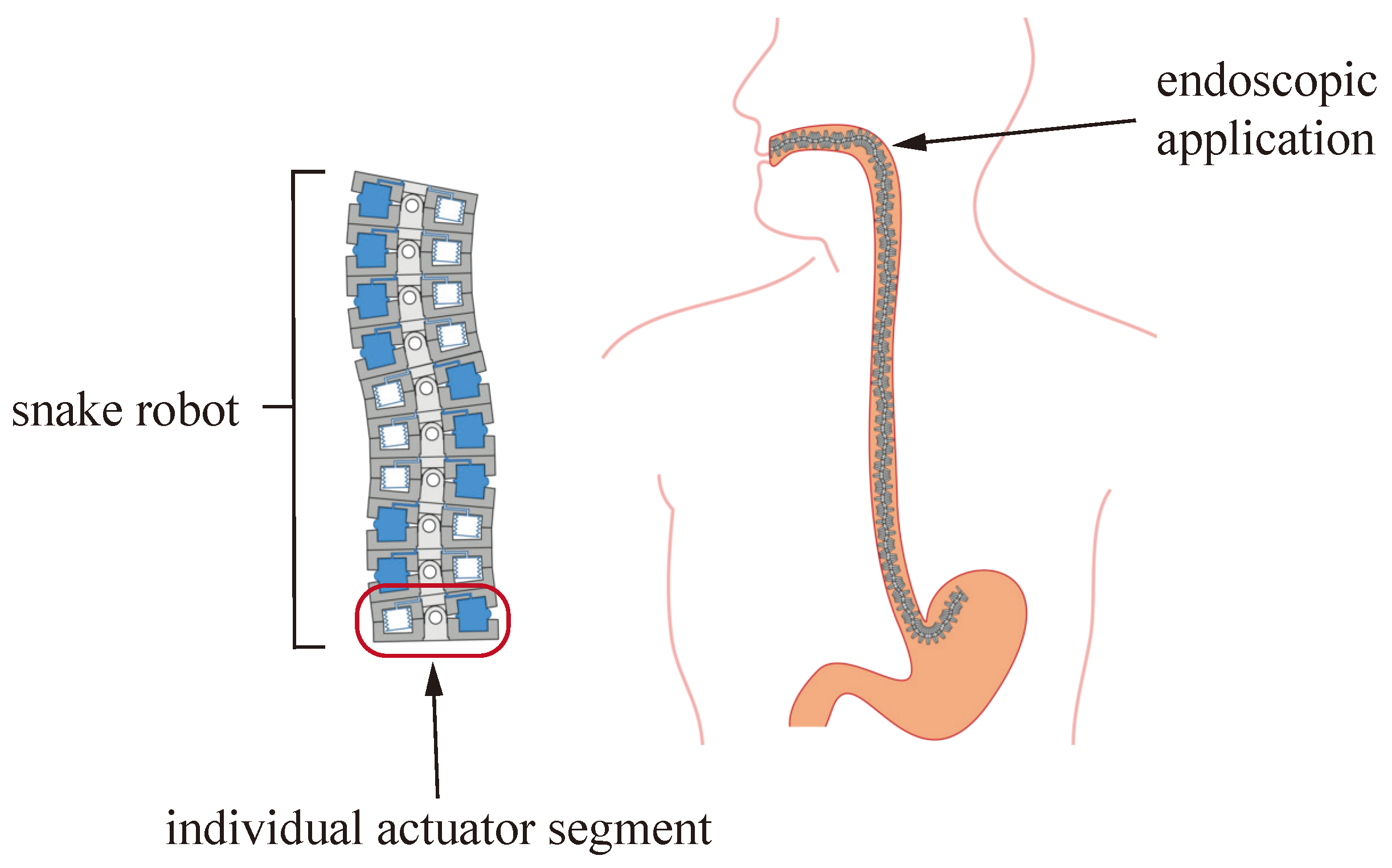
Minimally invasive surgical procedures have revolutionized the field of medicine, enabling faster patient recovery and reduced post-operative complications. Currently, either rigid or flexible endoscopes available on the market are used, depending on the requirements of the procedure. Flexible systems achieve excellent maneuverability; however, due to their flexibility, they struggle to effectively withstand forces during operative procedures. Conversely, rigid endoscopes can provide better stability but significantly limit access possibilities. In this work, we present a novel hydraulic actuator module based on Electrorheological Fluid. This module will serve as the propulsion unit for a snake-like robotic endoscope, ensuring both structural rigidity and flexibility (Figure 1). The development of a modular design with integrated, leak-free valve electronics significantly contributes to the advancement of hydraulically actuated medical robotics.
1.1. Actuation Concept
The actuator is operated using an electrorheological fluid (ERF), which falls into the category of smart fluids. The fluid itself is a suspension containing a carrier liquid (often silicone oil) with electrically polarizable particles (e.g., titanium dioxide) [1]. Within this fluid, the yield stress can be selectively increased reversibly by applying an electrical voltage across two electrodes, generating an electric field. According to [2], the ERF’s flow curve can be described using the Bingham model, with shear stress , yield stress which depends on the electric field strength E, viscosity and shear rate :
The electrorheological effect in a hydraulic channel is depicted in Figure 2. Within milliseconds, dipoles are induced in the solid particles, resulting in an electric torque. Consequently, the particles align along the field lines, forming mechanically loadable chains [2]. The fluid consequently solidifies into a plastic-like substance, retaining this state up to a yield stress of . Beyond , the chains disintegrate, enabling the fluid to flow once again. By switching an electric voltage, this behavior can be intentionally induced, rendering it suitable for use as a valve. The parameters for sizing the valve channel, according to [3], include the volumetric flow rate , the yield stress of the fluid dependent on the electric field E, and the maximum pressure to be switched, i.e., the pressure difference .
with viscosity , valve channel height h, valve channel width b, and valve channel length L. The pressure difference consists of the component attributed to the intrinsic viscosity of the fluid and the pressure difference that can be activated by the electro-rheological effect. In designing the valve channel geometry, attention should be paid to not choosing the valve channel height to be excessively high, particularly in accordance with Equation (2), to minimize the geometric influence.
The use of an electrorheological fluid for hydraulic actuation brings about two significant advantages. Firstly, ERF offers an excellent possibility for miniaturization by eliminating the need for mechanically moving valve components. Secondly, hydraulics provide high power density, ensuring that even in miniaturized actuators, the driving forces remain high [4]. Hydraulic actuators are particularly well-suited for actuating soft robots that allow for safe interaction with humans [5]. At the same time, they can be stiffened, creating an ideal platform for manipulations. Regarding applications in medical robots, hydraulic actuators do not require ferromagnetic components, which is crucial for applications in magnetic resonance imaging (MRI) environments to reduce the risk of artifact generation [6]. Fast response times as well as the easy control of valves via thin high-voltage wires also make the use of ERF appealing. This work presents a novel integrated valve concept for controlling a 3D-printed and miniaturized actuator module for application in endoscopy. Our contributions are:
- Development of a suitable manufacturing process for miniaturized and pressure-tight ERF hydraulics.
- Integration of a suitable sensor for measuring the actuator rotation.
- Establishment of a control system to maneuver the actuator module to a desired position.
1.2. Related Work
Hydraulic actuator constructions often consist of two or more bellows mounted between two platforms. The pressure variation in the individual bellows and an appropriate cascading of the actuator modules enable multi-directional bending and elongation with a variable stiffness of the snake robot. This is demonstrated, among others, in research works by [7,8,9].
In the domain of minimally invasive surgery, well-established actuation techniques for soft snake robot concepts have garnered significant attention. These techniques encompass fluid-driven, cable-driven, and electromagnetic-driven methodologies [10]. Specifically focusing on fluid-driven concepts, the spatial constraints posed by endoscopic actuators often necessitate the external placement of conventional fluid valves. Consequently, the sequential interconnection of actuator segments is frequently confined to a mere two or, at most, three actuators due to the increasing proliferation of input and output connections for each actuator segment [11]. The potential for miniaturization is notably heightened in cable- and wire-driven actuators, wherein slender cables traverse multiple actuator segments. However, this advantage comes at the cost of heightened frictional losses. It is pertinent to note that within this context, the cable-driven mechanism remains positioned externally to the snake robot, demanding a substantially more intricate design and control effort [12]. Electromagnetic drive modules necessitate intricate apparatus to sustain a stable magnetic field for the facilitation of motion control. Additionally, the ability to assume intermediary positions is not feasible, resulting in a curtailed range of motion. Nonetheless, electromagnetic actuators can be miniaturized down to the millimeter scale [10]. The application of ERF in robotic systems is not very widespread. They have primarily been used for the implementation of active dampers and couplings [13,14]. However, there are also works that demonstrate their use in soft robotics [15,16]. The valve presented in [15] even illustrates the possibility of manufacturing ER valves directly through 3D printing. The presented valve design features electrodes that do not come into direct contact with the ERF. However, with this external electrode arrangement, we were unable to manipulate our ERF. Therefore, a design with electrodes in direct contact was pursued. In [17], an alternating pressure source was proposed to manipulate a hydraulic finger through ER valves. This alternating pressure source allows for the use of a single pressure line, further favoring miniaturization.
2. Materials and Methods
2.1. Actuator Design
The application in endoscopy required an exceptionally space-efficient actuator design. The endoscopic application was limited to oral access because, in the initial stages, it was technically easier to implement due to the lower torsion of the endoscope. The esophagus of an adult human has a diameter of approximately 20 mm. Consequently, gastroscopes often have an overall diameter of 5–10 mm [18]. The technical challenges within these size ratios are immense, which was why, in the initial actuator concept, an overall diameter of 20 mm was aimed for. Subsequent developments should build upon this concept to achieve further miniaturization. The developed single actuator configuration is depicted in Figure 3. The bellows were designed using a semi-circular geometry with a maximized surface area to maintain actuator force even at lower hydraulic pressures. The actuator assembly was composed of a sandwich structure consisting of individual 3D-printed modules. These modules served two primary functions: forming the valve body itself and connecting the antagonistic bellows to one another through a pivot joint (Figure 3).
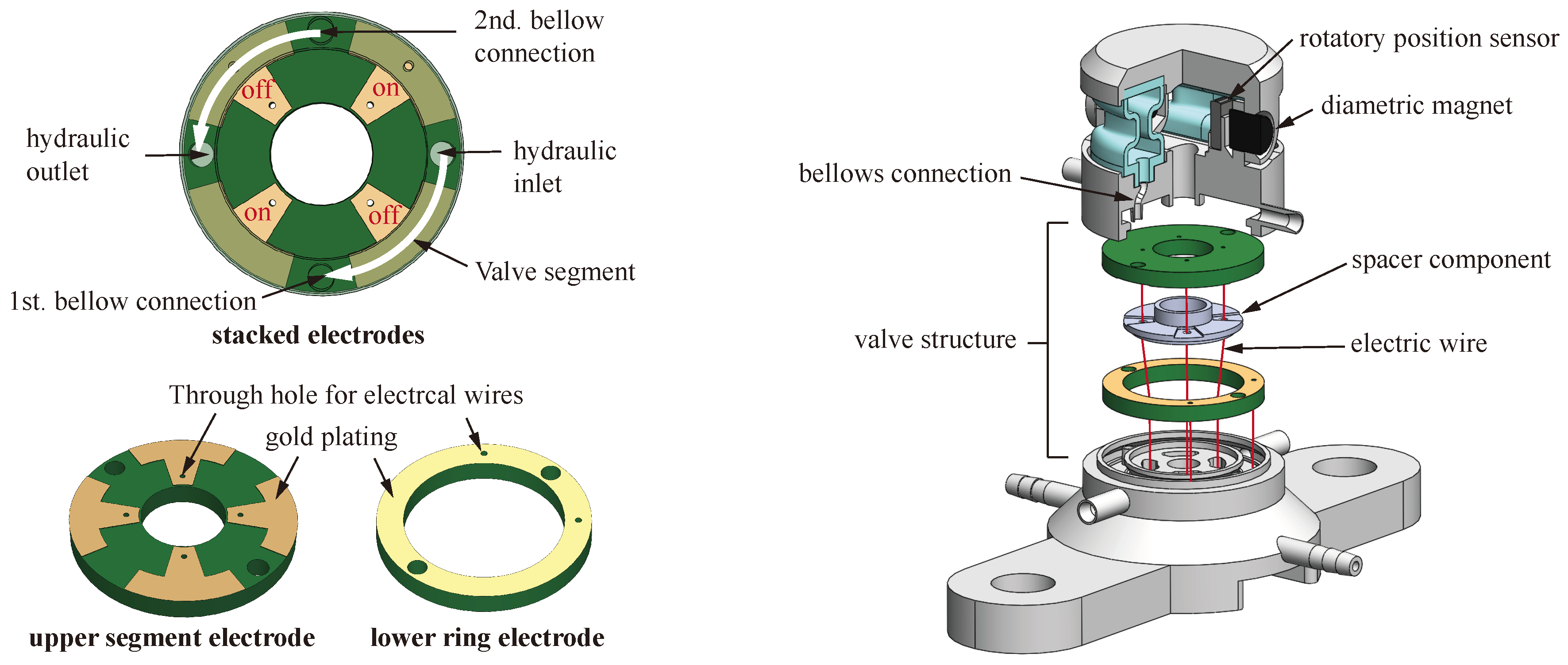
As elucidated in Section 1, an ER valve necessitates the presence of two opposing electrodes to modulate the yield stress of the ERF via the application of an electric field. Collectively, each actuator module required four valves to facilitate the implementation of inlet and outlet channels for the two bellows. Figure 4 illustrates the structure of the microvalve. To achieve space-efficient integration of the four-valve electrodes, two PCBs (Printed Circuit Boards) were designed using the open-source software KiCad. Within the valve body, these two PCBs were spatially stacked on top of each other (Figure 4 right). The upper PCB was divided into four segments at the valve locations. The lower PCB functioned as the counter electrode and was designed as a simple ring. The valve concept becomes evident when examining Figure 4 on the left side and superimposing the two PCBs. In this scenario, two opposing segments of the valve on the upper PCB were connected to the voltage source. The ring electrode served as the electrical ground. This arrangement facilitated the transfer of the ERF from the hydraulic pressure side to the first bellows connection. Simultaneously, the valve segment of the second bellows connection was open, allowing the ERF to flow from the second bellows into the drain, resulting in an actuator tilting motion. To return the actuator to its initial position or to tilt it in the opposite direction, the ring electrode was connected to the voltage source, while the other two opposing valve segments acted as electrical grounds.
To control the actuator for different tilt angle positions and directions, it was necessary to integrate a sensor that can detect and reproduce these movements. The tilt angle range of the sensor is degrees per side, resulting in a total excursion of the actuator of 40 degrees. The contactless rotational angle sensor AS5600 (ams-OSRAM AG, Austria) has been utilized for a precise and easily miniaturizable angular measurement. This sensor measures the absolute angle of a diametrically magnetized permanent magnet rotating on the vertical axis with respect to the sensor. The magnet was directly integrated as a pivot pin into the upper half of the frame, as shown in Figure 4 right. The sensor covers an angle range from 18 to 360 degrees. Through the integrated I2C interface, the sensor’s gain was programmed based on the actuator’s angular deflection, thus enhancing accuracy. For the overall assembly of the snake robot from individual actuator modules, a concept has been developed to facilitate hydraulic pressure supply through a central high-pressure and low-pressure line. However, for the subsequent experiments, initially, only a single actuator module was assembled and tested. The arrangement of the actuator modules is illustrated in Figure 5a. Each actuator module was positioned with a 90-degree offset to achieve the snake-like motion.
The sectional view in Figure 5b illustrates the central hydraulic lines for the high-pressure and low-pressure channels. The connection between the bellows must be made of a flexible material to prevent collisions due to the tilting motion of the upper frame half of the actuator. Due to the limited space, the inner diameter of the individual channel was only 1 mm, with a wall thickness of 0.5 mm. For a simplified assembly of the slender connecting hoses, they were linked together using ring segments at both the top and bottom (see Figure 5c). Specific inserts for the upper and lower ring segments were provided at their respective connection points. This facilitated easy insertion from both the top and bottom during the assembly process.
2.2. Actuator Fabrication
For the fabrication of a miniaturized hydraulic actuator utilizing electrorheological fluid, various manufacturing processes were considered. The foremost challenge within the manufacturing process lies in ensuring a compact and enclosed construction that amalgamates diverse material rigidities. Additionally, the valve electrodes had to be directly inserted into the hydraulic channel. Initial deliberations focused on casting methods utilizing a core of fusible wax; 3D-printed negative molds of the actuator hydraulics were developed for this purpose, facilitating the creation of wax molds. Valve electrodes were then placed onto the wax negative molds. Subsequently, the wax negative molds, along with the electrodes were subjected to silicone dip molding. Ultimately, the liquid wax altered the material properties of the silicone during the debinding process, rendering it prone to cracking and brittleness. Consequently, this manufacturing process did not yield satisfactory outcomes. A conventional manufacturing approach for producing intricate geometries is 3D printing. Table 1 provides an overview of the examined 3D printing techniques, comparing their respective properties. Certain 3D printing technologies, such as Fused Deposition Modeling (FDM) or Multi Material Jetting (MMJ), even enable pause printing at a desired height, allowing for the insertion of components or electrical elements. Nonetheless, FDM methods suffer from the drawback of limited precision, making the production of miniature components more challenging [19]. The layer-by-layer filament extrusion process may induce imperfections, consequently facilitating leaks in hydraulic components.
MMJ printing technologies, on the other hand, are significantly more precise and also enable the production of small-scale components with varying material stiffness. However, the material properties of MMJ-technologies are often brittle and light-sensitive, making flexible materials more prone to leakage [20]. The high costs of these 3D printers, as well as the labor-intensive post-processing associated with this technology, further limit the use of this manufacturing method. Stereolithography (SLA), a 3D printing technology that employs UV laser-assisted layer curing, facilitates the production of highly intricate and small components with a high degree of accuracy. The curing of the layer by UV laser penetrates both the freshly applied layer and the underlying layer, resulting in an excellent bonding between the layers. The subsequent curing under UV light ensures complete polymerization [21]. In contrast to other 3D printing technologies in Table 1, this results in components that demonstrate high hydraulic tightness. The flexible material Elastic 50A (Formlabs, Boston, MA, USA) is capable of withstanding multiple load cycles, further emphasizing the advantages of SLA printing technology [22]. However, a drawback of this manufacturing process is the limitation of printing with only a single material during the printing process. During the printing process, it is not possible to insert and integrate components into the printed parts, as the printed parts are immersed in a bath of 3D printing resin with each layer. As a result, components must subsequently be assembled in a modular fashion. Nonetheless, a modular assembly of the actuator necessitates a pressure-tight connection of individual parts, which is developed and presented herein. Adhesive connections, such as with instant glue or multi-purpose adhesive, do not lead to reliably sealed connections, as the adhesives are often rigid and lose their adhesive strength after a certain period of time. Especially with flexible materials that exhibit low surface energy, adhesive forces can mostly be established through prior surface treatments [23,24]. The developed assembly connection thus consisted of an assembly process using a flexible (SLA) 3D printing material which was injected as a liquid into the components and subsequently cured under UV light. For this purpose, channels were introduced into the 3D printed valve halves and provided with a sprue and a vent (Figure 6). The sprue and vent were easily removed with pliers after the manufacturing process.
Through this manufacturing process, the PCB electrodes were encapsulated into the respective valve half and pressure-tightly connected to the 3D-printed body. Elastic 50A was used as a flexible 3D printing material for bonding and sealing. This material exhibits similar material properties to silicone with the same Shore hardness [22]. The valve halves were made of formlabs Clear, which possesses transparent material properties and is thereby UV transmissive. The connection wires of the electrodes were guided outward through a central channel (Figure 4 right). As a result, the segments of the upper electrode were designed in a T-shape to the interior (Figure 4 left) to allow the wires to pass by the lower ring electrode. In order to define the channel width of the segment electrode, a spacer was constructed (Figure 6). The connection of the spacer was achieved by applying the SLA material Elastic 50A and curing it under UV light. In the next step, the two valve halves were assembled. The contact surfaces were coated once again with Elastic 50A and then the entire valve body was cured under UV light. The connection of the bellows to the upper and lower frame halves followed the same manufacturing process. However, before the bellows assembly, the rotary angle sensor AS5600 (ams-OSRAM AG, Premstätten, Stmk, Autria) was inserted. The sensor cables were also threaded through the channel in the center of the actuator. The joint design and the assembly method at the bellows ensured that the bellows could be relatively easily replaced. This was a significant advantage in the case of a bellows failure.
3. Experiments
Experiment Setup
The actuator was integrated into a test bench, the architecture of which is shown in Figure 7, where the hydraulic inlet was connected to a syringe filled with electrorheological fluid. The fluid consisted of Titanium dioxide nanoparticles and silicone oil (GER STD 0201, Smart Materials Laboratory, Hong Kong, China). Figure 8 depicts the real test stand setup. The dimensions of the actuator are illustrated in Figure 8b,c using a 10-cent coin as reference. The test stand experiments are shown in Figure 8d,e.
The initial experiments demonstrating the behavior of the fluid in a valve circuit were presented in [3], which is why no explicit attention is given to it again here. A constant fluid pressure was achieved by connecting the syringe to pressure-controlled compressed air. The arrangement of the ER-valves as a hydraulic bridge circuit is illustrated in Figure 7 and corresponds to the valve logic from Figure 4. In the block diagram depicted here, the outer electrodes represent the upper segment electrode, and the inner electrodes represent the lower ring electrode. The opposite segments of the upper electrode were connected to the negative and positive poles of a 5 kV high voltage source (Ultravolt 5HVA24-BP1, Advanced Energy Inc., Denver, CO, USA) as shown in Figure 7. To control the voltage of the lower ring electrode, high-voltage optocouplers were used, thus making it possible to switch the voltage of the ring electrode between the high and low levels. In the circuit shown in Figure 7, the ring electrode is set to a positive voltage, causing the ERF to enter the left bellows. Simultaneously, the right bellow is compressed, allowing the ERF to flow from there through the valve into the drain. The optocouplers and position sensors were connected to a data acquisition system to enable control using a computer running Simulink. The duty cycle of a 100 Hz pulse width modulated signal was used to achieve analog control of the valves. For controlling the actuator in Simulink, a PID block was utilized, although it was employed as a PI controller only. The control signal of the PI controller is determined according to the following equation [25]:
Here, represents the proportional value (P), and is the integral value (I). The error signal denotes the difference between a predetermined setpoint and the current output signal. The error signal here was determined by the deviation between the target angle and the actual angle obtained from the rotational sensor, and it was used as the controller input to the Simulink PI block. The controller then calculates an appropriate duty cycle value between 0 and 1. The adjustment of the control parameters was conducted by manually tuning the P and I terms based on the system’s step response. The set values for the proportional term were and for the integral term (refer to Figure 8d).
4. Results
The functioning of the PI control of the actuator was examined using a target angle profile (Figure 8e, orange curve). The actuator deflection was set to 10 degrees in both the positive and negative directions, corresponding to half of the maximum tilt angle of 20 degrees. After reaching the setpoint, it was held for a duration of 35 s to observe the settling behavior. During this time, an overshoot of up to 1 degree was observed for the initial three target angle increments. However, the measurement curve gradually approached the setpoint over time. With a longer simulation duration, the setpoint could potentially be reached. Nevertheless, the possible simulation duration was reduced by the limited number of cycles the 3D-printed bellows were able to withstand. Due to the frequent expansion and compression of the bellows, failure occurred after approximately 10–15 cycles, causing the bellows to rupture. In Figure 8e, the failure of the bellows can be observed, which occurred when the target position was changed from −10 degrees to 0 degrees. Due to the sudden pressure release, the measurement signal significantly exceeds the setpoint of 2.6 degrees (Figure 8e, blue curve). The response time of the actuator primarily depends on the controller parameters, with a significant influence on the pump pressure. Increased pump pressure allows the ER fluid to flow more rapidly through the channels into the bellows, improving the actuator’s ability to track the setpoint. To achieve an appropriate response time for the controller settings and the experimental procedure, an evaluation of the pump pressure had to be conducted, keeping it within the bellows expected lifespan. Consequently, the pump pressure was gradually increased to 2.4 bar. At this pump pressure, response times between 6 and 8 s were measured. The final actuator return to the zero position cannot be considered due to the bellows failure.
The silicone-like photopolymer material Elastic 50A undergoes a rapid aging process. After two to three days following the printing and curing process (Formlabs Form Cure, 60 degrees for 20 min), the material properties became brittle, resulting in a faster material failure. An accelerated aging process was observed when the 3D-printed bellows were exposed to natural UV radiation. Additionally, the 3D printing process itself results in a weakening of the components due to layer-by-layer material deposition, which can be avoided through casting processes. Silicone cast bellows would be expected to provide better long-term stability due to the closed material layer, thereby enabling longer testing periods. This would significantly enhance the characterization of the actuator, as tuning of the controller must be adjusted with each bellows replacement. Simultaneously, higher system pressures are allowed, improving response times during control operations. However, the bonding method developed here shows significant potential. In the experiments, there were no leakages at any of the connection points. It is noteworthy that this manufacturing method reliably realizes very small channels (channel height: 1 mm and channel width: 2.2 mm) while integrating valve electronics.
5. Discussion
This work presents the development of a miniaturized hydraulic tilting actuator as part of a robotic endoscope, based on electrorheological fluid. By utilizing precise SLA 3D printing technology and a developed assembly technique for the components, it was possible to create a hydraulically sealed 3D printed actuator with integrated valves and a sensor. The encapsulation of the electrodes with the 3D printing material Elastic 50A proved to be the most effective solution. Component irregularities and tolerances, which significantly contributed to system leakage, were easily compensated for. The advancements in this development constitute a significant contribution to the implementation of hydraulically sealed actuation systems in medical robotics. Due to the sterility requirements in medicine, any leakage is not tolerated [26]. The use of electrorheological fluid allows for the development of highly miniaturized valves to be integrated into the robotic system. Simultaneously, the nearly incompressible properties of hydraulic actuation provide a high power density, which is essential for effective miniaturization [27]. Additional development work would be needed for endoscopic application to achieve a maximum outer diameter of up to 10 mm.
The functionality of the tilting actuator was demonstrated through PI control in bench tests with an accuracy of 0.6 to 1 degree and response times between 6 and 8 s. The proposed electrorheological valve system consisting of four valves that are controlled using a single high-voltage PWM signal proved suitable for the control of the two antagonistic actuators. However, functional tests also revealed weaknesses in the 3D printed bellows. Extensive testing including system identification and controller tuning was not possible using the current test setup. Future work must, therefore, focus on more stable and durable hydraulic bellows that can withstand higher pressure and more movement cycles. The production of bellows through silicone casting would likely result in increased durability under changing loads. However, it has been shown that the assembly technique presented here cannot be applied with silicone, as the photopolymer does not form a bond with the silicone. Alternative attempts using silicone adhesive (SIL-POXY™/1, Smooth-On Inc., Macungie, PA, USA) have also failed to achieve a satisfactory bond between an SLA 3D printing material and silicone. A challenge in the context of silicone casting is the development of a suitable casting method, preserving the material properties of the silicone while retaining a small-scale component geometry. At that time, the available materials and joining methods were unable to provide a durable solution. After the experiments, the material Silicone 40A (Formlabs, Boston, MA, USA) was introduced, presenting a new perspective for achieving long-term stable 3D-printed bellows. The material is composed entirely of silicone, allowing for the effective combination of silicone’s optimal properties with the versatility of 3D printing. The initial experiments revealed that the joining method presented here, using the 3D printing material, did not achieve sufficient adhesion. Subsequent experiments, therefore, initially focused on introducing a more suitable joining method. Upon successful connection of the elastic bellows with the actuator frame, it is expected that the bellows will exhibit higher pressure tolerance, thereby allowing for an improved actuator response time. Subsequent studies will be conducted using this material to investigate its long-term stability. Consequently, the long-term stability of the bellows enables longer experiments without material failure and enables more precise position control.
From this work, future research approaches include:
- Further miniaturization development to achieve a maximum outer diameter of 10 mm
- Development of integrable and long-term stable bellows
- Serial connection of multiple actuators to form a snake-like robot
- Control of the assembled snake robot.
Author Contributions
Conceptualization, F.S. and M.S.; methodology, F.S.; investigation, F.S. and J.H.; software, F.S. and M.S.; validation, F.S., J.H. and M.S.; writing—original draft preparation, F.S.; writing—review and editing, F.S. and M.S.; visualization, F.S.; supervision, J.S.; project administration, M.S.; funding acquisition, J.S. All authors have read and agreed to the published version of the manuscript.
Funding
This research was funded by German Research Foundation (Deutsche Forschungsgemeinschaft DFG) under the grant number 433586601.
Data Availability Statement
No new data were created or analyzed in this study. Data sharing is not applicable to this article.
Conflicts of Interest
The authors declare no conflicts of interest.
References
- Fatikow, S. Mikroroboter und Mikromontage: Aufbau, Steuerung und Planung von Flexiblen Mikroroboterbasierten Montagestationen, softcover reprint of the hardcover 1st edition 2000 ed.; B.G. Teubner: Stuttgart/Leipzig, Germany, 2000. [Google Scholar]
- Janocha, H. Unkonventionelle Aktoren; Oldenbourg Verlag: Oldenbourg, Germany, 2010. [Google Scholar] [CrossRef]
- Siegfarth, M. Hydraulic miniature actuators controlled by electrorheological fluid. In Proceedings of the ACTUATOR 2018—16th International Conference and Exhibition on New Actuators and Drive Systems, Conference Proceedings, Bremen, Germany, 25–27 June 2018. [Google Scholar]
- Liljebäck, P. Snake Robots: Modelling, Mechatronics, and Control, 1st ed.; Advances in Industrial Control Ser; Springer London Limited: London, UK, 2013. [Google Scholar]
- Lee, C.; Kim, M.; Kim, Y.J.; Hong, N.; Ryu, S.; Kim, H.J.; Kim, S. Soft robot review. Int. J. Control. Autom. Syst. 2017, 15, 3–15. [Google Scholar] [CrossRef]
- Elhawary, H.; Zivanovic, A.; Davies, B.; Lampérth, M. A review of magnetic resonance imaging compatible manipulators in surgery. Proc. Inst. Mech. Engineers. Part H J. Eng. Med. 2006, 220, 413–424. [Google Scholar] [CrossRef] [PubMed]
- Bailly, Y.; Amirat, Y.; Fried, G. Modeling and Control of a Continuum Style Microrobot for Endovascular Surgery. IEEE Trans. Robot. 2011, 27, 1024–1030. [Google Scholar] [CrossRef]
- Suzumori, K.; Endo, S.; Kanda, T.; Kato, N.; Suzuki, H. A Bending Pneumatic Rubber Actuator Realizing Soft-bodied Manta Swimming Robot. In Proceedings of the Proceedings 2007 IEEE International Conference on Robotics and Automation, Rome, Italy, 10–14 April 2007; IEEE: Toulouse, France, 2007; pp. 4975–4980. [Google Scholar] [CrossRef]
- Ranzani, T.; Gerboni, G.; Cianchetti, M.; Menciassi, A. A bioinspired soft manipulator for minimally invasive surgery. Bioinspiration Biomim. 2015, 10, 035008. [Google Scholar] [CrossRef] [PubMed]
- Chen, X.; Zhang, X.; Huang, Y.; Cao, L.; Liu, J. A review of soft manipulator research, applications, and opportunities. J. Field Robot. 2022, 39, 281–311. [Google Scholar] [CrossRef]
- Ranzani, T.; Cianchetti, M.; Gerboni, G.; de Falco, I.; Menciassi, A. A Soft Modular Manipulator for Minimally Invasive Surgery: Design and Characterization of a Single Module. IEEE Trans. Robot. 2016, 32, 187–200. [Google Scholar] [CrossRef]
- Amanov, E.; Nguyen, T.D.; Burgner-Kahrs, J. Tendon-driven continuum robots with extensible sections—A model-based evaluation of path-following motions. Int. J. Robot. Res. 2021, 40, 7–23. [Google Scholar] [CrossRef]
- Davidson, J.R.; Krebs, H.I. An Electrorheological Fluid Actuator for Rehabilitation Robotics. IEEE/ASME Trans. Mechatron. 2018, 23, 2156–2167. [Google Scholar] [CrossRef]
- Furusho, J.; Zhang, G.; Sakaguchi, M. Vibration Suppression Control of Robot Arms Using a Homogeneous-Type Electrorheological Fluid. In Proceedings of the International Conference on Robotics and Automation, Albuquerque, NM, USA, 25 April 1997; IEEE: Toulouse, France, 2000. [Google Scholar]
- Zatopa, A.; Walker, S.; Menguc, Y. Fully Soft 3D-Printed Electroactive Fluidic Valve for Soft Hydraulic Robots. Soft Robot. 2018, 5, 258–271. [Google Scholar] [CrossRef] [PubMed]
- Virta, A.; Timonen, J.V.; Ras, R.H.; Zhou, Q. Force sensing using artificial magnetic cilia. In Proceedings of the IEEE/RSJ International Conference on Intelligent Robots and Systems (IROS), Vilamoura, Algarve, Portugal, 7–12 October 2012; IEEE: Piscataway, NJ, USA, 2012. [Google Scholar]
- Miyoshi, T.; Yoshida, K.; in Eom, S.; Yokota, S. Proposal of a multiple ER microactuator system using an alternating pressure source. Sensors Actuators A Phys. 2015, 222, 167–175. [Google Scholar] [CrossRef]
- Helios Klinikum Aue. Ablauf Einer Magenspiegelung—Gastroskopie. Available online: https://www.helios-gesundheit.de/kliniken/aue/unser-angebot/unsere-fachbereiche/gastroenterologie-hepatologie/patientenwissen-ablauf-gastroskopie/ (accessed on 14 August 2023).
- HUBS. Auswahl des Richtigen 3D-Druckverfahrens: Entscheidungshilfen und Allgemeine Richtlinien, die Sie bei der Auswahl des Richtigen 3D-Druckverfahrens für Ihre Anwendung Unterstützen. Available online: https://www.hubs.com/de/wissensbasis/auswahl-3d-druckverfahren/ (accessed on 5 September 2023).
- Formlabs. Wie Sie den Richtigen 3D-Industriedrucker Auswählen. Available online: https://formlabs.com/de/blog/industrielle-3d-drucker/ (accessed on 5 September 2023).
- Lachmayer, R. Additive Manufacturing Quantifiziert; Springer: Berlin/Heidelberg, Germany, 2017. [Google Scholar]
- Fomlabs. Elastic Resin: Ein Widerstandsfähiges, Weiches und Flexibles 3D-Druckmaterial. Available online: https://formlabs.com/de/blog/elastic-resin-silikon-3d-druck/ (accessed on 15 October 2023).
- KG Rubberpoint. Roh- & Zusatzstoffe. Available online: https://www.kgk-rubberpoint.de/roh-zusatzstoffe/oberflaechenaktivierung-reicht-aus-281.html (accessed on 6 September 2023).
- 3M. Klebstoff- und Klebebandlösungen: Oberflächenenergie Kategorisieren. Available online: https://www.3mdeutschland.de/3M/de_DE/kleben-und-verbinden/schulung-weiterbildung/die-wissenschaft-des-klebens/oberflaechenenergie-kategorisieren/ (accessed on 6 September 2023).
- University of Michigan. Control Tutorials for Matlab & Simulink. Available online: https://ctms.engin.umich.edu/CTMS/index.php?example=Introduction§ion=ControlPID (accessed on 13 March 2024).
- Su, H.; Kwok, K.W.; Cleary, K.; Iordachita, I.; Cavusoglu, M.C.; Desai, J.P.; Fischer, G.S. State of the Art and Future Opportunities in MRI-Guided Robot-Assisted Surgery and Interventions. Proc. IEEE. Inst. Electr. Electron. Eng. 2022, 110, 968–992. [Google Scholar] [CrossRef] [PubMed]
- Frishman, S.; Kight, A.; Pirozzi, I.; Coffey, M.C.; Daniel, B.L.; Cutkosky, M.R. Enabling In-Bore MRI-Guided Biopsies With Force Feedback. IEEE Trans. Haptics 2020, 13, 159–166. [Google Scholar] [CrossRef] [PubMed]
Figure 1.
Schematic representation of the hydraulic snake-like robot for endoscopic application.

Figure 2.
Use of the ER effect for a hydraulic valve. On the left, with high voltage applied. ERF particles align along the electric field lines and from mechanically stable chains. On the right, without high voltage. The ERF particles flow through the channel.
Figure 2.
Use of the ER effect for a hydraulic valve. On the left, with high voltage applied. ERF particles align along the electric field lines and from mechanically stable chains. On the right, without high voltage. The ERF particles flow through the channel.

Figure 3.
ER actuator CAD design: On the left, there is a side view with dimensions for the actuator’s width and height, as well as a sprue and venting for the valve manufacturing process. On the right, 3D representation of the actuator module.
Figure 3.
ER actuator CAD design: On the left, there is a side view with dimensions for the actuator’s width and height, as well as a sprue and venting for the valve manufacturing process. On the right, 3D representation of the actuator module.

Figure 4.
ER valve structure. On the left, PCB design of the lower ring electrode and upper segment electrode. Stacked electrode view, demonstrating the valve logic using a circuit example. On the right, exploded view of the ER valve assembly.
Figure 4.
ER valve structure. On the left, PCB design of the lower ring electrode and upper segment electrode. Stacked electrode view, demonstrating the valve logic using a circuit example. On the right, exploded view of the ER valve assembly.

Figure 5.
Construction of the snake-like robot with a central hydraulic connection to the individual actuator modules. (a) snake-like robot constriction (b) Sectional view of an actuator module with a central pressure line and a connector to the next actuator module. The upper frame simultaneously represents the lower valve half of the next actuator. (c) Hydraulic connector with two channels for high-pressure and low-pressure connections.

Figure 6.
3D-printed valve halves with channels for casting the electrodes. On the top, the upper valve half with the segment electrode. On the bottom, the lower valve half with the ring electrode.
Figure 6.
3D-printed valve halves with channels for casting the electrodes. On the top, the upper valve half with the segment electrode. On the bottom, the lower valve half with the ring electrode.

Figure 7.
Block diagram of the test bench setup of the ERF actuator, including hydraulic and electrical schematics.
Figure 7.
Block diagram of the test bench setup of the ERF actuator, including hydraulic and electrical schematics.

Figure 8.
Experimental setup for actuator functional test. (a) A syringe filled with ERF was connected to both the pneumatic pressure side and the hydraulic connection of the actuator. On the other hydraulic connection of the actuator, an empty syringe was connected. The HV cables and sensor cables were connected to the high-voltage source, HV optocouplers, and to the I/O of the data acquisition box. (b) Bottom view of the actuator with sensor and high-voltage wire routing through the center of the actuator. (c) Perspective view of the actuator with representation of scale using a 10 cent coin. (d) Tilting motion and the neutral position of the actuator, in dependence on the PI control curve, along with the testing parameters for the experimental procedure. (e) PI controller diagram plotted with degrees over time. The setpoint curve is shown in orange, featuring a 10-degree tilt of the actuator in the positive direction, a neutral position, and a 10-degree tilt in the negative direction. Dwell times per position step were 35 s. The blue curve represents the controlled actuator trajectory. Rupture of one bellow occurred at 105 s.


Table 1.
Comparison of Investigated Printing Technologies.
| Attributes | FDM | MMJ | SLA |
|---|---|---|---|
| Printing process | Filament Extrusion | Material Droplets | Photopolymerization |
| Tolerances | ±0.5% | ±0.1–±0.2% | ±0.1–±0.2% |
| Material layering | applying | applying and curing | applying and layer penetrating laser curing |
| Post-processing process | Low | High | Medium |
| Stop printing (to insert parts) | Yes | Yes | No |
| Costs | Low | High | Medium |
Disclaimer/Publisher’s Note: The statements, opinions and data contained in all publications are solely those of the individual author(s) and contributor(s) and not of MDPI and/or the editor(s). MDPI and/or the editor(s) disclaim responsibility for any injury to people or property resulting from any ideas, methods, instructions or products referred to in the content. |
© 2024 by the authors. Licensee MDPI, Basel, Switzerland. This article is an open access article distributed under the terms and conditions of the Creative Commons Attribution (CC BY) license (https://creativecommons.org/licenses/by/4.0/).
Share and Cite
MDPI and ACS Style
Sadi, F.; Holthausen, J.; Stallkamp, J.; Siegfarth, M. Development of Novel Hydraulic 3D Printed Actuator Using Electrorheological Fluid for Robotic Endoscopy. Actuators 2024, 13, 119. https://0-doi-org.brum.beds.ac.uk/10.3390/act13040119
AMA Style
Sadi F, Holthausen J, Stallkamp J, Siegfarth M. Development of Novel Hydraulic 3D Printed Actuator Using Electrorheological Fluid for Robotic Endoscopy. Actuators. 2024; 13(4):119. https://0-doi-org.brum.beds.ac.uk/10.3390/act13040119
Chicago/Turabian StyleSadi, Fabian, Jan Holthausen, Jan Stallkamp, and Marius Siegfarth. 2024. "Development of Novel Hydraulic 3D Printed Actuator Using Electrorheological Fluid for Robotic Endoscopy" Actuators 13, no. 4: 119. https://0-doi-org.brum.beds.ac.uk/10.3390/act13040119
Note that from the first issue of 2016, this journal uses article numbers instead of page numbers. See further details here.