Conductive Fabric Heaters for Heat-Activated Soft Actuators


Department of Mechanical Engineering, Columbia University, New York, NY 10027, USA
*
Author to whom correspondence should be addressed.
Actuators 2019, 8(1), 9; https://0-doi-org.brum.beds.ac.uk/10.3390/act8010009
Submission received: 28 December 2018
/
Revised: 11 January 2019
/
Accepted: 18 January 2019
/
Published: 21 January 2019
(This article belongs to the Special Issue New Materials and Designs for Soft Actuators)
Abstract
:We examine electrically conductive fabrics as conductive heaters for heat-activated soft actuators. We have explored various fabric designs optimized for material properties, heat distribution and actuation/de-actuation characteristics of the soft actuators. We implemented this approach in the silicone/ethanol composite actuators, in which ethanol undergoes a thermally-induced phase change, leading to high actuation stress and strain. Various types of conductive fabrics were tested, and we developed a stretchable kirigami-based fabric design. We demonstrate a fabric heater that is capable of cyclic heating of the actuator to the required 80 °C. The fabric with the special kirigami design can withstand temperatures of up to 195 °C, can consume up to 30 W of power, and allows the actuator to reach >30% linear strain. This technology may be used in various systems involving thermally-induced actuation.
1. Introduction
Precise and flexible actuation is currently of interest in the fields of hybrid (soft and rigid) robotics [1], assistive living devices [2], and medical applications through the use of soft robotic actuators [3]. Assimilation of soft components into pre-existing robotic operating systems, such as a pick and place arm, creates hybrid robotic platforms that can perform complex grasping manipulation tasks with acceptable levels of precision [1]. To assist patients overcoming spinal cord injury with activities of daily living, soft robotic gloves with pneumatic elastomer actuators have been implemented, improving hand functionality by 33.42 ± 15.43% based on participant scores of object manipulation tests [2]. In the medical field, soft tethered pneumatic artificial muscle sleeves have been designed to provide an assistive mechanical cardiac function for patients with heart failure [3].
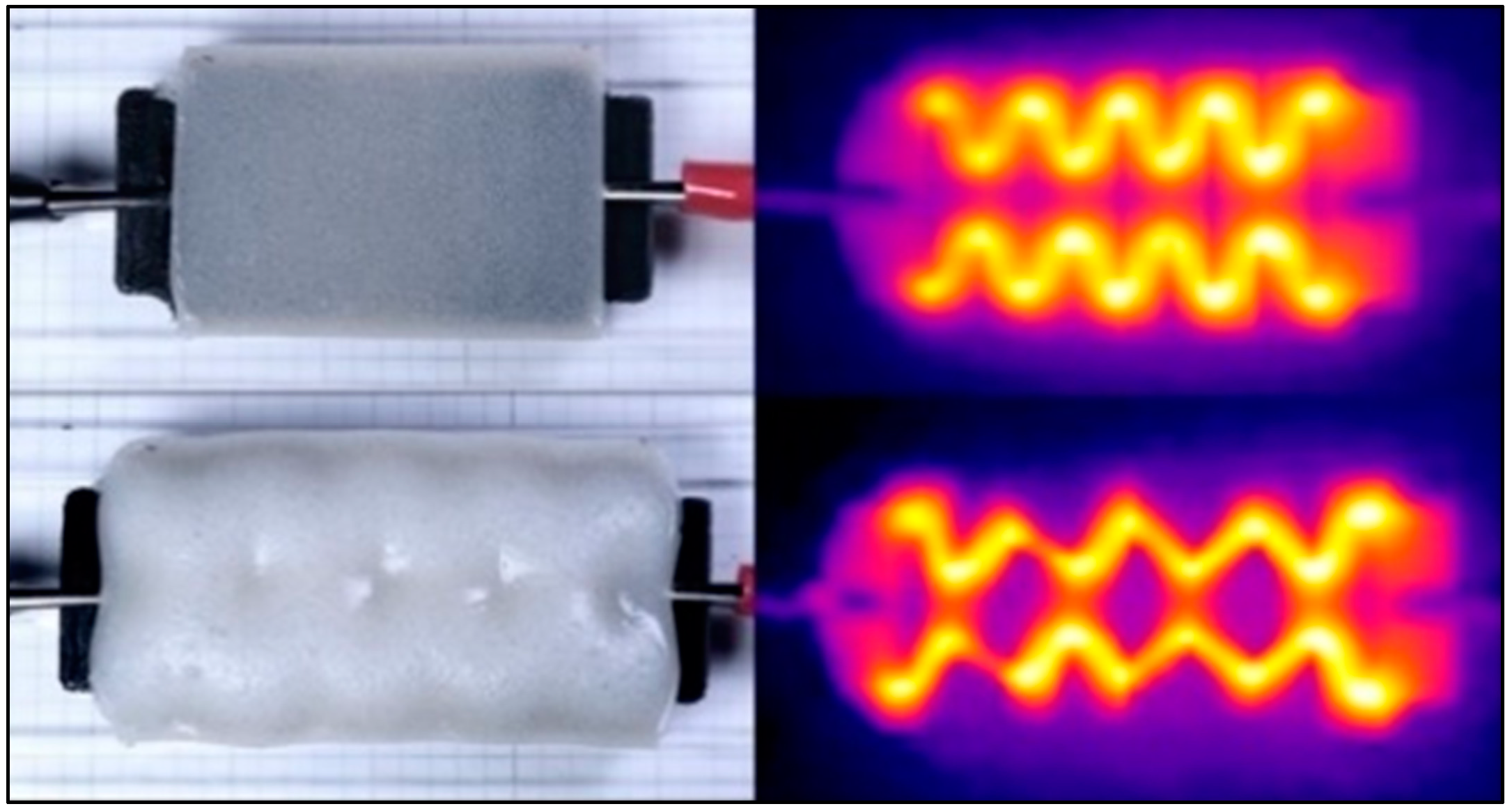
Soft actuators can be classified by their method of actuation. Electroactive gels and dielectric actuators use electrodes to electrically stimulate a polymer or soft dielectric material [4]. Pneumatic actuators and fluid actuators use air and water respectively to inflate a soft mesh bladder for bending or expansion purposes [4]. Thermal actuators are soft actuators that create actuation from thermal expansion and phase change volumetric expansion. This article focuses on the viability of using conductive fabrics as heating elements in thermal actuators, as shown in Figure 1.
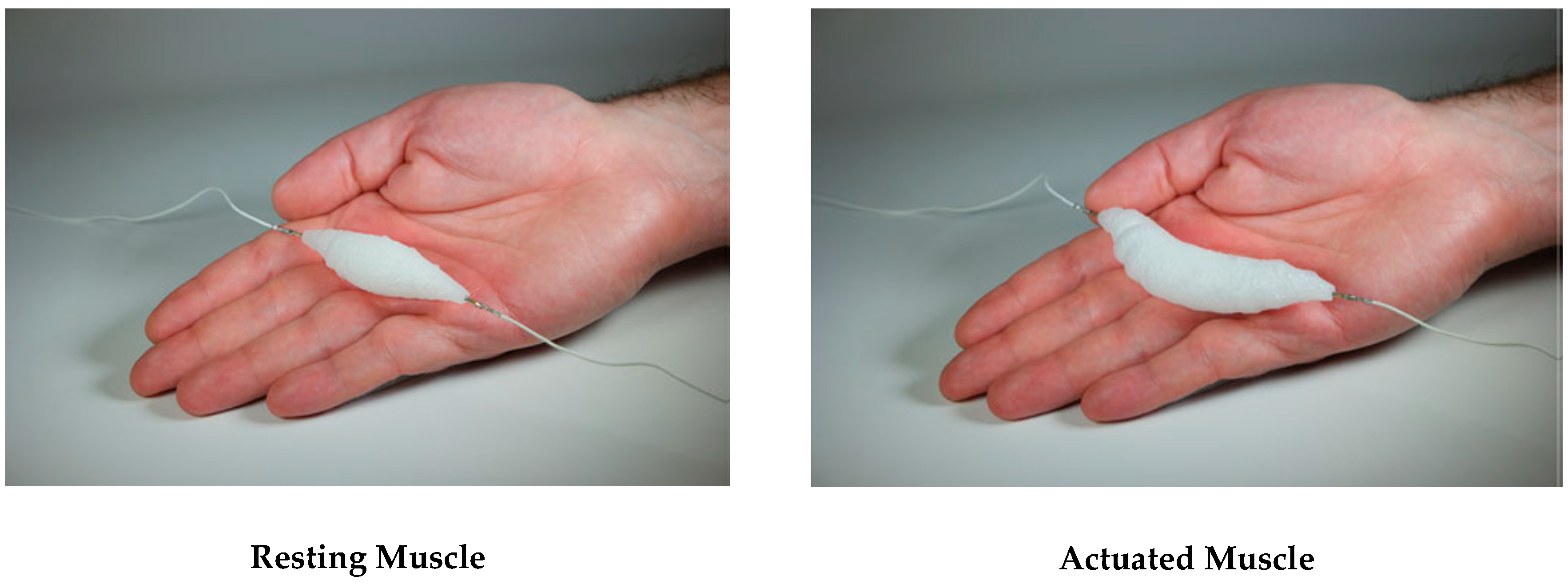
Silicone-ethanol actuators are a type of thermal actuator that expands from the internal pressure of heated vapors. Due to the nature of actuation, silicone-ethanol actuators can be self-contained actuators that do not require bulky external systems, as seen in Figure 2 [5]. These thermally sensitive soft actuators were found to allow permissible strains of up to 900% while using readily available and low-cost materials [5]. These artificial actuators are made of ethanol embedded (20% vol) in a silicone elastomer matrix. Upon heating, the micro-bubbles of liquid ethanol undergo a phase change to ethanol vapor, causing volumetric expansion [6]. Heating can be provided by external sources, such as boiling water or a heat gun, or internally by Joule heaters [7]. These artificial actuators have been used to make soft bi-morph walking robots, McKibben-type muscles, and soft grippers [8].
These thermal actuators have been reportedly activated using a coiled Nichrome 80 (Ni-Cr) resistance wire as a heating element [5], limiting the potential for single-step fabrication. The resistive Ni-Cr wire is effective, but does not provide an even distribution of heat, causing the actuator to expand non-uniformly with time, slowing down the actuation time. Additionally, the coiled heating element is not easily manufacturable, requiring precise hand winding of the wire into a coil and placing it into the actuator material while it is being cast in its mold. An ideal heater for these actuators would be capable of even heating, easily manufacturable to any customizable size, and flex and stretch with the actuator’s expansion and contraction.
Research was conducted to replace the Ni-Cr wire with a conductive intercalated graphite (EIG) silicone composite, to create a fully soft actuator. This silicone heater was made of the same material as the actuator but was combined with expandable pre-prepared dry graphite (Sigma-Aldrich, St. Louis, MO, USA) to create 25–65 Ω soft heaters. The soft heater samples were able to match and outperform the Ni-Cr heater samples in force exertion, achieving up to 200 N and 300 N of blocked force. The disadvantages of these soft heaters are that they require a bulk configuration of the EIG-silicone, they were difficult to connect to the electrical leads of the power supply, and would lose connection between the electrodes after overheating at the ends [8].
Other flexible conductive materials used in soft electronics were examined to replace the current Ni-Cr coil solution. Low melting point alloys, such as gallium-indium alloy, are commonly used in soft electronics applications, due to their low stiffness and capability of withstanding high deformations. This liquid minimally affects the mechanical strain of the soft material it is applied to, making it ideal as a strain gauge or pressure sensor, in which the resistance of a liquid metal channel is dependent on how much the sensor is stretched. These liquid channels and silver epoxy have been used to make conductive traces for circuits [9,10,11,12,13], as well as soft capacitors [9,10]. Liquid metal has been used in “variable stiffness fibers”, in which external heating of these metals would allow the fiber to become >700 times more compliant when the metal is heated past its melting temperature. The phase change allows the material to actuate between a rigid and soft state. In this case, the liquid metal was the actuator material, resistively heated by a conductive copper wire [11].
While not as flexible as low melting point alloys, shape memory alloys (SMA) have been used as a combination actuator and Joule heater. Running current directly through a coiled SMA wire made of nickel, titanium, and copper causes the coil to expand and contract, retaining the coil’s original shape after deformation. Similar to other wire coil heating solutions, the wire can touch itself, creating shorts that cause localized heat concentrations, creating uneven heating [9].
Taking a chemical approach, poly(3,4-ethylenedioxythiophene): Polystyrene sulfonate (PEDOT:PSS) has been used in soft actuators as a thin conductive film Joule heater, reaching up to ~200 °C. With the soft PEDOT:PSS film heater, fully compliant actuators could be fabricated by spin coating, inkjet printing or knife-edge coating the film onto existing soft material, whether it is an elastomer like poly(dimethylsiloxane) (PDMS) or a textile like nylon [14,15,16,17]. Usually up to six layers of PEDOT:PSS are applied, as any additional layers would make the film too rigid and inflexible and would also lower the electrical resistivity of this type of resistive heater [16].
Liquid crystalline elastomers (LCE) are a promising alternative to silicone-ethanol actuators, as they elongate and contract around 80 °C, can be doped with carbon black to improve thermal conductivity, and can displace loads >2500 times heavier than their own weight [18,19]. However, the LCE needs to be heated by an external source to actuate, such as a Kapton film heater, which is made of Cr/Au layers chemically etched onto the coated film [18]. Chemical etching can be a time-consuming, multistep process, and the chemicals involved can be hazardous and dangerous for the environment.
Looking to conductive fabrics as resistive heaters, conductive nylon 6, 6 sewing threads have been twisted into coils to create a “super-coiled” polymer (SCP) muscle that can actuate by contracting when heated [20]. These threaded coils are heat treated while under stress to temperatures over 150 °C, causing the resting length to plastically elongate. These SCP muscles were able to contract up to 10% in length, and to start creating controlled forces in under 30 ms once current was applied through these conductive coils [20]. Paper, a non-stretchable material, has been manipulated using kirigami cutting techniques to improve stretchability [21]. Kirigami designs are instrumental in creating stretchable heaters in this study. In [22], conductive textiles have been implemented as the electrode material for dielectric elastomer actuators (DEA) and electroadhesion actuators (EA), rather than as a heating element. A 2.5 g robot crawler made of one DEA and two EA actuators was shown to move 18 mm in 3 min, achieving a stepping cycle of 0.125 Hz.
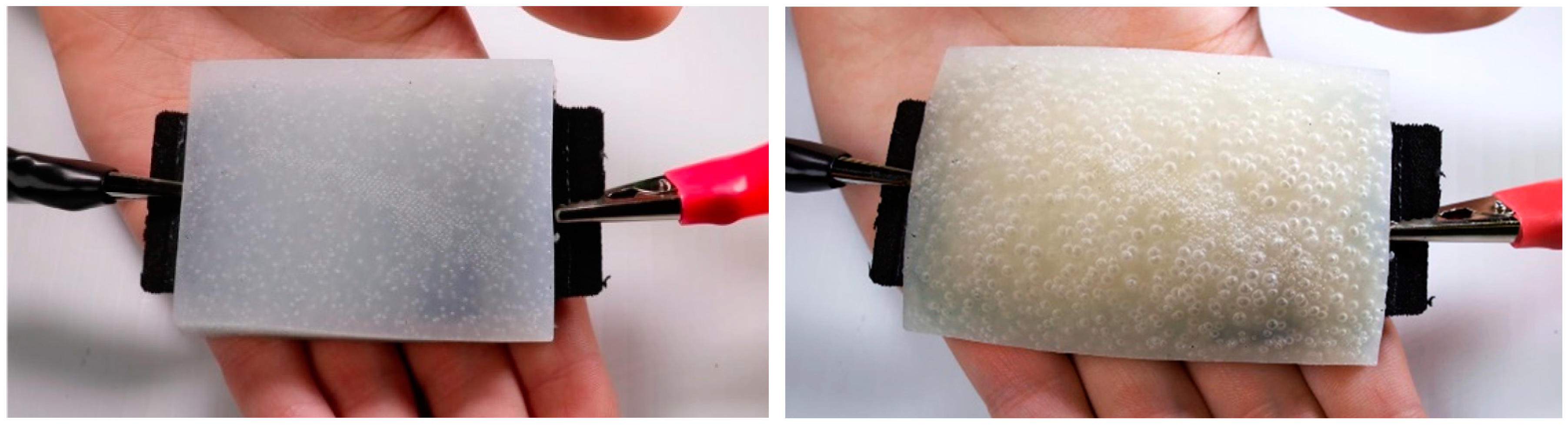
Other than non-conductive fabrics coated with films of PEDOT:PSS, to our knowledge no research has used fabric as a flexible and stretchable heating element. Here we investigate the use of conductive fabrics as a resistive Joule heater, specifically for use in thermally-induced phase change actuators. Each fabric heating pattern was designed to allow for even heating throughout the actuator and to optimize the electrical resistance to match the requirements of that particular soft actuator. Additionally, these fabrics were laser cut in specialized patterns to maximize mechanical compliance, enabling these heating elements to stretch with the actuator as it actuates. These fabric resistive heaters were then cast in soft actuators and have been proven to distribute heat efficiently, allowing for up to 20% to 30% strain during actuation, with fast heating times of around 2 to 4 min to reach 80 °C to 90 °C (Figure 3).
2. Materials and Methods
The silicone-ethanol thermal actuators in this study were composed of ethanol ≥99.5% (Sigma-Aldrich) embedded in a silicone elastomer matrix. This two-part silicone is a non-hazardous and environmentally friendly PDMS-based silicone elastomer, Ecoflex 00-35 (Smooth-On, Macungie, PA, USA), which is widely used in the field of soft robotics for its ease of manufacturing and safe handling. Ethanol was chosen for its low boiling point of 78.4 °C and common use. When mixed into the elastomer, the ethanol (20% by volume) is enclosed and retained in micro-bubbles within the cured silicone. Actuating the assembled actuator requires a heat source to heat the actuator to 80 °C, inducing a phase change in the ethanol from a liquid to a vapor, significantly increasing the volume of the actuator. At 90 °C, the optimal temperature for actuation, the actuator was able to expand to 915% of its original volume [5].
For the silicone/ethanol composite material preparation, ethanol is thoroughly hand-mixed into the 2-part silicone rubber matrix for 60 s. This will evenly distribute the ethanol and create micro-bubbles within the silicone upon curing. Subsequently, the material is poured into a 3D-printed PLA (polyactic acid) mold (printed on an Ultimaker 3 Extended and a Prusa i3 MK3 using Cura and Slic3r PE software respectively) to create a custom-shaped actuator. Each mold was designed to hold the designated fabric heater in place using wall slots sized to that particular heater, aligning it in the center of the actuator. When the mold is filled halfway, the Joule heater is placed on top of the uncured silicone-ethanol and further centered with tweezers. Once the Joule heater is in place, the rest of the silicone-ethanol mixture can be poured in to fill the rest of the mold and is left to cure for 5 min. When the silicone is cured, the actuator is removed from the mold.
To create the currently used wire coil heater, 30-gauge AWG Nichrome 80 wire (80% nickel, 19.5% chromium, 1.45% silicon) is cut to length with wire cutters to the desired electrical resistance (20 Ω), which is measured by a Siglent SDM 3055 digital multimeter. The wire is then anchored against a 3.785 mm diameter screwdriver shaft in the jaws of a DeWalt 20V MAX cordless drill. When the drill runs, the wire is coiled around the screwdriver. At the same time, the operator feeds the wire down the shaft, taking care to keep the winds as evenly spaced as possible. Once the wire is completely coiled, the screwdriver is taken out of the drill and the wire is slid off the end of a screwdriver. The coil is then bent with pliers, making two coils of equal length to ensure that the coil can fit in smaller actuators and to increase the thermal footprint of the heater. Assistive bending tools, printed on a Stratasys J750 PolyJet 3D printer using GrabCAD Print software, were created to align the two coils in parallel, flatten the bend in the wire, and even out the windings. With these printed tools, manufacturing one of these heaters now takes between 5 to 7 min compared to the original time of 25 to 30 min without the tools.
When selecting materials for soft flexible heaters, both conductive fabrics and metal foils were placed under consideration, due to the ease of manufacturing and inherent thin material flexibility. The investigated materials are listed in Table 1.
These fabrics and foils were cut into heating element patterns using handheld scissors, as well as on the Thunder Laser Nova 35 and Full Spectrum P-Series Professional CO2 24 × 16 laser cutter. These laser cutters were used for the fabrics only, as the reflective foils could have damaged the laser cutter’s optics. The patterns were designed in SolidWorks 2016 and cleaned up in AutoCAD, after which they were exported to DXF files to be cut in the laser cutting software RDWorksV8 and RetinaEngrave.
Electrical resistivity tests were conducted using a Siglent SDM 3055 digital multimeter and a Fluke 117 True RMS multimeter when iterating on different heating element patterns to try to attain a resistance of between 10 Ω and 30 Ω. When using the Siglent multimeter and the Fluke multimeter, the recorded resistance was taken after 15 s, once the fluctuations became insignificant. The Siglent multimeter was capable of measuring 150 readings/second and the Fluke multimeter was capable of measuring 32 readings/second. In calculating material resistivity, the Siglent SDM 3055 and Fluke 117 True RMS digital multimeter were used to measure the 2-point resistance of strips of each material at 50 mm, 100 mm, and 150 mm length, taking contact resistance into consideration (see Section 3.2.2). Additional resistance measurements revealed that there was no significant difference in the measured resistance using the 2-point method compared to the 4-point method. For each type of material, a total of 36 samples were measured. These fabric strip samples were cut delicately to avoid unintentional bending, folding or twisting. These materials cut well, maintaining their structural integrity after cutting. It was noted that the woven conductive polyester fabric and polyester tape showed minor fraying on the cut edges. The effect of ethanol on the heating element’s electrical resistance was also assessed, by soaking the materials in ≥99.5% ethanol for several min, hours, and days, and measuring the resistance of each sample while it was still wet and when it was completely dry.
Thermal performance of each material and heater design was measured using the FLIR C2 compact thermal camera to capture thermal images and measure the temperature at specified points. A Haitronic HPS605D power supply was used to provide tunable DC voltage (from 0 V to 60 V) to each heating element, connecting to the heater material using alligator clips. Each thermal test was conducted on several elements in open air, in silicone, and in silicone embedded with ethanol. Burnout temperatures were recorded to measure the heating limits of each material. The maximum power measurements are the power averages from 150 mm × 5 mm strips of each material.
Material strength testing was performed using an Instron 5569A table mounted materials testing system with a maximum load cell capacity of 50 kN, using Instron BlueHill software to control the frame. These tests allowed the strain of the flexible heaters to be quantified and to measure how much these heaters restrain the actuator’s actuation.
Testing the actuator performance was the final test for validating the material and design of the heating element. The measure of the actuator’s performance is based on the volumetric expansion of the actuator and the number of cycles the actuator can actuate before the element burns out or the actuator exhausts. This data was measured by video analysis using a Canon EOS 80 D with a Canon EFS 18–135 mm lens.
3. Results and Discussion
The materials investigated in this study had to meet stringent requirements to be considered for the application of performing as a Joule heater in a soft actuator. The first requirement was that the allowable operating temperature must be at least 70–90 °C, the temperature for actuation. Any lower, and the heater will burn out or fail before the actuator can fully actuate. Another critical requirement is that the conductive fabrics must be able to reach the desired temperature at a low current and voltage, meaning that the material resistivity and heating element geometry are critical considerations. Since these heating elements will be placed in soft actuators, they must be able to stretch and bend with the actuator as it actuates, hindering the actuation as minimally as possible. Heating element compliance can be achieved either through the elastic properties of the material or geometric compliance, using kirigami techniques. Also, these materials must be safe to handle, environmentally friendly, and easy to manufacture to any desired actuator shape, preferably using a digital manufacturing method, such as laser cutting. The selected materials were analyzed electrically, thermally, and mechanically for the suitability of performing as a flexible and manufacturable heating element for soft robotics.
3.1. Flexible Heating Element Design
Since the fabrics and foils selected are intrinsically rigid or minimally stretchable (~1% strain), geometric alterations had to be made to allow for compliance. Several different types of heating element patterns and fabric arrangements were devised and tested to improve the heater’s compliance. A discontinuous fabric pattern was initially tested, but yielded a high rate of failure, eliminating the option of using discontinuous resistive heaters (see Appendix A).
3.1.1. Accordion Folding Fabric
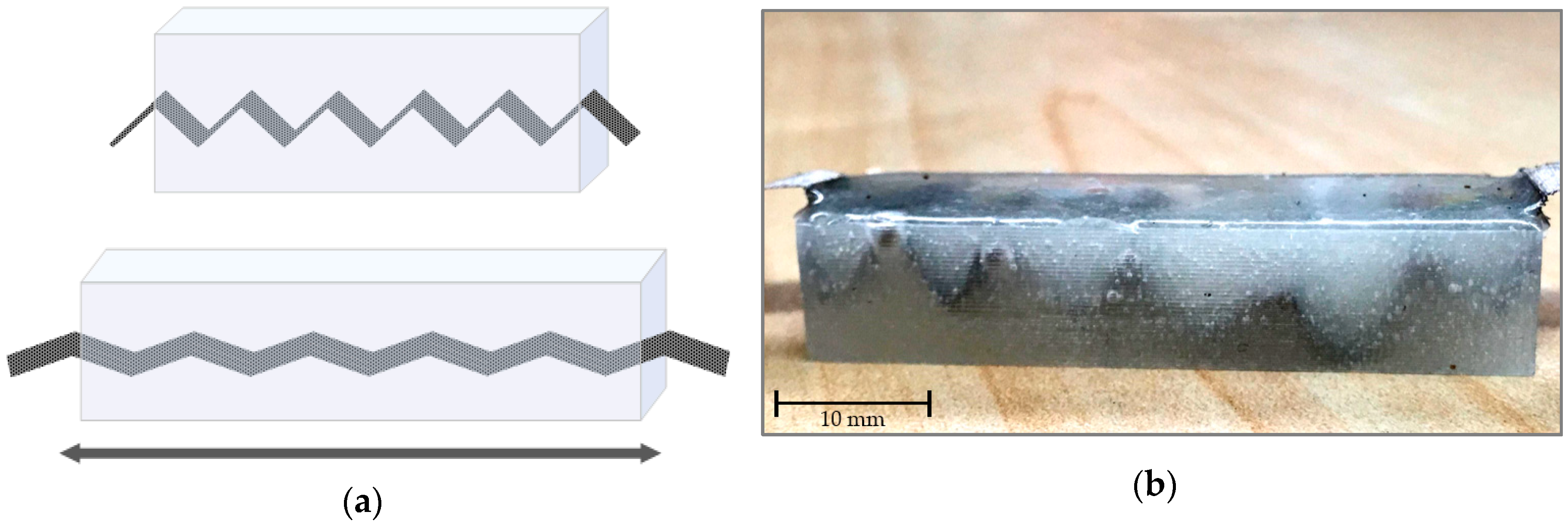
The first continuous fabric pattern tested used an accordion fold, creating a compliant ladder-like structure similar to the bellows of an accordion. Using the Woven Conductive Polyester Fabric, 5 mm × 10 mm strips were laser cut and folded into twenty 5 mm sections. This type of fold could reduce the length of the heater by up to 500%. These accordion heaters were then placed in 50 mm × 10 mm × 10 mm silicone samples without ethanol, pre-folded to allow for the folds to stretch with the actuator’s actuation as in Figure 4.
While this heater maintained a constant electrical connection, it was difficult to manufacture, as the accordion shape would shift around and unfold as the silicone was poured into the mold. Mechanically, the design performed well, as the silicone and element sample would be able to stretch 63% of its original length, only 50% less than pure silicone. A potential issue of this design is that the edges of each crease would become a stress concentration, increasing the likelihood of mechanical failure. Additionally, this design was inadequate for providing enough electrical resistance, averaging 0.4 Ω while the required resistance is between 10 Ω and 30 Ω. Higher resistance designs were considered for the Woven Conductive Polyester Fabric and other lower surface resistance rated fabric options.
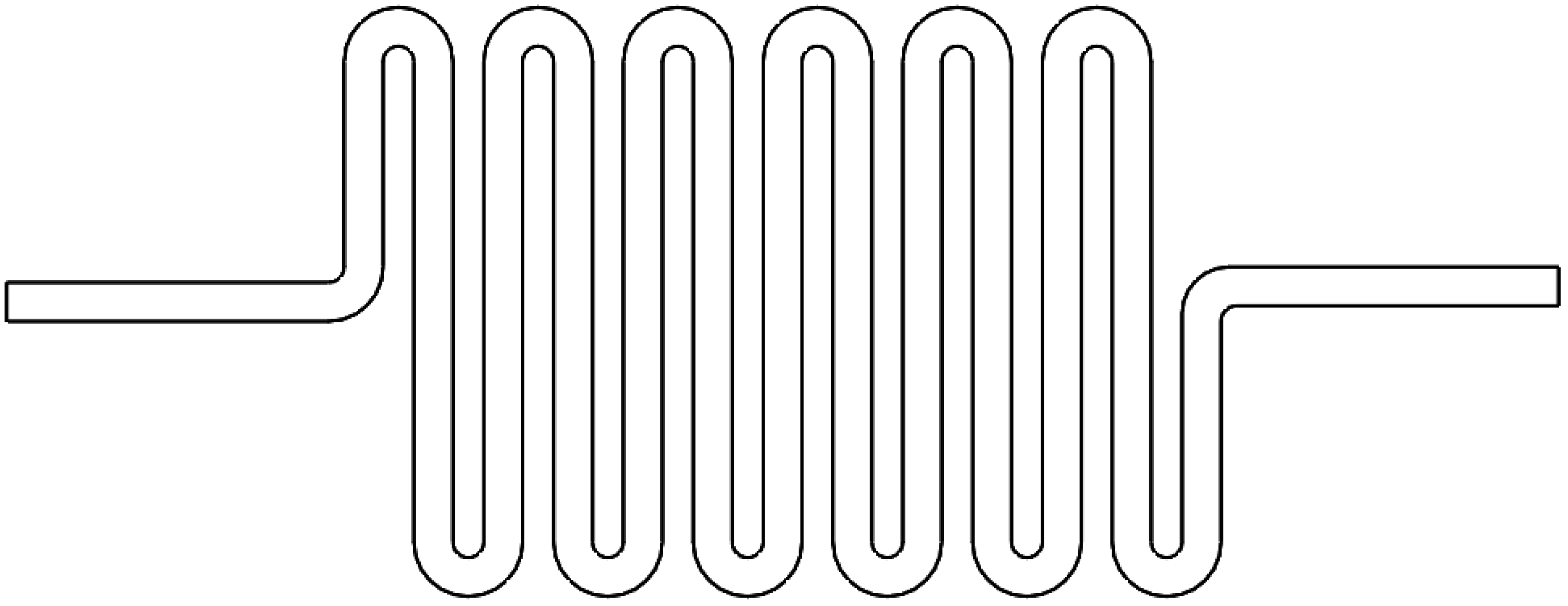
3.1.2. Resistive Track Fabric Patterns
To increase the resistivity of heating elements, long tracks of fabric were cut using the Full Spectrum P-Series Professional CO2 24 × 16 laser cutter. Maximizing the electrical resistance was based on adjusting the geometric parameters of the fabric track, as shown in Equation (1):
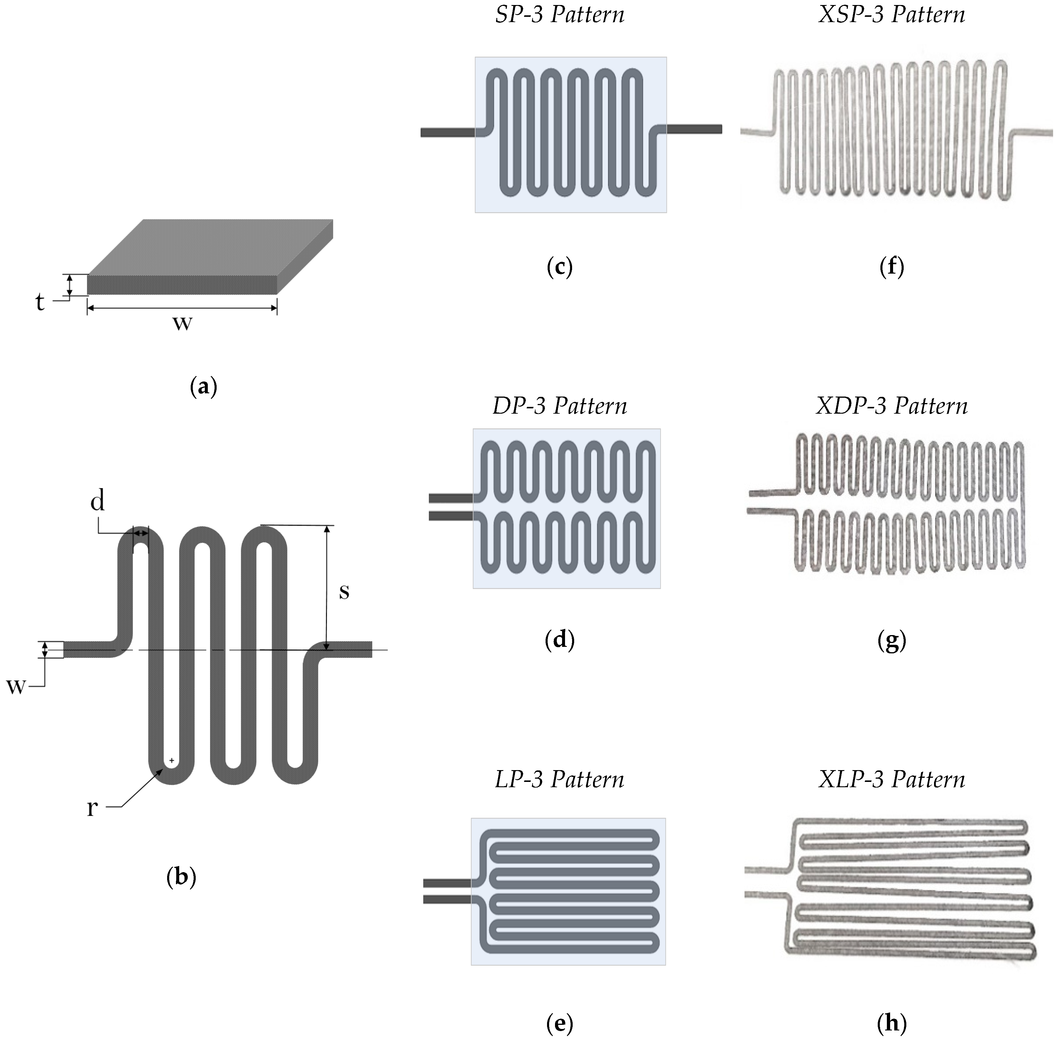
where R is the resistance of the resistor in question, is the resistivity of the resistor material, L is the length of the resistor, and A is the cross-sectional surface area of the resistor. Improving the electrical resistance of the fabric heater requires that the length is maximized, while the cross-sectional area is reduced. Since the thickness (t) of the material is fixed, the reduction of the cross-sectional area would depend on reduction of the width (w) of the heating element track, as shown in Figure 5a.
Manufacturing these track patterns proved to be a challenge, as the fabrics would burn while laser cutting if the settings were not properly calibrated or if the fabric was too thin. In the case that the fabric did burn, the material would crumble and split into pieces, making it unusable. The optimal track thickness and spacing was determined by successive test iterations to maximize electrical resistance and not burn while cutting for the woven conductive polyester fabric.
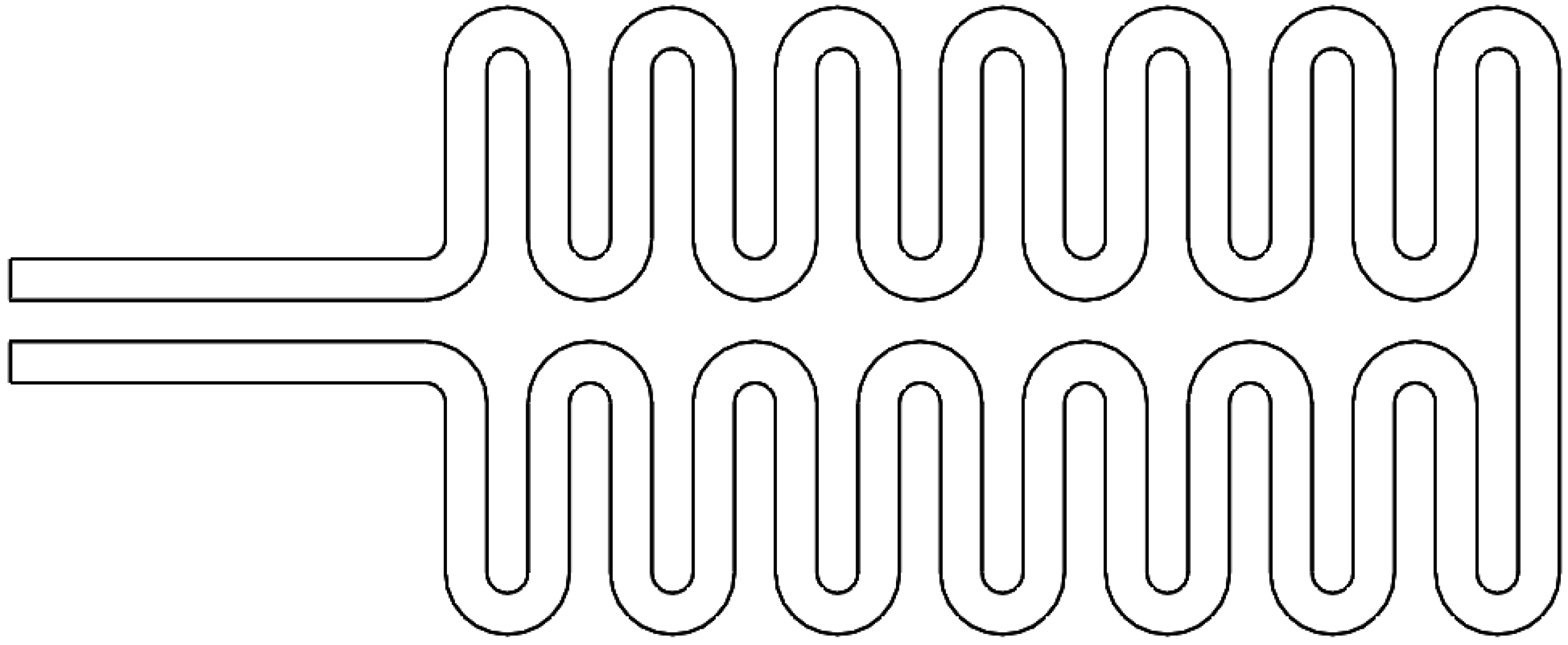
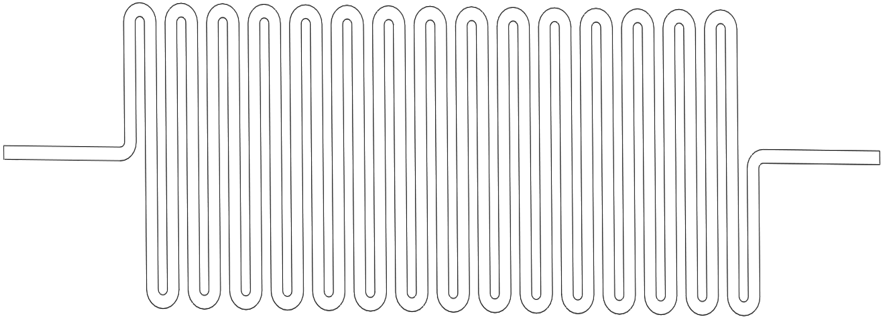
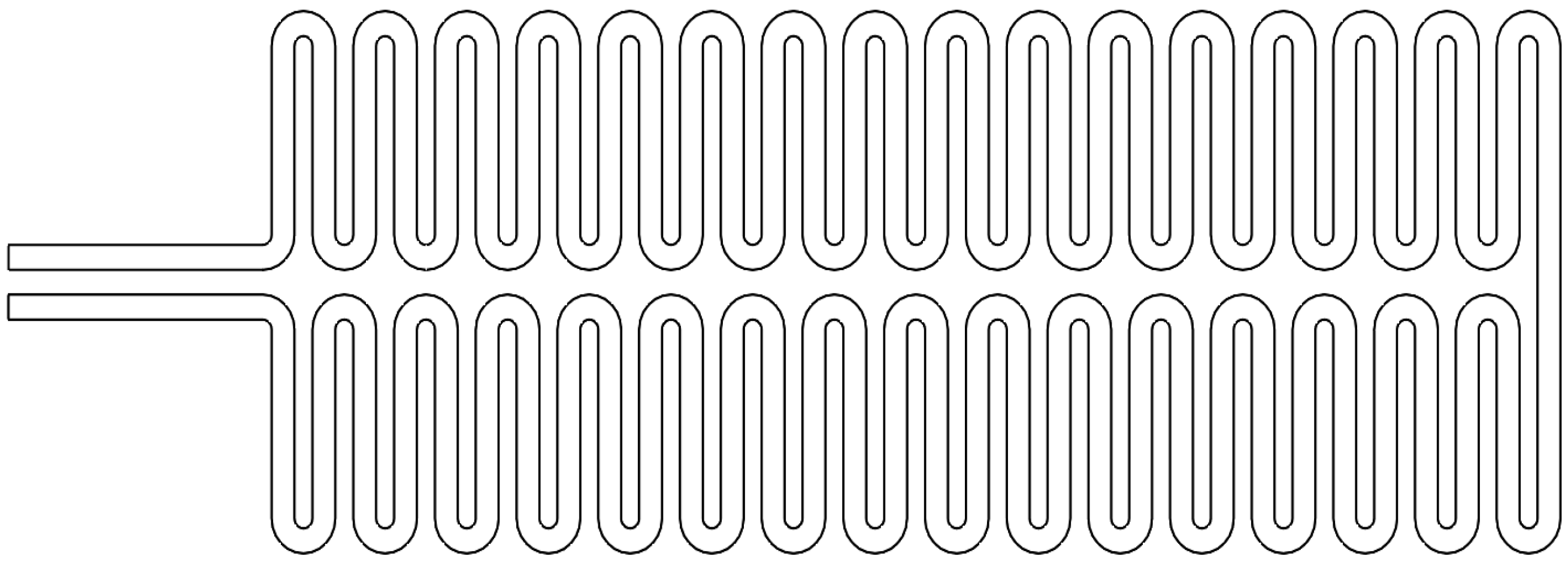
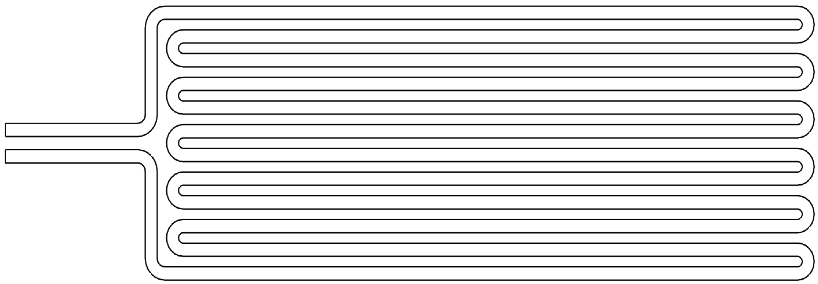
Three different types of track designs were created and implemented in silicone samples to test for flexibility and electrical resistance. These designs use a winding track pattern with filleted corners to reduce stress and thermal concentrations that would arise from sharp corners, as in Figure 5b. Each design was constrained to an area of 70 mm × 50 mm, giving enough clearance around the edges to ensure the heating element is completely enclosed. The geometric parameters of each design in Figure 5c–e are outlined in Table 2. These resistive track patterns are shown in detail in Figure A9, Figure A10 and Figure A11. Each type of design is given a multi-letter organizational acronym describing the nature of the design, as well as the material code number from Table 1.
In addition to 70 mm × 40 mm patterns, large 140 mm × 60 mm Single Pass, Double Pass, and Lengthwise Pass patterns were made to raise the electrical resistance of the Woven Conductive Polyester Fabric heaters to around 30 Ω, closer to the intended resistance range. These larger patterns are shown in Figure 5f–h and are dimensioned in Table 2, where they are given names with an “X” in front to denote their extra-large size. These larger fabric resistive track patterns are shown in detail in Figure A12, Figure A13 and Figure A14. These large fabrics were difficult to manufacture and handle since they were easily ripped or tangled. It was found that wedging these pieces between acrylic sheets would help to flatten out these patterns and maintain the windings when transporting the heater.
These heaters were manufactured on the Full Spectrum P-Series Professional CO2 24 × 16 laser cutter using 55% speed and 10% power, running 2 passes. When being set up on the laser cutter, the fabric could either be taped to a backing plate (such as acrylic) or placed directly on the cutting bed. These fabrics were carefully monitored throughout the cutting process to ensure that the laser was not burning the fabric.
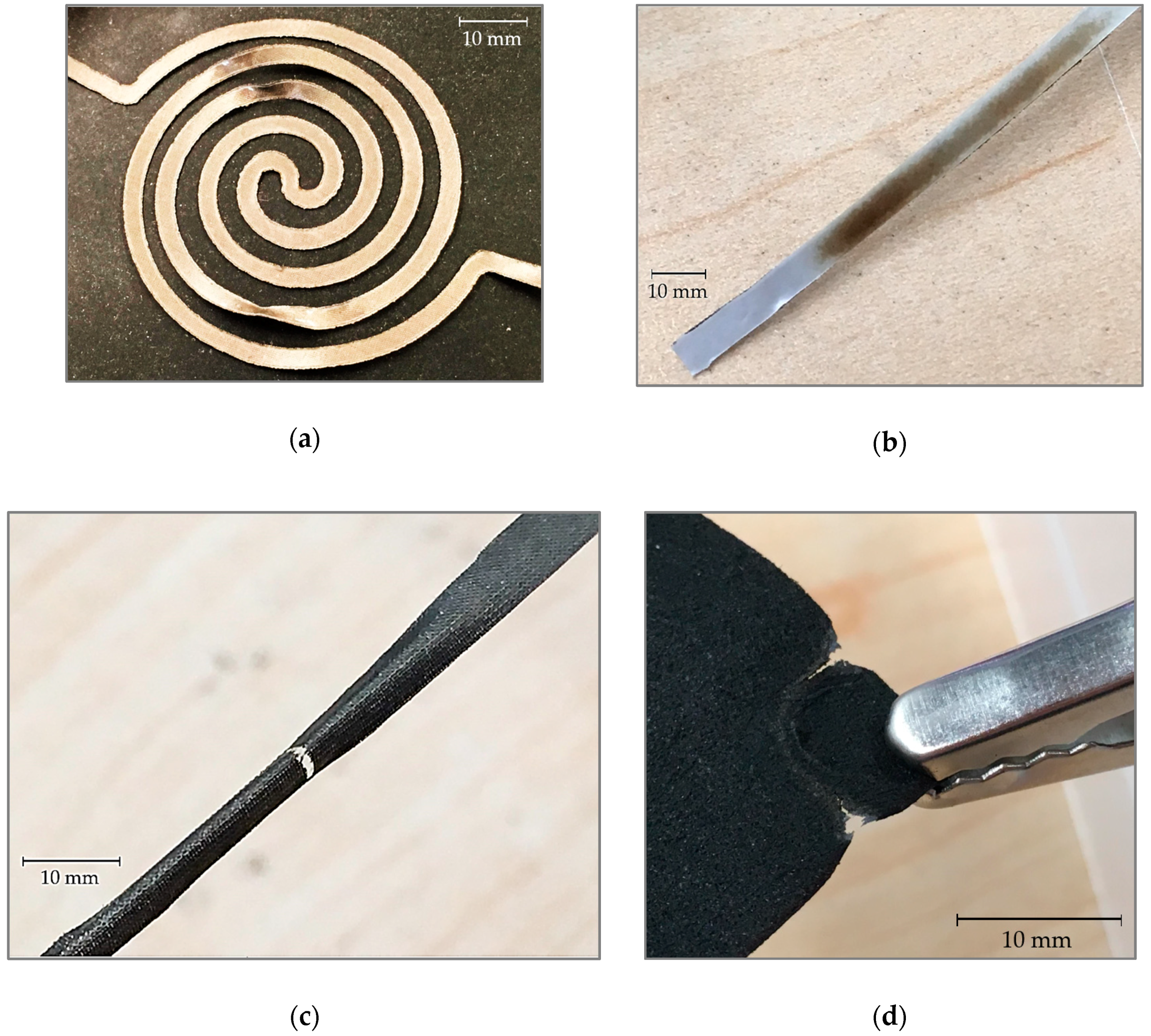
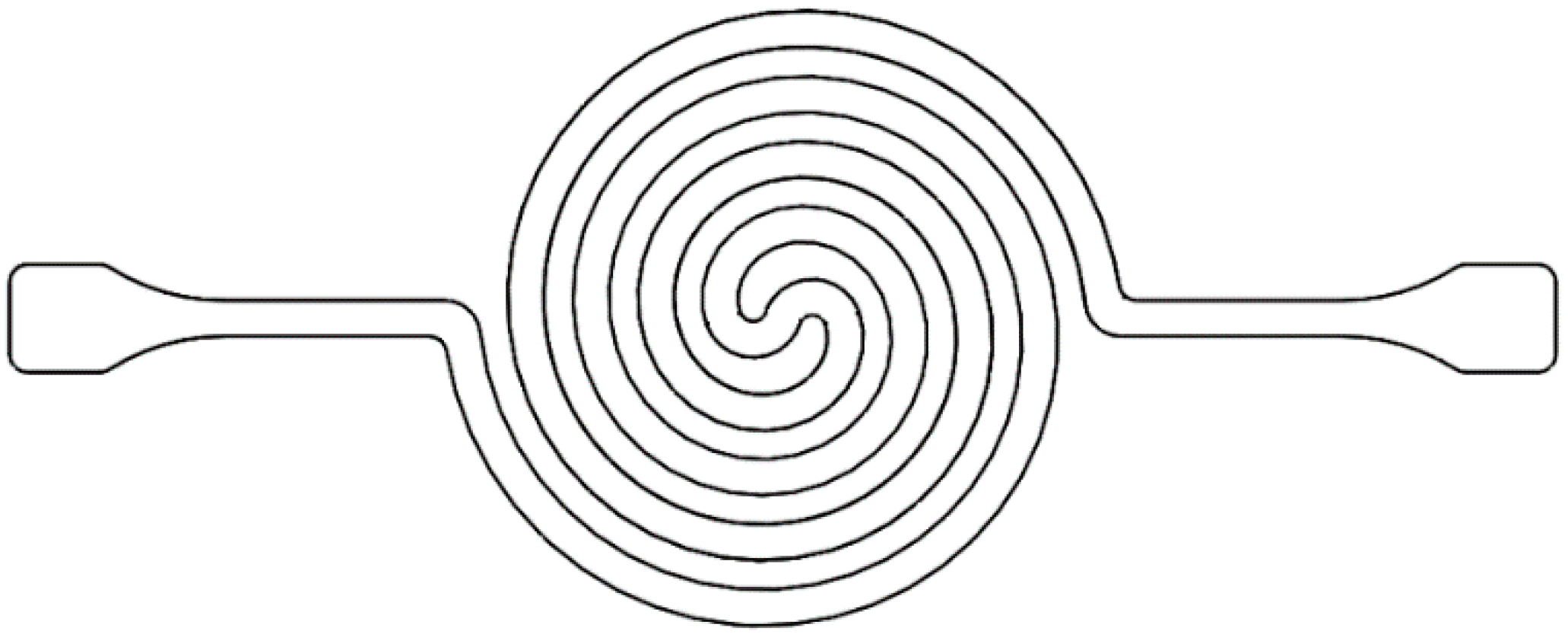
3.1.3. Cubic Actuator Spiral Heating Pattern
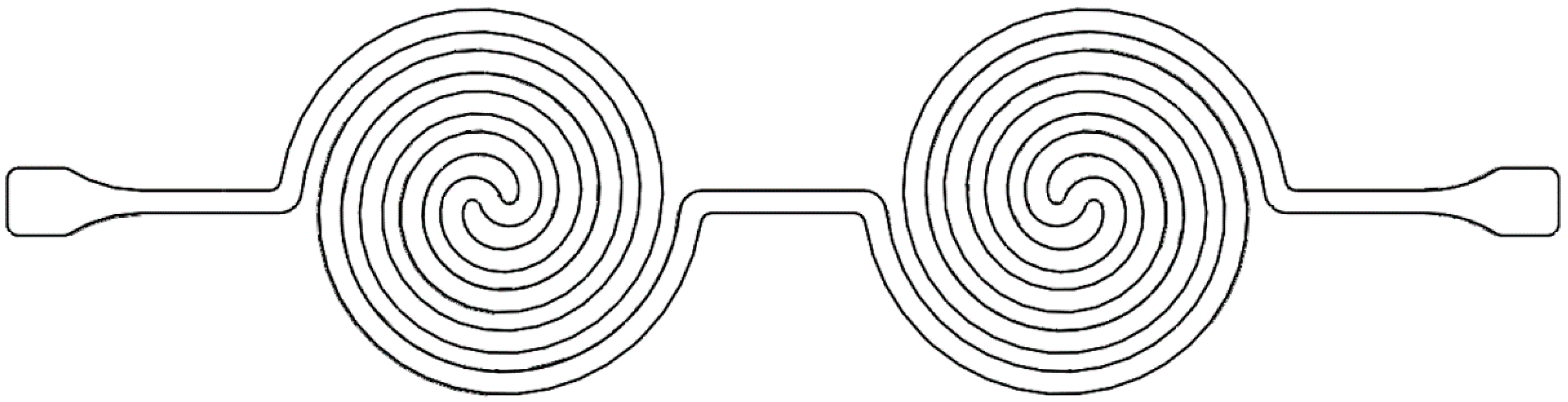
A different type of fabric heater pattern was designed for a 50 mm x 50 mm cubic actuator, using a spiral design to increase the resistance and distribute heat more effectively. Both a single spiral and a double spiral pattern were designed, of which the double spiral is to be used in cases where higher electrical resistance is required. These spiral patterns are shown in Figure A15 and Figure A16. Additionally, the double spiral allows for more even heating, subdividing the actuator material to be heated into smaller sections (Figure 6).
These fabric heaters were laser cut on the Full Spectrum P-Series Professional CO2 24 × 16 laser cutter from the polyester tape, as well as Ni-Cu-Ni double-sided fabric tape, using 65% speed and 15% power, completing the cut in one pass for both materials. The sizing of these heaters is given in Table 3.
3.1.4. Kirigami Heater Design
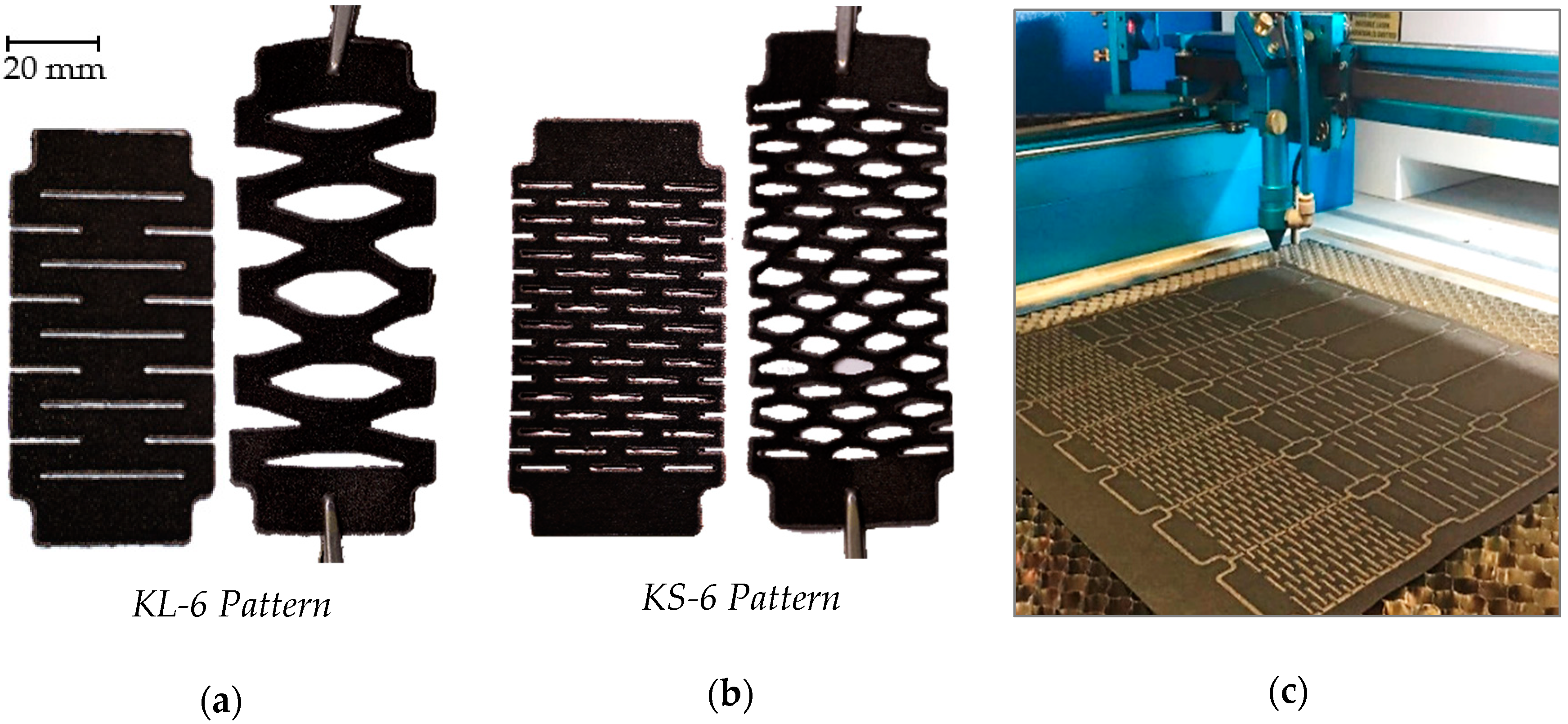
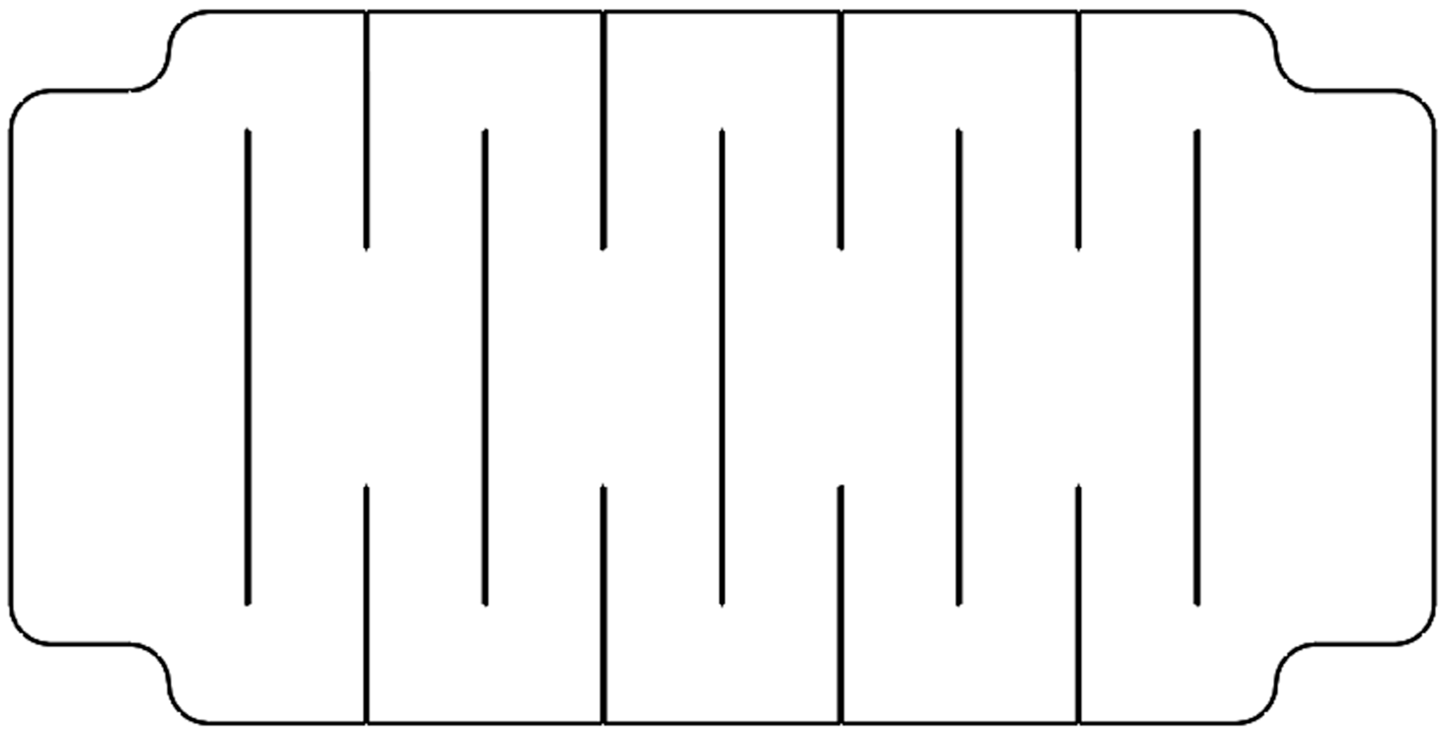
Kirigami is a form of paper art in which cuts and folds are used to create complex patterns and shapes with the material. The cutting technique can be used to create compliance in rigid materials, such as paper and woven fabrics, allowing for a material to stretch over 200% its original length or compress over 80% of its original length [21]. This form of material compliance can be applied to stretchable electronics, such as in solar cells, energy storage devices, and even power circuits [13,21]. Using the Thunder Laser Nova 35 laser cutter (Figure 7c), kirigami designs were cut out of the Thermionyx nonwoven polyester/nylon 6 fabric to fit within a 70 mm × 50 mm area.
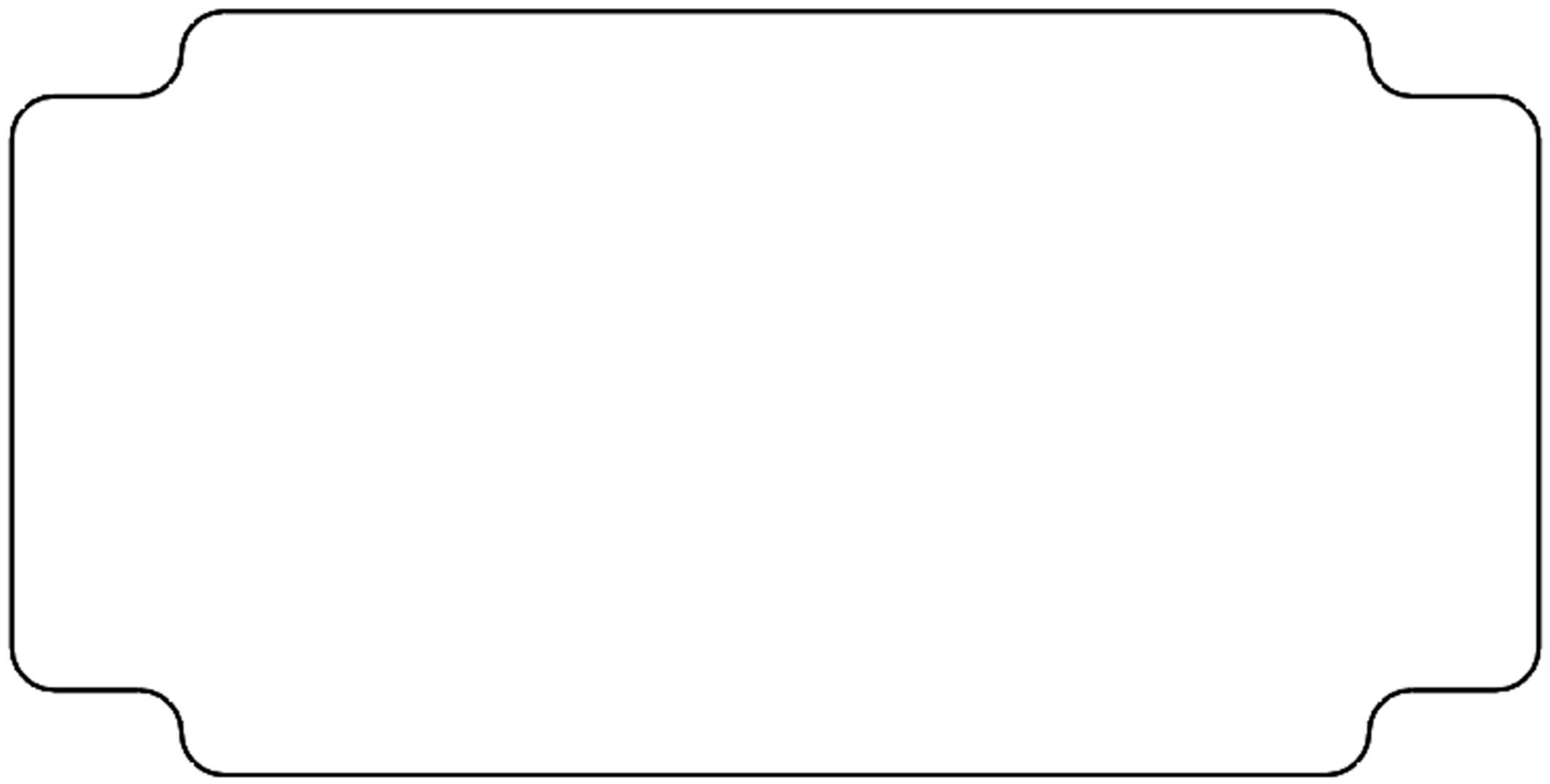
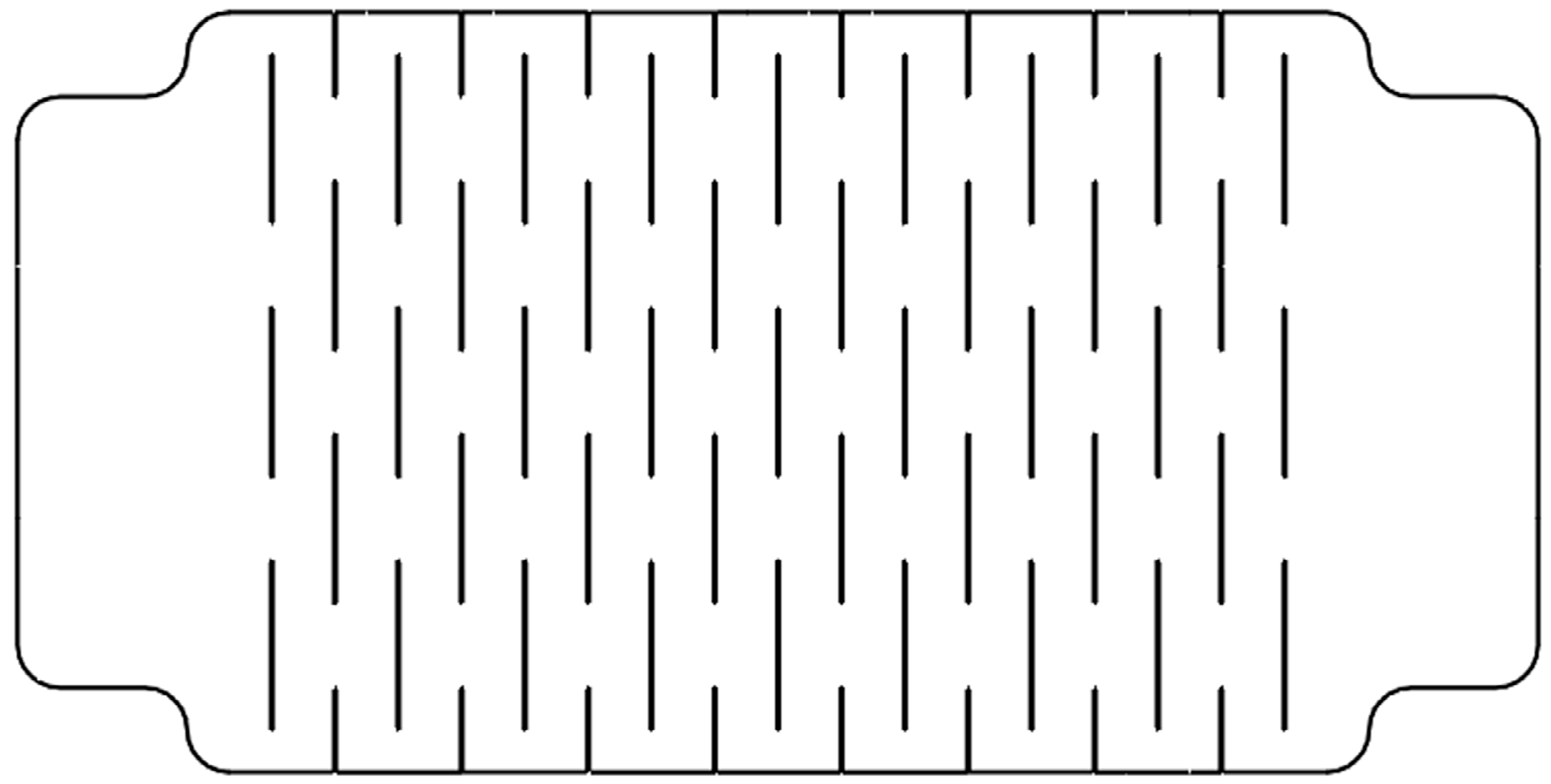
Two variations of the kirigami pattern were created, one with multiple small cuts (KS-6), and one with fewer, but longer (KL-6) cuts, as shown in Figure 7a,b. Additionally, blank Thermionyx patterns (KB-6) were cut to the same outline of the KS-6 and KL-6 design, but do not include any of the cuts, to serve as a basis of comparison against the aforementioned kirigami designs. KB-6, KL-6, and KS-6 are shown in detail in Figure A17, Figure A18 and Figure A19 respectively.
It was determined through multiple iterations that the outer side cuts on both fabric designs need to be at least 50% the size of the central cut(s), to allow for sufficient mechanical compliance. It was determined through preliminary stretching experiments, conducted by hand stretching and a ruler, that the larger cut pattern could permit strains of 43.06% ± 6.99% while the smaller cut pattern could permit strains of 30.56% ± 3.21%. Additionally, it was found using the Fluke 117 True RMS multimeter that while increasing the size of the cuts increases compliance, it also creates a sharp increase in electrical resistance of the heater, as the cross-sectional area becomes smaller at the intersecting points in the design. This effect on the electrical resistance was taken into consideration while finalizing the design of these heaters.
3.2. Fabric Heater Electrical Properties
3.2.1. Sample Strip Resistance Comparison
Initial tests were conducted on each material in order to compute the resistivity of each selected material. Using the Fluke 117 True RMS multimeter, the resistance of a predetermined standard-sized strip of 140 mm × 10 mm was measured for each material, shown in Table 4. From this initial trial, two conclusions were drawn. First of all, the PCB Pyralux foil and the aluminum shielding foil might not provide sufficient resistance to perform as a resistive heater. Additional tests (outlined in Section 3.2.2) were conducted to determine the viability of using these metal foils for a resistive heater. Secondly, the Thermionyx fabric is two orders of magnitude higher in resistance than the other materials on this list, which means it will require more voltage than lower resistance materials to produce the same amount of heat. While it will be difficult to create a resistive track pattern within the preferred range of 10 Ω to 30 Ω with a material of as high a resistance as this, according to the manufacturer, this fabric was primarily designed to be used in heating applications as a highly resistive Joule heater. Therefore, a different type of heating pattern will have to be designed to meet the resistance requirements for this high resistivity material. To counteract this material’s high resistivity, this heating pattern will have to have wider cross sections and be shorter in length, according to Equation (1). Another way to reduce the resistance to the desired level, these Thermionyx fabric heaters can be placed in parallel to reduce the total resistance.
3.2.2. Electrical Resistivity of Selected Materials
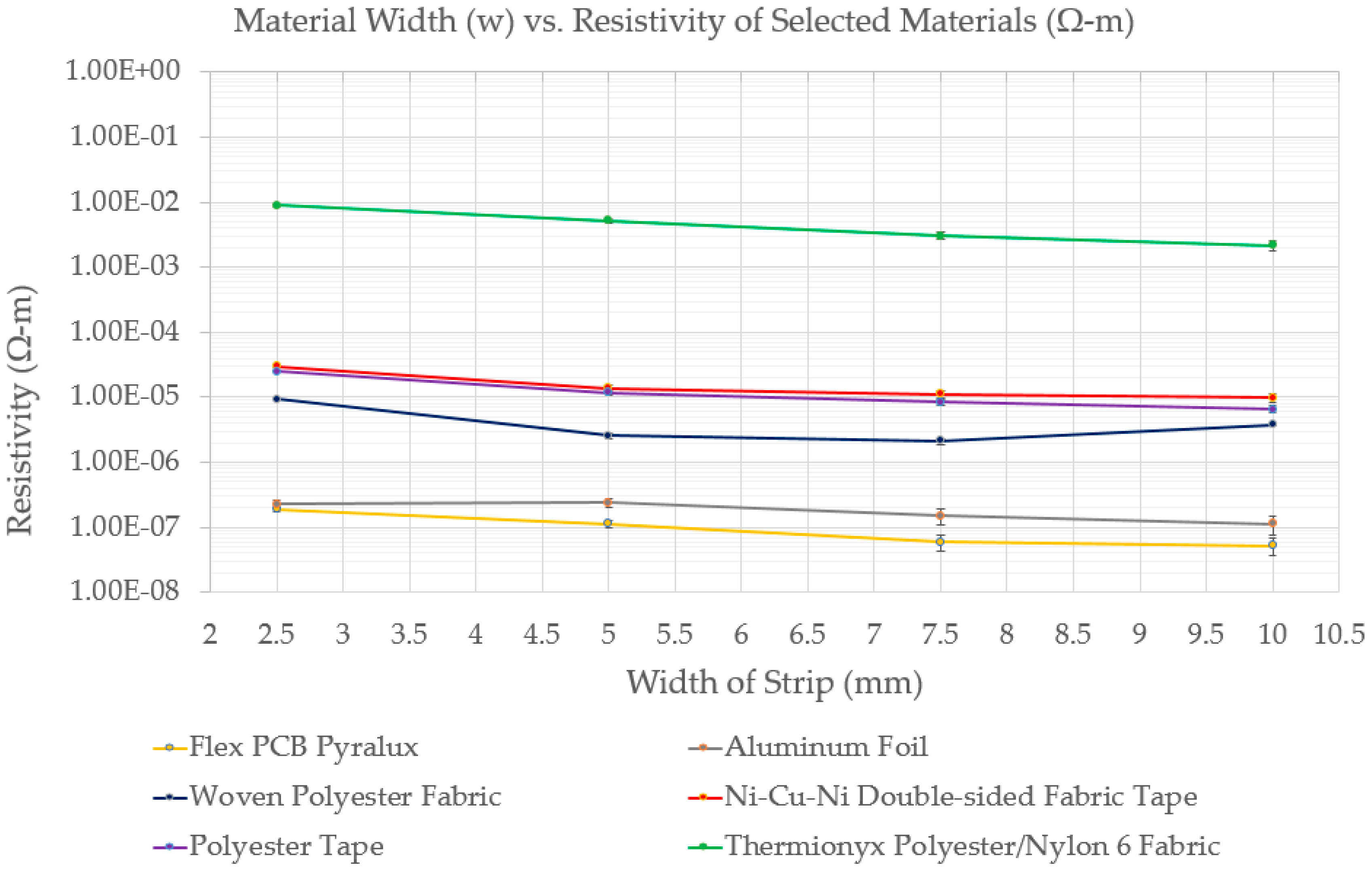
To accurately measure the resistivity of each material, 150 mm strips of each material were cut with widths of 2.5 mm, 5 mm, 7.5 mm, and 10 mm. The measured resistance was then inserted into Equation (1) to solve for the electrical resistivity (Ω·m). Figure A2 shows the average resistivity of each sample width for every material. The overall average resistivity of the samples from 2.5 mm and 10 mm is given in Table 4, including the resistivity of the Ni-Cr wire for a baseline measure.
As noted in Figure A2 and Table 4, both the Flex PCB Pyralux foil and the aluminum foil are a full order of magnitude below the other fabrics in terms of resistivity. As a result, both the Flex PCB Pyralux and the aluminum foil were ruled out as viable options for the heating element. Even when the highest resistivity foil strips tested (2.5 mm wide) were connected to the DC power supply, the FLIR C2 thermal camera was unable to detect a noticeable increase in temperature. This is because the low electrical resistance of the strip and the current limit of the power supply (1 A) results in very low power input, according to Ohm’s law. As a numerical example of the difference in resistance, the woven conductive polyester fabric and the polyester tape 150 mm × 2.5 mm strips held a resistance of 1.42 Ω ± 0.104 Ω and 3.56 Ω ± 0.338 Ω respectively, while the Pyralux and aluminum foils only held resistances of 0.026 Ω ± 0.002 Ω and 0.028 Ω ± 0.0036 Ω respectively.
3.2.3. Heating Element Electrical Optimization
As demonstrated in Figure A2, it was generally observed that there is a negative correlation between material resistivity and width of the material. These results were used as a design tool to predict the resistance of a resistive track pattern, testing how the chosen material and designated track width would affect the resistance of that heater design. In some cases, the predictions were several orders of magnitude higher the actual design. The inaccuracy of the predictions can be attributed to burning sections of the fabric from the laser cutter (particularly on curves). When placed in the laser cutter, any slight folds or bending of the fabric would create an uneven cutting surface, even after taping the fabric taut onto a sacrificial cutting board. Since the surface was uneven, certain areas at a height closer to the focal point would be more likely to be burned than others. The non-uniform burning on each pattern creates variations in the resistance of each fabric heater. However, precise predictions were not crucial as they were used as design guidelines rather than a direct model.
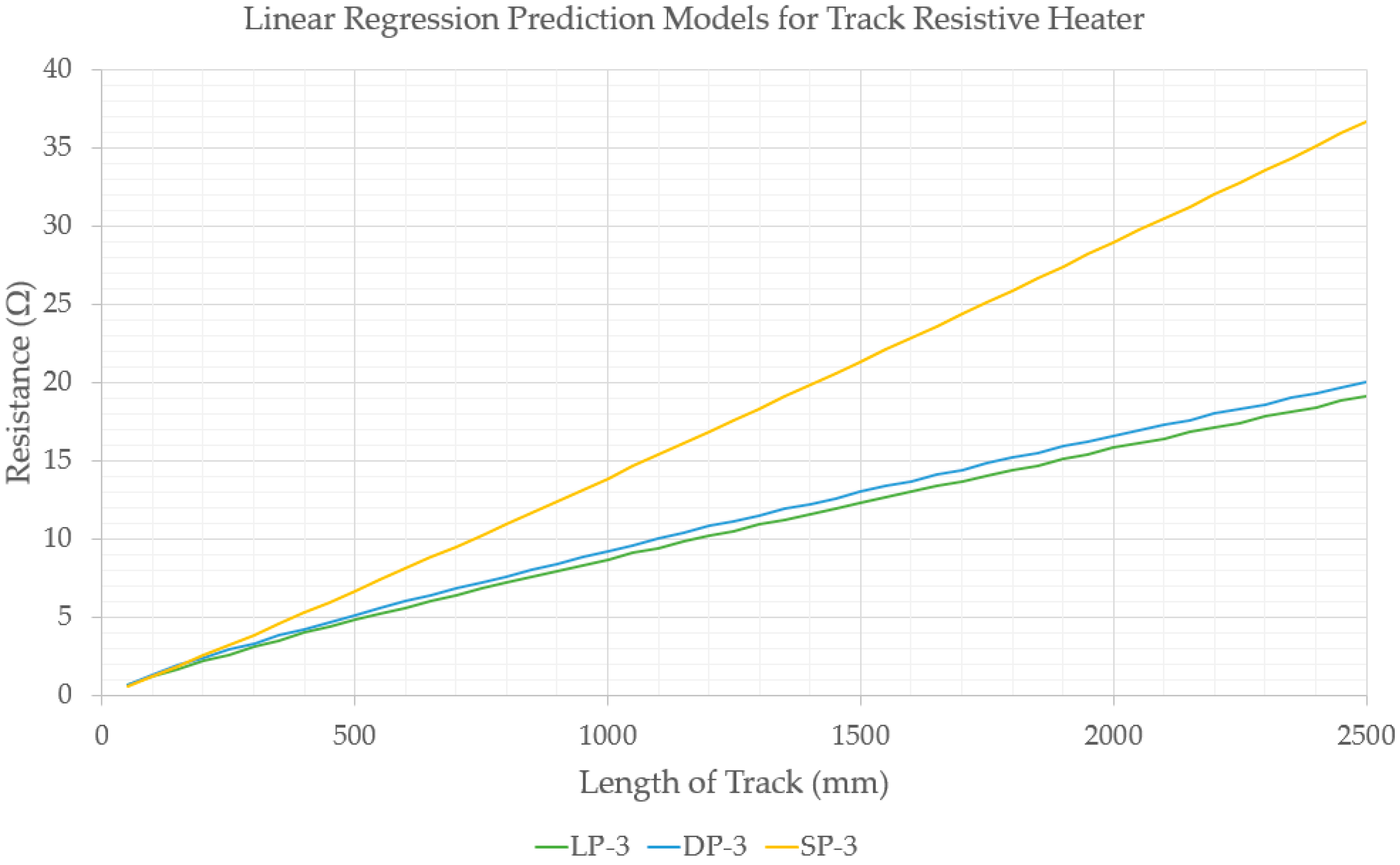
In order to improve one of these heating element designs, successive iterations were laser cut and measured by the Fluke 117 True RMS multimeter. Regression modeling of the collected data were applied to create predictive models on how to efficiently optimize the heating element design, minimizing how many iterations had to be cut and measured. Optimization of each geometric pattern was based on how well each successive geometry performed based on electrical resistance, mechanical compliance, and heating uniformity. Figure A3 is a regression plot created from samples of LP-3, DP-3, SP-3, and their three larger “X” sized counterparts. This plot was a useful tool to calculate the track length of these channel heaters when designing for a specific target resistance. Each of the heater designs from Section 3.1 were evaluated using the Siglent SDM 3055 digital multimeter to attain an average resistance for each heater and to compare against the estimated resistance values. Results are shown in Table 5.
Most of the heating elements fell within or around the 10 Ω to 30 Ω range with a usable repeatability. Another quantifiable measure of electrical performance of these heaters was to determine the resistance per unit volume of the soft actuator material of the actuator they are placed in (Figure A4). This gives a measure of the efficiency of the heating element by providing the electrical resistance density, which should correlate to the heating capability of the element within that specific actuator.
As expected, the fabric heaters made of the highly resistive Thermionyx (KS-6 and KL-6) have a high resistance per unit volume density than the other heating elements. This means that these heaters will require more power than other heaters to actuate an actuator of the same size, as power and resistance are directly proportional. It was also noted that while the larger track resistive heaters (XSP-3, XDP-3, XLP-3) have a higher resistance than their smaller counterparts, they are not considerably more efficient.
3.2.4. Effect of Ethanol on Electrical Resistance
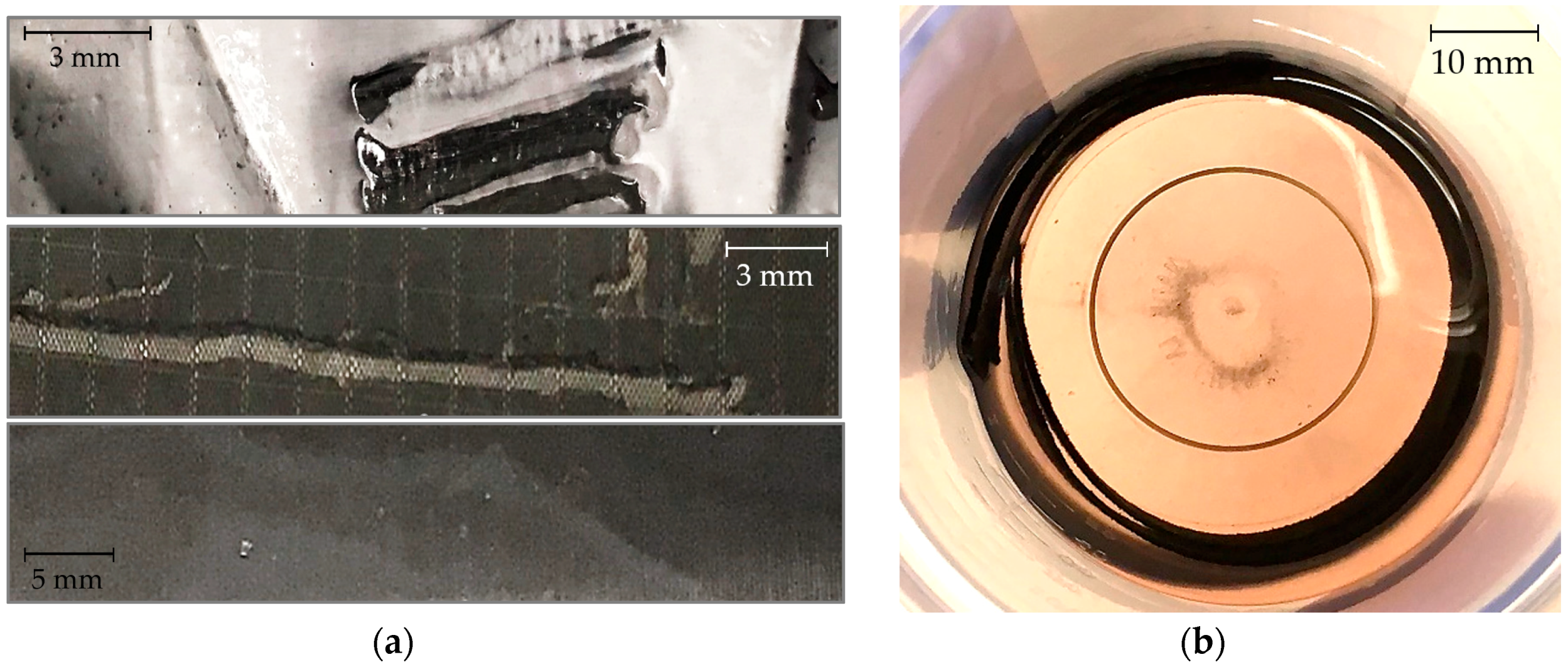
Any kind of heating element placed in this type of soft actuator will have to withstand chemical breakdown from prolonged exposure and absorption of ethanol. To study these effects, 100 mm × 10 mm strips of each material were placed in 40 mL of ethanol and left to soak for one week. After the week ended, the Fluke 117 True RMS multimeter was used to measure the change in resistance of each sample from before it was immersed to after a full week of immersion. Several phenomena were observed once the samples were removed. Figure A5a shows the breakdown of the adhesives on several of the materials, in which patches of adhesive eroded off and could be scratched off. It was also noticed that the Thermionyx fabric reacted with the ethanol, turning it from clear to a light rust color and displaying fabric particulate at the bottom of the container, as seen in Figure A5b. Prolonged immersion in ethanol generally showed an average negative correlation between electrical resistance and time. The percentage change in electrical resistance after 7 days of ethanol submersion was: Pyralux 0%, aluminum foil +25%, woven polyester fabric −22%, Ni-Cu-Ni double-sided fabric tape −56%, polyester tape −13%, Thermionyx fabric −19%. A large standard deviation was exhibited from these results, showing that the effects of ethanol are not clearly definable and will have to be further examined.
3.3. Thermal Analysis of Heating Elements
Both the heating element designs and the materials themselves must undergo thermal testing to ensure that a stretchable fabric heater can effectively power soft actuators. These heaters must be able to reach at least 80 °C to induce vaporization of the ethanol micro-bubbles in the silicone matrix to allow for actuation. Additionally, this heating must be evenly distributed throughout the actuator so that the actuator expands evenly. And lastly, the heater must be able to quickly and repeatably heat the actuator and actuate it for as many cycles as possible.
3.3.1. Material Operating Temperatures
While the minimum temperature to begin actuation in the actuator is 80 °C, the heater itself must be able to withstand higher temperatures to allow for faster heating of the actuator. A higher temperature resistance can provide extra headroom for the material, as there will be no precise way to directly control and limit the temperature of the heater once it is embedded in the actuator. Each material was cut into a 10 mm × 2.5 mm strip and individually connected to the Haitronic HPS605D DC power supply using alligator clips. A constant voltage was applied to each strip such that approximately 1 A of current flowed through the material until it shorted. The FLIR C2 thermal imaging camera was used to monitor the maximum temperature of the material while it was heating and right before the material shorted out. Table 6 outlines the burnout temperatures of each of the materials employed. The Flex PCB Pyralux and aluminum shielding foil were no longer included in these experiments as their low resistance would require a very high current to reach at least 10 W of power.
The burnout temperatures and maximum power input values were all approximations, as the exact temperature at burnout could not be instantaneously recorded with the setup used. These temperature approximations are based on several fabric sample strips, recorded at the time at which the samples started to burn (evaluated on the basis of the smell of burning, discoloration, or appearance of smoke as in Figure A6a,b). It was observed that the burnout temperature and the power input are not correlated, as certain materials that might be able to reach higher temperatures might not be able to heat up as rapidly as other more durable materials. The Ni-Cu-Ni double-sided fabric tape is a very thin material (0.03 mm) and would short if heated too rapidly (see Figure A6c), while the Thermionyx material is significantly thicker (0.6 mm) and much higher in electrical resistance, enabling it to consume more power. However, if the Thermionyx material is heated too quickly, it will start to burn out and short (see Figure A6d). As a general observation, it was noted that the tested thinner materials were more likely to warp or curl from the heat and start burning at lower temperatures than thicker materials.
3.3.2. Rate of Heating per Material
When the heating element is placed in the silicone ethanol actuator, its heating rate will be directly tied to the actuation frequency. The maximum actuation frequency is correlated to the maximum allowable heating rate of the heater. The material limitations outlined in Table 6 define the maximum power input, which can be used to determine the maximum heating rate of each material. Heat output was experimentally tested using 150 mm strips of each material in thicknesses of 10.0 mm, 7.5 mm, 5.0 mm, and 2.5 mm. The following measurements and analysis were performed to achieve a relative comparative estimate the materials’ thermal performance. The strips were heated by the Haitronic HPS605D DC power supply, which applied 1 A of current through each material. Temperature measurements were recorded every 30 s, using the FLIR C2 thermal camera. From these measurements, the change in temperature (ΔT) was calculated to find the rate of heating (ΔT/s) in each material, in units of °C/s. With the rate of heating known, the efficiency of the heater could be gauged by calculating the ratio of the change in temperature to the electrical power added to the system, as in Table 7. With this ratio, the maximum rate of heating (ΔTmax/s) could be found using the power limits from Table 8.
While the Ni-Cu-Ni double-sided fabric tape and polyester tape have a comparable heating efficiency per Watt to the Thermionyx fabric, the latter fabric far surpasses the alternatives in heating performance, due to the material’s capability of maintaining higher power inputs without burning.
3.3.3. Heat Distribution of Heating Elements
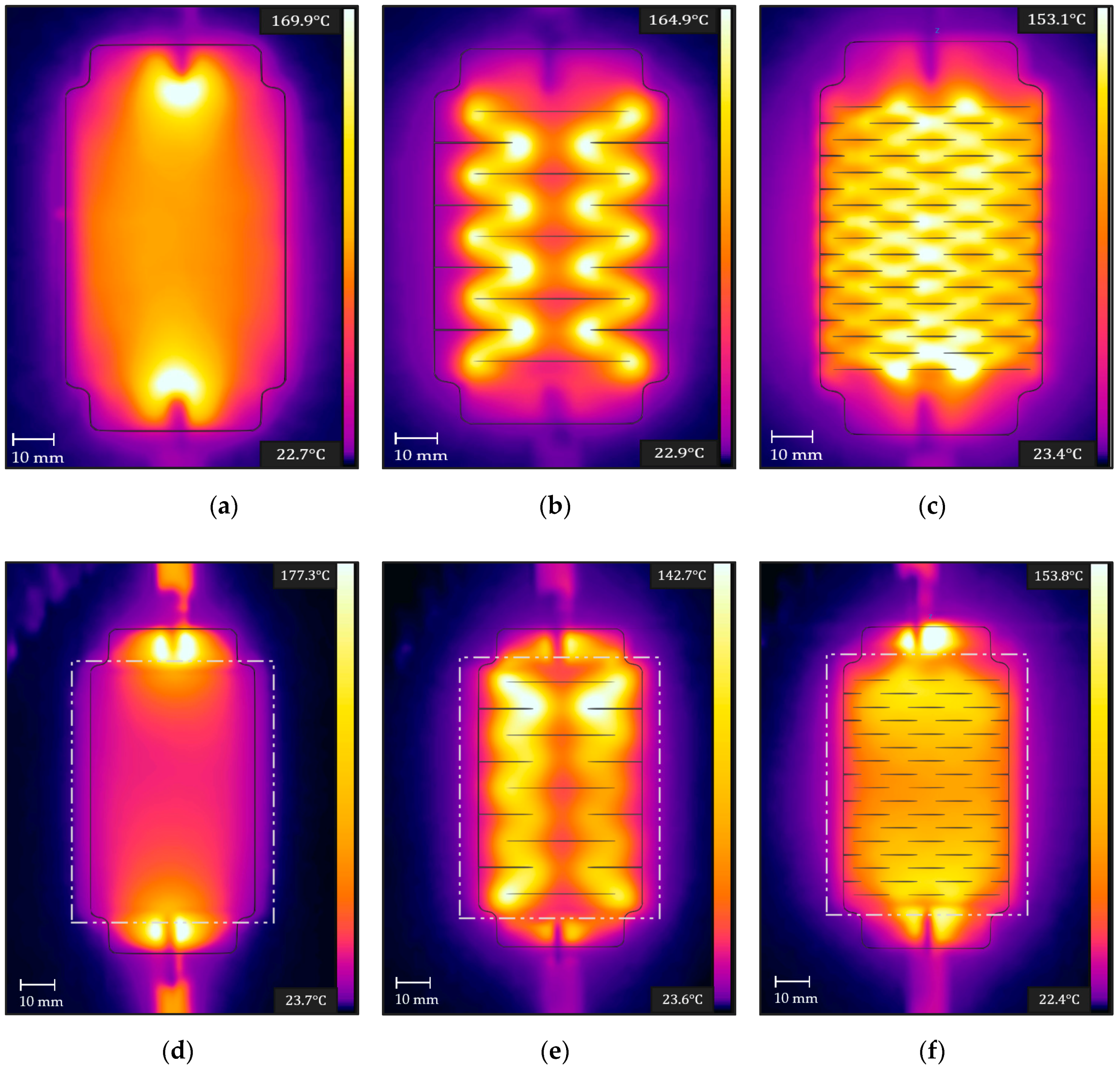
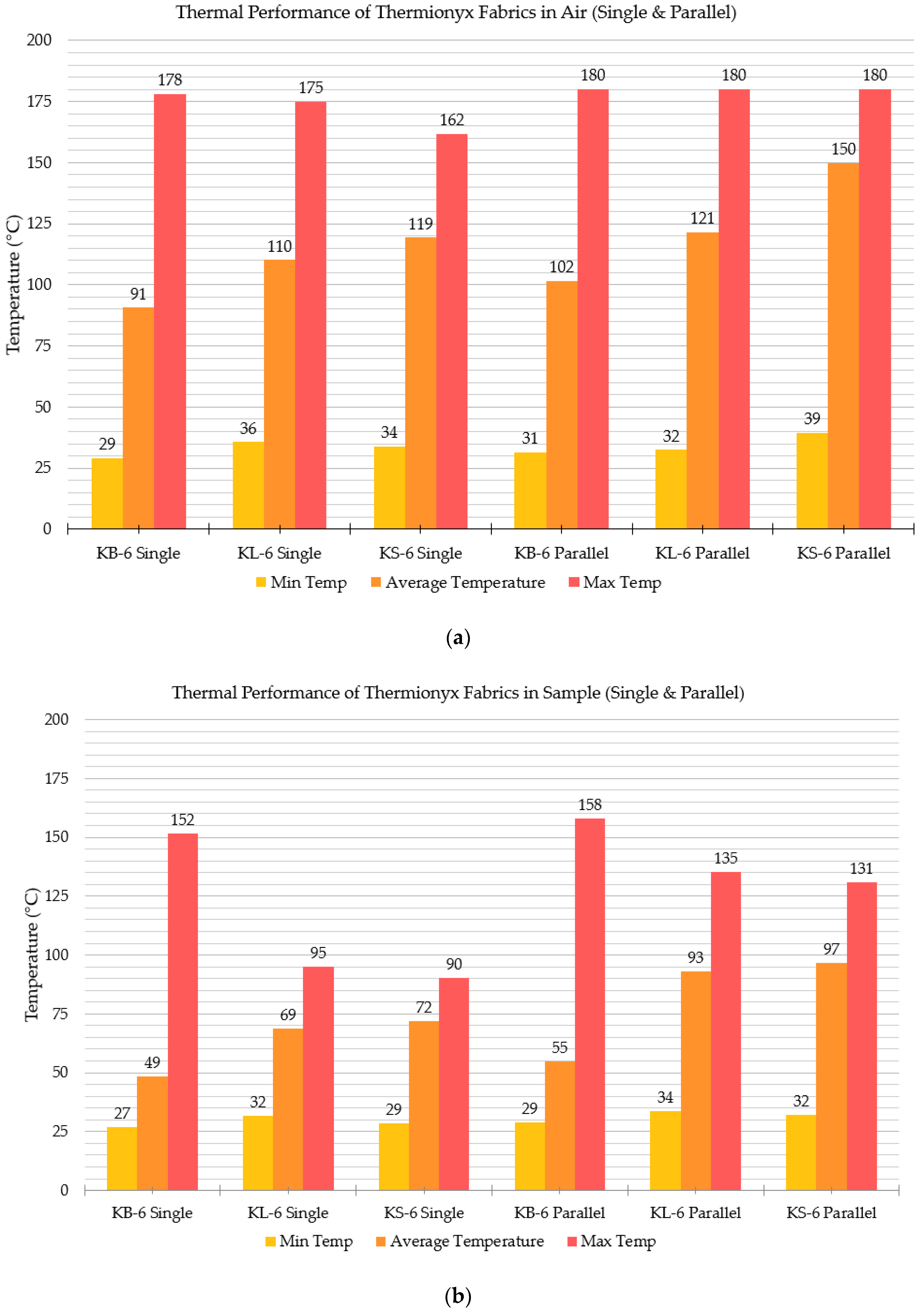
Uniformly distributed heating is crucial for even actuation and for repeatability of actuation cycles. The Ni-Cr resistive coil heaters create thermal concentrations from uneven winding spacing and are limited to how spread out they are within the actuator. Fabric heaters can be laser cut to precise shapes, allowing for repeatability and can span the entire length and width of an actuator, maximizing uniform heating. The KS-6 and KL-6 heating patterns were developed to more evenly distribute heat compared to a blank Thermionyx fabric heater (KB-6). Figure 8 shows the thermal images (recorded on the FLIR C2 thermal camera) of the three patterns at their maximum temperature. These three samples were heated by the Haitronic HPS605D DC power supply at their maximum power input levels, as described in Table 8 and shown in Video S1.
In the KB-6 design (Figure 8a), current flows directly from one end to the other, with a significant amount of drop off in temperature in the center, going down to 107.1 °C compared to 180.2 °C at the ends. If this fabric is implemented in an actuator, the ends would start to actuate before the middle, due to the uneven temperature distribution. Higher temperatures are brought more evenly through the KL-6 design (Figure 8b) as the current is forced to weave around the large cuts, creating concentrations of heat around each corner. This makes these concentrated areas in the actuator actuate before other sections. Design KS-6 holds the most promise, as the current is forced to flow through many paths, bringing heat through the majority of the fabric. This will allow for even actuation when this material is placed in an actuator.
To measure the thermal distribution of these samples, ten samples of each of the three fabric patterns in Figure 8a–c) were examined in open air as a single resistor and in parallel. Thermal images taken on the FLIR C2 camera were analyzed on the FLIR Tools software, which allowed the images to be analyzed for the minimum and maximum temperature and for computing the average temperature over a selected area. The average temperature was used to classify how well a pattern distributed its heat throughout the actuator. These tests were conducted with a single resistive fabric, as well as two of the same kind of design placed in parallel.
In addition to heating the fabrics in the air, the same heating experiments were conducted by placing the KB-6, KL-6, and KS-6 into 70 mm × 50 mm × 10 mm silicone samples (without ethanol). In these experiments, the FLIR C2 camera was used to measure the temperature of the surface of the silicone sample, with the temperature range and average temperature of the silicone surface recorded and plotted (Figure A7). Figure 8d–f are raw thermal images of the fabric heating up the silicone actuator. Since the silicone actuator retains considerable heat, it required a higher power input to achieve the same heating rate as the fabrics in open air.
On average, the KS-6 fabric heater outperformed the KB-6 and KL-6 in terms of average temperature, meaning it can deliver a more even temperature distribution. The KS-6 held a higher average temperature by 50.3% ± 19% and 10.2% ± 9% in comparison to KB-6 and KL-6 respectively.
3.4. Mechanical Properties
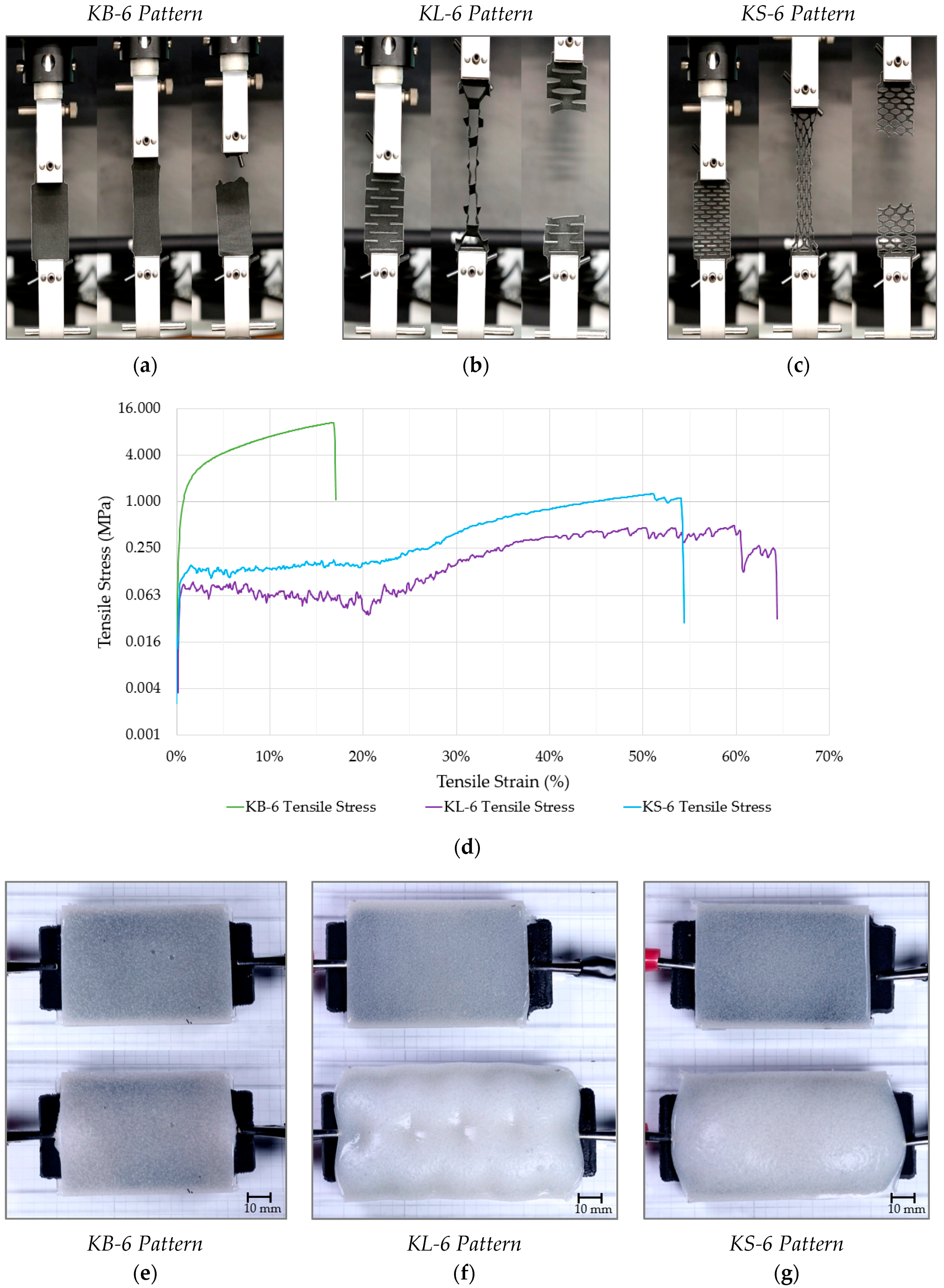
Mechanical testing was conducted on an Instron 5569A table mounted materials testing system with a max load cell capacity of 50 kN using Instron BlueHill software to control the frame. Both the fabric heater itself and the fabric heater in silicone were placed in the test jaws and stretched until failure, pulling the specimen upward at a constant rate of 500 mm/min (Figure 9, Videos S2 and S3). A sample of plain silicone was tested as a baseline for comparison against which the fabric heaters could be compared, evaluating the extent to which they limit the actuator’s stretchability.
From the data obtained from the Bluehill software, the maximum strain could be determined and compared. The maximum extension can be used to determine the strain of each of the tested samples, which will be the variable used to compare the material compliance of each fabric design (Figure 9a–c). The data were processed to create the stress vs. strain plots, shown in Figure 9d.
It was found that KL-6 and KS-6 could withstand 47.9% and 39.3% more strain than the KB-6 fabric heater, which could only handle up to 15.6% strain. The silicone by itself can achieve 101% strain, and the fabric heaters embedded in silicone only limited the strain to 57.7% and 67.6% for KL-6 and KS-6 respectively. It can be concluded that the kirigami fabric designs were capable of producing sufficient material compliance, allowing the silicone to stretch up to 62% of its original strain on average. This geometric compliance will help the soft actuator to actuate as freely as possible, not hindered by the fabric heater.
3.5. Actuation Using Fabric Heating Elements
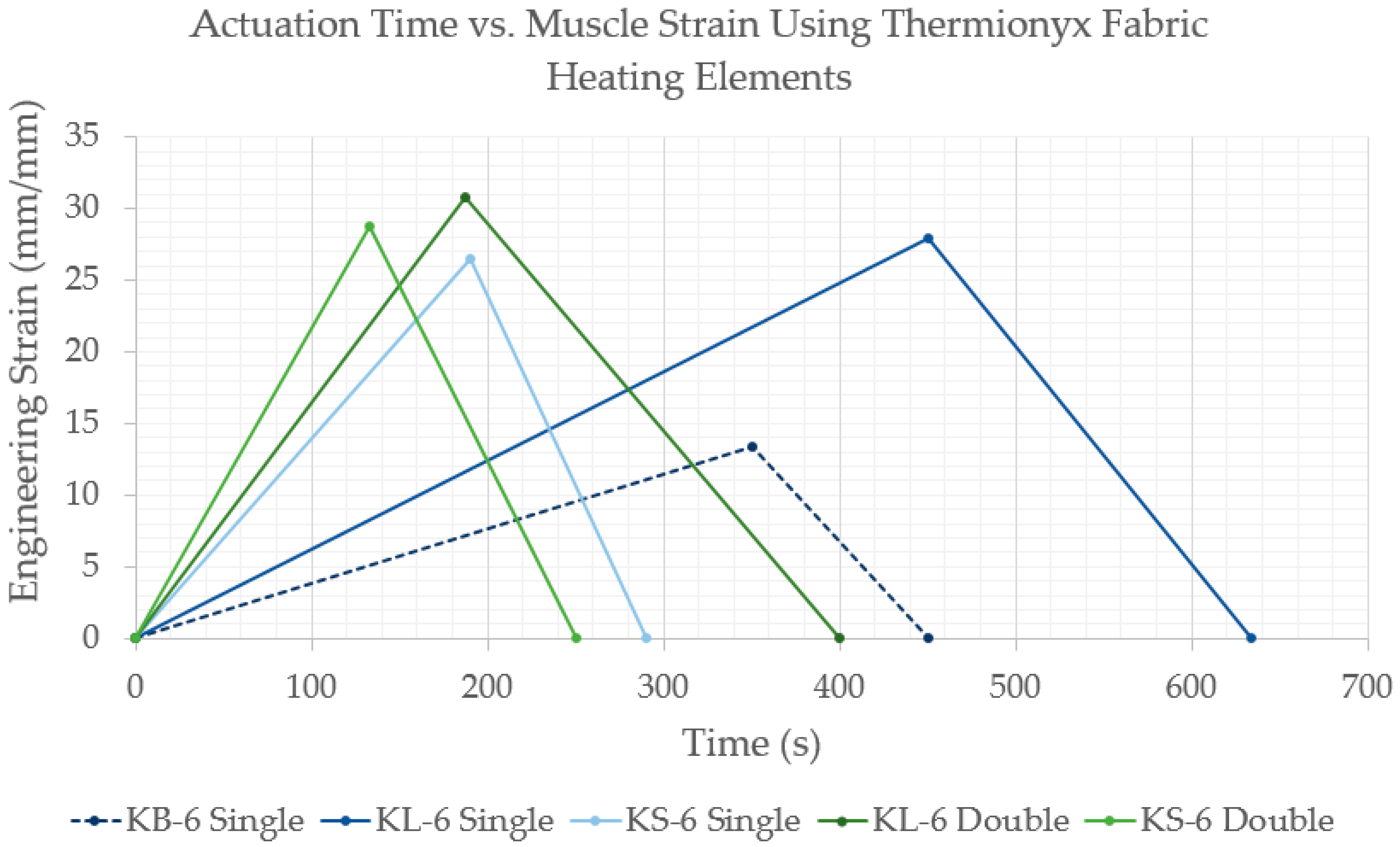
The Thermionyx fabric designs KB-6, KL-6, and KS-6 were placed into actuator material (20% ethanol by volume) as a single resistive heater, or as two of the same type of resistive heater design in parallel. The Haitronic HPS605D DC power supply provided a constant voltage through the conductive fabric, generating heat and inducing actuation, which was recorded with the Canon EOS 80 D (with a Canon EFS 18-135 mm lens) and monitored with the FLIR C2 thermal camera (Video S4). The experiments were conducted on a sheet of clear acrylic with grid paper underneath to provide scale. Each actuator sample was actuated as many times as possible until the fabric burned out or the actuator became exhausted [6]. The actuation temperature range was between 70 °C and 90 °C, denoting the point at which the actuator would begin heating or be allowed to cool. The videos taken by the Canon EOS 80 D were analyzed, recording the duration of each actuation cycle and the maximum expansion of each actuator. The KB-6 fabric design was used as a baseline to compare how well the compliant fabric designs allow the material to expand and how evenly to heat the actuator.
The heat distribution from each fabric design yielded predictable actuation, in which the thermal patterns from Figure 8 were referenced to confirm the section of the actuator that would actuate first and to the largest degree. Figure 9e–g shows the Thermionyx fabric heated soft actuators in the resting position and at the maximum actuation length.
Each actuation pattern closely correlates to the thermal pattern of the fabric heater, such that the actuator begins to actuate first and expands the most in the hottest part of the actuator. In the case of KB-6, the hottest part of the heater is at the ends of the actuator closest to the alligator clips, causing the actuator material to expand the most in these areas, as in Figure 10a. However, the actuator itself was not able to expand since the fabric design constricted the actuator’s movement; only the top and bottom surfaces of the actuator farthest from the restrictive influence of the fabric were able to expand.
The KL-6 design shows actuation primarily around the current paths seen in Figure 8b, allowing this actuator to actuate in a directed uniaxial path. These designs showed the highest elongation of strains, up to 30.7% ± 2.0%, and were capable of performing 2.33 ± 1.15 actuations on average. The fabric heaters would burn out either at the connection to the alligator clip, or internally, as in Figure 10b.
The KS-6 actuation was the most uniform, since the heating was evenly spread by the fabric pattern as in Figure 8c. The actuator would start to actuate in a few small areas locally before combining and actuating as a single unit. An unexpected phenomenon was observed, whereby the local areas of expansion would combine, and the entire actuator would inflate into a shape that resembles that of an overstuffed ravioli, shown in Figure 10c.
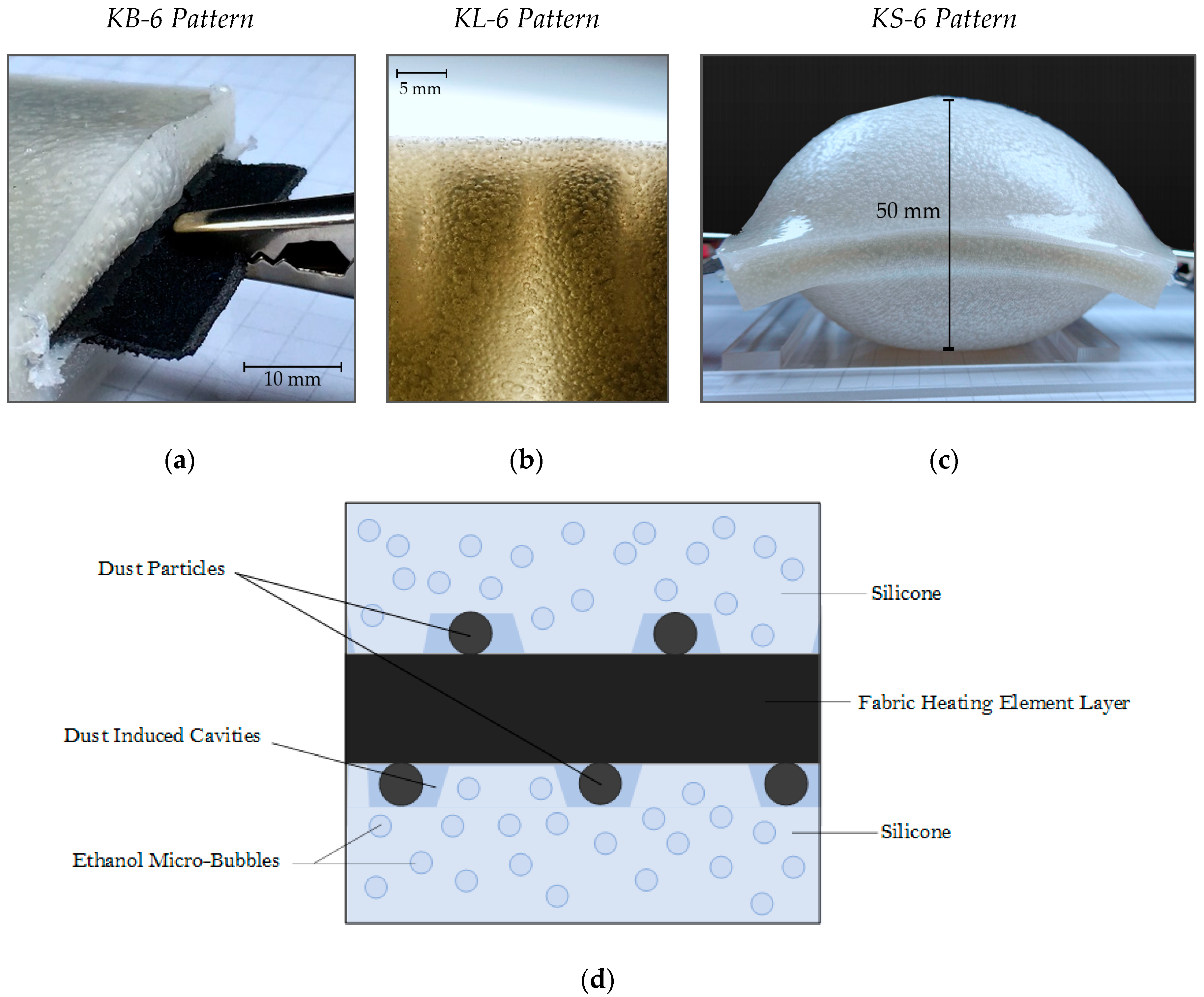
The cause of this enormous expansion is from the exponential combination of micro-bubbles in the silicone, creating a large bladder within the actuator. A theory as to the cause of this internal structural failure is that dust particles remaining from laser cutting create large pockets of ethanol within the silicone (Figure 10d).
When the actuator is heated, these large pockets expand rapidly and combine with the smaller micro-bubbles until the entire actuator is bloated by ethanol vapor. Besides inflating, these actuators produced elongation of strains up to 26.5% ± 1.6% and were capable of performing 2.0 ± 0.82 actuations on average before burning out. The performance of each of the fabric heaters (KB-6, KL-6, KS-6) in the silicone-ethanol actuator is further shown in Figure A8.
3.6. Conductive Fabric Performance Analysis
Based on these experiments, the woven conductive polyester fabric, the Ni-Cu-Ni double-sided fabric tape, the polyester tape, and the Thermionyx nonwoven polyester/nylon 6 fabric proved to be acceptable materials for use as flexible and stretchable heating elements. The Flex PCB Pyralux foil and the aluminum shielding foil had electrical resistivities too low to perform as a Joule heater unless large amounts of power are used. The aforementioned fabrics could be customizable in a laser cutter depending on space, power, and flexibility constraints, making them applicable to a wide range of uses. The material properties of these conductive fabrics are listed in Table 8.
The performance of a heating element can be attributed to how high a temperature it can reach and how long it takes to reach that maximum temperature. For resistive heaters in the same environment, higher power input will yield faster heating. With fabrics, higher power also correlates to a higher risk of the fabric burning out and breaking the circuit. Additionally, the heating rate will be affected by the thermal time constant, which is related to the heater’s mass, heat capacity, surface area, and heat transfer coefficient. Future research will seek fabrics with higher thermal resistance, higher resistivity, and can handle higher power inputs.
5. Conclusions
Using Ni-Cr wires for thermally-induced soft actuation poses challenges for precisely repeatable and automated manufacturing and limit the homogeneity of the heat distribution. In the present work, conductive fabrics were assessed as alternative Joule heaters, due to their flexible nature and ease of laser cutting. The relationships between fabrics’ heating pattern geometries, mechanical compliance and heat distribution were studied and tested on thermally triggered soft phase-change silicone/ethanol actuators. Several fabric designs were analyzed, including accordion folding, resistive tracks, spiral tracks, and kirigami designs (see Appendix C for drawings of each design). Each respective design was optimized geometrically to improve mechanical compliance, electrical resistance, and heat distribution. Material characterization was conducted for each selected fabric to test compatibility for the application as a soft flexible heater, including assessment of thermal limits, electrical resistivity, and mechanical properties.
Of the selected fabrics, the Thermionyx nonwoven polyester/nylon 6 fabric was determined to be the best suited, as it is capable of repeatable heating of up to 195 °C, it has the highest resistivity among the fabrics of 4.83 × 10⁻³ (Ω·m), it is easy to laser cut into customizable shapes quickly and accurately, and it can withstand up to 63.5% strain when in a kirigami design. The kirigami design enabled a soft actuator to elongate up to 30% after 2 min of heating with ~ 30 W of power, 1.5 times faster and 16% longer than just a blank Thermionyx fabric.
In the future work, the effect of the actuator size and shape on fabric-mediated heat-induced actuation will be evaluated. Additionally, fabrics with higher operating temperatures will be examined in hopes of achieving faster heating using higher power input.
Supplementary Materials
The following are available online at https://0-www-mdpi-com.brum.beds.ac.uk/2076-0825/8/1/9/s1, Video S1: Thermal Imaging—Heating Conductive Fabrics.m4v, Video S2: Tensile Testing Fabric Heating Elements.m4v, Video S3: Tensile Testing Fabric Heating Elements in Silicone.m4v, Video S4: Actuation Testing.m4v.
Author Contributions
Conceptualization, M.C., B.X., A.M.; Methodology, M.C.; Validation, M.C.; Formal Analysis, M.C.; Investigation, M.C.; Resources, A.M, B.X., H.L.; Writing-Original Draft Preparation, M.C.; Writing-Review and Editing, M.C., B.X., A.M., H.L.; Visualization, M.C.; Supervision, H.L., A.M., B.X.; Project Administration, A.M., B.X.; Funding Acquisition, H.L.
Funding
Columbia University research was supported in part by the Israel Ministry of Defense (IMOD) Grant number 4440729085 for Soft Robotics. M.C. and A.M. acknowledge support from Columbia University funds.
Acknowledgments
We would like to acknowledge the Columbia University Biomedical Engineering Department for use of their Instron 8841 frame and expertise from laboratory manager Arthur Autz. We would like to thank the Columbia University Mechanical Engineering Department and the Columbia Mechanical Engineering Laboratory for use of laser cutter machines and Instron 5569A machine, as well as help from laboratory manager Robert Stark and senior lab technicians Andrei Shylo (for machining parts) and William Miller (Instron configuration).
Conflicts of Interest
The authors declare no conflict of interest.
Appendix A
Layering Fabric Strips
Overlapping layers of fabric were tested, with each fabric strip allowed to slide over one another without breaking contact, allowing the electrical contact to be maintained throughout actuation. Two types of layer configurations, descending layers and triple layers, shown in Figure A1, were tested in 50 mm × 10 mm × 10 mm silicone samples without ethanol using 5 mm wide laser cut strips of the woven conductive polyester fabric.
Figure A1.
Colors are shown for visual effect; (a) descending layer fabric pattern in the standard and extended length; (b) triple layer fabric pattern in the standard and extended length.
Figure A1.
Colors are shown for visual effect; (a) descending layer fabric pattern in the standard and extended length; (b) triple layer fabric pattern in the standard and extended length.

Out of the eight test samples, none of them were able to maintain an electrical connection when cast in the mold. It was found that connection could be re-established if the silicone was squeezed in specific areas or bent in a particular way, forcing the fabric strips to make contact again. The unreliability of this type of design proved that separate fabric pieces would not provide a consistent electrical connection and that only continuous fabric designs should be further examined.
Appendix B
Additional Figures
Figure A2.
Resistivity of conductive fabrics. Standard-sized strips of each conductive material measured for electrical resistance at different widths.
Figure A2.
Resistivity of conductive fabrics. Standard-sized strips of each conductive material measured for electrical resistance at different widths.

Figure A3.
Linear regression resistance modeling. Linear regression models created based on electrical resistance data from resistive track measurements for LP-3, DP-3, and SP-3 heating designs.
Figure A3.
Linear regression resistance modeling. Linear regression models created based on electrical resistance data from resistive track measurements for LP-3, DP-3, and SP-3 heating designs.

Figure A4.
Resistance volumetric efficiency. Resistance per unit volume of actuator material of heating element designs. The Ni-Cr wire heater was also included in a 50 mm × 20 mm × 20 mm cylindrical actuator to provide a baseline against which to compare.
Figure A4.
Resistance volumetric efficiency. Resistance per unit volume of actuator material of heating element designs. The Ni-Cr wire heater was also included in a 50 mm × 20 mm × 20 mm cylindrical actuator to provide a baseline against which to compare.

Figure A5.
Ethanol effect. (a) Close ups of adhesive reaction to ethanol; Top: Aluminum foil. Middle: Polyester tape. Bottom: Ni-Cu-Ni Double-sided fabric tape. (b) discolored ethanol and deposited particulate from Thermionyx fabric sample.
Figure A5.
Ethanol effect. (a) Close ups of adhesive reaction to ethanol; Top: Aluminum foil. Middle: Polyester tape. Bottom: Ni-Cu-Ni Double-sided fabric tape. (b) discolored ethanol and deposited particulate from Thermionyx fabric sample.

Figure A6.
Fabrics burning at high temperature. (a) Polyester tape SS-3 sample discoloring and warping from heat; (b) polyester tape strip discoloration through adhesive cover; (c) Ni-Cu-Ni double-sided fabric tape strip disconnection at burnout temperature; (d) Thermionyx fabric burning out around alligator clip at burnout temperature.

Figure A7.
Thermionyx heater thermal performance. Post processing of thermal images in FLIR Tools, conducted on single fabrics and two of the same kind of fabric in parallel. (a) Mean temperature range and average temperature of each fabric design in air; (b) fabric heaters placed in 70 mm × 50 mm × 10 mm silicone material without ethanol. Temperature readings taken off of surface of silicone.

Figure A8.
Actuation strain. One actuation cycle of each type fabric, denoting the maximum strain of each actuator and the actuation time to reach that point. It was assumed that once the actuator was cooled down, the final dimensions would be roughly the same as the initial dimensions. In terms of peak actuation speed, the KB-6 design achieved 0.0022 Hz, the KL-6 design achieved 0.0025 Hz, and the KS-6 design achieved 0.0040 Hz.

Appendix C
Fabric Design Cutting Pattern
Figure A9.
Fabric Design SP-3. Single pass design, woven conductive polyester fabric.

Figure A10.
Fabric Design DP-3. Double pass design, woven conductive polyester fabric.

Figure A11.
Fabric Design LP-3. Lengthwise pass design, woven conductive polyester fabric.

Figure A12.
Fabric Design XSP-3. Large single pass design, woven conductive polyester fabric.

Figure A13.
Fabric Design XDP-3. Large double pass design, woven conductive polyester fabric.

Figure A14.
Fabric Design XLP-3. Large lengthwise pass design, woven conductive polyester fabric.

Figure A15.
Spiral Fabric Design SS-5. Single spiral design, polyester tape.

Figure A16.
Spiral Fabric Design DS-5. Double spiral design, polyester tape.

Figure A17.
Spiral Fabric Design KB-6. Kirigami blank, Thermionyx fabric.

Figure A18.
Spiral Fabric Design KL-6. Kirigami long cuts, Thermionyx fabric.

Figure A19.
Spiral Fabric Design KS-6. Kirigami short cuts, Thermionyx fabric.

References
- McKenzie, R.M.; Barraclough, T.W.; Stokes, A.A. Integrating Soft Robotics with the Robot Operating System: A Hybrid Pick and Place Arm. Front. Robot. AI 2017, 4, 39. [Google Scholar] [CrossRef]
- Cappello, L.; Meyer, J.T.; Galloway, K.C.; Peisner, J.D.; Granberry, R.; Wagner, D.A.; Engelhardt, S.; Paganoni, S.; Walsh, C.J. Assisting hand function after spinal cord injury with a fabric-based soft robotic glove. J. Neuroneng. Rehabil. 2018, 15, 59. [Google Scholar] [CrossRef] [PubMed]
- Roche, E.T.; Horvath, M.A.; Wamala, I.; Alazmani, A.; Song, S.E.; Whyte, W.; Machaidze, Z.; Payne, C.J.; Weaver, J.C.; Fishbein, G.; et al. Soft Robotic Sleeve Restores Heart Function. Sci. Transl. Med. 2017, 9, eaaf3925. [Google Scholar] [CrossRef] [PubMed]
- Persson, N.-K.; Martinez, J.G.; Zhong, Y.; Maziz, A.; Jager, E.W.H. Actuating Textiles: Next Generation of Smart Textiles. Adv. Mater. Technol. 2018, 3, 1700397. [Google Scholar] [CrossRef]
- Miriyev, A.; Stack, K.; Lipson, H. Soft material for soft actuators. Nat. Commun. 2017, 8, 1–8. [Google Scholar] [CrossRef]
- Miriyev, A.; Trujillo, C.; Caires, G.; Lipson, H. Rejuvenation of soft material-actuator. MRS Commun. 2018, 8, 556–561. [Google Scholar] [CrossRef]
- Miriyev, A.; Caires, G.; Lipson, H. Functional properties of silicone/ethanol soft-actuator composites. Mater. Des. 2018, 145, 232–242. [Google Scholar] [CrossRef]
- Bilodeau, R.A.; Miriyev, A.; Lipson, H.; Kramer-Bottiglio, R. All-soft material system for strong soft actuators. In Proceedings of the 2018 IEEE International Conference on Soft Robotics, Livorno, Italy, 24–28 April 2018; pp. 288–294. [Google Scholar]
- Wiest, H.K. Towards an Integrated Approach to Soft Robot Design a Dissertation Submitted to the Faculty of by Heather K. Ph.D. Thesis, Purdue University, West Lafayette, IN, USA, May 2017. [Google Scholar]
- Hong, Y.; Lee, B.; Byun, J.; Oh, E.; Kim, H.; Kim, S.; Lee, S.; Kim, D.; Yoon, J. 19-3: Invited Paper: Key Enabling Technology for Stretchable LED Display and Electronic System. In SID Symposium Digest of Technical Papers; John Wiley & Sons, Inc.: Hoboken, NJ, USA, 2017; Volume 48, pp. 253–256. [Google Scholar] [CrossRef]
- Tonazzini, A.; Mintchev, S.; Schubert, B.; Mazzolai, B.; Shintake, J.; Floreano, D. Variable Stiffness Fiber with Self-Healing Capability. Adv. Mater. 2016, 28, 10142–10148. [Google Scholar] [CrossRef] [PubMed] [Green Version]
- Kazem, N.; Hellebrekers, T.; Majidi, C. Soft Multifunctional Composites and Emulsions with Liquid Metals. Adv. Mater. 2017, 29, 1605985. [Google Scholar] [CrossRef] [PubMed]
- Kramer, R.K. Soft Active Materials for Actuation, Sensing, and Electronics. Ph.D. Thesis, Harvard University, Harvard, MA, USA, 2012. [Google Scholar]
- Taccola, S.; Greco, F.; Sinibaldi, E.; Mondini, A.; Mazzolai, B.; Mattoli, V. Toward a new generation of electrically controllable hygromorphic soft actuators. Adv. Mater. 2015, 27, 1668–1675. [Google Scholar] [CrossRef] [PubMed]
- Byun, J.; Lee, Y.; Yoon, J.; Lee, B.; Oh, E.; Chung, S.; Lee, T.; Cho, Ky.; Kim, J.; Hong, Y. Electronic skins for soft, compact, reversible assembly of wirelessly activated fully soft robots. Sci. Robot. 2018, 3, eaas9020. [Google Scholar] [CrossRef]
- Moraes, A.; Alves, A.; Toptan, F.; Martins, M.; Vieira, E.; Paleo, A.; Souto, A.; Santos, W.; Estevesa, M.; Zille, A. Glycerol/PEDOT:PSS coated woven fabric as a flexible heating element on textiles. J. Mater. Chem. C 2017, 5, 3807–3822. [Google Scholar] [CrossRef] [Green Version]
- Kim, H.; Lee, S. Characterization of carbon nanofiber (CNF)/polymer composite coated on cotton fabrics prepared with various circuit patterns. Fash. Text. 2018, 5, 7. [Google Scholar] [CrossRef]
- Wang, C.; Sim, K.; Chen, J.; Kim, H.; Rao, Z.; Li, Y.; Chen, W.; Song, J.; Verduzco, R.; Yu, C. Soft Ultrathin Electronics Innervated Adaptive Fully Soft Robots. Adv. Mater. 2018, 30, 1706695. [Google Scholar] [CrossRef] [PubMed]
- Guin, T.; Settle, M.J.; Kowalski, B.A.; Auguste, A.D.; Beblo, R.V.; Reich, G.W.; White, T.J. Layered liquid crystal elastomer actuators. Nat. Commun. 2018, 9, 1–7. [Google Scholar] [CrossRef] [PubMed]
- Yip, M.C.; Niemeyer, G. High-performance robotic muscles from conductive nylon sewing thread. In Proceedings of the 2015 IEEE International Conference on Robotics and Automation, Seattle, WA, USA, 26–30 May 2015; pp. 2313–2318. [Google Scholar]
- Tang, Y.; Yin, J. Design of cut unit geometry in hierarchical kirigami-based auxetic metamaterials for high stretchability and compressibility. Extrem. Mech. Lett. 2017, 12, 77–85. [Google Scholar] [CrossRef] [Green Version]
- Guo, J.; Xiang, C.; Helps, T.; Taghavi, M.; Rossiter, J. Electroactive textile actuators for wearable and soft robots. In Proceedings of the 2018 IEEE International Conference on Soft Robotics, Livorno, Italy, 24–28 April 2018; pp. 339–343. [Google Scholar]
Figure 1.
Fabric heater in silicone-ethanol thermal actuator. (Top left) Actuator before actuation; (Bottom left) Fully actuated actuator; (Top right) Thermal imaging of actuator heating up; (Bottom right) Thermal imaging of fully actuated actuator.
Figure 1.
Fabric heater in silicone-ethanol thermal actuator. (Top left) Actuator before actuation; (Bottom left) Fully actuated actuator; (Top right) Thermal imaging of actuator heating up; (Bottom right) Thermal imaging of fully actuated actuator.

Figure 2.
Silicone-ethanol muscle. Muscle was made of ethanol embedded in a silicone elastomer. The muscle shown is being thermally actuated using an internal heating element that is connected to a power supply. Reproduced from Miriyev, A.; Stack, K.; Lipson, H. Soft material for soft actuators [5]. Published by Nat. Commun. 2017, under the terms of the Attribution 4.0 International (https://creativecommons.org/licenses/by/4.0/).

Figure 3.
Silicone-ethanol actuator with fabric heater. The actuator shown is being thermally actuated, using an internal conductive fabric heating element (KL-6), connected to power supply. (Left) Initial state before actuation. (Right) Fully actuated actuator at 80 °C.
Figure 3.
Silicone-ethanol actuator with fabric heater. The actuator shown is being thermally actuated, using an internal conductive fabric heating element (KL-6), connected to power supply. (Left) Initial state before actuation. (Right) Fully actuated actuator at 80 °C.

Figure 4.
Accordion folding heating element. (a) Accordion fold fabric design compressed (top) and extended (bottom); (b) Side profile of accordion fold design in silicone sample. Pouring of silicone during molding shifted the heater in the silicone and created air pockets underneath the folds.
Figure 4.
Accordion folding heating element. (a) Accordion fold fabric design compressed (top) and extended (bottom); (b) Side profile of accordion fold design in silicone sample. Pouring of silicone during molding shifted the heater in the silicone and created air pockets underneath the folds.

Figure 5.
Resistive track heating element. (a) Cross-section of a fabric channel. Thickness (t) is determined by the fabric, and width (w) is determined by the design of the heater; (b) geometric parameters of heating track; (c) single pass track design; (d) double pass track design; (e) lengthwise coiled track design; (f) large single pass track design; (g) large double pass track design; (h) large lengthwise coiled track design.

Figure 6.
Spiral heating element. (a) Single spiral heating pattern in cubic actuator; (b) double spiral heating pattern in cubic actuator, layered evenly through the actuator. A small section in the middle of the double spiral is dedicated to allowing the material to bend into another section of the actuator.

Figure 7.
Kirigami fabric designs. (a) Thermionyx fabric kirigami larger cut pattern; Left: Relaxed state; Right: Stressed state, held in place by alligator clips. (b) Thermionyx fabric kirigami smaller cut pattern; Left: Unstressed state; Right: Stressed state, held in place by alligator clips. (c) Thermionyx fabric patterns being manufactured by the Thunder Laser Nova 35 laser cutter. Laser settings at 40% power at 50 mm/s, running two passes.

Figure 8.
Thermal images of Thermionyx fabrics during heating. The cooler alligator clips can be seen at the top and the bottom of each image. The dashed lines represent the outline of the silicone material. (a) Blank design KB-6 overlaid on thermal image; (b) large cut design KL-6 overlaid on thermal image; (c) small cut design KS-6 overlaid on thermal image; (d) blank design KB-6 in actuator overlaid on thermal image; (e) large cut design KL-6 in actuator overlaid on thermal image; (f) small cut design KS-6 in actuator overlaid on thermal image.

Figure 9.
Mechanical testing. Tensile test pictures of the fabrics at initial condition, maximum extension, and failure, from left to right. (a) KB-6; (b) KL-6; (c) KS-6. Tensile test results. (d) Engineering tensile strain vs. engineering tensile stress in Thermionyx fabric designs. For the KL-6 and KS-6, one can see the points at which the smaller sections of the fabric snap apart towards the upper limits of the strain. Silicone-ethanol actuator actuation. Top Image: Initial condition. Bottom Image: Maximum extension. Each square on the grid paper represents 5 mm. (e) KB-6; (f) KL-6; (g) KS-6.

Figure 10.
Observations from actuation. (a) KB-6 fully actuated, expanding the most around the alligator clips at the highest heat concentration. The falloff of the actuation is parallel to the falloff in heating, as seen in Figure 8d; (b) burnt-out KL-6 fabric heater embedded in actuated actuator; (c) actuated KS-6 actuator inflated to the shape similar to that of an overstuffed ravioli. Thickness of actuator increased by 500%, expanding from 10 mm to 50 mm; (d) cross-sectional view of ethanol actuator with fabric heater inside. Dust particles are shown to create large dust induced cavities. Size not to scale for clarity purposes.


Table 1.
Conductive fabric and metal foils material properties.
| Code | Material Name | Conductive Coating/Composition |
|---|---|---|
| 1 | Flex PCB Pyralux foil 1 | ED-Y copper |
| 2 | Aluminum shielding foil 2 | Rolled aluminum |
| 3 | Woven conductive polyester fabric 3 | Copper and nickel plated |
| 4 | Ni-Cu-Ni double-sided fabric tape 4 | Ni-Cu-Ni coated fabric |
| 5 | Polyester tape 2 | Nickel on copper-plated polyester |
| 6 | Thermionyx nonwoven polyester/nylon 6 fabric 5 | Nylon 6 |
1 DuPont, Wilmington, DE, USA, 2 3M, Maplewood, MN, USA, 3 Suzhou Wanhe Electronics Co., Ltd., Suzhou, CN, 4 t-Global Technology, Lutterworth, UK 5 Eeonyx, Pinole, CA, USA.
Table 2.
Resistive track geometric parameters (see Figure 5b).
Table 2.
Resistive track geometric parameters (see Figure 5b).
| Pattern | Width (w) | Spacing (d) | Radius (r) | Total Span (2 s) | Estimated Length |
|---|---|---|---|---|---|
| Single Pass (SP-3) | 2.5 mm | 2.0 mm | 3.500 mm | 38.00 mm | 502 mm |
| Double Pass (DP-3) | 2.5 mm | 2.5 mm | 3.750 mm | 17.75 mm | 559 mm |
| Lengthwise Pass (LP-3) | 2.5 mm | 1.5 mm | 4.125 mm | 60.25 mm | 720 mm |
| Single Pass (XSP-3) | 2.5 mm | 2.0 mm | 3.50 mm | 56.0 mm | 1736 mm |
| Double Pass (XDP-3) | 2.5 mm | 2.0 mm | 3.50 mm | 26.0 mm | 1727 mm |
| Lengthwise Pass (XLP-3) | 2.5 mm | 2.0 mm | 3.50 mm | 136.5 mm | 1746 mm |
Table 3.
Spiral sizing parameters (see Figure 5b).
Table 3.
Spiral sizing parameters (see Figure 5b).
| Pattern | Width (w) | Coil Gap (d) | Outermost Diameter | Estimated Length |
|---|---|---|---|---|
| Single Spiral (SS-5) | 2.5 mm | 2.0 mm | 45.0 mm | 379.9 mm |
| Double Spiral (DS-5) | 2.5 mm | 2.0 mm | 45.0 mm | 746.0 mm |
Table 4.
140 mm Strip/Wire Electrical Resistance vs. Material.
| Material | Measured Resistance | Average Resistivity (Ω·m) |
|---|---|---|
| Flex PCB Pyralux foil | >0.1 Ω | 1.04 × 10⁻⁷ |
| Aluminum shielding foil | >0.2 Ω | 1.84 × 10⁻⁷ |
| Woven conductive polyester fabric | 0.6 Ω | 1.81 × 100 |
| Ni-Cu-Ni double-sided fabric tape | 2.0 Ω | 2.45 × 100 |
| Polyester tape | 1.2 Ω | 6.89 × 100 |
| Thermionyx nonwoven polyester/nylon 6 fabric | 390.1 Ω | 1.39 × 10⁴ |
| Ni-Cr 30-gauge wire | 3.0 Ω | 21.33 × 100 |
Table 5.
Heating Element Pattern Average Resistance.
| Heating Element | Size of Actuator | Predicted Resistance | Average Measured Resistance |
|---|---|---|---|
| SP-3 | 70 mm × 50 mm × 10 mm | 4.5 Ω | 12.2 Ω ± 0.64 Ω |
| DP-3 | 70 mm × 50 mm × 10 mm | 5.1 Ω | 4.9 Ω ± 0.78 Ω |
| LP-3 | 70 mm × 50 mm × 10 mm | 6.5 Ω | 5.8 Ω ± 0.14 Ω |
| XSP-3 | 150 mm × 60 mm × 10 mm | 15.7 Ω | 25.3 Ω ± 1.20 Ω |
| XDP-3 | 150 mm × 60 mm × 10 mm | 15.6 Ω | 13.5 Ω ± 2.12 Ω |
| XLP-3 | 150 mm × 60 mm × 10 mm | 15.8 Ω | 12.4 Ω ± 1.34 Ω |
| SS-5 | 50 mm × 50 mm × 50 mm | 9.5 Ω | 11.3 Ω ± 0.15 Ω |
| DS-5 | 50 mm × 50 mm × 50 mm | 18.7 Ω | 19.8 Ω ± 2.05 Ω |
| KS-6 | 70 mm × 50 mm × 10 mm | 239.8 Ω | 210.9 Ω ± 11.30 Ω |
| KL-6 | 70 mm × 50 mm × 10 mm | 286.2 Ω | 292.2 Ω ± 12.98 Ω |
| Ni-Cr Wire | 50 mm × 20 mm × 20 mm | 20.0 Ω | 20.2 Ω ± 0.39 Ω |
Table 6.
Burnout Temperature of Conductive Fabrics.
| Code | Material | Burnout Temperature | Material Thickness |
|---|---|---|---|
| 3 | Woven conductive polyester fabric | ~110 °C | 0.08 mm |
| 4 | Ni-Cu-Ni double-sided fabric tape | ~120 °C | 0.03 mm |
| 5 | Polyester tape | ~105 °C | 0.11 mm |
| 6 | Thermionyx fabric | ~195 °C | 0.60 mm |
Table 7.
Rate of Heating and Power Efficiency.
| Code | Material | ΔT/s per Watt | ΔTmax/s |
|---|---|---|---|
| 3 | Woven conductive polyester fabric | 0.39 °C/s | 5.1 °C/s |
| 4 | Ni-Cu-Ni double-sided fabric tape | 0.79 °C/s | 4.7 °C/s |
| 5 | Polyester tape | 0.65 °C/s | 4.6 °C/s |
| 6 | Thermionyx nonwoven polyester/nylon 6 fabric | 0.76 °C/s | 12.9 °C/s |
Table 8.
Conductive Fabric Properties.
| Material | Resistivity (Ω·m) | Thermal Conductivity (W/mK) | Maximum Power (W) | Burnout Temperature (°C) |
|---|---|---|---|---|
| Woven polyester fabric | 1.81 × 100 | 7.84 × 10⁻¹ | ~4.7 | ~110 |
| Ni-Cu-Ni fabric tape | 2.45 × 100 | 2.58 × 10⁻¹ | ~6.0 | ~120 |
| Polyester tape | 6.89 × 100 | 4.24 × 10⁻¹ | ~7.0 | ~105 |
| Thermionyx fabric | 1.39 × 10⁴ | 3.20 × 10⁻¹ | ~17.0 | ~195 |
© 2019 by the authors. Licensee MDPI, Basel, Switzerland. This article is an open access article distributed under the terms and conditions of the Creative Commons Attribution (CC BY) license (http://creativecommons.org/licenses/by/4.0/).
Share and Cite
MDPI and ACS Style
Cartolano, M.; Xia, B.; Miriyev, A.; Lipson, H. Conductive Fabric Heaters for Heat-Activated Soft Actuators. Actuators 2019, 8, 9. https://0-doi-org.brum.beds.ac.uk/10.3390/act8010009
AMA Style
Cartolano M, Xia B, Miriyev A, Lipson H. Conductive Fabric Heaters for Heat-Activated Soft Actuators. Actuators. 2019; 8(1):9. https://0-doi-org.brum.beds.ac.uk/10.3390/act8010009
Chicago/Turabian StyleCartolano, Mark, Boxi Xia, Aslan Miriyev, and Hod Lipson. 2019. "Conductive Fabric Heaters for Heat-Activated Soft Actuators" Actuators 8, no. 1: 9. https://0-doi-org.brum.beds.ac.uk/10.3390/act8010009
Note that from the first issue of 2016, this journal uses article numbers instead of page numbers. See further details here.