A Soft Master-Slave Robot Mimicking Octopus Arm Structure Using Thin Artificial Muscles and Wire Encoders


Graduate School of Natural Science and Technology, Okayama University, 3-1-1 Tsushima-Naka, Okayama 700-8530, Japan
*
Author to whom correspondence should be addressed.
Actuators 2019, 8(2), 40; https://0-doi-org.brum.beds.ac.uk/10.3390/act8020040
Submission received: 31 March 2019
/
Revised: 30 April 2019
/
Accepted: 4 May 2019
/
Published: 13 May 2019
(This article belongs to the Special Issue New Materials and Designs for Soft Actuators)
Abstract
:An octopus arm with a flexible structure and no rigid skeleton shows a high degree of freedom and flexibility. These excellent features are suitable for working in an environment having fragile and unknown-shaped objects. Therefore, a soft robot arm resembling an octopus arm can be useful as a harvesting machine without damaging crops in the agricultural field, as a rehabilitation apparatus in the welfare field, as a safe surgery tool in the medical field, and so on. Unlike industrial robots, to consider the applications of the soft robot arm, the instructions for it relating to a task cannot in many cases be given as a numerical value, and the motion according to an operator’s sense and intent is useful. This paper describes the design and feedback control of a soft master-slave robot system. The system is configured with two soft rubber machines; one is a slave machine that is the soft robot arm mimicking the muscle arrangement of the octopus arm by pneumatic artificial muscles, and the other is a master machine that gives the target motion to the slave machine. Both are configured with soft materials. The slave machine has an actuating part and a sensing part, it can perform bending and torsional motions, and these motions are estimated by the sensing part with threads that connect to wire encoders. The master machine is almost the same configuration, but it has no actuating part. The slave machine is driven according to the deformation of the master machine. We confirmed experimentally that the slave machine followed the master machine that was deformed by an operator.
1. Introduction
Recently, robots have been expected to play an active role in the agricultural, medical and welfare fields. In these fields, the robots must work in an environment that has fragile and unknown-shaped objects, such as the human body, organs, and natural products. Conventional high-rigidity robots, which are mainly used in the industrial fields, are in many cases unsuitable for this in terms of safety and shape adaptability. For this reason, soft robots that are capable of ensuring safety by mechanical compliance are gathering attention as research subjects.
To realize the soft robots, soft actuators consisting of soft materials are remarkably essential elements. They can ensure a high safety by their compliance and back-drivability without any complicated compliance control.
Many kinds of soft actuators have been developed, and some of them have been applied to robotic arms/hands as safe driving sources [1,2,3,4,5]. Among soft actuators, a McKibben artificial muscle is one of the most famous and promising soft actuators; it is a simple structure, lightweight and with quite a high output force [6]. The research on the McKibben artificial muscles has been conducted from various aspects. The modeling and controlling have been studied to clarify its characteristics and to realize stable driving [7,8,9,10]. To make the artificial muscle smart and to improve the driving characteristics, sensor functions have been embedded on the body of the artificial muscles [11,12,13].
In addition, many application mechanisms using the McKibben artificial muscles have been developed. The power assist devices have been developed focusing on the advantages of high power and flexibility [14,15,16]. Because of the similarity to biological muscles, the humanoid robots and the walking robots have been realized [17,18,19]. As mentioned above, since the McKibben artificial muscle was developed, many studies were conducted in the world. We consider that soft robot arms/hands have a high potential to be applied as artificial muscles. They can have important advantages in shaping adaptability and lightness of weight. Actually the robot arms/hands have been developed using the artificial muscles [20,21,22,23,24], and we also proposed and realized a soft robot arm performing not only bending motions but also torsional motions through artificial muscles [25].
On many occasions, in the agricultural, medical and welfare fields, the operator’s intent or sense of how to drive the robot arm is more convenient than involving an accurate tip position or detail quantitative posture information of the soft robot arm. The master-slave method is useful to drive a robot based on the operator’s intent or sense [26,27,28].
In this paper, feedback control by the master-slave method was realized for the soft robot arm. Both a master machine and a slave machine, which is the soft robot arm, are flexible structures and have threads connecting with wire encoders to detect their motion. The threads are the same arrangement in the slave and master machines, and the threads in the slave machine correspond to the individual artificial muscles. Therefore, the master-slave control system was established without complex modeling. Through the master-slave system, the bending, torsional, and combination motions of the soft robot arm were controlled based on the operator’s intent.
2. Structure of the Soft Robot Arm
2.1. Thin McKibben Artificial Muscle
The McKibben artificial muscle is a well-known pneumatic soft actuator. The artificial muscle is configured with an inner rubber tube working as a pneumatic chamber and an outer sleeve configured with knitted fibers [6]. Therefore, compliance is high and similar to the actual muscle. Upon the application of the pneumatic pressure to the rubber tube, the rubber tube is inflated; at the same time, the fibers work like a pantograph mechanism with changing knitting angles; thus, the artificial muscle contracts axially and expands radially like an actual muscle. Generally, the contractile output in the axial direction is used as the actuator’s output, like a skeletal muscle.
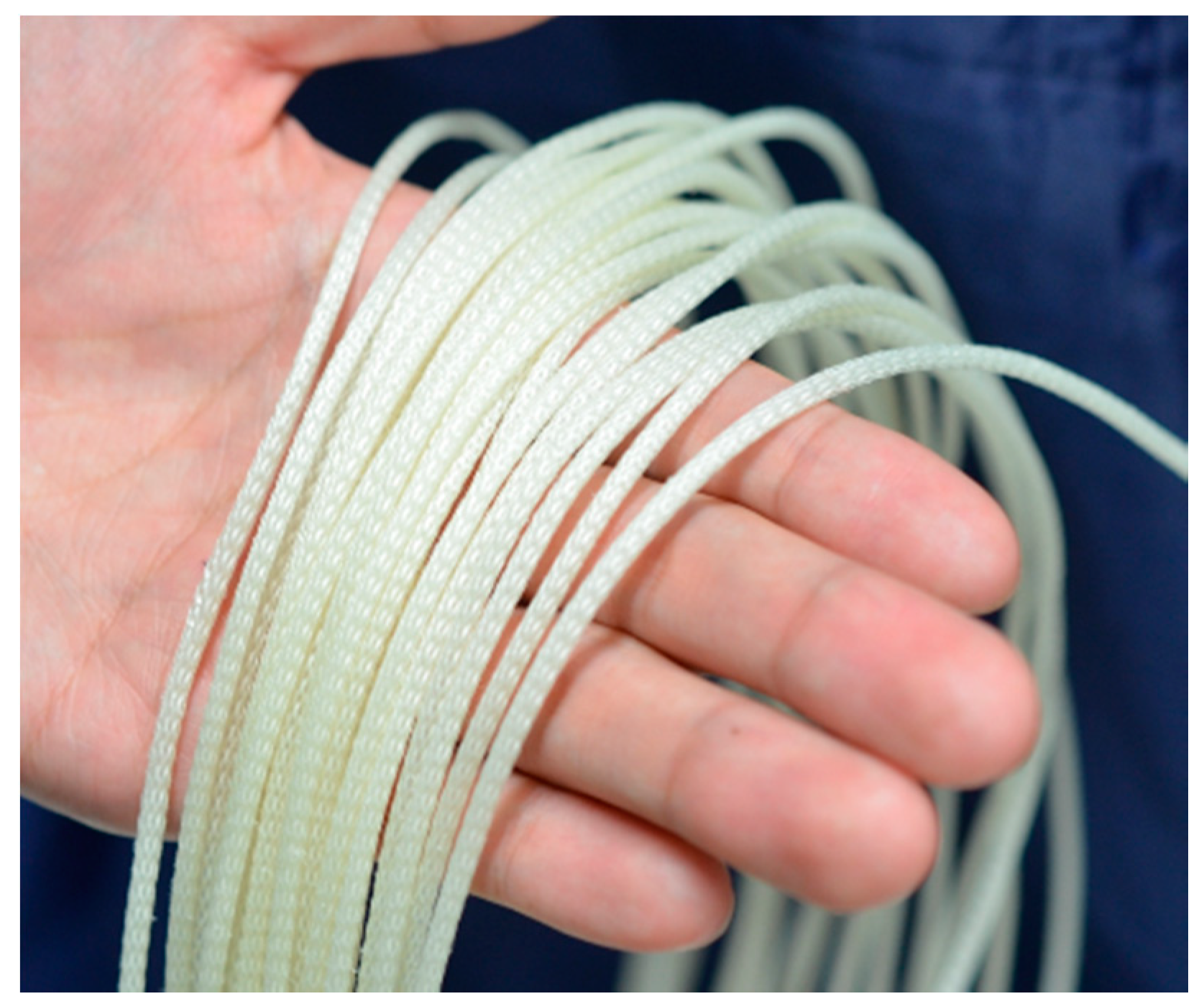
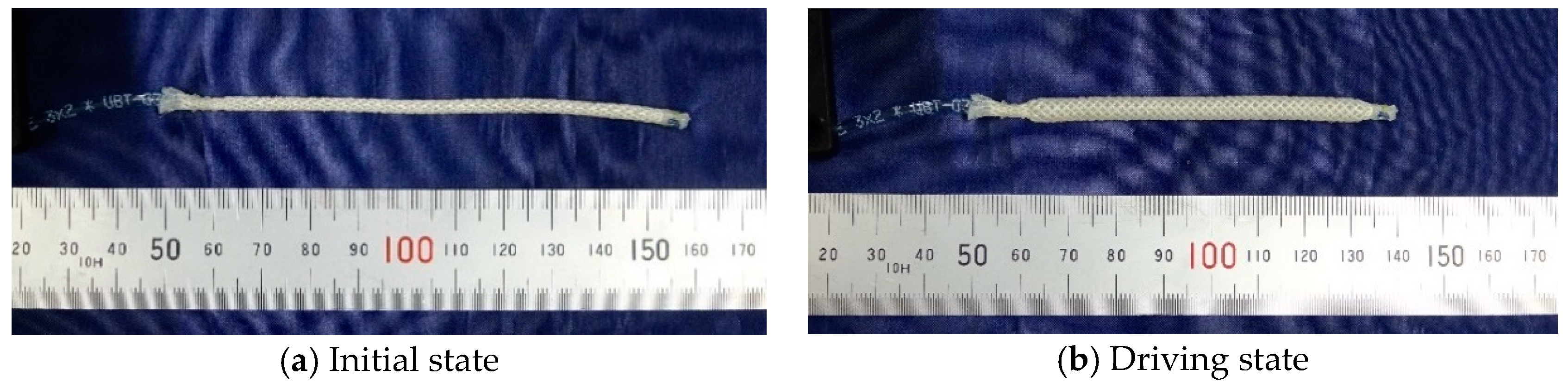
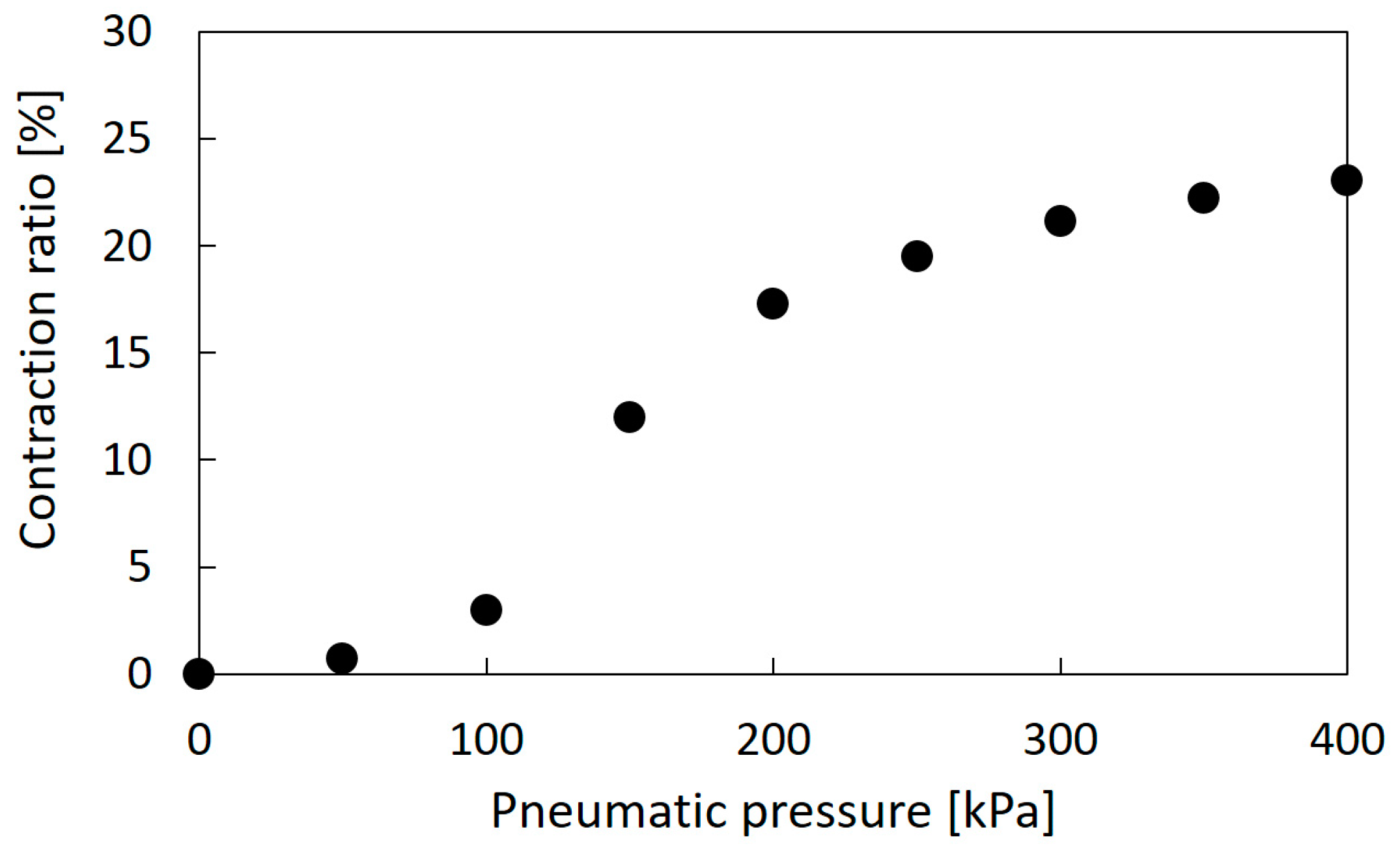
The thin McKibben artificial muscles were used as the actuators of the soft robot arm. This artificial muscle is 2.0 mm in diameter in its initial state and quite flexible, as shown in Figure 1; thus, it can be deformed easily to be arbitrarily shaped without buckling. Figure 2a,b shows the initial and driving states of the thin artificial muscle, and Figure 3 shows the correlation between the pneumatic pressure and the contraction ratio in the axial direction. The maximum contraction ratio is approximately 23% at a pneumatic pressure of 400 kPa.
2.2. Soft Robot Arm Structure
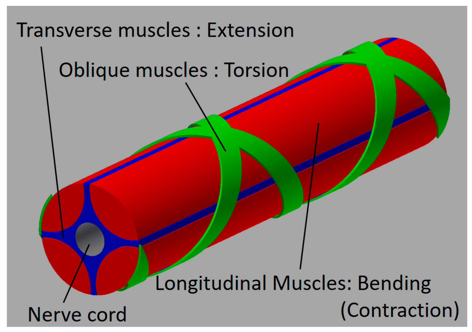
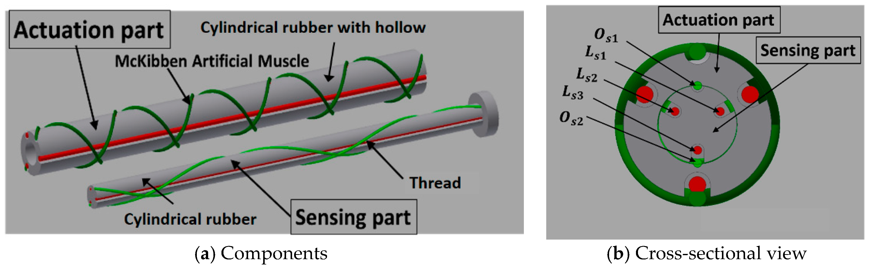
Although an actual octopus arm has a complicated structure, a simplified configuration of an octopus arm can be illustrated, as shown in Figure 4. It is primarily composed of the nerve cord and the muscles. The muscles are roughly divided into the longitudinal muscles (LMs), the oblique muscles (OMs), and the transverse muscles (TMs), arranged around the nerve code (NC) [2]. By driving the muscles independently or in combination, it is possible to perform contractions, extensions, bending and torsional motions. The LMs contribute mainly to the bending motion. The difference in lengths in the longitudinal direction is in part generated by driving some of the LMs, after which the octopus arm bends. When all LMs are driven with the same displacements, it contracts. The TMs contribute to the extension. By activating the TMs, the arm shrinks in the radial direction; then it extends in the longitudinal direction. The OMs are arranged spirally in clockwise and counterclockwise directions, which generates a torsional motion. Previously, we developed the soft robot arm with artificial muscles corresponding to the TMs, the LMs, and the OMs, and its motion was demonstrated [25]. In this report, focusing on the master-slave feedback control, a simplified version of the robot arm, with artificial muscles mimicking the LMs and the OMs (which mainly contribute to the bending and torsional motions), was fabricated to have a sensing part. Then, the master-slave feedback control system was established. Figure 5a shows the components of the soft robot arm. The robot arm consists mainly of two parts, the actuation part and the sensing part. The actuation part is configured with artificial muscles and a cylindrical rubber with a hollow, while the sensing part is configured with threads and a cylindrical rubber without a hollow. The sensing part is inserted into the center hollow of the actuation part, as shown in Figure 5b describing the cross-sectional view of the soft robot arm. Note that the red and green colors in Figure 5 are distinguished by arrangement directions: the longitudinal direction (red) or the oblique direction (green). The actuation part has artificial muscles, and the sensing part has threads. The mechanism of the sensing part is described in detail in Section 3.
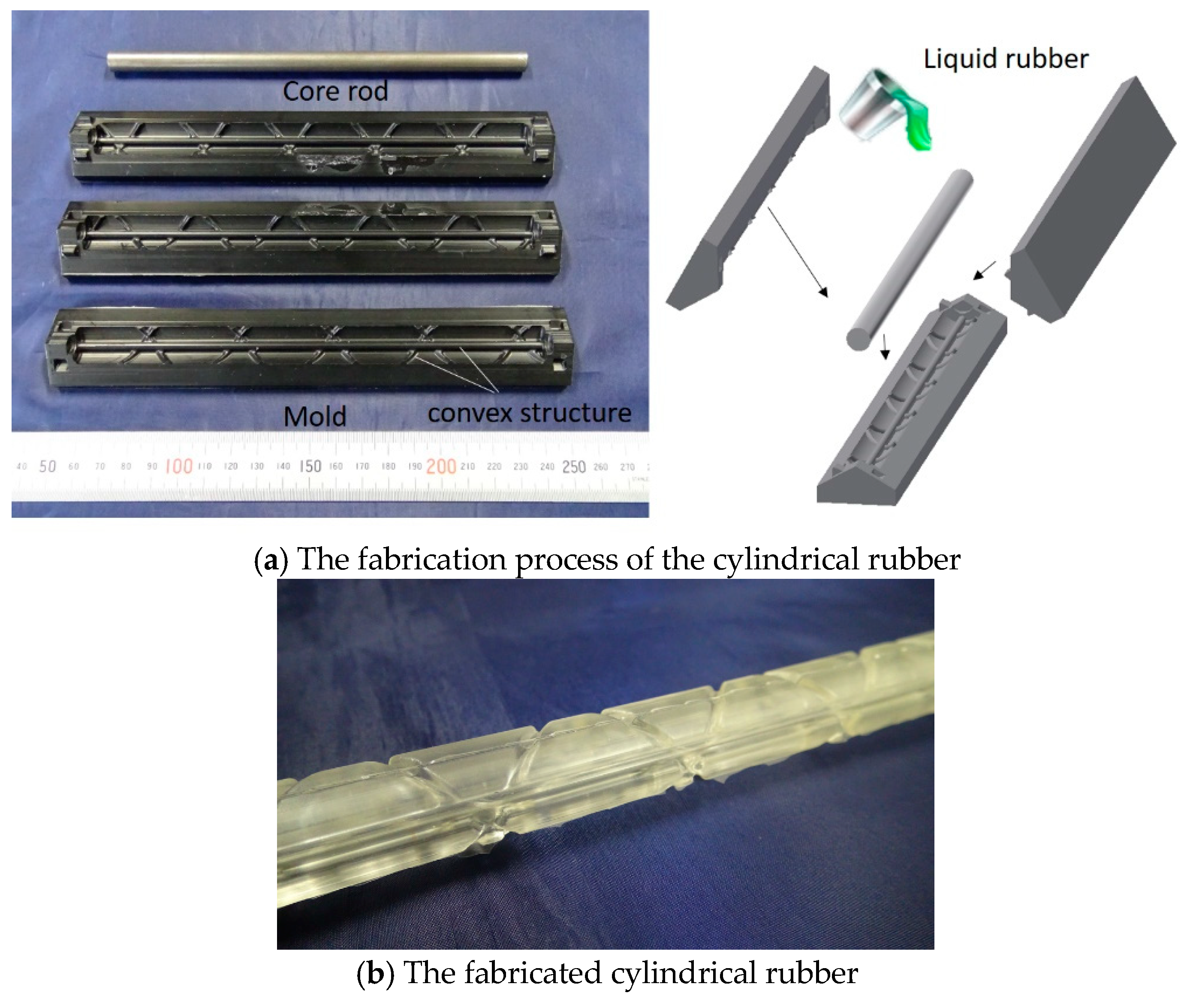
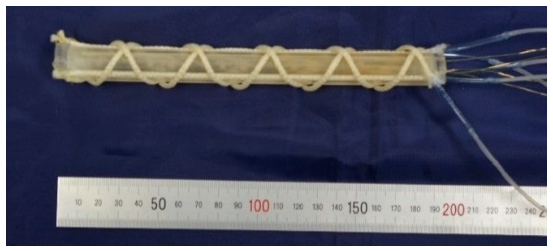
In the actuation part, three artificial muscles are arranged in the longitudinal direction, and two artificial muscles are arranged in the oblique direction. The bending operation is performed by driving the muscles in the longitudinal direction, while the torsional operation is performed by driving the muscles in the oblique direction. The hollow cylindrical rubber was made of silicone rubber (KE-1603, Hardness A 28; Shinetsu Silicone Co., Ltd.) and was fabricated through the molding process, as shown in Figure 6a. Three hard resin molds and a metal core rod were used. The curved inner surface of the molds has convex structures in the longitudinal and oblique directions. The molds were fabricated with a milling machine. The metal core rod was put on the center for making the hollow, and three molds were combined with pouring liquid-state rubber. Then, the liquid-state rubber, which is the RTV (Room Temperature Vulcanizing) type, entered the elastic rubber state after 24 h. Figure 6b shows the fabricated cylindrical rubber; concave channels were realized on the surface. The actuation part is accomplished by attaching the artificial muscles in the channels. Figure 7 shows the fabricated soft robot arm. The outer diameter and length of the actuation part are 17 mm and 180 mm, respectively. The spiral angle in the clockwise and counterclockwise directions of the oblique artificial muscles is 43.4°.
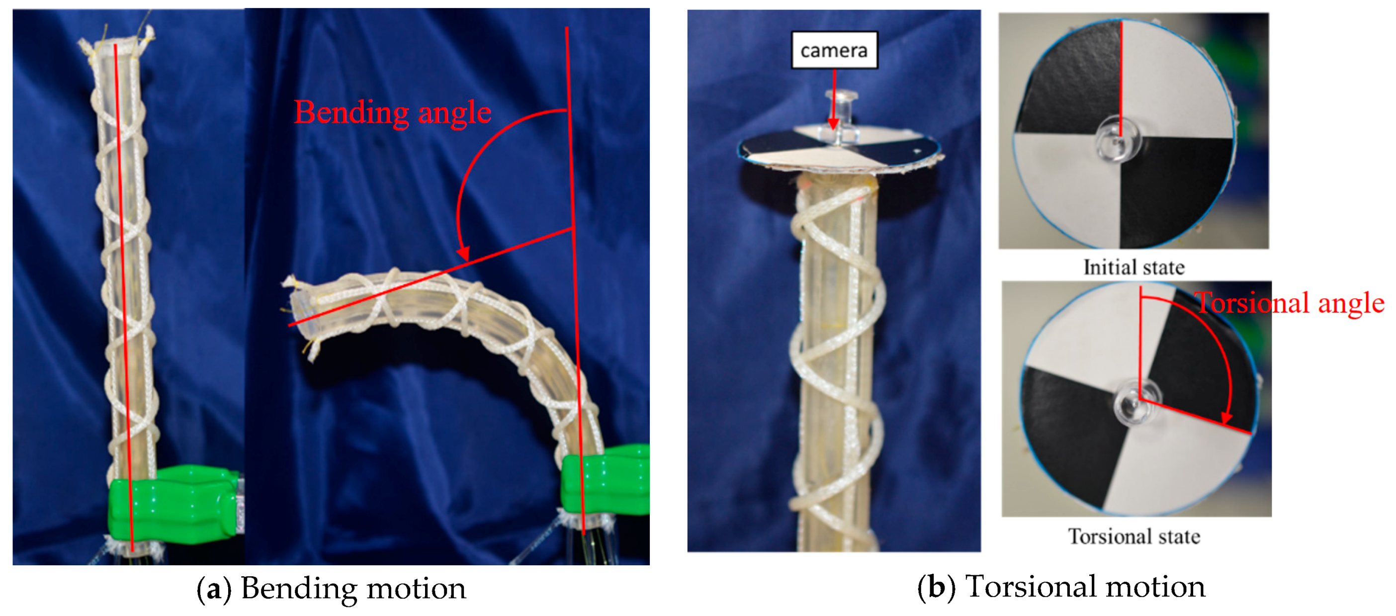
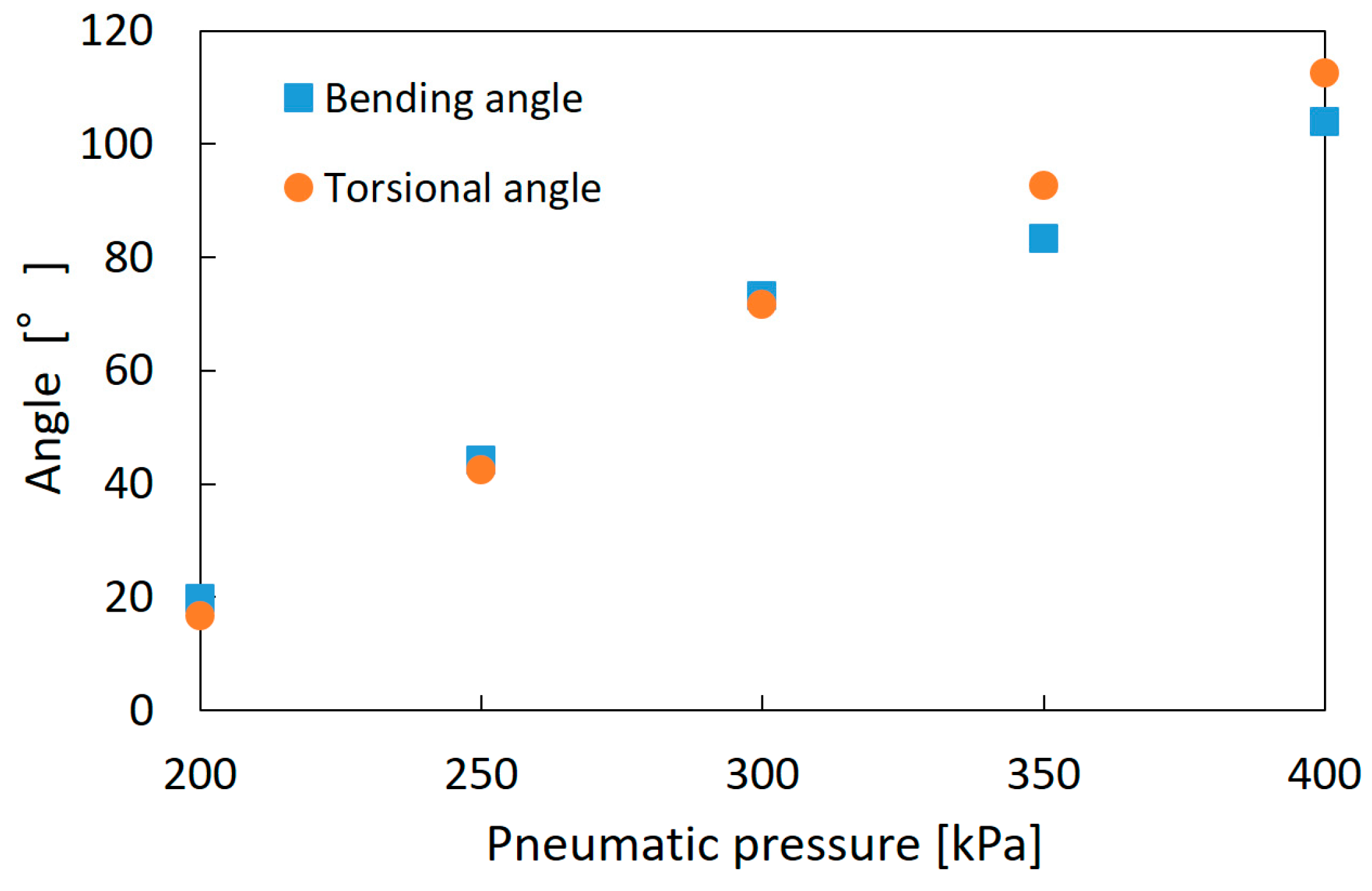
Figure 8a,b shows the bending and torsional motions of the soft robot arm. As the fundamental characteristics, the bending angle and torsional angle were measured by applying pneumatic pressure to one artificial muscle up to 400 kPa for each 50 kPa. The bending angle was defined as shown in Figure 8a, and the torsional motion was measured by attaching a black-white scale plate as shown in Figure 8b [25]. Figure 9 shows the results. The maximum bending angle is 104°, and the maximum torsional angle is 112°; below 200 kPa, the arm deformation was not observed because of the mechanical rigidity of the arm structure.
3. Master-Slave Control of the Soft Robot Arm
3.1. Configuration of the Sensing Part
To control the soft robot arm, which is a slave machine, the master-slave control system was established. The master-slave control is a remote-control method in which the motion of the master machine is given as the target motion of the slave machine instead of the numerical target value; thus, the slave machine traces the master machine motion. This control is suitable for the soft robot arm because the soft robot arm is expected to be applied in the medical, welfare, and agricultural fields. In these fields, there are many occasions that an operator’s sense and intent become more important than the numerical position and posture.
To estimate the soft robot arm motion, the sensing part was embedded into the actuation part, as illustrated in Figure 5. This part is configured with five threads around the cylindrical rubber made of the same silicone material as the hollow cylindrical rubber of the actuation part. To arrange the threads, the cylindrical rubber has concave channels on its surface. It was fabricated by a molding process with the molds having convex structures. The process is the same as the hollow cylindrical rubber of the actuation part, apart from the mold size and the absence of a rod because of there being no hollow in the cylindrical rubber of the sensing part, as shown in Figure 5a. The outer diameter and the length of the sensing part are 9 mm and 180 mm, respectively. Three threads are arranged into the longitudinal direction and correspond to the bending motion, and two threads are arranged spirally to measure the torsional motion. The spiral angle is 11.3°. This angle differs from that of the oblique artificial muscles. In cases of the same angle, namely 43.4°, the threads cannot slide following the torsional motion correctly, due to the friction between the threads and the cylindrical rubber.
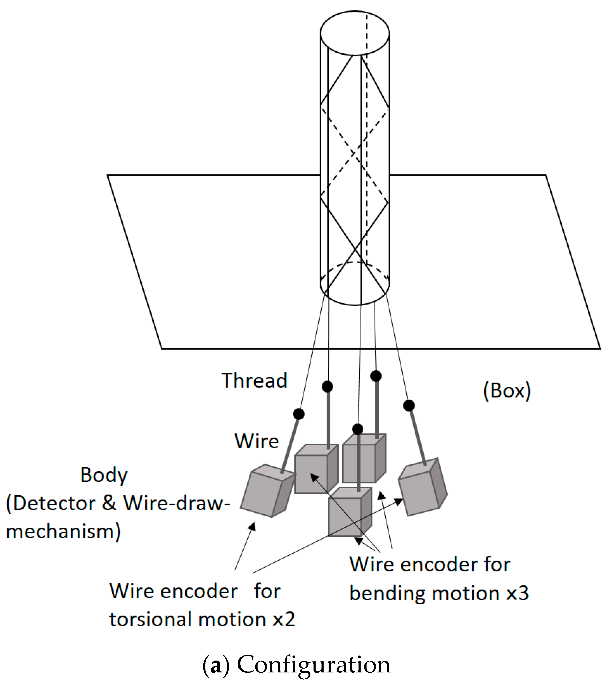
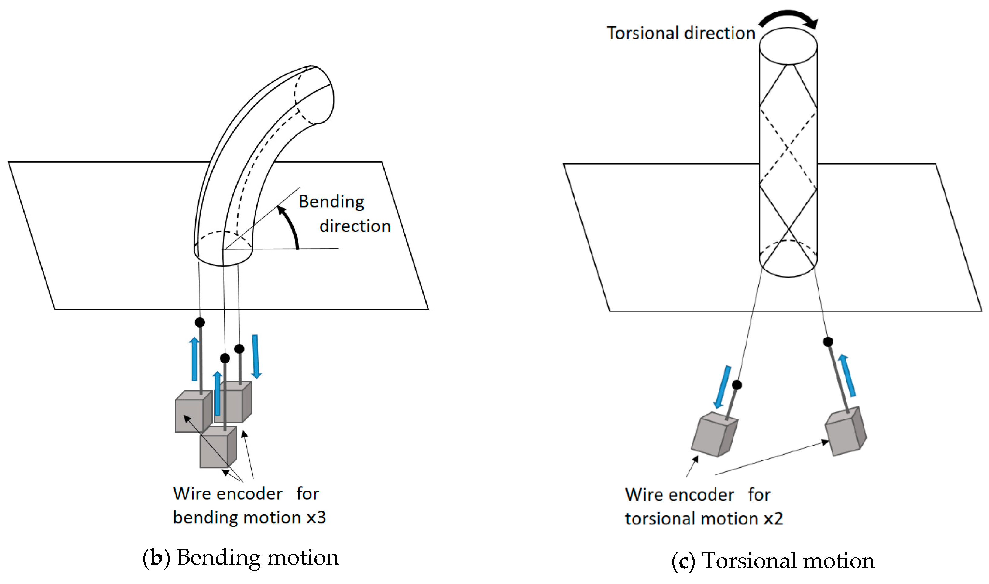
Figure 10 shows the sensing principle of the robot arm motion. In this figure, the actuation part is ignored, and the sensing part is depicted. Figure 10a illustrates the configuration. One end of each thread is connected to a wire of a wire encoder (DS-025; MUTOH Engineering Co., Ltd.), and the other end is fixed on the tip of the cylindrical rubber. The wire encoders are put in a box. The wire encoder consists of the wire and an encoder body consisting of a detector and a wire-draw-mechanism. The detector measures the displacement of the wire. The wire-draw-mechanism draws the wire into the encoder body; therefore, the wire is not loosened; however, this force is quite weak and does not interfere with the motion of the soft robot arm. When the robot arm bends or twists, the wire is pulled by the thread or drawn into the encoder body. To explain the basic sensing principle, Figure 10b,c focuses on the bending motion and the torsional motion, respectively. When the soft robot arm bends, as shown in Figure 10b, the wires connecting to the threads outside of the curved shape are pulled by the threads, and the wire connecting to the thread inside of the curved shape is drawn into the encoder body by the wire-draw-mechanism. When the torsional motion is realized, for example, it twists into the clockwise direction, as shown in Figure 10c, and the wire connecting to the thread arranged in the clockwise direction is pulled by the thread, while the wire connecting to the thread arranged in the counterclockwise direction is drawn by the wire-draw-mechanism. Thus, the sensing part measures the motion of the robot arm.
Because the sensing part consists of flexible threads and rubber material, it can be measured without impairing flexibility.
3.2. Master-Slave Control
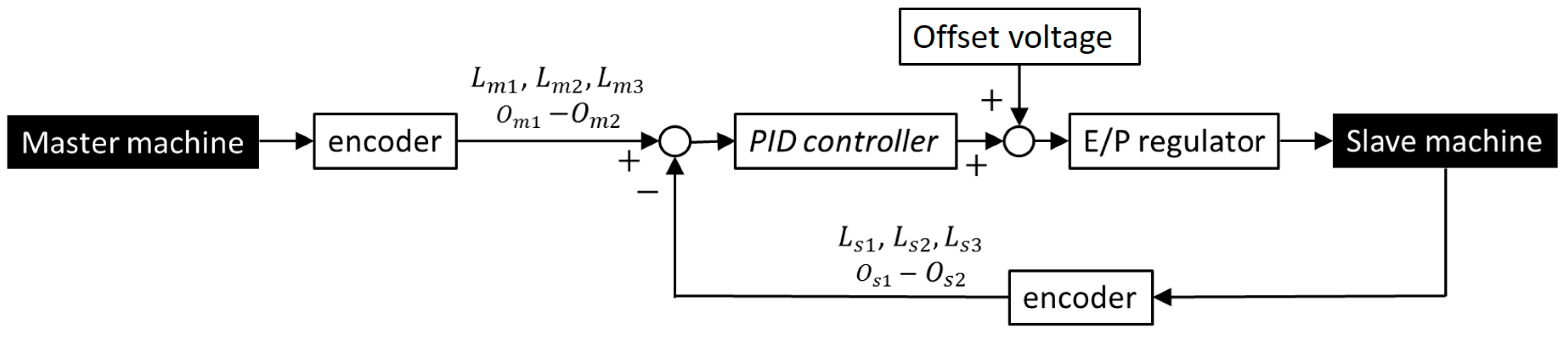
The master machine that is deformed by the operator has the same structure as the slave machine without the artificial muscles. The thread arrangement of the master and slave machines is the same, and each thread corresponds to each artificial muscle in the slave machine. Therefore, the feedback system can be realized through a comparison with the encoder values of the master machine and the slave machine without analytical models. A block diagram during the feedback control is shown in Figure 11. , , , and (i = 1,2,3, j = 1,2) are displacements of threads measured by the encoders that correspond to the longitudinal direction of the master machine, the oblique direction of the master machine, the longitudinal direction of the slave machine, and the oblique direction of the slave machine (see Figure 5b), respectively. The PID (Proportional-Integral-Derivative) controller is used to calculate the electrical voltage, which is the input signal to the E/P (Electro-Pneumatic) regulator. In addition, the offset electrical voltage is added to realize an offset pressure of 200 kPa for each artificial muscle. Through the offset pressure, the antagonistic motion of the artificial muscles can be achieved smoothly, and in addition this offset pressure reduces the influence of the dead pressure zone mentioned in Section 2 (Figure 9).
The bending motion can be controlled by directly comparing with . Meanwhile, for the torsional motion, the difference between and is used as the target value, and the difference between and is used as the feedback value. This is because it was found, experimentally, that depending on the bending motion the encoders’ value for detecting the torsional motion changed, even in the constant torsional state. The reason for this is that the threads in the oblique direction are wound with a small spiral angle to reduce the influence of the friction; however, due to this small angle the threads are influenced by the bending motion. This additional encoder value from the bending motion is generated on both threads in the clockwise direction and the counterclockwise direction. Therefore, it can be canceled through the difference of two encoders.
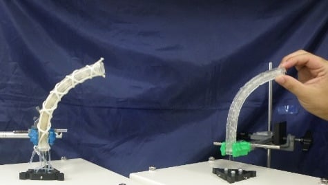
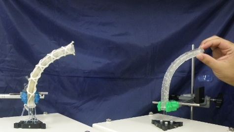
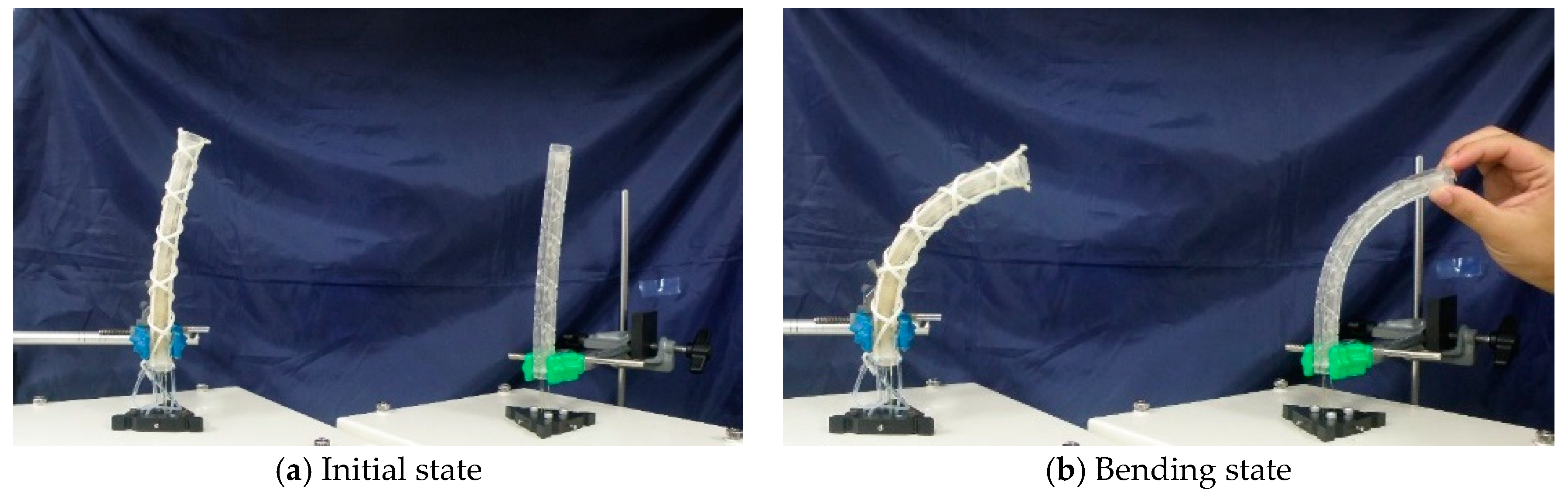
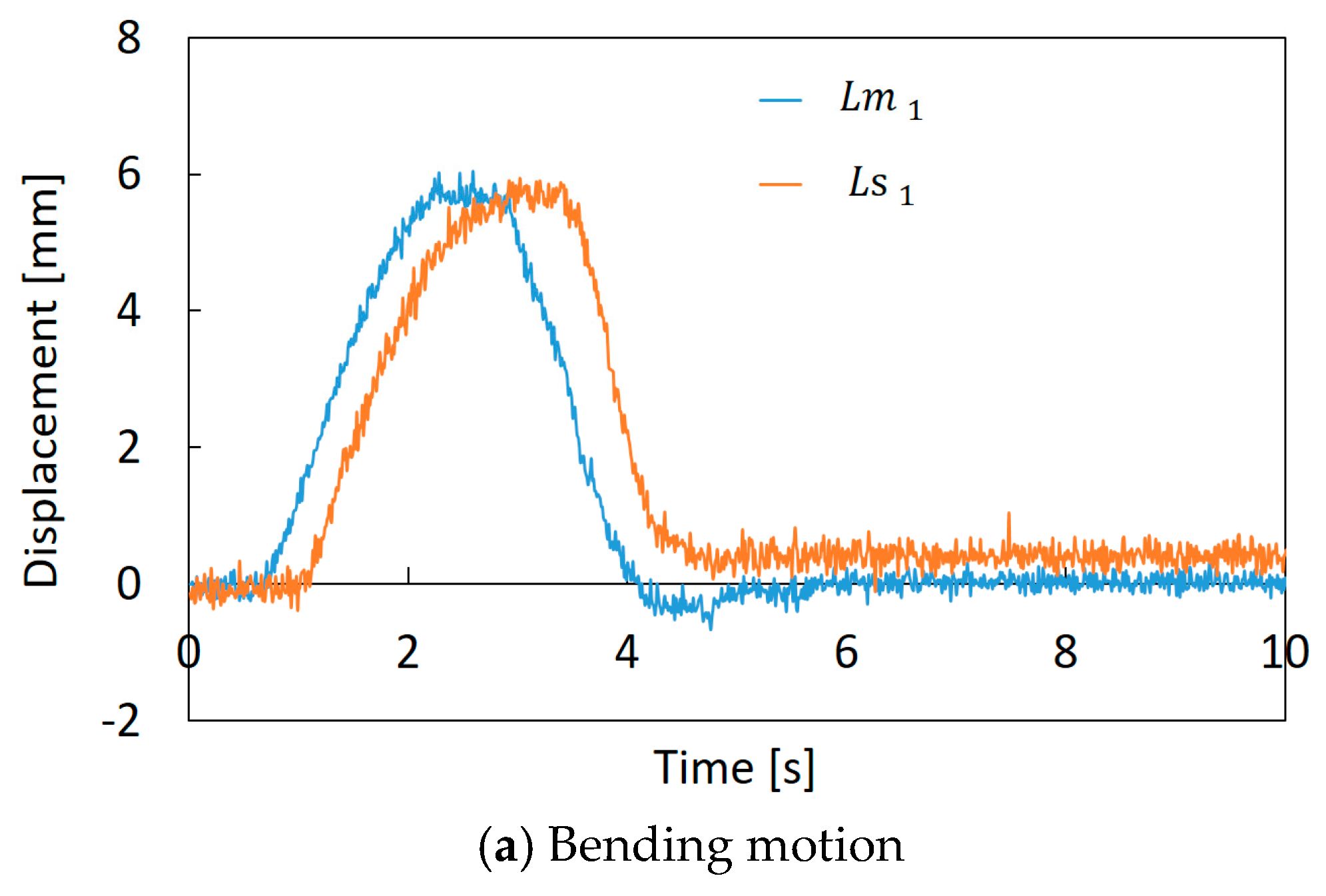
Figure 12a,b shows how the feedback control is performed. In the initial state, the robot arm bends slightly, as shown in Figure 12a, and this error comes from the manufacturing problem. This robot was made of flexible materials, and artificial muscles and threads were attached manually. Therefore, it is difficult to make the robot arm precisely. However, we consider that this shape error is small enough for the soft robot. The motion of the slave machine, following the arbitrary motion of the master machine, was confirmed, as shown in Figure 12b, which is an example of bending motion control. A comparison of the encoder values of the master machine and the slave machine in the bending operation is shown in Figure 13a. In this experiment, the operator bent the master machine in one direction, and and are represented in this graph as examples. Figure 13b represents the difference between and , and the difference between and , when the operator twisted the master machine into the clockwise and counterclockwise directions. We confirmed that the encoder values (displacements of the threads) of the slave machine followed those of the master machine. However, the time delay between the master and slave mechanisms is observed. This is mainly due to pneumatic flow characteristics that depend on pneumatic compressibility, the resistance of piping and the effective cross-section of the E/P regulator.
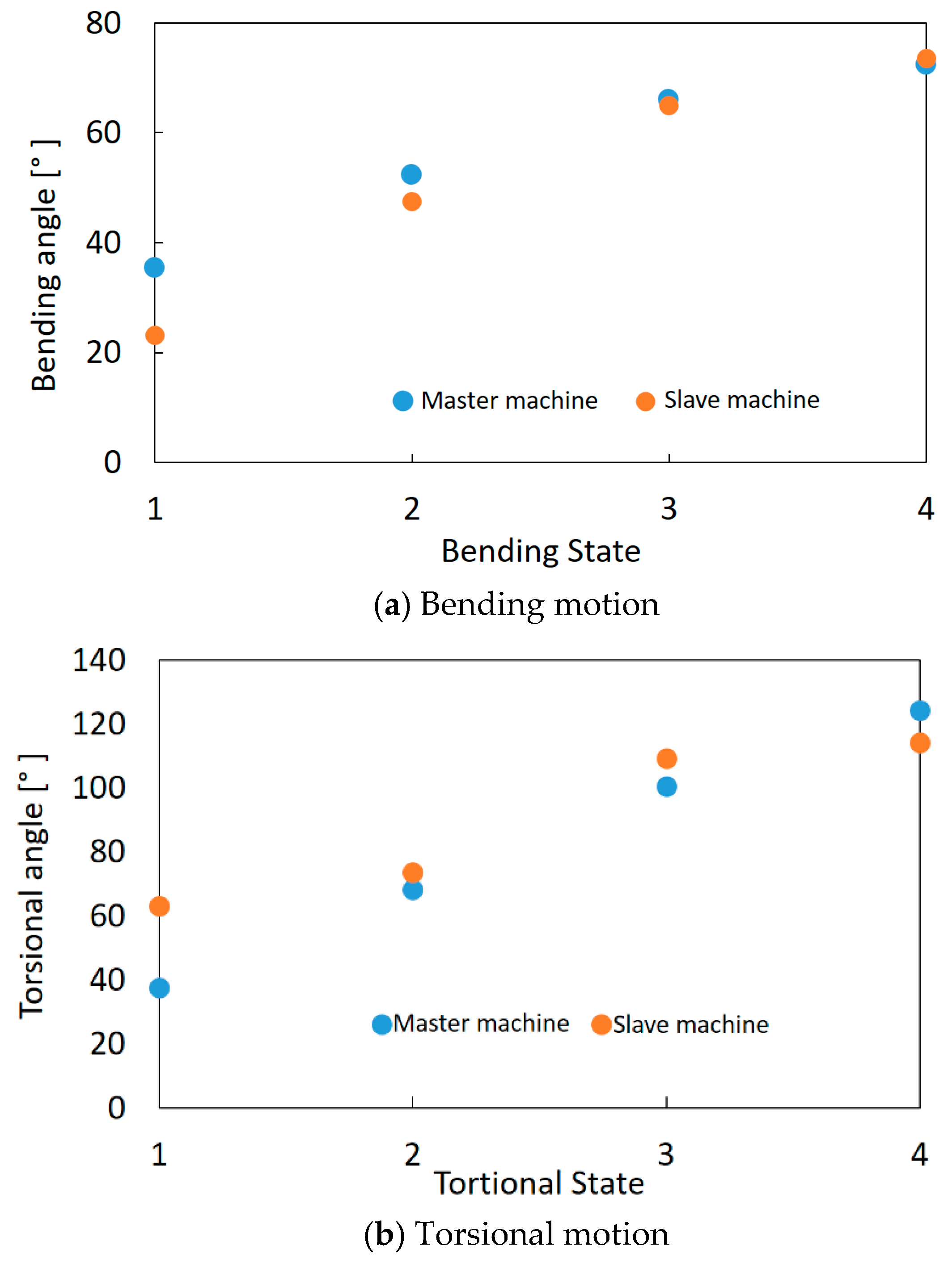
The bending and torsional angles of the master machine and the slave machine were compared. For the bending angle, a camera was set so that the bending motion of the machines is on one plane in the image. For the torsional angle, the images were acquired from the right above. From these images, the bending and torsional angles of the master machine and the slave machine were measured based on the definition as shown in Figure 8 through image analysis software (WinROOF, Mitani Corp.). Figure 14a,b shows the results of the bending motion and the torsional motion, respectively. In the experiments, four bending states and torsional states with different angles were compared. It is found that the bending and torsional angles of the master and slave machines were similar. The maximum error is about 10° at the bending angle and about 25° at the torsional angle. The curvature and torsional amounts of the master machine, which are deformed manually by the operator, are not uniform; they differ in part. Contrary to this, the uniformness of the deformation of the slave machine is high through its whole body because it is driven by artificial muscles. Therefore, the errors occurred even when the feedback control was performed. However, generally soft manipulators are not required to realize a high accuracy control; these errors can be considered as being at the acceptable level for many applications.
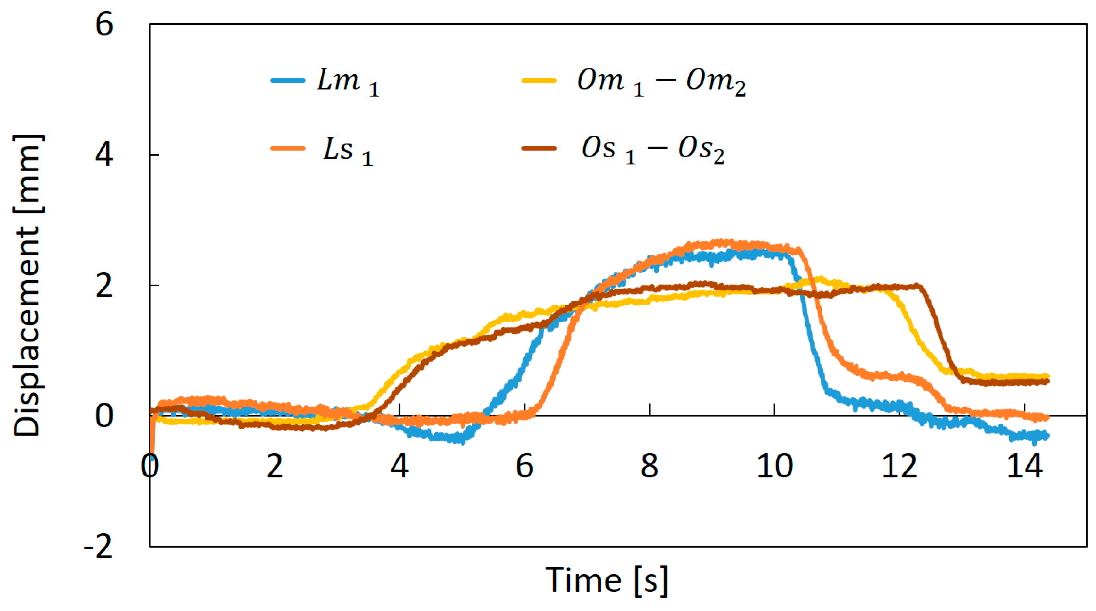
A composite motion control of the bending and torsion was performed. Figure 15 shows the results, in this graph, , , the difference between and , and the difference between and are represented as examples. In this experiment, the torsion was first performed in the vicinity of 4 s and the bending was applied in the vicinity of 6 s. After that, the bending was returned at around 10 s, and then the torsion was returned at 13 s. The encoder values of the slave machine followed those of the master machine correctly, and the motion of the slave machine followed the motion of the master machine actually. Such combining motions are difficult to evaluate at present through the image analysis, because for the complex motion the operator grasps the master machine, and the machine hides from the image partially through the operator’s hand. However, the results of Figure 13, Figure 14 and Figure 15 indicate that for the combination motion the soft robot arm moves following the master machine motion.
4. Conclusions
Robot arms made of soft materials are superior to conventional rigid robots in terms of safety and are expected to be useful in the agricultural, medical, and welfare fields. We developed the soft robot arm using thin McKibben artificial muscles. This robot arm can perform the bending motion and the torsional motion by mimicking the octopus arm structure. We consider that the control based on the operator’s intent is effective for the soft robot arm. Therefore, in this paper, the master-slave control system, using the wire encoders, was proposed and established. Both the master machine and the slave machine have no rigid material; they have only threads in their bodies for sensing.
The established system worked successfully; the motion of the slave machine followed the deformation of the master machine based on the operator’s intent.
This paper focused on the validity of the proposed method; therefore, the master and slave machines were designed to have the same size and configuration for simplification. For practical usage, a soft robot arm will be designed optimally for its application. Even in such a case, the control method proposed in this paper will be applied with ease because of its simplicity.
Author Contributions
Conceptualization, S.W.; Data curation, S.F. and H.H.; Funding acquisition, S.W.; Investigation, S.F. and H.H.; Methodology, S.W, S.F. and T.K.; Writing, S.F. and S.W.
Funding
This work was supported by a Grant for Promotion of Science and Technology in Okayama Prefecture from the Ministry of Education, Culture, Sports, Science and Technology, Japan for Atomic Energy Facilities, and a Grant-in-Aid for Scientific Research (c) (No. 17K06121) from Japan Society for the Promotion of Science in part.
Conflicts of Interest
The thin artificial muscle was developed by S-muscle Co., Ltd. and manufactured by Ikeda-Seityu Co., Ltd. S.W. is one of the founders of S-muscle Co., Ltd.
References
- Suzumori, K.; Ikuta, S.; Tanaka, H. Development of Flexible Microactuator and Its Applications to Robotic Mechanisms. In Proceedings of the International Conference on Robotics and Automation, Sacramento, CA, USA, 9–11 April 1991. [Google Scholar]
- Laschi, C.; Cianchetti, M.; Mazzolai, B.; Margheri, L.; Folladora, M.; Dario, P. Soft Robot Arm Inspired by the Octopus. Adv. Rob. 2012, 26, 709–727. [Google Scholar] [CrossRef]
- Jones, B.; McMahan, W.; Walker, I. Design and Analysis of a Novel Pneumatic Manipulator. Int. Fed. Acc. Mechatron. Syst. 2004, 37, 687–692. [Google Scholar] [CrossRef] [Green Version]
- Jain, R.K.; Patkar, U.S.; Majumdar, S. Micro gripper for micromanipulation using IPMCs (ionic polymer metal composites). J. Sci. Ind. Res. 2009, 68, 23–28. [Google Scholar]
- Hughes, J.; Culha, U.; Giardina, F.; Guenther, F.; Rosendo, A.; Iida, F. Soft Manipulators and Grippers: A Review. Front. Rob. AI 2016, 3, 69. [Google Scholar] [CrossRef]
- Schulte, H.F. The Characteristics of the McKibben Artificial Muscle. In The Application of External Power in Prosthetics and Orthotics; National Academy of Science-National Research Council: Washington, DC, USA, 1961; pp. 94–115. [Google Scholar]
- Chou, C.P.; Hannaford, B. Measurement and modeling of McKibben pneumatic artificial muscles. IEEE Trans. Rob. Autom. 1996, 12, 90–102. [Google Scholar] [CrossRef] [Green Version]
- Tondu, B. Robust and Accurate Closed-Loop Control of McKibben Artificial Muscle Contraction with a Linear Single Integral Action. Actuators 2014, 3, 142–161. [Google Scholar] [CrossRef] [Green Version]
- Al-Ibadi, A.; Nefti-Meziani, S.; Davis, S. Efficient Structure-Based Models for the McKibben Contraction Pneumatic Muscle Actuator: The Full Description of the Behaviour of the Contraction PMA. Actuators 2017, 6, 32. [Google Scholar] [CrossRef]
- Kothera, C.S.; Jangid, M.; Sirohi, J.; Wereley, N.M. Experimental Characterization and Static Modeling of McKibben Actuators. J. Mech. Des. 2009, 131, 9. [Google Scholar] [CrossRef]
- Felt, W.; Chin, K.Y.; Remy, C.D. Smart Braid Feedback for the Closed-Loop Control of Soft Robotic Systems. Soft Rob. 2017, 4, 261–273. [Google Scholar] [CrossRef] [PubMed]
- Wakimoto, S.; Misumi, J.; Suzurmoi, K. New concept and fundamental experiments of a smart pneumatic artificial muscle with a conductive fiber. Sens. Actuators A 2016, 250, 15–48. [Google Scholar] [CrossRef]
- Shin, H.; Saitoh, H.; Kawakami, T.; Yamanishi, S.; Ikemoto, S.; Hosoda, K. Development of an embedded sensor system for pneumatic artificial muscle proprioceptors. Artif. Life Rob. 2016, 21, 486–492. [Google Scholar] [CrossRef]
- Noritsugu, T.; Sasaki, D.; Kameda, M.; Fukunaga, A.; Takaiwa, M. Wearable Power Assist Device for Standing Up Motion Using Pneumatic Rubber Artificial Muscles. J. Rob. Mechatron. 2007, 19, 619–628. [Google Scholar] [CrossRef]
- Yeh, T.J.; Wu, M.J.; Lu, T.J.; Wu, F.K.; Hyang, C.R. Control of McKibben pneumatic muscles for a power-assist, lower-limb orthosis. Mechatronics 2010, 20, 686–697. [Google Scholar] [CrossRef]
- Kobayashi, H.; Aida, T.; Hashimoto, T. Muscle suit development and factory application. Int. J. Autom. Technol. 2009, 3, 709–715. [Google Scholar] [CrossRef]
- Kurumaya, S.; Suzumori, K.; Nabae, H.; Wakimoto, S. Musculoskeletal lower-limb robot driven by multifilament muscles. Robomech J. 2016, 3, 18. [Google Scholar] [CrossRef]
- Takuma, T.; Hosoda, K. Controlling the Walking Period of a Pneumatic Muscle Walker. Int. J. Rob. Res. 2006, 25, 9–861. [Google Scholar] [CrossRef]
- Faudzi, A.A.M.; Endo, G.; Kurumaya, S.; Suzumori, K. Long-Legged Hexapod Giacometti Robot Using Thin Soft McKibben Actuator. IEEE Rob. Autom. Lett. 2018, 3, 100–107. [Google Scholar] [CrossRef]
- Ohta, P.; Valle, L.; King, J.; Low, K.; Yi, J.; Atkeson, C.G.; Park, Y.L. Design of a Lightweight Soft Robotic Arm Using Pneumatic Artificial Muscles and Inflatable Sleeves. Soft Rob. 2018, 5, 2. [Google Scholar] [CrossRef] [PubMed]
- Al Abeach, L.A.T.; Nefti-Meziani, S.; Davis, S. Design of a Variable Stiffness Soft Dexterous Gripper. Soft Rob. 2017, 4, 3. [Google Scholar] [CrossRef] [PubMed]
- McMahan, W.; Chitrakaran, V.; Csencsite, M.; Dawson, C.; Walker, I.D.; Jones, B.A.; Pritts, M.; Dienno, D.; Grissom, M.; Rahn, C.D. Field Trials and Testing of the OctArm Continuum Manipulator. In Proceedings of the 2006 IEEE International Conference on Robotics and Automation, Orlando, FL, USA, 15–19 May 2006. [Google Scholar]
- Iwata, K.; Suzumori, K.; Wakimoto, S. Development of contraction and extension artificial muscles with different braid angles and their application to stiffness changeable bending rubber mechanism by their combination. J. Rob. Mechatron. 2011, 23, 582–588. [Google Scholar] [CrossRef]
- Kawamura, S.; Sudani, M.; Deng, M.; Noge, Y.; Wakimoto, S. Modeling and system integration for a thin pneumatic rubber 3-DOF actuator. Actuators 2019, 8, 32. [Google Scholar] [CrossRef]
- Doi, T.; Wakimoto, S.; Suzumori, K.; Mori, K. Proposal of Flexible robotic arm with thin McKibben actuators mimicking octopus arm structure. In Proceedings of the International Conference on Intelligent Robots and Systems, Daejeon, Korea, 9–14 October 2016. [Google Scholar]
- Aliff, M.; Dohta, S.; Akagi, T.; Li, H. Development of a Simple-Structured Pneumatic Robot Arm and its Control using Low-Cost Embedded Controller. Procedia Eng. 2012, 41, 134–142. [Google Scholar] [CrossRef]
- Trivedi, D.; Rahn, D.R.; Kier, W.M.; Walker, I.D. Soft robotics: Biological inspiration, state of the art, and future research. Appl. Bionics Biomech. 2008, 5, 99–117. [Google Scholar] [CrossRef]
- Sasaki, D.; Noritsugu, T.; Takaiwa, M. Wearable master-slave training device for lower limb constructed with pneumatic rubber artificial muscles. In Proceedings of the JFPS International Symposium on Fluid Power, Toyama, Japan, 15–18 September 2008. [Google Scholar]
Figure 1.
The thin McKibben artificial muscle.

Figure 2.
(a) Initial and (b) driving states of the thin artificial muscle.

Figure 3.
Relationship between the pneumatic pressure and the contraction ratio of the thin artificial muscle.
Figure 3.
Relationship between the pneumatic pressure and the contraction ratio of the thin artificial muscle.

Figure 4.
The structure of the octopus arm.

Figure 5.
Configuration of the soft robot arm: (a) Components. (b) Cross-sectional view in which the sensing part is inserted into the actuation part.
Figure 5.
Configuration of the soft robot arm: (a) Components. (b) Cross-sectional view in which the sensing part is inserted into the actuation part.

Figure 6.
(a) The fabrication process of the hollow cylindrical rubber with molds. (b) The fabricated hollow cylindrical rubber.
Figure 6.
(a) The fabrication process of the hollow cylindrical rubber with molds. (b) The fabricated hollow cylindrical rubber.

Figure 7.
The fabricated soft robot arm.

Figure 8.
The motion of the soft robot arm: (a) Bending motion. (b) Torsional motion.

Figure 9.
Fundamental motion characteristics of the soft robot arm.

Figure 10.
Sensing principle of the soft robot arm motion by wire encoders: (a) Configuration of the sensing system. (b) Sensing principle for the bending motion. (c) Sensing principle for the torsional motion.
Figure 10.
Sensing principle of the soft robot arm motion by wire encoders: (a) Configuration of the sensing system. (b) Sensing principle for the bending motion. (c) Sensing principle for the torsional motion.


Figure 11.
Block diagram of the master-slave control system.

Figure 12.
Performance of the master-slave control: (a) Initial state. (b) Bending state.

Figure 13.
Comparison of encoder values between the master machine and the slave machine: (a) Bending motion. (b)Torsional motion.
Figure 13.
Comparison of encoder values between the master machine and the slave machine: (a) Bending motion. (b)Torsional motion.


Figure 14.
Comparison of the motions between the master machine and the slave machine through image analysis: (a) Bending motion. (b)Torsional motion.
Figure 14.
Comparison of the motions between the master machine and the slave machine through image analysis: (a) Bending motion. (b)Torsional motion.

Figure 15.
Comparison of the encoder values between the master machine and the slave machine for the composite motion.
Figure 15.
Comparison of the encoder values between the master machine and the slave machine for the composite motion.

© 2019 by the authors. Licensee MDPI, Basel, Switzerland. This article is an open access article distributed under the terms and conditions of the Creative Commons Attribution (CC BY) license (http://creativecommons.org/licenses/by/4.0/).
Share and Cite
MDPI and ACS Style
Furukawa, S.; Wakimoto, S.; Kanda, T.; Hagihara, H. A Soft Master-Slave Robot Mimicking Octopus Arm Structure Using Thin Artificial Muscles and Wire Encoders. Actuators 2019, 8, 40. https://0-doi-org.brum.beds.ac.uk/10.3390/act8020040
AMA Style
Furukawa S, Wakimoto S, Kanda T, Hagihara H. A Soft Master-Slave Robot Mimicking Octopus Arm Structure Using Thin Artificial Muscles and Wire Encoders. Actuators. 2019; 8(2):40. https://0-doi-org.brum.beds.ac.uk/10.3390/act8020040
Chicago/Turabian StyleFurukawa, Shota, Shuichi Wakimoto, Takefumi Kanda, and Hiroki Hagihara. 2019. "A Soft Master-Slave Robot Mimicking Octopus Arm Structure Using Thin Artificial Muscles and Wire Encoders" Actuators 8, no. 2: 40. https://0-doi-org.brum.beds.ac.uk/10.3390/act8020040
Note that from the first issue of 2016, this journal uses article numbers instead of page numbers. See further details here.