A New Type of Rotary Magnetic Actuator System Using Electromagnetic Vibration and Wheel


Faculty of Engineering, Tohoku Gakuin University, Tagajo 985-8537, Japan
*
Author to whom correspondence should be addressed.
Actuators 2020, 9(3), 51; https://0-doi-org.brum.beds.ac.uk/10.3390/act9030051
Submission received: 19 June 2020
/
Revised: 3 July 2020
/
Accepted: 3 July 2020
/
Published: 6 July 2020
(This article belongs to the Section Actuators for Robotics)
Abstract
:In recent years, large structures, such as bridges, which are a type of social infrastructure, have been constructed with increasing traffic volume. For this reason, inspection and maintenance of social infrastructures, such as large bridges and tanks, is important. In the present paper, a magnetic wheel actuator system capable of movement using a new principle of locomotion was proposed and tested. The experimental results indicated a maximum pulling force of 1.6 N. By on-off control of the attractive force of the magnetic wheel, the actuator system was demonstrated to be able to move on a step having a height of 10 mm. Furthermore, the proposed actuator system could freely rotate in horizontal and vertical planes of over angles of 360°.
1. Introduction
In recent years, large structures, such as bridges, which are a form of social infrastructure, have been constructed with increasing traffic volume. On the other hand, for bridges built more than 50 years ago, collapse accidents can occur because of deterioration as a result of the secular variation. For this reason, inspection and maintenance of social infrastructure, including large bridges and tanks, is important. As adsorption methods for inspecting structures, the negative pressure of a pump [1], the wind force generated by a propeller [2], the force generated by a flexible rubber [3], a claw gripper [4,5,6], the adhesive force of a suction cup manufactured from a sponge [7], control of the attractive force of an electromagnet inserted in it [8], adhesive materials [9,10], and a permanent magnet and the magnetic wheel [11,12,13,14] have been proposed. The authors have proposed a new type of a magnetic-wheel-type actuator capable of movement with a new motion principle [15]. Especially, magnetic-wheel-type methods are an effective means for the movement of iron structures, such as cable-stayed bridges. However, it is not easy to move on a stepped surface and change the movement direction.
In the present study, a new type of a magnetic wheel actuator combining two iron disks—an electromagnet and a vibration component proposed by the authors [16,17,18]—was developed. Compared to the previous study [15], the magnetic wheels were replaced with permanent magnet types from electromagnet types. A prototype system was developed in which two actuators were connected, and on-off control of attractive force was possible. Compared to the previous study [15], it was designed so that an attractive force could be controlled on-off by replacing the permanent magnet type with an electromagnet type. In an experiment, a magnetic wheel actuator system with high-propulsion characteristics in which two actuators were connected by a flexible material was prototyped. By on-off controlling the attractive force of the magnetic wheel, the actuator system was demonstrated to be able to move on a step having a height of 10 mm. Furthermore, two shape memory alloy (SMA) coil springs and two friction pads were integrated into the actuator system in order to achieve rotational motion. By controlling the attractive force of the electromagnetic wheels of the actuator system, the system was shown to be able to rotate in-plane and vertical planes over angles of 360°. In the future, the actuator system will be equipped with multiple micro CCD (Charge Coupled Device) CCD cameras and will be applied to the visual inspection of a cable-stayed bridge with a main tower height of 200 m. Furthermore, the actuator system is applicable to the inspection of the iron structures, such as oil and gas tanks and power generation equipment.
2. Structure of Magnetic Wheel Actuator
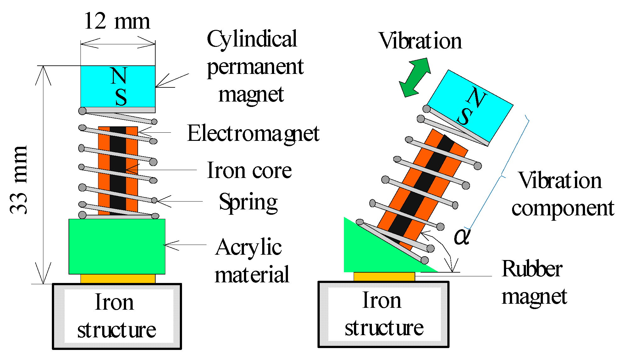
Figure 1 shows a diagram of the vibration component capable of movement on a magnetic material, as shown in a previous study [18]. The vibration component consisted of a permanent magnet, a translational spring, an electromagnet, a triangular acrylic frame, and a rubber permanent magnet attached to the bottom of the frame. The permanent magnet was cylindrical.
NdFeB (Neodymium) magnet NdFeB was magnetized in the axial direction. The permanent magnet was 12 mm in diameter and 5 mm in height. The translational spring was a stainless steel compression-coil-type, having an outer diameter of 11 mm, a free length of 18 mm, and a spring constant k of 2178 N/m. The electromagnet was inserted in the translational spring. The rubber permanent magnet magnetized in the thickness direction had a length of 9 mm, a width of 15 mm, a thickness of 2.8 mm, and an attractive force with respect to the iron material of 1.8 N. The vibration component was inclined at angle α from the horizontal plane. This vibration component realized a one-way movement by periodically changing the frictional force of the rubber magnet [18]. The vibration component had a height of 33 mm, a width of 15 mm, and a total mass of 13 g.
By extending the principle of locomotion, as shown in Figure 2, a new type of a magnetic wheel actuator was suggested. The magnetic wheel actuator consisted of two vibration components (labeled A and B), two E-shaped acrylic frames with four rods (labeled A, B, C, and D), an electromagnet, an acrylic shaft, and two iron disks. The two iron disks were rotated using the reaction force generated by the vibration component, as described below. Since the frictional force between the iron disk and the rubber magnet could be maintained constant, the frictional force during the rotational movement of the wheel actuator on the structure did not change. In Figure 2, the dimensions of the E-shaped frame in this figure corresponded to those of an iron disk of 40 mm in diameter. The thickness of this E-shaped frame was 3 mm.
3. Principle of Locomotion
The operation principle has already been described in the previous study [15]. This paper has described it in more detail. As shown in Figure 3, when the vibration component was placed on an iron structure, the component could vibrate due to the attractive force of the rubber magnet. The vibration component moved as a result of the vertical and horizontal components of the forces generated by the vibration component attached at an angle of 60° [18].
When the permanent magnet was displaced in the x-direction, as shown in Figure 3a, the frictional force acting on the support of the vibration component decreased. When the horizontal component force exceeded the friction force, the vibration component moved in the direction in which the vibration component was tilted. On the other hand, when the permanent magnet was displaced in the negative x-direction, as shown in Figure 3b, the frictional force increased. The vibration component could not slide backward. Thus, the magnetic actuator was propelled by the difference in frictional force between the forward and backward motions at the rubber magnet of support, as shown in a previous study [16,18].
As shown in Figure 4, the iron structure with a larger mass than the vibration component was prepared, and the component vibrated. Further, the iron structure was movable, and an object was set to prevent the movement of the vibration component. As shown in Figure 4a, when the permanent magnet was displaced in the x-direction, the vibration component could not move in the tilted direction due to the object. On the other hand, as shown in Figure 4b, when the permanent magnet was displaced in the negative x-direction, the iron structure received the force generated by the vibration component. When the horizontal component force exceeded the frictional force, the iron structure was pushed and slipped on the horizontal plane. The iron structure could be moved by the reaction force with respect to the action force for moving the vibration component.
This principle was applied to rotatable discs. When the vibration component was placed on a fixed iron disk, as shown in Figure 5a, the component moved in the direction in which the vibration component was tilted. When a supported state was imposed in order to prevent the motion of the vibration component, the iron disk rotated as a result of the reaction force of the component, as shown in Figure 5b. By inserting the vibration component into the E-shaped acrylic frame in such a way that the component was attracted to the iron disk, as shown in Figure 2c and Figure 5c, it was possible to rotate the disk while preventing the movement of the vibration component. As shown in Figure 2, when the two vibration components (A and B) were driven at the same frequency and the same amplitude, the wheel actuator could move linearly.
4. Consideration of Magnetic Wheel Actuator
When a magnetic wheel was placed on an iron structure, a magnetic path was formed between the electromagnet and the two iron disks, as shown in Figure 6. A lightweight and highly efficient electromagnetic wheel capable of on-off control of the input current had been experimentally designed. An acrylic axle having an outer diameter of 4.5 mm was inserted into the magnetic wheel. This axle was attached to rod C of the E-shaped frame. The electromagnet had a pipe-shaped core in which the inner diameter d1 of the iron core was 5 mm, and the outer diameter d2 was 7, 8, 9, or 10 mm. In the electromagnet, a copper wire having an outer diameter of 0.18 mm was used as a winding. Considering the weight, the outer diameter of the coil was 15 mm, and the length was 20 mm. In addition, three types of iron discs having thicknesses of t = 1, 1.5, or 2 mm and an outer diameter of D = 40 mm were used.
The prototype magnetic wheel was set on the iron structure, and the attractive force when a current was applied to the electromagnet was measured using a force gauge. The attractive force of the magnetic wheel is shown in Table 1 for various thicknesses t and outer diameters d2 of the disk when the magnetomotive force was unified to 200 A. Considering the attractive force and total mass of the magnetic wheel, an iron disk of thickness t = 1.5 mm and an electromagnet having an outer diameter d2 = 9 mm, an inner diameter d1 = 5 mm, and N = 1100 turns were selected. For the outer diameter D of the magnetic wheel, the minimum outer diameter of 40 mm in which the vibration component could be installed was selected in consideration of the weight and attractive force. With the above design, the prototype magnetic wheel actuator had a height of 40 mm, a width of 92 mm, a length of 40 mm, and a total mass of 76 g.
An experimental test was conducted using the apparatus shown in Figure 7. In the experiment, an iron rail of 50 mm in width, 50 mm in thickness, and 500 mm in length was used as a target iron structure. The vibration component was driven at a resonance frequency of 97 Hz using a function signal generator and an amplifier. Table 2 shows the relationship between the tilt angle of the iron rail and the speed when powered by an input power of 0.13 W for each vibration component. The attractive force was changed by changing the DC (Direct Current) DC input current into the electromagnet of the magnetic wheel using a power supply. The tilt angle was varied from -90° (straight downward) to 90° (straight upward). As the input current to the electromagnet increased, the speed of the wheel actuator also increased.
Figure 8 shows the relationship between the load mass and the vertical upward speed for the input power of 0.37 W for each vibration component. Here, the DC input current into the electromagnet of the magnetic wheel was changed to 0.12 A, 0.16 A, and 0.2 A. As shown in the figure, the maximum pulling force of this magnetic wheel actuator was 0.8 N.
5. Movement Characteristics of Actuator System
In order to improve the propulsion characteristics and realize step movement, an actuator system in which two magnetic wheel actuators (A and B) were connected by two connection materials was developed, as shown in Figure 9. Silicone rubber was selected as the connection material, and rods A and C of the E-shaped acrylic frame were connected to each other. The silicone rubber connector had a length of 55 mm, a width of 7 mm, and a thickness of 3 mm.
Furthermore, for the purpose of movement on the step surface, rods B and D of the E-shaped acrylic frame were changed to a slope shape. The actuator system had two friction pads and two shape memory alloy (SMA) coil springs. Natural rubber material having a length of 7 mm, a width of 7 mm, and a thickness of 2 mm was used as the friction pad. The actuator system had a height of 40 mm, a width of 92 mm, a total length of 90 mm, and a total mass of 158 g. Figure 10 is a photograph of the prototype actuator system.
Figure 11 shows by solid lines the relationship between the load mass and the vertical upward speed for an input power of 0.37 W for each vibration component. The DC current passing through the electromagnet of the magnetic wheel was 0.2 A. The broken line in the figure indicated the result for the case of a single-wheel actuator, as shown in Figure 2. The actuator system could move vertically at a speed of 18.6 mm/s with a load mass of 160 g. The filled black circles indicate the results when two actuators were connected by an acrylic material with the same dimensions as the silicone rubber. By using the silicone rubber to reduce the interference between the vibration component, the propulsion characteristic of the actuator system could be doubled compared to that of the single-wheel actuator. Furthermore, when the same electric power was applied to the electromagnet of the vibration component, the result of the previous study [15] having a permanent magnet type magnetic wheel was shown. The propulsion characteristics of the actuator system were considerably improved compared with those of the single type model.
Furthermore, the tilt angles β1 and β2 of the iron rail were varied, as shown in Figure 12. In this figure, β1 indicates movement from a horizontal plane, and β2 indicates movement from the slide-on-ceiling movement.
Figure 13 shows the relationship between the tilt angle β1 and angle β2 of the iron rail from the horizontal plane and the speed of the actuator system. In this figure, the solid line and dashed line indicate the variation in tilt angles β1 and β2, when powered the input power of 0.13 W for each vibration component. The DC current passing through the magnetic wheel was 0.2 A. In this actuator system, both slide-on-ceiling and wall-climbing motions were possible.
6. Movement Characteristics on the Step of the Actuator System
If there was a step on the surface of the iron structure, the single-wheel actuator shown in Figure 2 could not move. The actuator system could move on the step by on-off control of the DC current of the electromagnet in the magnetic wheel. The driving procedure for movement on the step was as follows.
(1) As shown in Figure 14a, when the actuator system contacted the step, the DC current flowing to the electromagnet of magnetic wheel A in actuator A was set to zero.
(2) As shown in Figure 14b, actuator A was pushed up onto the step using the propulsive force of actuator B.
(3) A DC current was applied to the electromagnet of magnetic wheel A to form a magnetic path, and the actuator system moved. As shown in Figure 14c, when actuator B contacted the step, the DC current flowing to the electromagnet of wheel B was set to zero.
(4) Actuator B was pulled up onto the step using the propulsive force of actuator A.
(5) When the actuator system descended the step, on-off current control of the electromagnet was not required. The actuator system by driving actuators A and B could move.
In the measurement, the DC current applied to the electromagnet for the wheel was 0.2 A, and the input power to the electromagnet of the vibration component was set to 0.37 W. The actuator system was placed horizontally, and the length L of the step was set to 100 mm. Then, the movement time and the average speed until transition from Figure 14a–d are shown in Table 3 for various step heights h.
The various step heights ‘h’ are shown in Table 3 and Figure 14a–d. The actuator system could move on a step surface, having a maximum step height of 10 mm. According to the above driving procedure, setting the height of the step to 10 mm and the measurement distance to 200 mm, the results for the case of a convex step are shown in Table 4 for various lengths, as shown in Figure 14b.
7. Turning Properties of the Actuator System
In this actuator system, the movement was limited to one direction by the movement principle of the system. As mentioned above, two SMA coil springs and two friction pads were incorporated into the magnetic wheel actuator system, and the ability of the system to execute turning operations was examined. Figure 15 shows an overview of an actuator system capable of turning. The SMA coil spring and a friction pad were attached to rods A and B, respectively, of the E-shaped acrylic frame for actuator B via a conductor. The length of the SMA coil spring without a DC input current was 40 mm. The method of rotating the actuator system was as follows.
(1) The DC currents flowing through the electromagnets of the wheels for actuators A and B were set to off and on, respectively. Even if the actuator system was formed by the permanent magnet type shown in the previous study [15], the turning operation could not be performed.
(2) A DC current was applied to the SMA X coil spring, and the coil spring contracted. Rod A of the E-shaped acrylic material for actuator B was bent. The iron disk and the friction pad X contacted each other, as shown in Figure 15a, and a fulcrum point was formed where the iron disk did not rotate.
(3) In this state, when the vibration component in Figure 15a was operated, a moment was applied at the fulcrum.
(4) The actuator system could turn in the clockwise direction, as shown in Figure 16.
Since two SMA coil springs and two friction pads were used in this setup, the actuator system could be turned clockwise or counterclockwise, as shown in Figure 15b, depending on the degree to which the SMA coil spring was contracted.
The DC current applied to the electromagnet for the wheel of actuator B and the SMA coil spring was 0.2 A, and the input power to the electromagnet of the vibration component was set to 0.37 W. Table 5 shows the clockwise and counterclockwise turning speeds when the actuator system was set on horizontal and vertical planes. This actuator system could freely change the direction of movement over 360°.
8. Conclusions
A magnetic wheel actuator system capable of movement using a new locomotion principle had been proposed and tested. Experimental results revealed that the proposed actuator system was able to pull a load mass of 160 g when the input power of the electromagnet of the vibration component was 0.37 W. By joint operation of single-wheel actuator and on-off control of the DC current into the wheel, the actuator system was demonstrated to be able to move on a step having a height of 10 mm. In addition, as a result of the attachment of a shape memory alloy spring and a friction pad, the actuator system was shown to be able to rotate in-plane and vertical planes over an angle of 360°. In the future, we plan to improve the propulsive characteristics of the vibration component, attach a CCD micro camera to an acrylic E-shaped frame, and perform a visual inspection of the iron structure.
Author Contributions
H.Y. initiated and supervised the development of the actuator and wrote the paper, I.K. and S.S. performed the development, design, assembly and integration of the prototype. All authors have read and agreed to the published version of the manuscript.
Funding
This research received no external funding.
Conflicts of Interest
The authors declare no conflict of interest.
References
- Subramanyam, A.; Mallikarjuna, Y.; Suneel, S.; Kumar, L.B. Design and Development of a Climbing Robot for Several Applications. Int. J. Adv. Comput. Technol. 2011, 3, 15–23. [Google Scholar]
- Shin, J.-U.; Kim, D.; Kim, J.-H.; Myung, H. Micro aerial vehicle type wall-climbing robot mechanism. In Proceedings of the IEEE RO-MAN International Symposium, Gyeongju, Korea, 26–29 August 2013; pp. 722–725. [Google Scholar]
- Yoshida, Y.; Ma, S. A Wall-Climbing Robot without any Active Suction Mechanisms. In Proceedings of the IEEE International Conference on Robotics and Biomimetics, Phuket Island, Thailand, 7–11 December 2011; pp. 2014–2019. [Google Scholar]
- Xu, F.; Wang, X.; Jiang, G. Design and Analysis of a Wall-Climbing Robot Based on a Mechanism Utilizing, Hook-Like Claws. Int. J. Adv. Robot. Syst. 2012, 9, 261. [Google Scholar] [CrossRef] [Green Version]
- Funatsu, M.; Kawasaki, Y.; Kawasaki, S.; Kikuchi, K. Development of cm-scale Wall Climbing Hexapod Robot with Claws. In Proceedings of the 3rd International Conference on Design Engineering and Science—ICDES, Pilsen, Czech Republic, 31 August–3 September 2014; pp. 101–106. [Google Scholar]
- Provancher, W.; Jensen-Segal, S.; Fehlberg, M. ROCR: An Energy-Efficient Dynamic Wall-Climbing Robot. IEEE Trans. Mechatron. 2011, 16, 897–906. [Google Scholar] [CrossRef]
- Fukuda, T.; Matsuura, H.; Arai, F.; Nishibori, K.; Sakauchi, H.; Yoshi, N. A Study on Wall Surface Mobile Robots. Trans. Jpn. Soc. Mech. Eng. 1992, 58, 286–293. [Google Scholar]
- Suzuki, M.; Hirose, S. Proposal of Swarm Type Wall Climbing Robot System Anchor Climber and Development of Adhering Mobile Units. Robot. Soc. Jpn. 2010, 28, 614–623. [Google Scholar] [CrossRef] [Green Version]
- Kute, C.; Murphy, M.; Menguc, Y.; Sitti, M. Adhesion Recovery and Passive Peeling in a Wall Climbing Robot using Adhesives. In Proceedings of the IEEE International Conference on Robotics and Automation, Anchorage, Alaska, 3–8 May 2010; pp. 2797–2802. [Google Scholar]
- Unver, O.; Sitti, M. Tankbot: A Miniature, Peeling Based Climber on Rough and Smooth Surfaces. In Proceedings of the IEEE International Conference on Robotics and Automation, Kobe, Japan, 12–17 May 2009; pp. 2282–2287. [Google Scholar]
- Khirade, N.; Sanghi, R.; Tidke, D. Magnetic Wall Climbing Devices—A Review. In Proceedings of the International Conference on Advances in Engineering & Technology, Singapore, 29–30 March 2014; pp. 55–59. [Google Scholar]
- Kim, J.H.; Park, S.M.; Kim, J.H.; Lee, J.Y. Design and Experimental Implementation of Easily Detachable Permanent Magnet Reluctance Wheel for Wall-Climbing Mobile Robot. J. Magn. 2010, 15, 128–131. [Google Scholar] [CrossRef] [Green Version]
- Fujji, N.; Nonako, S.; Hayashi, G. Design of magnet wheel integrated own drive. IEEE Trans. Magn. 1999, 35, 5. [Google Scholar] [CrossRef]
- Qin, W.; Bird, J.Z. Electrodynamic Wheel Magnetic Rolling Resistance. IEEE Trans. Magn. 2017, 53, 8. [Google Scholar] [CrossRef]
- Yaguchi, H.; Kimura, I.; Sakuma, S. A Novel Actuator System Combining Mechanical Vibration and Magnetic Wheels Capable of Rotational Motion Using Shape Memory Alloy Coils. Actuators 2019, 8, 4. [Google Scholar] [CrossRef] [Green Version]
- Yaguchi, H.; Sakuma, S. A Novel Magnetic Actuator Capable of Free Movement on a Magnetic Substance. IEEE Trans. Magn. 2015, 51, 11. [Google Scholar] [CrossRef]
- Yaguchi, H.; Sakuma, S. Characteristic Improvement of a Magnetic Actuator Capable of Movement on a Magnetic Substance. IEEE Trans. Magn. 2016, 52, 7. [Google Scholar] [CrossRef]
- Yaguchi, H.; Sakuma, S. Vibration Actuator Capable of Movement on Magnetic Substance Based on New Motion Principle. J. Vibroeng. 2017, 19, 1494–1508. [Google Scholar]
Figure 1.
Structure of the vibration component.

Figure 2.
Structure of the magnetic wheel actuator: (a) Plan view of the actuator, (b) Front view of the actuator, (c) E-shaped acrylic frame of the actuator, (d) Side view of the actuator.
Figure 2.
Structure of the magnetic wheel actuator: (a) Plan view of the actuator, (b) Front view of the actuator, (c) E-shaped acrylic frame of the actuator, (d) Side view of the actuator.

Figure 3.
Vibration component on an iron structure: (a) Sliding of the actuator, (b) Stop of the actuator.
Figure 3.
Vibration component on an iron structure: (a) Sliding of the actuator, (b) Stop of the actuator.

Figure 4.
Vibration component on an iron structure: (a) Stop of iron structure by the actuator, (b) Sliding of iron structure by the actuator.
Figure 4.
Vibration component on an iron structure: (a) Stop of iron structure by the actuator, (b) Sliding of iron structure by the actuator.

Figure 5.
Principle of locomotion: (a) Action by the actuator, (b) Reaction of the actuator, (c) Linear movement by reaction of the actuator.
Figure 5.
Principle of locomotion: (a) Action by the actuator, (b) Reaction of the actuator, (c) Linear movement by reaction of the actuator.

Figure 6.
Structure of the magnetic wheel.

Figure 7.
Experimental apparatus.

Figure 8.
Relationship between load mass and vertical upward speed.

Figure 9.
Structure of the magnetic wheel actuator system: (a) Plan view of the actuator system, (b) Front view of the actuator system, (c) Side view of the actuator system.
Figure 9.
Structure of the magnetic wheel actuator system: (a) Plan view of the actuator system, (b) Front view of the actuator system, (c) Side view of the actuator system.

Figure 10.
Photograph of the magnetic wheel actuator system: (a) Actuator system, (b) Iron rail and actuator system.
Figure 10.
Photograph of the magnetic wheel actuator system: (a) Actuator system, (b) Iron rail and actuator system.

Figure 11.
Relationship between load mass and vertical upward speed.

Figure 12.
Magnetic actuator system moving on the iron rail.

Figure 13.
Relationship between the tilt angle β of the iron rail and the movement speed.

Figure 14.
Magnetic actuator system capable of movement on a step: (a) Actuator A in contact with step, (b) Movement of step by the actuator system, (c) Actuator B in contact with step, (d) Movement of step by the actuator system.
Figure 14.
Magnetic actuator system capable of movement on a step: (a) Actuator A in contact with step, (b) Movement of step by the actuator system, (c) Actuator B in contact with step, (d) Movement of step by the actuator system.

Figure 15.
Principle of turning: (a) Plan view of Clockwise direction for the actuator system, (b) Front view of Clockwise direction for the actuator system, (c) Plan view of Counterclockwise direction for the actuator system, (d) Front view of Counterclockwise direction for the actuator system.
Figure 15.
Principle of turning: (a) Plan view of Clockwise direction for the actuator system, (b) Front view of Clockwise direction for the actuator system, (c) Plan view of Counterclockwise direction for the actuator system, (d) Front view of Counterclockwise direction for the actuator system.

Figure 16.
Turning in the clockwise direction.


Table 1.
The attractive force of the magnetic wheel.
| Outer Diameter d2 | Turn of Winding | Resistance | Attractive Force | ||
|---|---|---|---|---|---|
| t = 1 mm | t = 1.5 mm | t = 2 mm | |||
| 7 mm | 1520 | 35.0 Ω | 7.5 N | 9.0 N | 9.8 N |
| 8 mm | 1370 | 33.4 Ω | 8.6 N | 14.1 N | 14.7 N |
| 9 mm | 1100 | 28.4 Ω | 9.2 N | 15.2 N | 15.9 N |
| 10 mm | 850 | 22.6 Ω | 9.8 N | 13.9 N | 15.1 N |
Table 2.
Speed of wheel actuator by the tilt angle of rail.
| Input Current of Electromagnet | Attractive Force | Speed (Downward) | Speed (Horizontal) | Speed (Upward) |
|---|---|---|---|---|
| 0.12 A | 14.6 N | 37.6 mm/s | 36.5 mm/s | 13.4 mm/s |
| 0.16 A | 18.2 N | 39.6 mm/s | 39.0 mm/s | 14.8 mm/s |
| 0.2 A | 21.8 N | 41.7 mm/s | 41.0 mm/s | 16.8 mm/s |
Table 3.
Movement time and average speed (step).
| Height h of Step | Time | Average Speed |
|---|---|---|
| 0 mm (No on-off) | 2.2 s | 45.0 mm/s |
| 2 mm | 3.0 s | 33.3 mm/s |
| 4 mm | 3.2 s | 31.0 mm/s |
| 6 mm | 3.6 s | 28.1 mm/s |
| 8 mm | 4.8 s | 20.9 mm/s |
| 10 mm | 6.7 s | 15.0 mm/s |
Table 4.
Movement time and average speed (convex step).
| Length L of step | Time | Average speed |
|---|---|---|
| 10 mm | 14.1 s | 14.2 mm/s |
| 40 mm | 10.9 s | 18.3 mm/s |
| 70 mm | 9.8 s | 20.4 mm/s |
| 100 mm | 11.4 s | 17.5 mm/s |
Table 5.
Turning speed of the magnetic wheel actuator system.
| Rotational Speed in Horizontal Plane | Rotational Speed in Vertical Plane | ||
|---|---|---|---|
| Clockwise | Counter clockwise | Clockwise | Counter clockwise |
| 21.1 degree/s | 20.1 degrees/s | 27.6 degrees/s | 25.3 degrees/s |
© 2020 by the authors. Licensee MDPI, Basel, Switzerland. This article is an open access article distributed under the terms and conditions of the Creative Commons Attribution (CC BY) license (http://creativecommons.org/licenses/by/4.0/).
Share and Cite
MDPI and ACS Style
Yaguchi, H.; Kimura, I.; Sakuma, S. A New Type of Rotary Magnetic Actuator System Using Electromagnetic Vibration and Wheel. Actuators 2020, 9, 51. https://0-doi-org.brum.beds.ac.uk/10.3390/act9030051
AMA Style
Yaguchi H, Kimura I, Sakuma S. A New Type of Rotary Magnetic Actuator System Using Electromagnetic Vibration and Wheel. Actuators. 2020; 9(3):51. https://0-doi-org.brum.beds.ac.uk/10.3390/act9030051
Chicago/Turabian StyleYaguchi, Hiroyuki, Izuru Kimura, and Shun Sakuma. 2020. "A New Type of Rotary Magnetic Actuator System Using Electromagnetic Vibration and Wheel" Actuators 9, no. 3: 51. https://0-doi-org.brum.beds.ac.uk/10.3390/act9030051
Note that from the first issue of 2016, this journal uses article numbers instead of page numbers. See further details here.