Accurate Motion Control of a Pneumatic Linear Peristaltic Actuator


1
LAETA-INEGI, Faculdade de Engenharia, Universidade do Porto, Rua Dr. Roberto Frias, s/n, 4200-465 Porto, Portugal
2
LAETA-INEGI, Universidade do Porto, Rua Dr. Roberto Frias, s/n, 4200-465 Porto, Portugal
*
Author to whom correspondence should be addressed.
Actuators 2020, 9(3), 63; https://0-doi-org.brum.beds.ac.uk/10.3390/act9030063
Submission received: 26 June 2020
/
Revised: 19 July 2020
/
Accepted: 27 July 2020
/
Published: 30 July 2020
(This article belongs to the Special Issue Pneumatic, Hybrid Pneumatic–Electric, and Vacuum-Powered Actuators)
Abstract
:Pneumatic linear peristaltic actuators can offer some potential advantages when compared with conventional ones. The low cost, virtually unlimited stroke and easy implementation of curved motion profiles are among those benefits. On the downside, these actuators suffer high mechanical stress that can lead to short service life and increased leakage among chambers during the actuator lifetime. One way to cope with this problem is to impose the force—instead of the displacement—between rollers, as this has been shown to improve the endurance of the hose while reducing leakage during the actuator lifetime. This paper presents closed control loop results using such a setup. Previous studies with linear peristaltic actuators have revealed that, although it is possible to reach zero steady state error to constant references with closed loop control, the dynamic response obtained is very slow. This paper is mainly focused on this topic, namely on the development of several control laws to improve the dynamic performance of the system while avoiding limit cycles. The new developed control law leads to an average time of 1.67 s to reach a 0.1 mm error band in an experiment consisting of a series of 16 steps ranging from 0.02 to 0.32 m in amplitude.
1. Introduction
Pneumatic systems have always been attractive for industrial environments due to their low cost, high power to weight ratio, high velocity, no overheat, explosion or contamination risk and non-generation of magnetic fields. Despite this, pneumatic solutions are often set aside due to some inherent disadvantageous characteristics.
One of these characteristics relates to the difficulty of obtaining fine motion control with conventional pneumatic actuators. This is caused by several coexisting causes, like the nonlinear behavior of servo-valves, the low stiffness exhibited by pneumatic systems and the nonlinear and uncertain behavior of friction.
As such, the use of more conventional control techniques typically leads to low positioning performance. Several control strategies have been tested over the years, from classic PID control [1] to fuzzy logic [2]. A common approach to the control of such systems is state feedback, which has been used since the 1980s [3,4] up until more recently [5]. In this last study, positioning errors around 10 μm, the resolution of the used encoder, could be achieved even in the presence of high mass load variations. Despite this, in addition to the positioning error varying with the piston’s position, the technique used in [5] seems to be heavily dependent on experimental non-procedural techniques.
For applications like welding, robotic manipulation or fluid injection, fine motion control is mandatory. Pneumatic systems are traditionally very hard to model and control due to their inherent nonlinearities, rendering them unsuitable for such applications. To reach low positioning and tracking errors, the control laws are typically very model-dependent, turning the implementation of the controller into a very time-consuming task. These model-dependent controllers tend to be excessively tailored to a particular setup and may result in unsmooth closed loop motion [6,7,8]. Studies [6,7] address the motion control of a conventional actuator, with payload changes from 2.69 to 13.1 kg without controller retuning. In [6], the tracking errors to a sinusoidal reference position input with variable frequency (up to π rad/s) were only of a few mm. In [7], the steady state errors for step position reference inputs within a 280 mm stroke were as low as 5 μm, the encoder’s resolution. Nevertheless, the controller used is of a high degree of complexity with two control loops: a sliding mode controller is used for the motion control whilst, for the pneumatic force control, a nonlinear state feedback controller is used. Models of friction force and servo-valves are used to cope with the systems nonlinearities.
In study [8], for a sinusoidal position reference of 0.5 and 1 Hz, tracking accuracy of about 1 mm is achieved whilst for a 60 mm step input with a 200 ms rise time, positioning accuracy was lower than 50 μm. However, to achieve such results, a highly complex controller is used: a sliding mode controller for force control and a model reference adaptive controller for motion control. An adaptive friction model is used to estimate friction forces.
As such, conventional actuators require complex, model-dependent laws that typically must include highly active control laws to surpass the underlying uncertainty [7,9,10]. Furthermore, the noise inherent to velocity and acceleration estimation might also affect the motion performance [11]. This means that accurate motion control can be achieved but often at the cost of motion smoothness.
One way to circumvent this problem is the use of hybrid actuators. This approach tries to capture the best features of electrical and pneumatic actuators: fine motion control is ensured by the more linearly behaved electrical actuators while the high force, speed, high compliance and lightweight are ensured by the pneumatic ones.
For instance, in [12] the design of a hybrid actuator to be used in a badminton playing robot is presented. The authors of [12] claim that the actuator is substantially lighter than previous existing ones, due not only to the use of lightweight materials (for instance, the inner cylinder is made of glass fiber-reinforced plastics) but also to the use of a wire instead of a rod to transmit the motion from the piston to the outside. The actuator is designed in an integrated structure, making it compact enough to be incorporated in the links of a seven degrees of freedom robot arm. This arm is capable of moving the badminton racket at speeds as high as 19 m/s.
Although undesirable for control purposes, the inherent high compliance of pneumatic systems is a benefit in applications that require human–robot collaboration. Having this in mind, a hybrid pneumatic–electric actuator was developed in [13]. In this case, the rotary actuator is not designed in an integrated structure. Instead, it is composed by linear actuators coupled to rack gears which in turn mesh with a pinion gear linked to the output shaft. An electrical motor is also connected to the output shaft. According to the authors of [13], this design significantly produces higher torque than previous designs, while maintaining the low mechanical impedance required for collaborative robotic applications. Another interesting aspect of the study presented in [13] is the fact that it uses on–off valves, thereby reducing the costs when compared to the use of servo-valves as in [12].
Both studies [12,13] report that the use of hybrid control strategies greatly reduces the motion control error when compared to the use of pneumatic control alone. This is because if, on the one hand, high compliance is required for human interaction, it is also undesirable from a control perspective as it reduces the available bandwidth. Consequently, the use of hybrid actuators and control strategies allows a successful combination of the higher bandwidth of electrical actuators with the high compliance of pneumatic actuators. In [12], PID-based controllers were used, whilst in [13] a more complex strategy, based on model based controllers, was followed.
Another claimed downside of pneumatic systems, when compared to servo electromechanical alternatives, is their low energetic efficiency [14,15,16]. For instance, in [16] an assessment of the energetic efficiency of a typical pneumatic solution is made. This study reveals that, even considering an ideal compressor and neglecting the motor’s efficiency and friction effects on the actuator, the pneumatic solution efficiency was below 28%. Despite this, there is still some disagreement in the literature regarding which is the best solution (pneumatic or electric) for a given application, since for instance, in [17], it is possible to find applications where pneumatic solutions are more favorable than their electrical counterparts, if the right criteria for dimensioning of the servo-pneumatic device are considered.
One interesting study claiming significant energy improvements in a pneumatic actuator is the one presented in [18]. The main novel idea behind that study is the use of a deformable piston structure covered by a flexible membrane—the so-called tension piston. This configuration allows pneumatic energy to be converted into mechanical energy using two different mechanisms: the traditional one, where the pressure acting on the piston rigid areas is converted into a force, and a pneumatic-induced tension on the piston flexible membrane. This configuration presents several potential advantages over conventional techniques. For instance, given the use of a flexible membrane for sealing, it has no leakages and exhibits low friction forces, making it potentially less complex for servo control. In [18], it is shown that the tension piston can develop higher forces when compared to a conventional piston at the same pressure, leading to substantially higher power and energy efficiency. It should be noted, however, that the conventional actuator used for comparison in [18] presents conventional seals, therefore leading to high friction forces that apparently were not accounted for, in at least some of the comparisons made in [18]. Although this aspect is not analyzed in [18], this configuration potentially leads to lower endurance as it involves a flexible membrane. Finally, the piston architecture presented in [18] requires a higher actuator length for the same stroke, when compared to conventional actuators.
The use of flexible membranes can also be found in pneumatic artificial muscles (PAM) [19,20,21] but typically this solution only allows short stroke actuators and presents a stroke-dependent output force. To deal with this problem, in [21] a speed-increasing gear is coupled to the PAM in order to increase the range of motion of the PAM while also flattening the output force characteristics.
A different approach was followed by the authors of this study in [22,23] to devise novel pneumatic actuators. In those studies, directly related to the one presented in this paper, a pneumatic linear peristaltic actuator (PLPA), similar to the one used in this work, was proposed. A PLPA comprises a hose compressed by two rollers that act as a piston and presents several advantages over conventional actuators: it is a potentially low-weight and -cost actuator, it has a virtually unlimited stroke and it can easily perform curved motion profiles.
Another important advantage of a PLPA, as shown in [22,23] is that that the friction characteristic of such an actuator is not as nonlinear as their conventional counterparts, making the task of devising control laws significantly less complex. In fact, the simple use of a PID type controller led to zero steady state error in [23]. It should be noticed that the use of similar controllers with conventional low-friction actuators caused limit cycles [23].
One of the downsides of a PLPA lies in the fact that it suffers high mechanical stress given the need to compress the hose between the rollers to achieve good sealing performance. In order to experimentally determine the main causes of failure of such actuators, in [24] an experimental characterization of some mechanical properties of three different types of hoses was performed. Those hoses are then used in experimental endurance tests to determine the failure causes and analyze how different parameters may influence the longevity of the actuator. It was found that the distance covered by the PLPA is two orders of magnitude lower than the typical one of conventional pneumatic cylinders. Consequently, further investigation on different types of hoses materials and shapes is required. Another interesting finding of [24] is that the thickness of the hose walls might be significantly reduced during operation. Since in [22,23,24] the distance between rollers is fixed, the inter-chamber leakage increases due to this effect.
The present paper builds upon previous studies [22,23,24]. Its main contributions are as follows. First, in this study a PLPA prototype where the force between rollers is imposed is used, so that the thickness reduction previously described becomes compensated. Second, although the controllers developed in [23] led to steady state zero error, the overall behavior of the system was slow. To surpass that problem, this paper presents the development of new controllers that lead to a substantial decrease in the settling time whilst avoiding limit cycles. Specifically, this paper presents a controller with an integral gain modulation strategy that has been experimentally shown to prevent limit cycles in positioning tasks while presenting a very fast response.
2. Experimental Setup
The same working principle of the actuators studied in [22,23,24] is used: compressed air is fed to one end of a hose, which is divided into two chambers by two rollers pressed against it. The compressed air creates a pressure difference between chambers resulting in a force () that acts on the rollers.
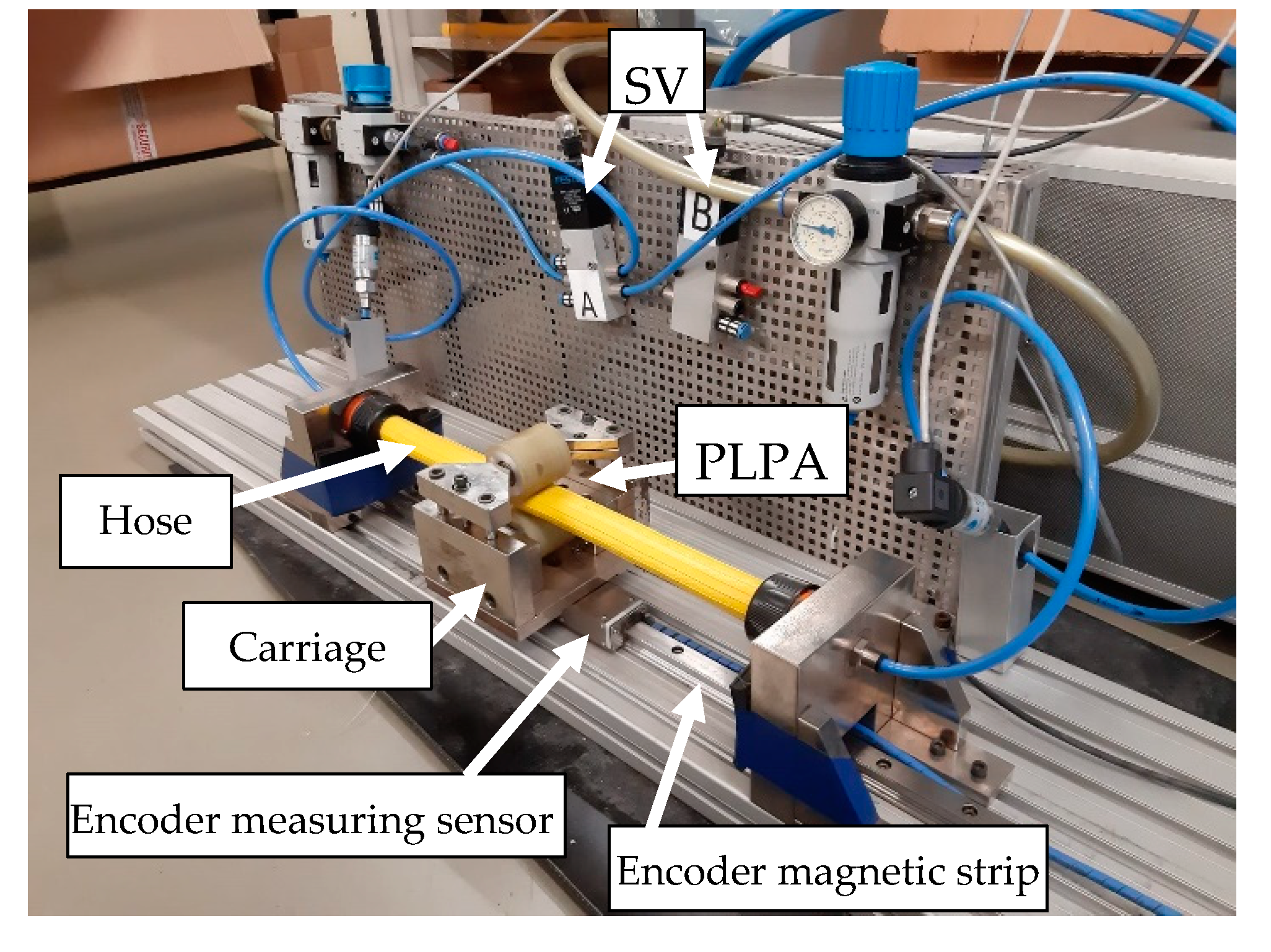
The experimental setup used in this work is depicted in Figure 1. It comprises a PLPA mounted on a carriage, which runs over a monorail guidance system with an integrated position encoder (Bosch Rexroth IMS series). This encoder has a 5 μm resolution, ±0.75 μm interpolation accuracy and ±0.25 μm repeatability. In addition, the setup includes two FESTO servo-valves (SV) MPYE-5-1/8-HF-010-B The described valves and sensors are connected to a data acquisition and control system comprising a PC with data acquisition boards and all the necessary signal conditioning hardware.
The two aluminum rollers on the PLPA have a urethane coating to reduce the stress in the hose. The bottom roller is fixed to the carriage while the top one’s height is adjustable with the help of two screws on each side. By using (or not) a set of four spring washers on each of these screws, force (or distance) between the rollers can be imposed. The hose chosen for this study was FLEXIGOM AIR, manufactured by Productos Mesa, the most durable hose tested in [24]. This hose, designed for 30 bar working pressure, is comprised of a flexible nitrile rubber sleeve, reinforced with a high-tenacity polyester fabric and an abrasion-resistant external coating.
3. System Model
The model of the system has been presented in detail in [25] and can be summarized as follows
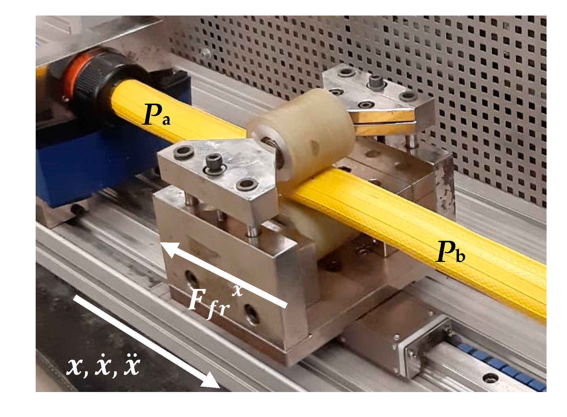
where represents the moving mass, , , represent its position, velocity and acceleration, respectively, represent the pressure acting inside the PLPA chambers A and B, respectively, represents the hose cross-section area, is the total friction force acting on the x direction on the system (see Figure 2), which can be detailed as
where is the friction due to the ball bearings of the rollers, is the friction between the monorail guide and the carriage, is the sliding friction in the transversal direction and is a factor relating the hose flattening velocity in the transversal direction () to the moving mass velocity in the horizontal direction (). was experimentally determined in [25].
Assuming that the pressure inside each of the PLPA chambers is higher than 0.2 bar, the hose’s cross-section can be considered constant [22] and, as such, the roller motion is the unique responsible for the volume change inside each chamber.
Taking this into account and considering that temperature fluctuations over the equilibrium temperature are negligible, the following equation can be written to describe the pressure dynamics of chambers A and B [26]
where represents each chamber’s volume, is the ratio of specific heats for air, the ambient temperature and , the mass flow of air entering and leaving each chamber, respectively. In order to determine the mass flow of air , a balance should be performed between (i) the flow retrieved or delivered by the servo valves ([27,28,29]) and (ii) the leakage flow . In the present work however, the leakage between chambers is negligible, it was experimentally shown in [25]. Under these assumptions, the model for each working port of the servo-valve can be obtained [25]
Equations (1) through (4) define a nonlinear model of the system. This model can be approximated by the following third-order linear model
where are equilibrium constants, is the sliding friction coefficient, is the harmonic mean of the pressure time constants of the PLPA, is the constant of air as a perfect gas, represent each chamber’s temperature, are the flow gain values for each of the servo-valve working ports and is the nonlinear static friction force. It should be noted that in equilibrium conditions . Equation (5) can be further simplified as
where
4. Position Closed Loop Control
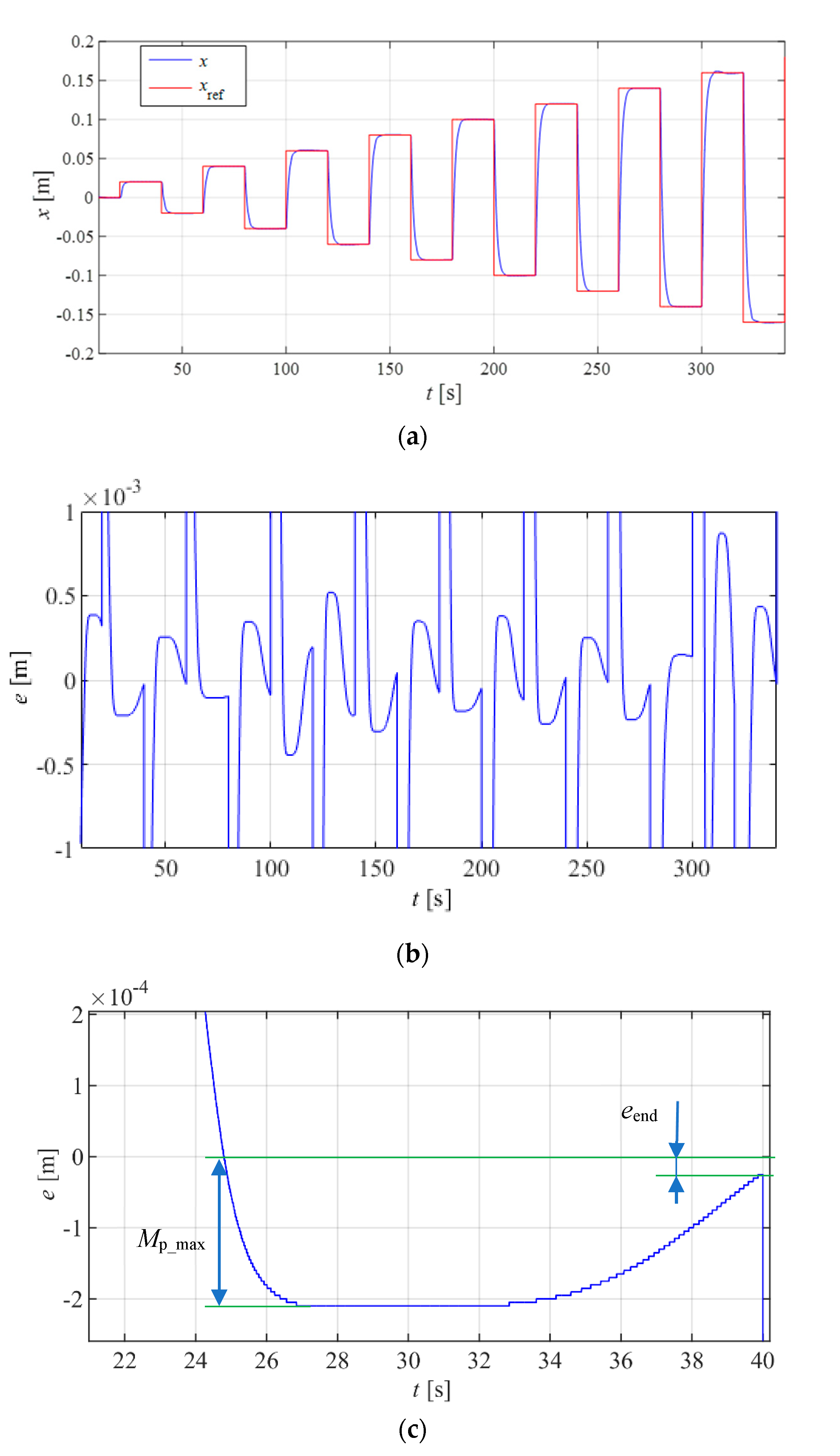
To test the closed loop control of the developed actuator, an increasing amplitude square wave reference signal was used. Each step input had a 20 s duration and between steps the amplitude increase was of 20 mm, up to a maximum of 320 mm, in a total of 16 steps. The error at the end of each step (), overshoot (), settling time to 2% of the step amplitude () and settling time to ±0.1 mm of the set point value (), were registered. At the end of each test, the maximum absolute error () and overshoot () for all steps were registered, as well as the average settling times ( and ) and respective standard deviation ( e ).
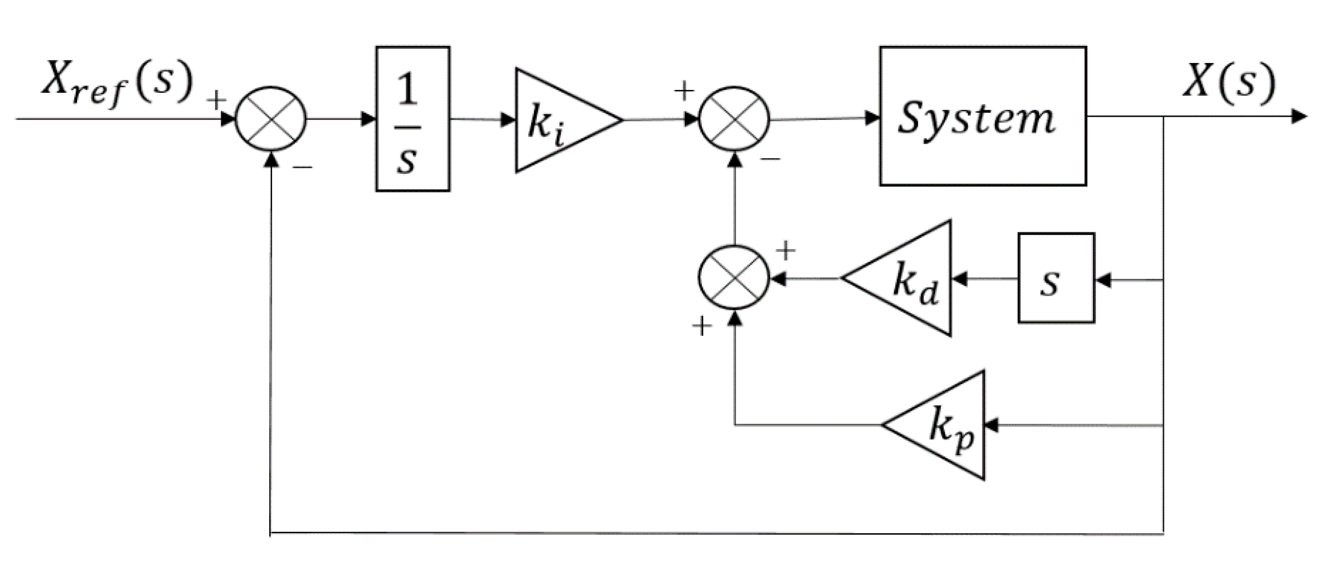
Several controllers were tested. Given its simplicity and its wide usage in industrial environments, a controller from the PID family, an I-PD [30] controller in the present case, was the first one to be tested. The I-PD controller block diagram is shown in Figure 3. The controller parameters were initially determined using Ziegler–Nichols tuning rules and then experimentally fine-tuned. Figure 4 shows the systems output position and error, and Table 2 presents the performance metrics obtained.
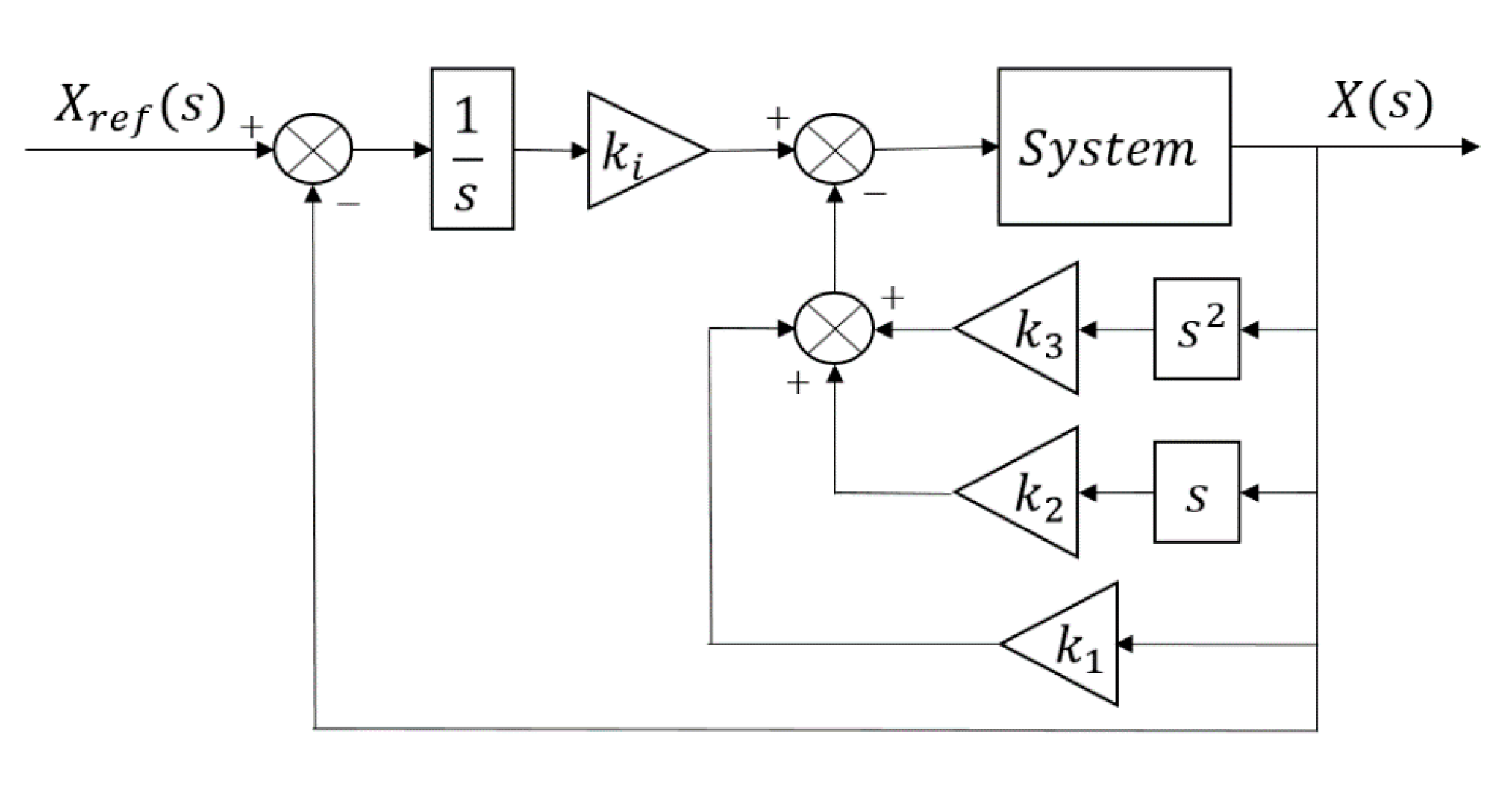
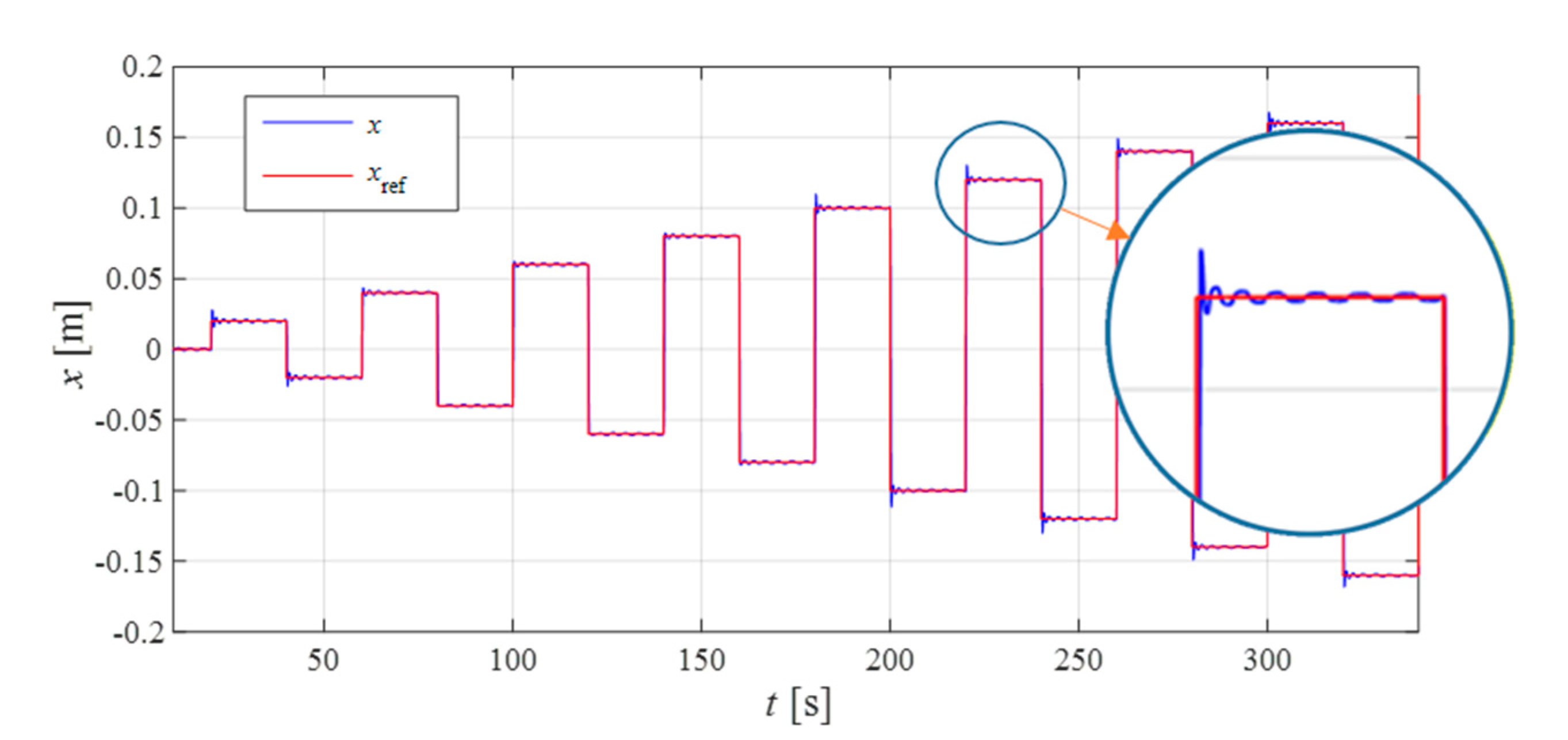
Figure 4 shows that the response speed of the system is slow, being unable to reach the ±0.1 mm range in some of the 20 s steps. In order to accelerate the system, a state feedback controller with integral action (SFCI) was tested. The controlled system block diagram is presented in Figure 5. The SFCIs parameters were chosen to impose a 4th order Bessel filter dynamic with a characteristic frequency of . The systems output position is displayed in Figure 6.
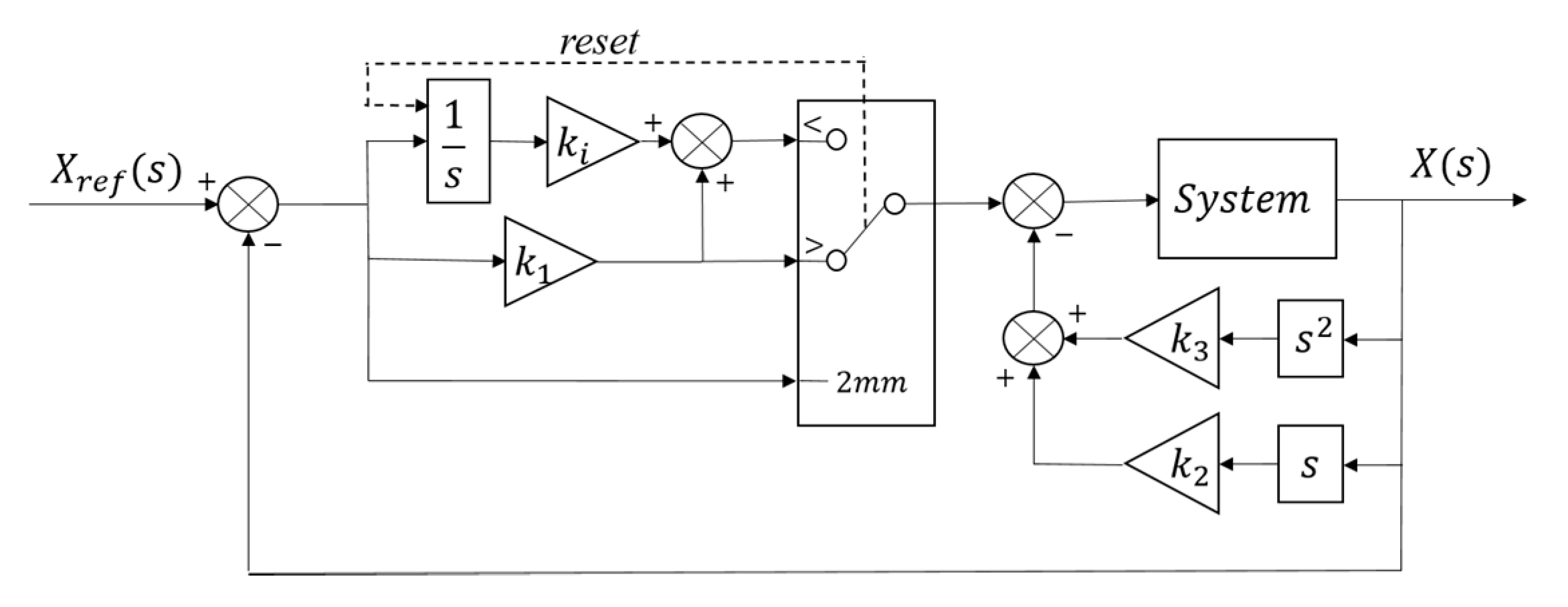
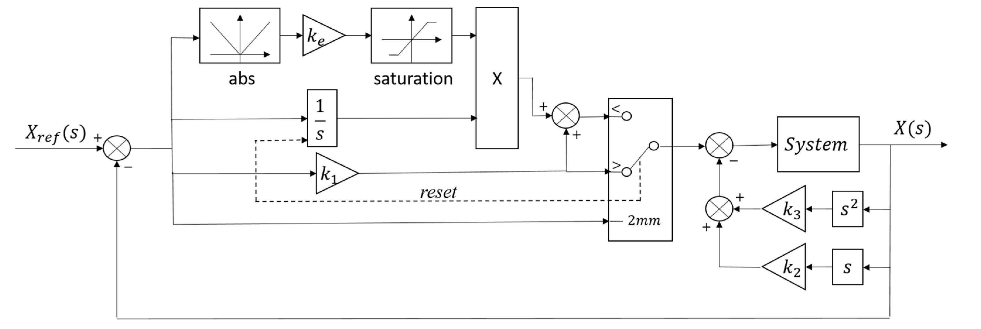
From the results presented in Figure 6, it is seen that system response is quicker, but a limit cycle occurs with the SFCI. To circumvent this problem, a state feedback controller was designed where an integral action is added whenever the system is inside a pre-specified error range (SFC+I). This controller behaves as a regular state feedback controller (SFC) whenever it is outside the error range and as a PI-DD2 whenever it is inside it. In this work, an error range of δ = ±2 mm was experimentally selected, since the SFC can ensure this positioning tolerance. Figure 7 presents the block diagram of the SFC+I controller. The controller parameters were chosen to make the system behave as a 3rd order Bessel filter () when outside the error range. The integral action gain () was experimentally tuned and is reset whenever the error is outside the error band, as represented in Figure 7. The results are shown in Figure 8 and the performance metrics are displayed in Table 3.
Comparing the values presented in Table 2 and Table 3, this control strategy allowed the PLPA response to become faster, taking about an eighth of the time to reach the 2% range.
One way to reduce the time required to reach the 0.1 mm range would be to increase the integral gain, . However, it was found that by doing so, the system started to show limit cycle behavior. In order to make it faster and circumvent limit cycle limitations, the integral action was modulated according to (10):
Gain was experimentally tuned while gain was kept at the same value as . This was done because when Equation (10) is saturated, the control law is the same as in the previous case tested. The final controller architecture (SFC+IM) is shown in Figure 9.
5. Results Discussion
From the several controllers considered in this work, the SFCI controller was the only one leading to a limit cycle. It is known that even without Stribeck friction, a limit cycle can occur whenever an integral action is present [31]. Furthermore, as also shown in [31], the limit cycle can occur for a given set of controller parameters and not occur for another set of parameters. This situation happened in the present study, since the I-PD is a particular case of the SFCI controller (with ), and while the SFCI exhibited limit cycles, the I-PD did not.
Table 5 sums up the performance of the controllers tested in this paper. From this table it can be clearly seen that the I-PD controller achieves much lower overshoot values than the remaining ones. However, it is a very slow controller, taking more than twice the time of the SFC+I and ten times the duration of the SFC+IM to reach the 0.1 mm error band.
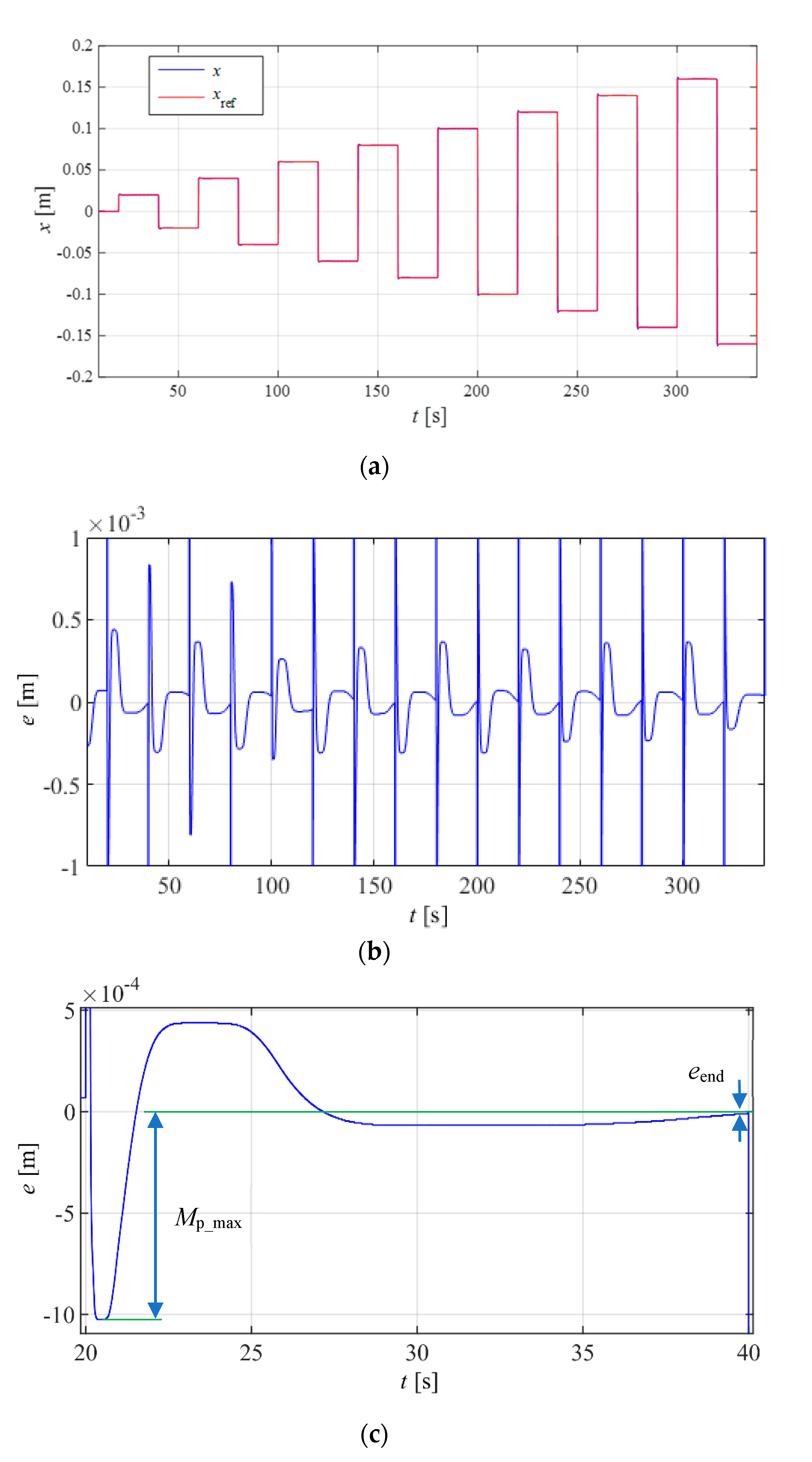
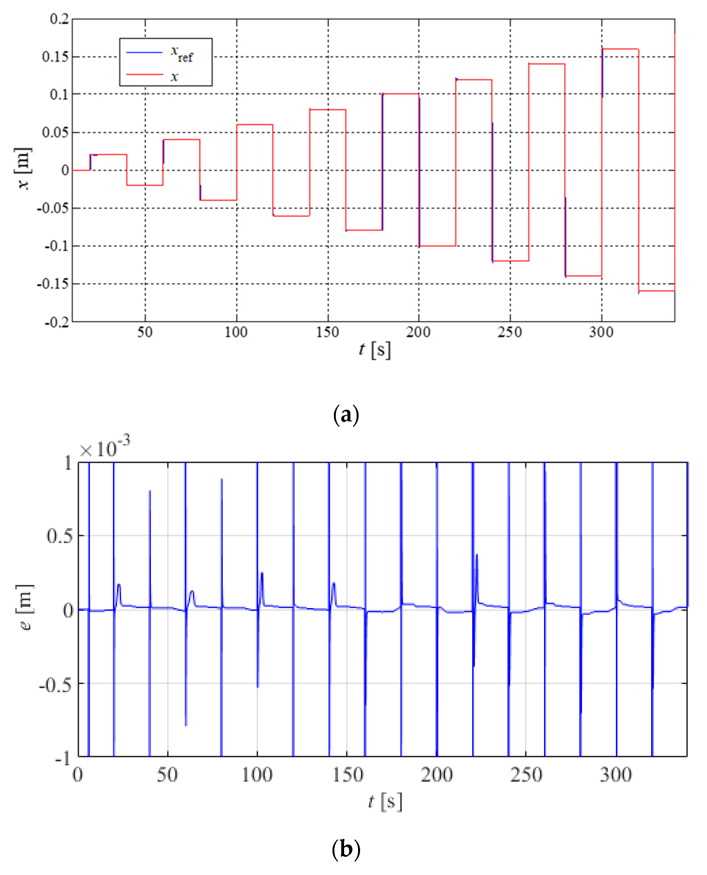
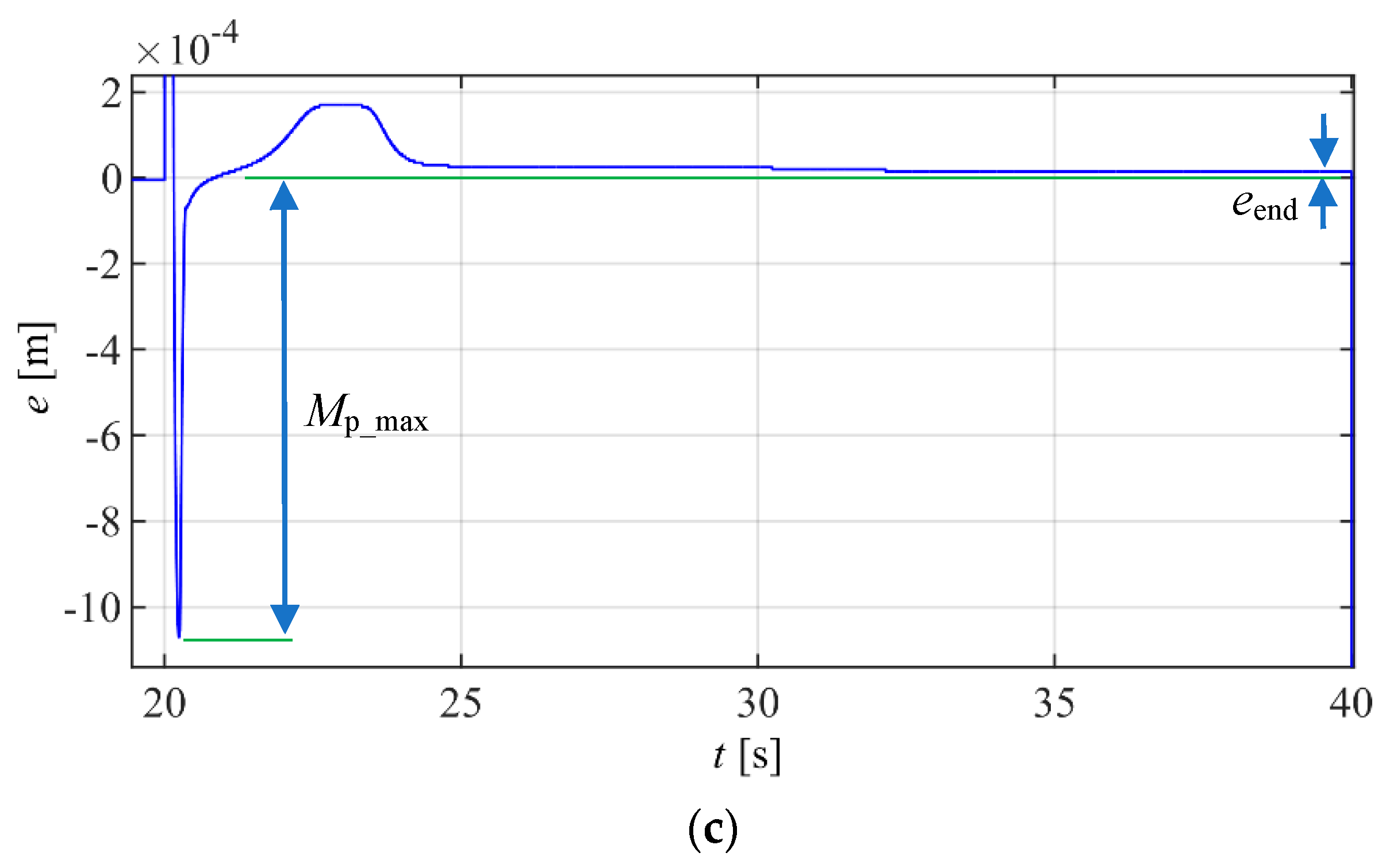
The introduction of the modulated integral gain, in the SFC+IM controller, clearly improved the performance of the system behavior when compared to the one obtained with the SFC+I controller. The time to reach the 0.1 mm range was considerably diminished from 6.7 to 1.67 s, the maximum error was reduced from 45 to 15 μm, while the overshoot remained essentially the same. It is therefore believed that the controller proposed in this work (SFC+IM), when compared to PID-based controllers, leads to a better compromise between overshoot and settling time. However, this controller requires more parameters, making the tuning of the controller more difficult. Future work will therefore focus on adaptive parameter-tuning methodologies.
6. Conclusions
This paper has presented the servo control of a linear peristaltic pneumatic actuator where the force between rollers is imposed. The linear and nonlinear models of the system were presented. A new linear-based controller was developed and compared with datum controllers already used in the literature with peristaltic linear actuators. The new controller developed in this work leads to a much faster response while avoiding limit cycles. The average time required to reach a 0.1 mm error band was 1.67 s, in an experiment consisting of a series of 16 steps ranging from 0.02 to 0.32 m in amplitude. These results are comparable with the ones achieved using conventional piston actuators, thereby showing that linear peristaltic actuators may be an effective alternative. Future work will focus on the development of different hoses geometries and materials that might increase the service life.
Author Contributions
Conceptualization, J.F.C. and F.G.d.A.; methodology, J.F.C. and F.G.d.A.; software, J.B.P., J.F.C.; validation, J.F.C., J.B.P. and F.G.d.A.; investigation, J.F.C., J.B.P. and F.G.d.A.; resources, J.F.C., J.B.P., and F.G.d.A.; writing—original draft preparation, J.F.C.; writing—review and editing, J.F.C., J.B.P. and F.G.d.A.; All authors have read and agreed to the published version of the manuscript.
Funding
This work was financially supported through contract LAETA – UIDB/50022/2020 by “Fundação para a Ciência e Tecnologia”, which the authors gratefully acknowledge.
Conflicts of Interest
The authors declare no conflicts of interest.
References
- Saleem, A.; Abdrabbo, S.; Tutunji, T. On-line identification and control of pneumatic servo drives via a mixed-reality environment. Int. J. Adv. Manuf. Technol. 2009, 40, 518–530. [Google Scholar] [CrossRef]
- Takosoglu, J.; Dindorf, R.; Laski, P. Rapid prototyping of fuzzy controller pneumatic servo-system. Int. J. Adv. Manuf. Technol. 2009, 40, 349–361. [Google Scholar] [CrossRef]
- Pu, J.; Weston, R.H. Motion Control of Pneumatic Drives. Microprocess. Microsyst. 1988, 12, 373–382. [Google Scholar] [CrossRef]
- Ionnidis, I.; Nguyen, T. Microcomputer-controlled servo-pneumatic drives. In Proceedings of the Seventh International Fluid Power Symposium, Bath, England, 16–18 September 1986; pp. 155–164. [Google Scholar]
- Ning, S.; Bone, G. High Steady-State Accuracy Pneumatic Servo Positioning System with PVA/PV Control and Friction Compensation. In Proceedings of the 2002 IEEE International Conference on Robotics and Automation, Washington, DC, USA, 11−15 May 2002; pp. 2824–2829. [Google Scholar]
- Carneiro, J.F.; Almeida, F.G. A high accuracy trajectory following controller for pneumatic devices. Int. J. Adv. Manuf. Technol. 2012, 61, 253–267. [Google Scholar] [CrossRef] [Green Version]
- Falcão Carneiro, J.; Gomes de Almeida, F. A macro-micro motion servopneumatic device. Proc. Inst. Mech. Eng. Part I J. Syst. Control Eng. 2012, 226, 775–786. [Google Scholar]
- Zu, Y.; Barth, E. Accurate Sub-Millimeter Servo-Pneumatic Tracking using Model Reference Adaptive Control (MRAC). Int. J. Fluid Power 2010, 11, 43–55. [Google Scholar]
- Falcão Carneiro, J.; Gomes de Almeida, F. Accurate motion control of a servopneumatic system using integral sliding mode control. Int. J. Adv. Manuf. Technol. 2014, 77, 1533–1548. [Google Scholar] [CrossRef]
- Falcão Carneiro, J.; Gomes de Almeida, F. Micro tracking and positioning using off-the-shelf servopneumatics. Robot. Comput. Integr. Manuf. 2014, 30, 244–255. [Google Scholar] [CrossRef]
- Falcão Carneiro, J.; Gomes Almeida, F. On the influence of velocity and acceleration estimators on a servopneumatic system behaviour. IEEE Access 2016, 4, 6541–6553. [Google Scholar] [CrossRef]
- Mori, S.; Tanaka, K.; Nishikawa, S.; Niiyama, R.; Kuniyoshi, Y. High-Speed Humanoid Robot Arm for Badminton Using Pneumatic-Electric Hybrid Actuators. IEEE Robot. Autom. Lett. 2019, 4, 3601–3608. [Google Scholar] [CrossRef]
- Rouzbeh, B.; Bone, G.; Graham, A.; Li, E. Design, Implementation and Control of an Improved Hybrid Pneumatic-Electric Actuator for Robot Arms. IEEE Access 2018, 7, 14699–14713. [Google Scholar] [CrossRef]
- Merkelbach, S.; Murrenhoff, I.H.; Fey, I.M.; Eßer, B. Pneumatic or electromechanical drives—A comparison regarding their exergy efficiency. In Proceedings of the 10th International Fluid Power Conference, Dresden, Germany, 8–10 March 2016; pp. 103–115. [Google Scholar]
- Gauchel, W.; Haag, S. Servopneumatic Clamping System for the Assembly of Battery Cells in the Area of Electromobility. In Proceedings of the 10th International Fluid Power Conference, Dresden, Germany, 8–10 March 2016; pp. 137–148. [Google Scholar]
- Pinto, J.B. Desenvolvimento de Controlador de Movimento para Cilindro Pneumático de Baixo Atrito. Master's Thesis, Departamento de Engenharia Mecânica, Faculdade de Engenharia da Universidade do Porto, Porto, Portugal, 2017. [Google Scholar]
- Rakova, E.; Hepke, J.; Weber, J. EXonomy analysis for the Inter-domain comparison of electromechanical and pneumatic drives. In Proceedings of the 10th International Fluid Power Conference, Dresden, Germany, 8–10 March 2016; pp. 117–135. [Google Scholar]
- Li, S.; Vogt, D.; Bartlett, N.; Rus, D.; Wood, R. Tension Pistons: Amplifying Piston Force Using Fluid-Induced Tension in Flexible Materials. Adv. Funct. Mater. 2019, 29, 1901419. [Google Scholar] [CrossRef]
- Stoll, J.T.; Schanz, K.; Pott, A. Mechatronic Control System for a Compliant and Precise Pneumatic Rotary Drive Unit. Actuators 2020, 9, 1. [Google Scholar] [CrossRef] [Green Version]
- Tomori, H.; Hiyoshi, K. Control of Pneumatic Artificial Muscles Using Local Cyclic Inputs and Genetic Algorithm. Actuators 2018, 7, 36. [Google Scholar] [CrossRef] [Green Version]
- Sekine, M.; Kokubun, R.; Yu, W. Investigating the Effect of a Mechanism Combined with a Speed-Increasing Gear and a Pneumatic Artificial Muscle. Actuators 2018, 7, 22. [Google Scholar] [CrossRef] [Green Version]
- Falcão Carneiro, J.; Gomes de Almeida, F. Experimental characteristics of a linear peristaltic actuator. In Proceedings of the IFK 2018 11th International Fluid Power Conference, Aachen, Germany, 19–21 March 2018. [Google Scholar]
- Falcão Carneiro, J.; Gomes de Almeida, F. Friction characteristics and servo control of a linear peristaltic actuator. Int. J. Adv. Manuf. Technol. 2018, 96, 23. [Google Scholar]
- Carneiro, J.F.; de Almeida, F.G.; Pinto, J.B. Endurance tests of a linear peristaltic actuator. Int. J. Adv. Manuf. Technol. 2019, 100, 2103–2114. [Google Scholar] [CrossRef]
- Carneiro, J.F.; Pinto, J.B.; de Almeida, F.G.; Fateri, M. Model and Experimental Characteristics of a Pneumatic Linear Peristaltic Actuator. Information 2020, 11, 76. [Google Scholar]
- Carneiro, J.F.; de Almeida, F.G. Reduced-order thermodynamic models for servo-pneumatic actuator chambers. Proc. Inst. Mech. Eng. Part I J. Syst. Control Eng. 2006, 220, 301–314. [Google Scholar] [CrossRef] [Green Version]
- Carneiro, J.F.; Almeida, F.G. Pneumatic servo valve models based on artificial neural networks. Proc. Inst. Mech. Eng. Part I J. Syst. Control Eng. 2011, 225, 393–411. [Google Scholar]
- Carneiro, J.F.; Almeida, F.G. A Neural Network Based Nonlinear Model of a Servopneumatic System. ASME J. Dyn. Syst. Meas. Control 2012, 134, 024502. [Google Scholar] [CrossRef]
- Varga, Z.; Honkola, P.-K. Mathematical model of pneumatic proportional valve. J. Appl. Sci. Thermodyn. Fluid Mech. 2012, 1, 1. [Google Scholar]
- Ogata, K. Modern Control Engineering, 4th ed.; Prentice Hall: Upper Saddle River, NJ, USA, 2001. [Google Scholar]
- Olsson, H.; Astrom, K. Friction Generated Limit Cycles. IEEE Trans. Control Syst. Technol. 2001, 9, 629–636. [Google Scholar] [CrossRef] [Green Version]
Figure 1.
Experimental setup.

Figure 2.
Mechanical model nomenclature.

Figure 3.
Block diagram of the I-PD controller.

Figure 4.
I-PD positioning test results: (a) position vs. reference; (b) error evolution in time; (c) detail of (b), showing the step where Mp_max occurred.
Figure 4.
I-PD positioning test results: (a) position vs. reference; (b) error evolution in time; (c) detail of (b), showing the step where Mp_max occurred.

Figure 5.
Block diagram of the state feedback controller with integral action (SFCI) controller.

Figure 6.
SFCI controller positioning test results: position vs. reference.

Figure 7.
Block diagram of the SFC+I controller.

Figure 8.
SFC+I controller positioning test results: (a) position vs reference; (b) error evolution in time; (c) detail of (b), showing the step where Mp_max occurred.
Figure 8.
SFC+I controller positioning test results: (a) position vs reference; (b) error evolution in time; (c) detail of (b), showing the step where Mp_max occurred.

Figure 9.
Block diagram of the SFC+IM controller.

Figure 10.
SFC+IM controller positioning test results: (a) position vs. reference; (b) error evolution in time; (c) detail of (b), showing the step where Mp_max occurred.
Figure 10.
SFC+IM controller positioning test results: (a) position vs. reference; (b) error evolution in time; (c) detail of (b), showing the step where Mp_max occurred.


Table 1.
Identified system parameters.
| System Parameter | Value | Unit |
|---|---|---|
| [rad/s] | 16.7 | [rad/s] |
| 0.51 | - | |
| [m/(Vs)] | 0.82 | [m/(Vs)] |
Table 2.
I-PD controller performance metrics.
| 210 | 0.9 | 4.22 | 0.18 | 16.66 * | 2.59 * |
* In 5 of the 16 steps, the error was bigger than 0.1 mm. These steps were not considered for the calculation of and .
Table 3.
SFC+I controller performance metrics.
| 45 | 5.08 | 0.53 | 1.18 | 6.7 | 0.75 |
Table 4.
SFC+I controller with new integral law performance metrics.
| 45 | 5.08 | 0.53 | 1.18 | 6.7 | 0.75 |
Table 5.
Positioning performance metrics: comparison between different controllers.
| Controller | ||||||
|---|---|---|---|---|---|---|
| I-PD | 210 | 0.9 | 4.22 | 0.18 | 16.66 * | 2.59 * |
| SFC+I | 45 | 5.08 | 0.53 | 1.18 | 6.7 | 0.75 |
| SFC+IM | 15 | 5.43 | 0.25 | 0.04 | 1.67 | 1.42 |
* Not considering steps in which the error was bigger than ± 0.1 mm.
© 2020 by the authors. Licensee MDPI, Basel, Switzerland. This article is an open access article distributed under the terms and conditions of the Creative Commons Attribution (CC BY) license (http://creativecommons.org/licenses/by/4.0/).
Share and Cite
MDPI and ACS Style
Falcão Carneiro, J.; Bravo Pinto, J.; Gomes de Almeida, F. Accurate Motion Control of a Pneumatic Linear Peristaltic Actuator. Actuators 2020, 9, 63. https://0-doi-org.brum.beds.ac.uk/10.3390/act9030063
AMA Style
Falcão Carneiro J, Bravo Pinto J, Gomes de Almeida F. Accurate Motion Control of a Pneumatic Linear Peristaltic Actuator. Actuators. 2020; 9(3):63. https://0-doi-org.brum.beds.ac.uk/10.3390/act9030063
Chicago/Turabian StyleFalcão Carneiro, João, João Bravo Pinto, and Fernando Gomes de Almeida. 2020. "Accurate Motion Control of a Pneumatic Linear Peristaltic Actuator" Actuators 9, no. 3: 63. https://0-doi-org.brum.beds.ac.uk/10.3390/act9030063
Note that from the first issue of 2016, this journal uses article numbers instead of page numbers. See further details here.