Active Mass Damper for Reducing Wind and Earthquake Vibrations of a Long-Period Bridge


Department of Civil Engineering, Gwangju University, 277 Hyodeck-ro, Nam-gu, Gwangju 61743, Korea
Actuators 2020, 9(3), 66; https://0-doi-org.brum.beds.ac.uk/10.3390/act9030066
Submission received: 30 June 2020
/
Revised: 3 August 2020
/
Accepted: 5 August 2020
/
Published: 7 August 2020
Abstract
:An active mass damper (AMD) was developed that uses a linear motor and coil spring to reduce the vertical vibration of a long-period cable-stayed bridge subjected to wind and earthquake loads. A scaled-down bridge model and AMD were fabricated, and the control effect of the AMD was investigated experimentally and analytically. The AMD was controlled via a linear quadratic Gaussian algorithm, which combines a linear quadratic regulator and Kalman filter. The dynamic properties were investigated using a 1/10 scale indoor experimental model, and the results confirmed that the measured and analytical accelerations were consistent. A vibrator was used to simulate the wind-induced vibration, and the experimental and analytical results were consistent. The proposed AMD was confirmed to damp the free vibration and harmonic load and increase the damping ratio of the bridge model from 0.17% to 9.2%. Finally, the control performance of the proposed AMD was numerically investigated with the scaled-down bridge model subjected to the El Centro and Imperial Valley-02 earthquakes. These results were compared with those of a TMD, and they confirmed that the proposed AMD could reduce excessive vertical vibrations of long-period cable-stayed bridges subjected to wind and earthquakes.
1. Introduction
Long-span bridges such as suspension and cable-stayed bridges are constructed in various forms to connect islands to the mainland or other islands. However, these slender bridges can have problems with wind, earthquake, or vehicle vibration because of their low damping ratios. Frequent vibration of the bridge girders increases the fatigue load and causes user anxiety. Thus, measures are taken to prevent harmful vibrations (e.g., vortex, buffering, and flutter vibration) during the design stage, which include aerodynamic and structural dynamic methods. Aerodynamic methods include changing the flow of air by improving the aerodynamics of the girders with attachments such as fairing, spoilers, or flaps [1,2]. Structural dynamic methods include using devices such as the tuned mass damper (TMD) or active mass damper (AMD) to increase the damping of structures. The TMD is a system of mass, damping, and stiffness that reduces girder vibration by oscillating instead of the girder. The AMD uses electrical forces such as servomotors or actuators to reduce the structural vibration.
Den Hartog [3] proposed the TMD to optimize the frequency and damping ratios for harmonic loads; since then, the TMD has been applied by many researchers in various fields such as buildings, bridges, and industrial facilities to compensate for various external forces [4,5,6,7]. Many researchers have studied developing and applying TMDs to reduce the vibration of bridges subjected to wind loads [8,9,10,11]. Gu et al. [8] designed a TMD with the optimal frequency ratio and damping ratio to reduce the buffering of a cable-stayed bridge due to wind load and applied it to the full-scale bridge. Xing et al. [9] used ANSYS to evaluate the displacement of the girder of the Sutong cable-stayed bridge with auxiliary piers and a TMD and observed a greater damping effect when only the TMD was applied without the auxiliary piers. Domaneschi et al. [10] designed a TMD to reduce the damping vibration of suspension bridges subjected to wind loads and compared the vibration control performance to that of friction dampers. Wang et al. [11] proposed a single-side pounding tuned mass damper (SS-PTMD) to reduce vortex vibrations of bridge decks and applied it to a two-dimensional wind tunnel test model, which reduced the amplitude of the vortex vibration by 94%.
Several studies have focused on reducing the vibration of bridges subjected to external forces such as vehicles, railways, and earthquakes. Pourzeynali et al. [12] proposed a TMD to reduce the vertical vibration of a suspension bridge subjected to an earthquake and derived the optimal values by studying the parameters of the TMD. Fiebig [13] applied a TMD to pedestrian bridges to reduce vibrations and reviewed the vibration control performance according to the theoretical formula. Debnath et al. [14] proposed multiple TMDs (MTMD) to reduce the responses in the vertical, horizontal, and torsional modes of a bridge subjected to vehicle and wind loads and presented the control performance by using the frequency response function (FRF) of the bridge with and without MTMD. Yin et al. [15] proposed a pounding tuned mass damper (PTMD) to reduce the dynamic response of the highway to wind and vehicle loads and numerically simulated the effects of installing multiple PTMDs in each bridge span on the mid-span reductions in the horizontal and vertical displacements. Chen et al. [16] studied the horizontal vibration of bridges caused by train operation in the event of an earthquake and simulated the train and railway bridge with multibody dynamics and a finite element analysis program. Nugroho et al. [17] proposed a TMD to reduce the vibration of the bridge caused by the train speed and showed that the response of the bridge with the TMD satisfied the comfort criteria. Although many studies have focused on reducing the vibration of bridges subjected to external loads, it is not easy to design a TMD for long-period bridges.
Another approach to minimize the vibration of the bridges is to apply an AMD. The AMD is an active control, which includes algorithms such as the classical optimal control, neural network control, fuzzy theory, and mixing method. Active devices include the active tendon, magnetorheological (MR) damper, and AMD. El Ouni et al. [18,19] numerically and experimentally studied controlling the vertical vibration of girders by using the active tendon force of the cable with a laboratory-scale cable-stayed bridge model. Crusells-Girona and Aparicio [20] proposed an active control algorithm that adjusts the axial force of the cables in a cable-stayed bridge to reduce the girder displacement and stress. Soneji and Jangid [21] performed finite element analysis and used MR dampers with high damping rubber bearings to reduce the longitudinal displacement of cable-stayed bridges during earthquakes. Ok et al. [22] proposed a semi-active fuzzy control algorithm for controlling MR dampers and compared the control performances of semi-active, active, and hybrid control algorithms for cable-stayed bridges. Pourzeynali et al. [12] installed an MR damper diagonally between the tower and girder of a suspension bridge subjected to an earthquake and showed that the vibration was reduced in numerical simulations. Soto and Adeli [23] applied MR dampers to reduce the displacement of highway bridges during an earthquake and compared the results with passive, semiactive, and active controls. Soares et al. [24] applied the neuro-fuzzy and simple adaptive control algorithms to MR dampers to reduce the shear force of the pylons of a cable-stayed bridge during an earthquake. Scheller and Starossek [25] used a twin-rotor damper to reduce the vibration of a bridge due to wind loads and performed a wind tunnel test to show that the damping of the bridge was increased. Zhang et al. [26] also demonstrated the vibration reduction performance of the twin-rotor damper against wind and seismic loads. Goorts et al. [27] proposed an electromechanical mass damper (EMD) to reduce the horizontal vibration of bridges and performed a hybrid simulation using a shaking table test and simulation results to demonstrate the reduced horizontal displacement. Setio and Gunawan [28] proposed an AMD that uses an artificial neural network algorithm to control the vertical vibration of a cable-stayed girder during an earthquake, and their numerical simulations showed that the relative displacement between the centers of the pylon and girder was reduced.
In this study, an AMD was developed to reduce the vertical vibration of a cable-stayed bridge girder subjected to wind and earthquake loads. A scaled-down bridge model and AMD were fabricated, and the active control performance of the proposed AMD was experimentally and numerically investigated. Section 2 describes the linear quadratic Gaussian (LQG) control algorithm, which combines a linear quadratic regulator (LQR) and Kalman filter and was used to control the AMD. Section 3 presents details on the target bridge, scaled-down bridge model, and AMD. Section 4 presents the equation of motion, system identification, and numerical and experimental results for verifying the AMD control performance as well as the effectiveness of the proposed AMD against earthquakes. Finally, Section 5 summarizes the main contents of this study.
2. LQG Control Algorithm
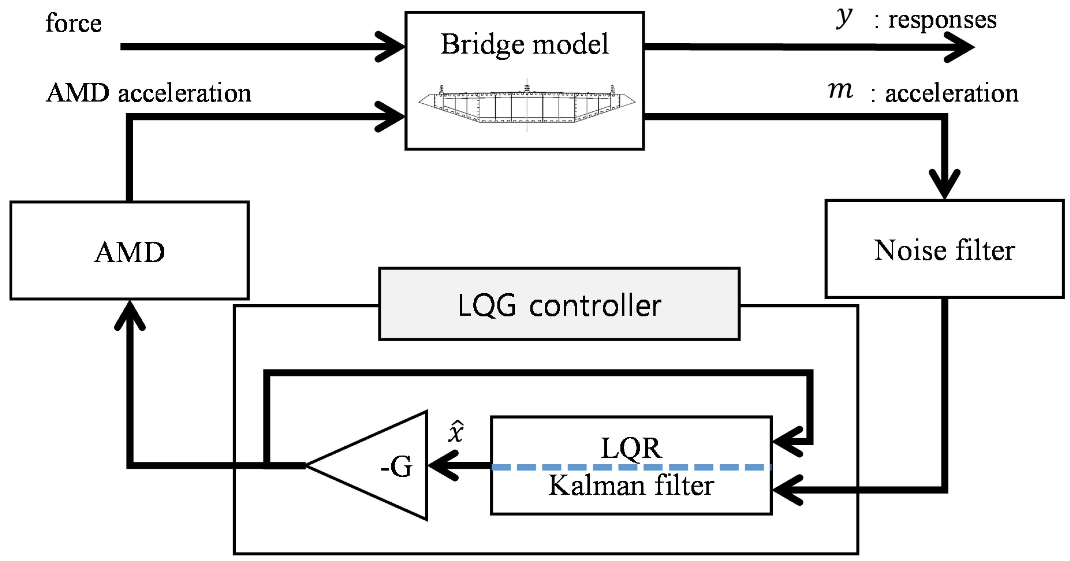
To calculate the proper control force, the AMD needs a control algorithm, which is a series of processes for calculating the behavior of the control device to control the response of the target system based on measurements from a sensor or the current state information of the control device. If the mathematical modeling of the target system is accurate and linear, the LQG linear optimal control technique can be used, which combines LQR control and the Kalman filter. Figure 1 shows a block diagram of the LQG controller. The LQR calculates the control gain for optimal control, and the Kalman filter estimates the state vectors for practical application.
If the system is linearly time-invariant, the equation of motion can be expressed in the form of a state space [29,30,31,32]:
where is the state variable vector, is the control force, is the external force, is the output vector, and are system matrices, and , , , and are position matrices with respect to the control and external forces. The control force is calculated by multiplying the state vector and control gain:
where is the control gain and can be calculated with the LQR control algorithm presented in the next section.
2.1. LQR Controller
The LQR control algorithm finds the optimal control gain that minimizes the performance index:
where and are weight matrices with each magnitude representing the relative importance of the state value and control force of the system. is the final time. To minimize Equation (4), a new objective function is defined that combines Equations (1)–(4):
Summing Equation (5) with the separation of variables method yields
Since are all arbitrary values, the following conditional expressions must be satisfied for Equation (6) to be valid:
The control force is obtained from Equation (8):
Since the control force is obtained from feedbacking the state vector of the system, it can be written as follows:
Therefore, the control force can be expressed as follows:
where is the Riccati matrix and can be determined with Equations (7), (8), (9), and (11).
2.2. Kalman Filter
LQR control has the constraint that all state variables must be known. However, the displacements and velocities at all points of a civil structure are not known. Therefore, the control force needs to be calculated by estimating the overall state variables based on limited measurement information. The system for estimating state variables is called an observer. In this study, the Kalman filter was used to estimate the state variables. The state-space equations for the structure and measurement system are given by
where are measurement values, is sensor noise, and and are system matrices. If the estimated value of the state variable is , the state-space equation for the estimated state variable is given by
where , , and are system matrices. The difference between the state variable and estimated value of the state variable can be defined as the estimation error:
By taking the derivative of time on both sides and substituting Equations (13) and (15) into Equation (16), the error dynamics is given by
Finally, the Kalman filter gain must be determined by using the orthogonality principle on Equation (17).
3. Target Bridge and Scaled-Down Experimental Model
3.1. Cable-Stayed Bridge Model
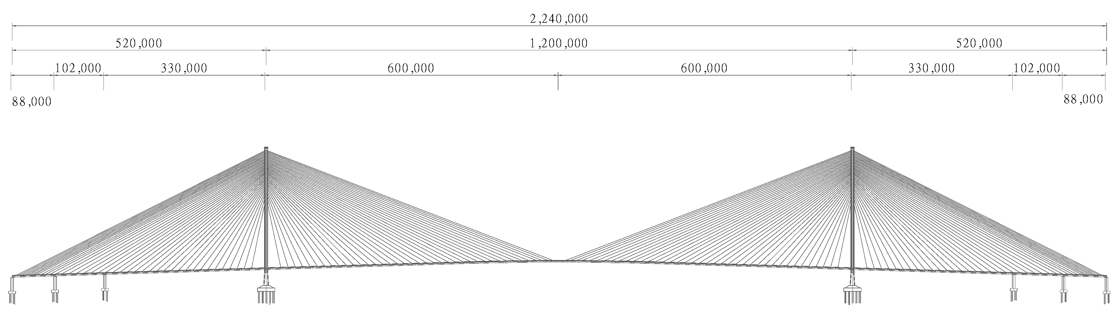
In this study, the 95% construction stage of a cable-stayed bridge was targeted for controlling the vertical vibration. The span was 1200 m, the girder width was 29 m, the girder depth was 4.0 m, and the pylon height was 282 m. The bridge geometry is shown in Figure 2.
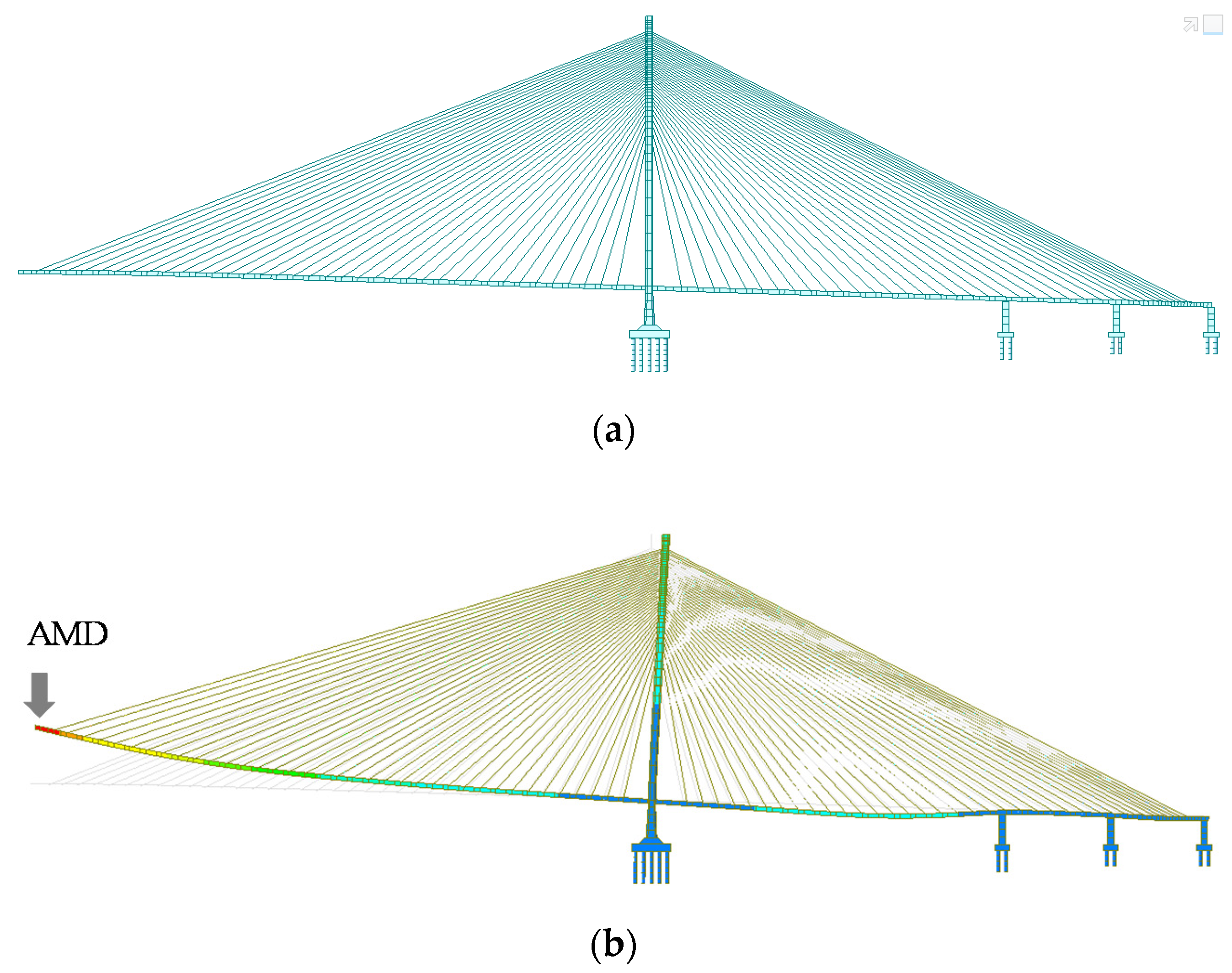
The finite element analysis program MIDAS Civil was used to model the cable-stayed bridge in the 95% construction stage. Eigenvalue analysis was performed, and the frequency of the first vertical mode was confirmed to be 0.167 Hz. Figure 3 shows the finite element model of the 95% construction stage and the first vertical mode shape. To calculate the moving mass of the AMD, it was assumed to be installed at the tip of the girder, and the mode vector of the installation position was normalized to 1. The modal mass of the girder’s vertical mode was calculated to be 1526 tons. As shown in Figure 3b, when the AMD was installed, four AMDs with moving mass of 15 tons were required. Specifications of the actuator for the AMD are shown in Table 1.
3.2. Scaled-Down Experimental Model
The dynamic characteristics of the target bridge were reduced to 1/10.17 scale for verification and simulation of the AMD’s control of the vertical vibration. The mass and frequency of the scaled-down bridge model were calculated according to the similarity law [33]:
where and are the mass and frequency, respectively, of the scaled-down bridge model and and are the modal mass and frequency, respectively, of the prototype bridge. is the scale ratio. The mass and frequency of the scaled-down bridge model are given in Table 2.
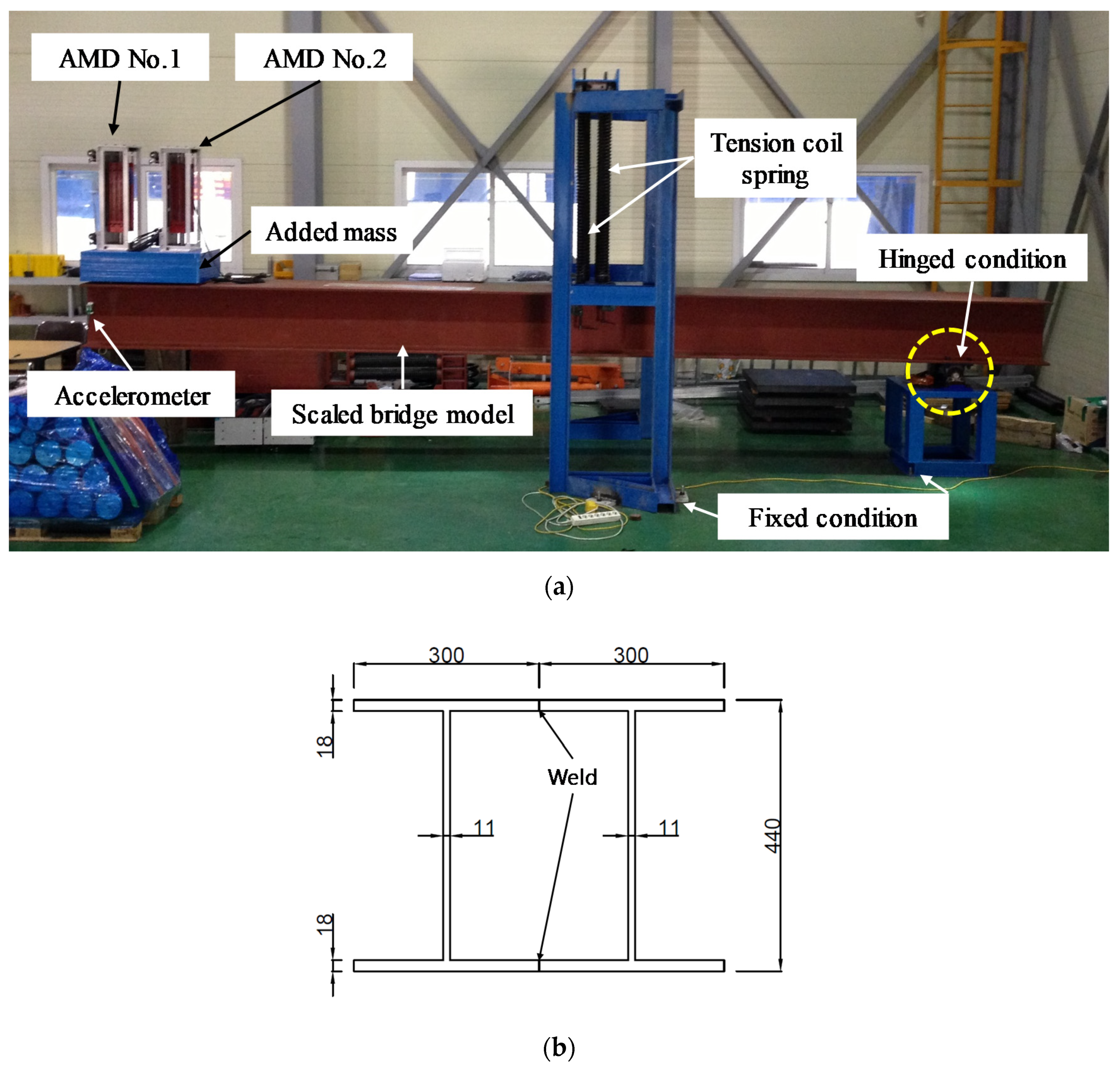
Figure 4 shows the experimental model, which was fabricated from two 6.1-m-long H-beams (450 mm × 300 mm × 11 mm × 18 mm). The yellow circle on the right side of the figure shows the hinge, around which the bridge model could rotate up and down. In addition, the bridge model was connected to the tension spring in the blue frame, and the frequency in the vertical direction was adjusted according to the number of springs and distance from the hinge. The additional mass on the left side of the figure was used to fine-tune the frequency. Two AMDs are shown on the left side of the figure. The first AMD was used as an exciter to simulate wind excitation, and the second AMD was used as a controller to reduce wind vibration. An accelerometer at the tip of the bridge model was used to provide input to the AMD.
3.3. AMD Design and Fabrication
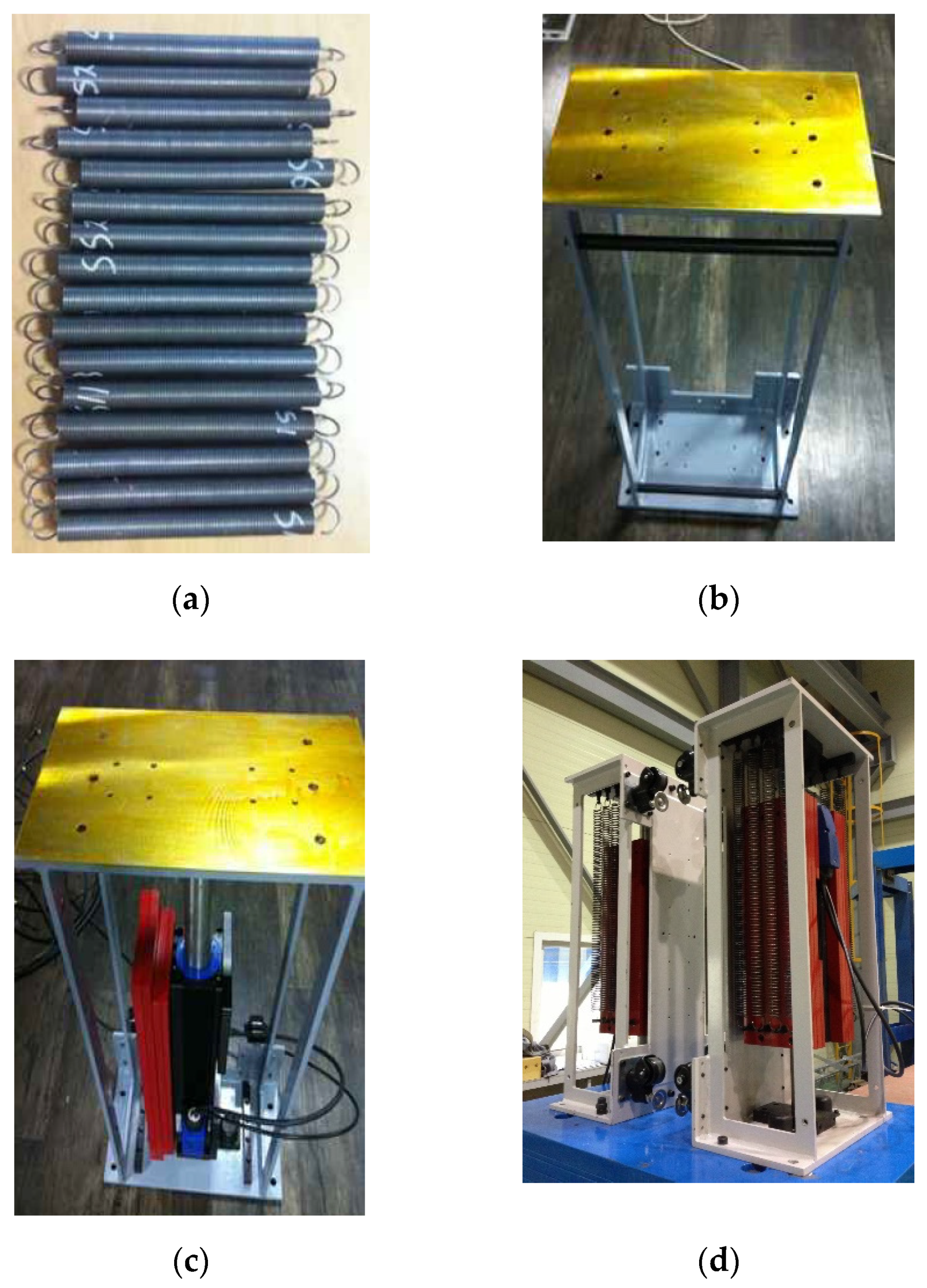
The AMD was designed and fabricated to reduce the vertical vibration of the scaled-down bridge model. The moving mass of the AMD was determined to be 50 kg (3.8%), and the position of the moving mass was adjusted by using tension coil springs to assist the power of the AMD motor. Figure 5 shows the AMD assembly process, which consisted of tension springs, a frame, and a motor. The specifications of the fabricated AMD are given in Table 3.
4. Verification of the Control Performance
4.1. Definition of the Equation of Motion for the Entire System
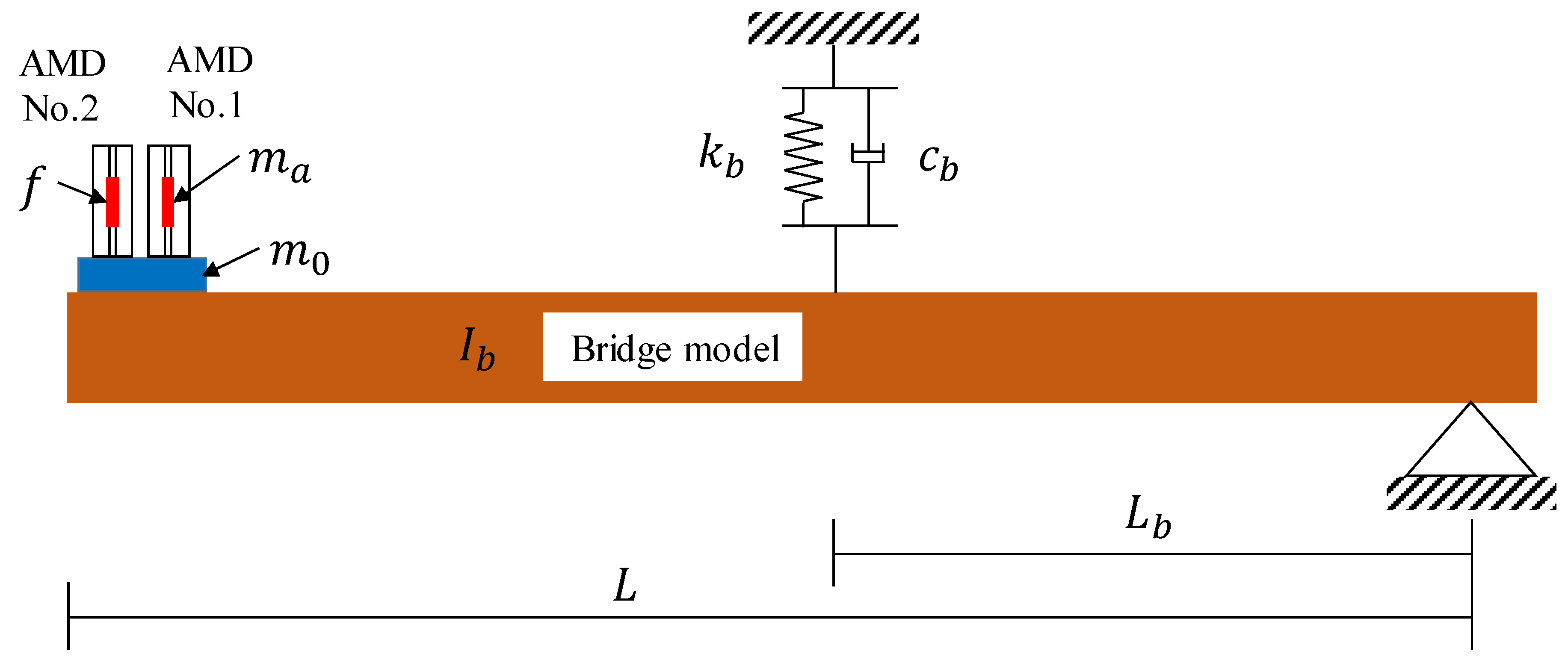
Figure 6 shows a block diagram of the scaled-down bridge system for deriving the equations of motion of the entire system. To simulate the wind load, AMD No. 2 was used as a vibrator to vibrate the bridge model, and AMD No. 1 was used to control the vibration of the bridge model. This AMD was placed at the end of the bridge, where the greatest displacement occurred. Considering the realistic conditions, only the acceleration at the tip was measured for the bridge response.
Designing an LQG controller requires mathematical modeling of the system. The energy of the system is needed to solve its equations of motion [34,35]:
where , , and are the kinetic energy, potential energy, and non-conserved power, respectively; , , and are the mass moment of inertia, added mass, and moving mass of the AMD, respectively; and and are the rotational displacement of the bridge and vertical displacement at the tip, respectively. If the rotational displacement is small, it can be approximated as . and are the length of the bridge and distance from the hinge to the spring, respectively. and are the stiffness and damping, respectively, of the bridge. is an external force. is the absolute displacement of the moving mass of the AMD and can be expressed by , which is the sum of the displacement at the tip of the bridge and the relative displacement of the moving mass of the AMD.
Equations (20)–(22) can be applied to Lagrange’s equation, given in Equation (23), to derive the equation of motion of the entire system, given in Equation (24).
Equation (24) can be simplified to
where , , and are the mass, damping, and stiffness, respectively, of the entire system. Equation (25) can be represented as a state-space equation, given in Equation (26), which can then be simplified to Equation (27).
4.2. System Identification
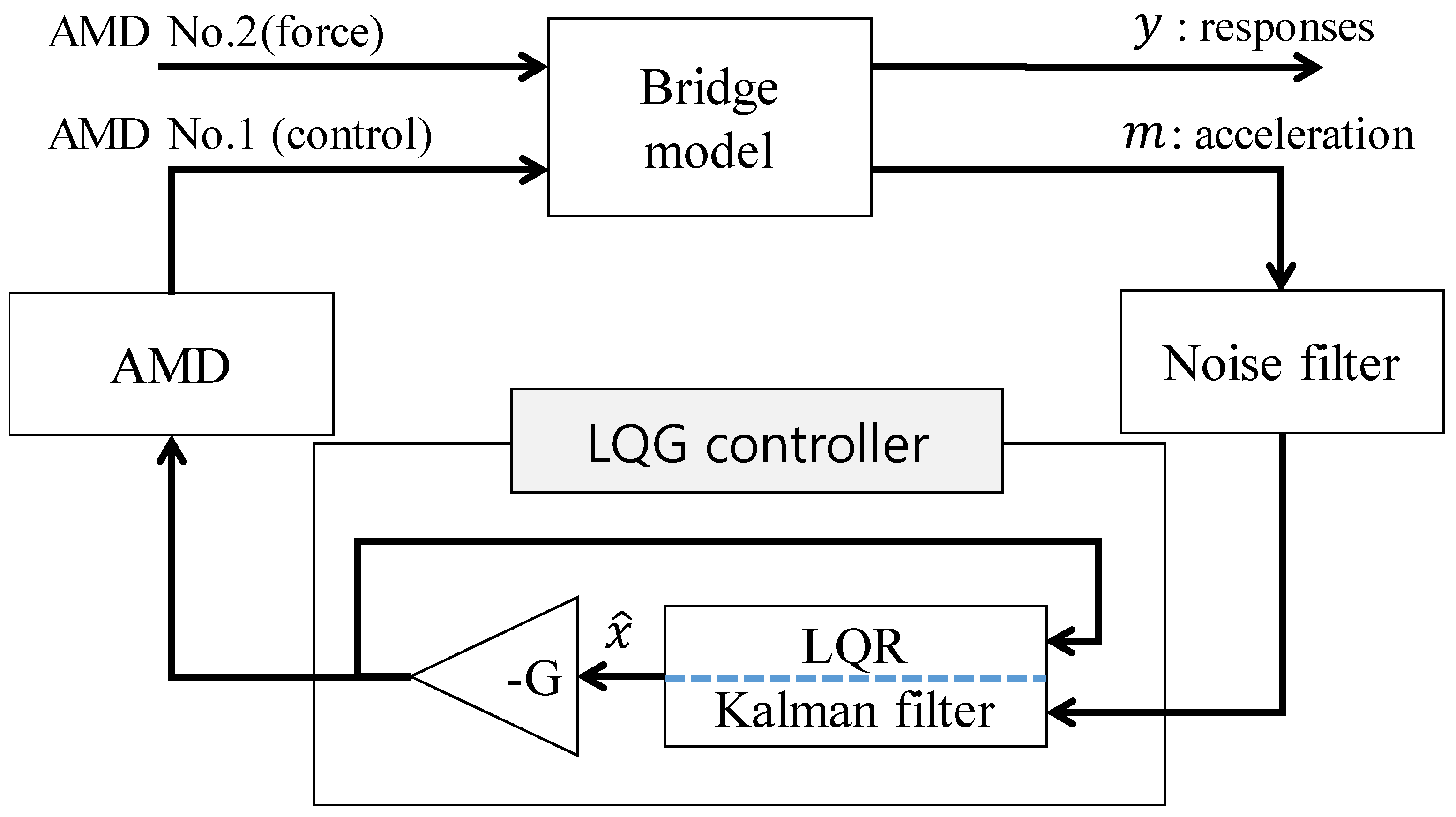
Figure 7 shows the block diagram for the entire system. The response (y) of the bridge model is generated by the external force, and the acceleration (m) is measured at the tip of the bridge model. This acceleration signal is input to the Kalman filter after the high-frequency noise signal is removed by the noise filter. The state vectors of the bridge model are estimated with the Kalman filter and multiplied by the control gain (G) to calculate the control signal. The moving mass of the AMD works up and down to reduce the vibration of the bridge model according to the control signal.
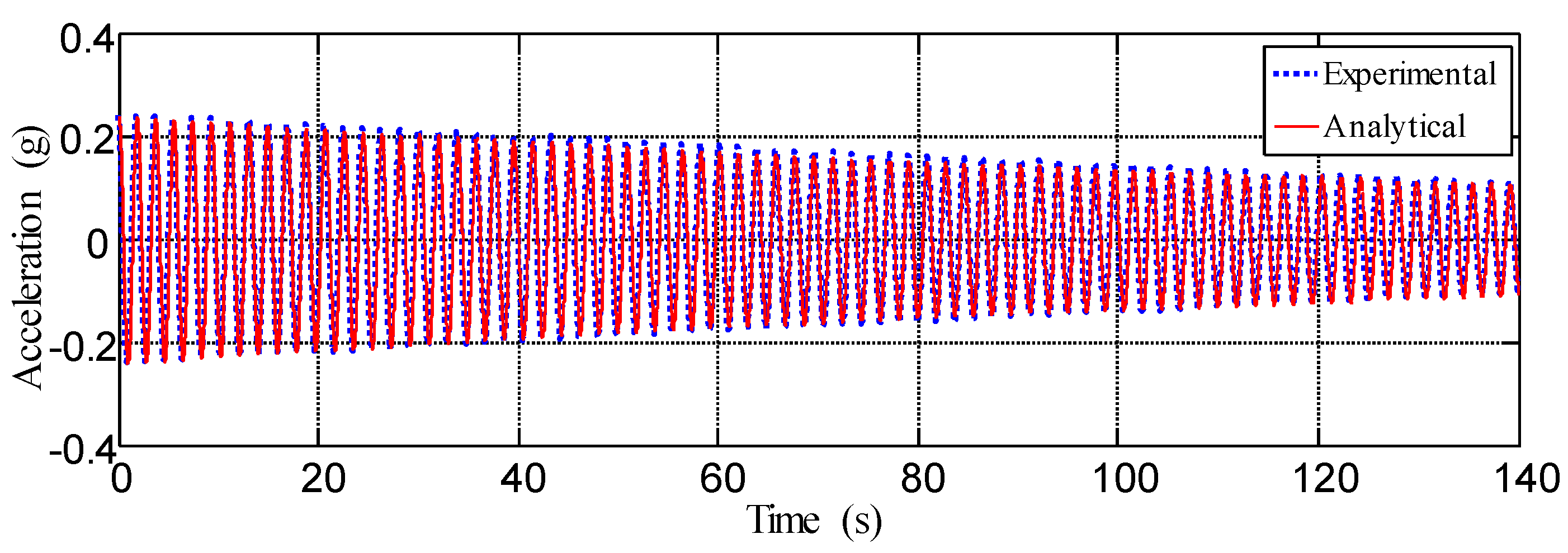
To design a controller consisting of the Kalman filter and LQR, each system needed to be identified. First, the bridge model was identified from its free vibration signal. Figure 8 shows the vibration acceleration data of the bridge model. Based on the measured data, the frequency and damping ratio of the bridge model were found to be 0.531 Hz and 0.17%, respectively. The measured and simulated accelerations of the bridge model were found to match closely.
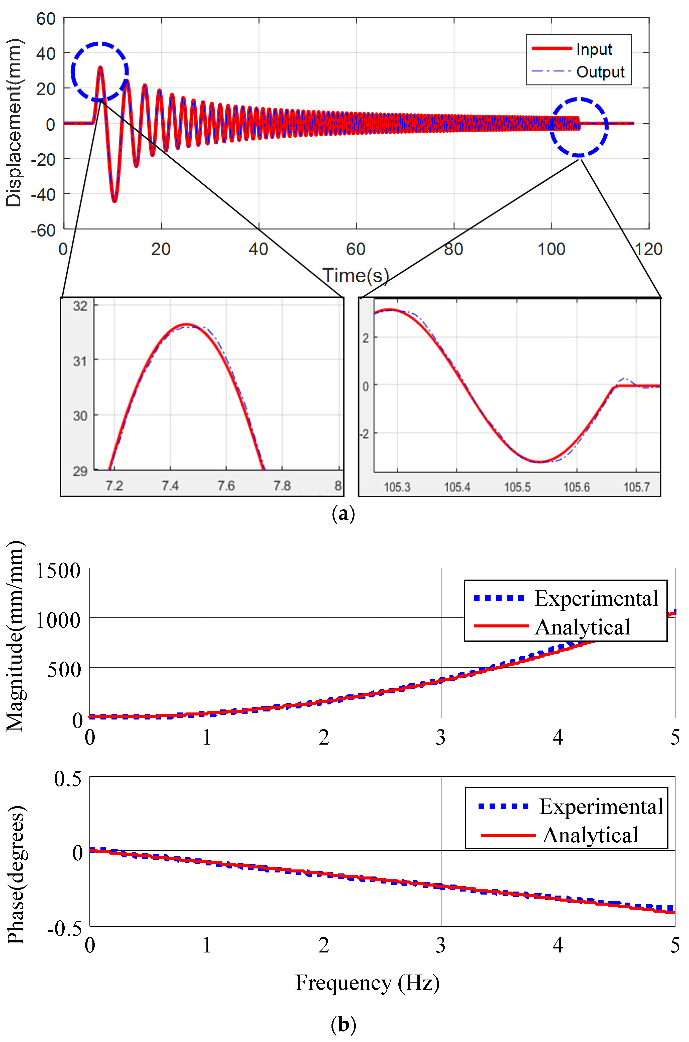
Second, sinusoidal sweep signals at 0.1–5 Hz were used to investigate the relationship (AMD dynamic model) between the input and the output of the AMD. The sinusoidal signal was defined as the input, and the measured displacement of the AMD moving mass was used as the output. Figure 9a shows the input and output signals (displacement) of the AMD. The transfer function of the two signals was based on MATLAB’s system identification toolbox and is shown in Figure 9b [36]; this function is given as
Third, the acceleration signal at the tip of the bridge model contains a high-frequency signal noise that must be removed. A second-order infinite impulse response (IIR) Butterworth filter was designed so that noise can only pass in the frequency range of 0.05–2 Hz. The designed noise filter is given by
4.3. Verification of the AMD Design and Control Performance
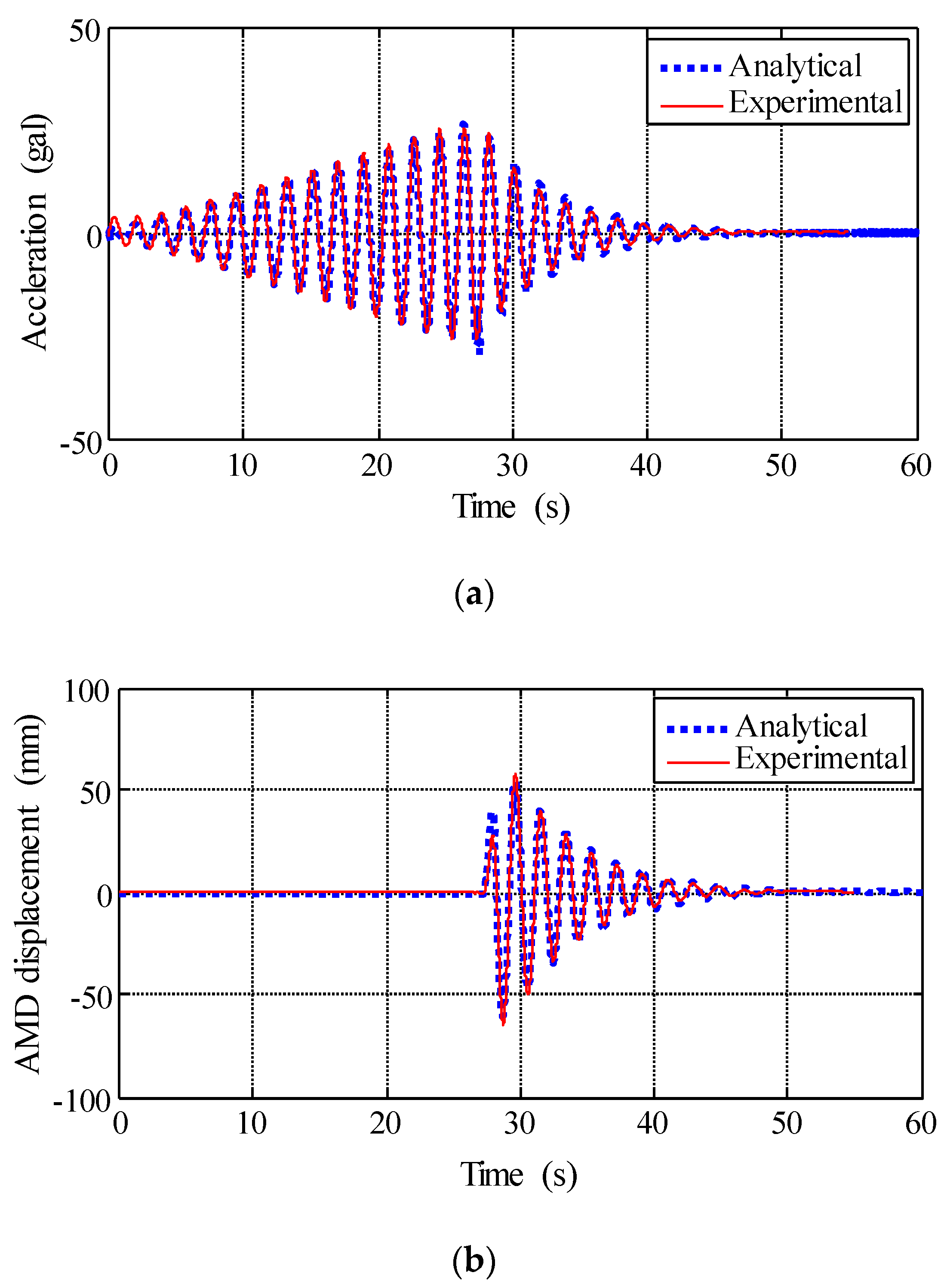
Experimental and numerical analyses were performed to verify the control performance of the LQG controller for the scaled-down bridge model. Generally, wind loads are divided into turbulence flow and laminar flow according to turbulence intensity. Since long bridges are mainly located in the sea, vortex vibration due to laminar flow may occur. In the case of this vortex vibration, since the vibration occurs at a frequency corresponding to the natural frequency of the bridge, this study generated this vibration using an exciter instead of wind in testing. The vibration of the girder caused by the wind load appeared as sinusoidal waves, and therefore, AMD No. 2 was used to simulate this vibration. Thus, AMD No. 2 was used as a vibrator to vibrate the bridge model to simulate wind loads, and AMD No. 1 was used to control the vibration of the bridge model. Figure 10 shows the simulation and experimental results for the bridge model and AMD. The bridge model was vibrated by AMD No. 2 for only 27 s, and AMD No. 1 operated after being stopped for 28 s. The blue dotted line represents the simulation results, and the red line represents the experimental results. The experimental behavior and analytically predicted results were almost identical, which verifies the validity of the designed LQG controller. The sampling time was 0.01 s in the experimental and numerical studies. Further, the time delay was not considered because of using the transfer function of AMD.
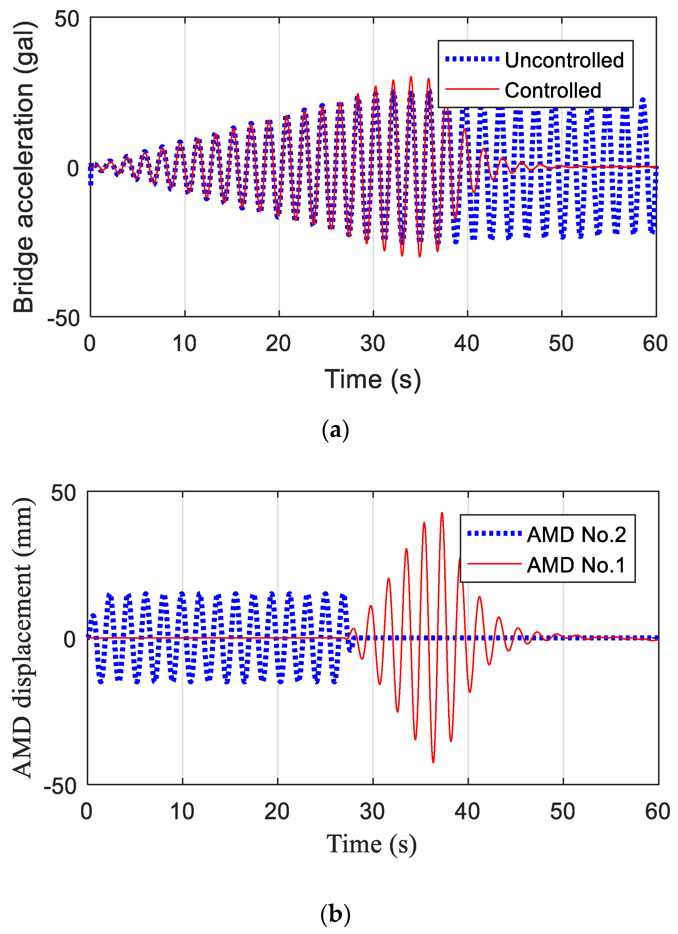
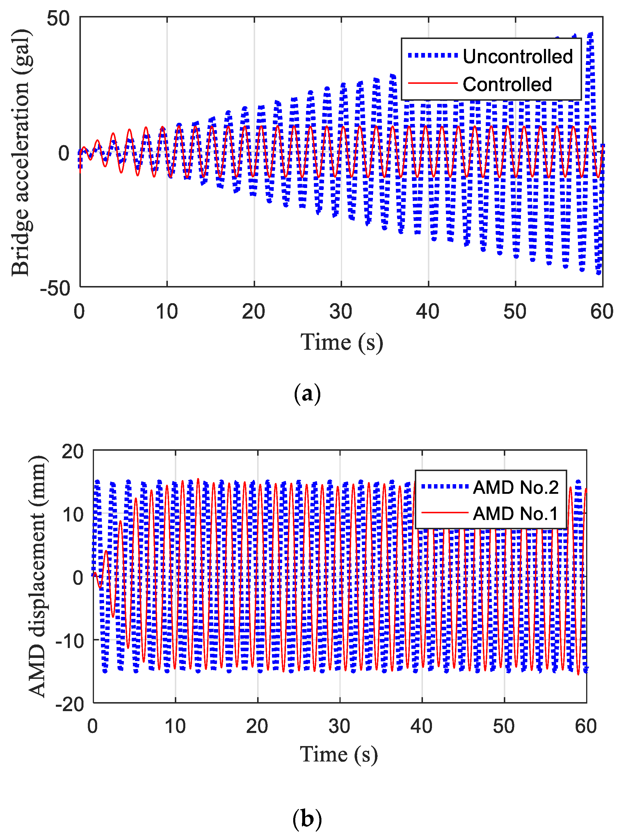
The proposed AMD was confirmed to effectively control the free vibration and harmonic load of the bridge model. Figure 11 shows the analysis results before and after control of the free vibration after excitation. Figure 11a shows the uncontrolled response to the excitation by AMD No. 2 (amplitude of 15 mm at 0.53 Hz for up to 27 s) and the controlled response with AMD No. 1. Figure 11b shows the displacements with the vibrating and controlling AMDs in operation. The blue line indicates the displacement when the model was excited with AMD No. 2 for 27 s, and the red line shows the displacement when the model was gradually controlled by AMD No. 1 after 27 s. AMD No. 1 did not immediately exert a large amount of control because a sudden control force could considerably affect the bridge model. This was performed using a rate limiter. The damping ratio was calculated by selecting only the free vibration section in Figure 11a and was found to increase from 0.17% to 9.2% when the model was controlled by AMD No. 1. Figure 12 shows the results before and after control with AMD No. 1 when the model was excited for 60 s with AMD No. 2. In Figure 12a, the blue line represents the uncontrolled acceleration of the bridge model, and the red line represents the controlled acceleration. When a sinusoidal force was induced by AMD No. 2, the amplitude of the bridge model did not increase by more than a certain amount despite the excitation from AMD No. 2. Figure 12b shows the displacement with AMD No. 2 as the vibrator and AMD No. 1 as the controller. When the model was excited at a frequency of 0.53 Hz and amplitude of 15 mm by AMD No. 2, the amplitude of AMD No. 1 was also maintained at 15 mm.
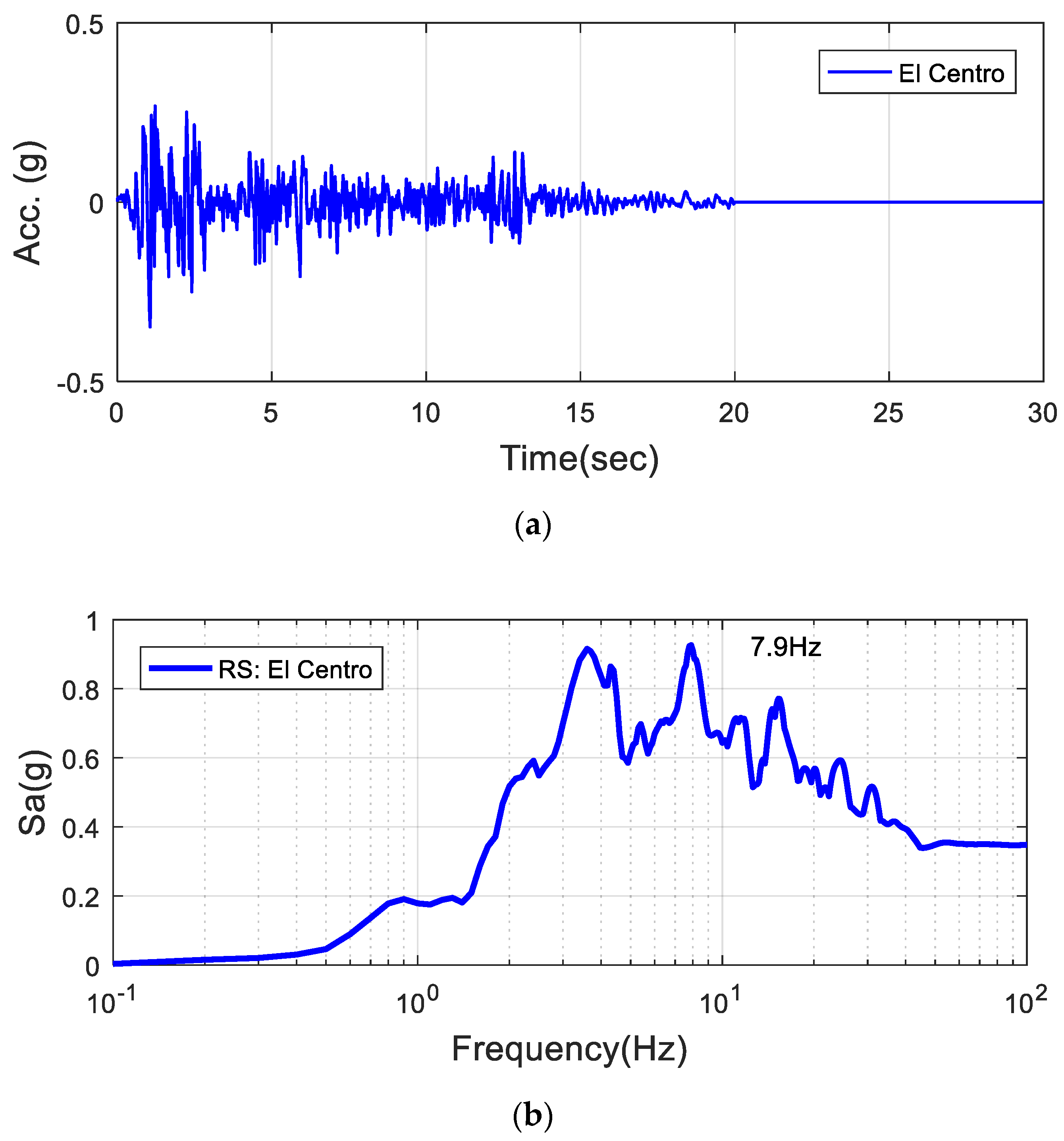
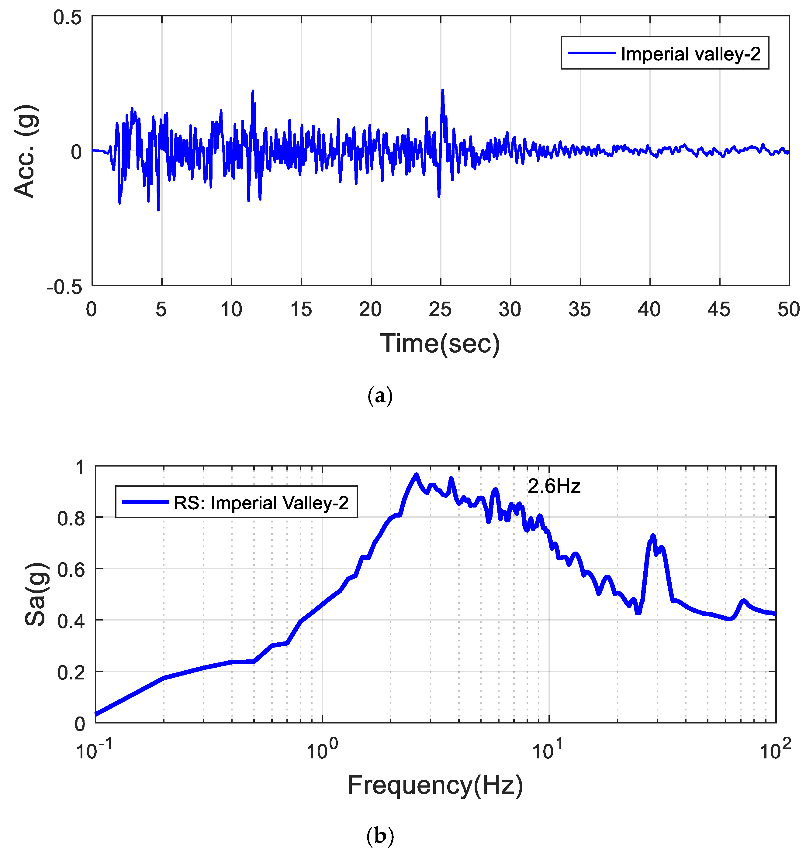
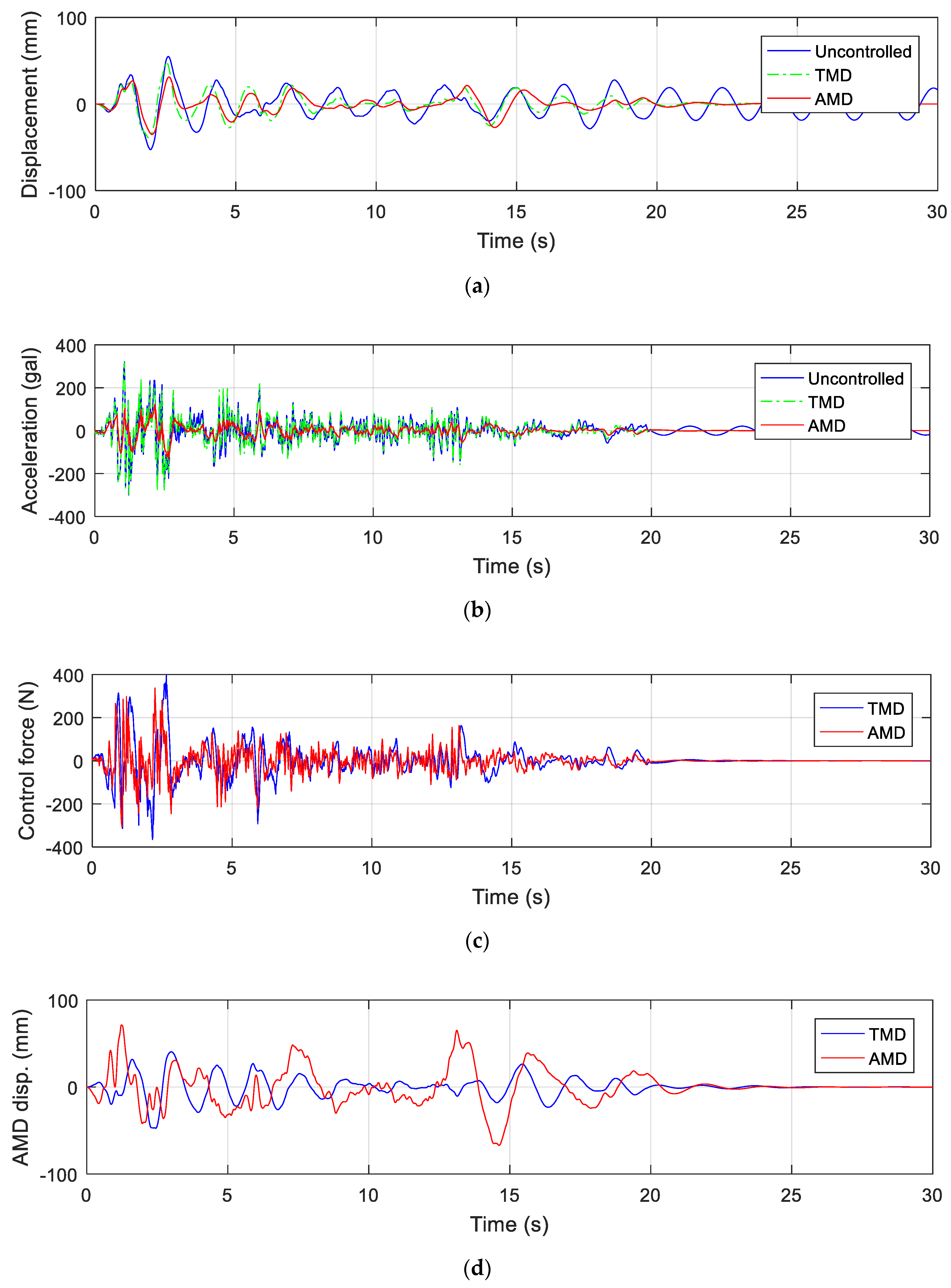
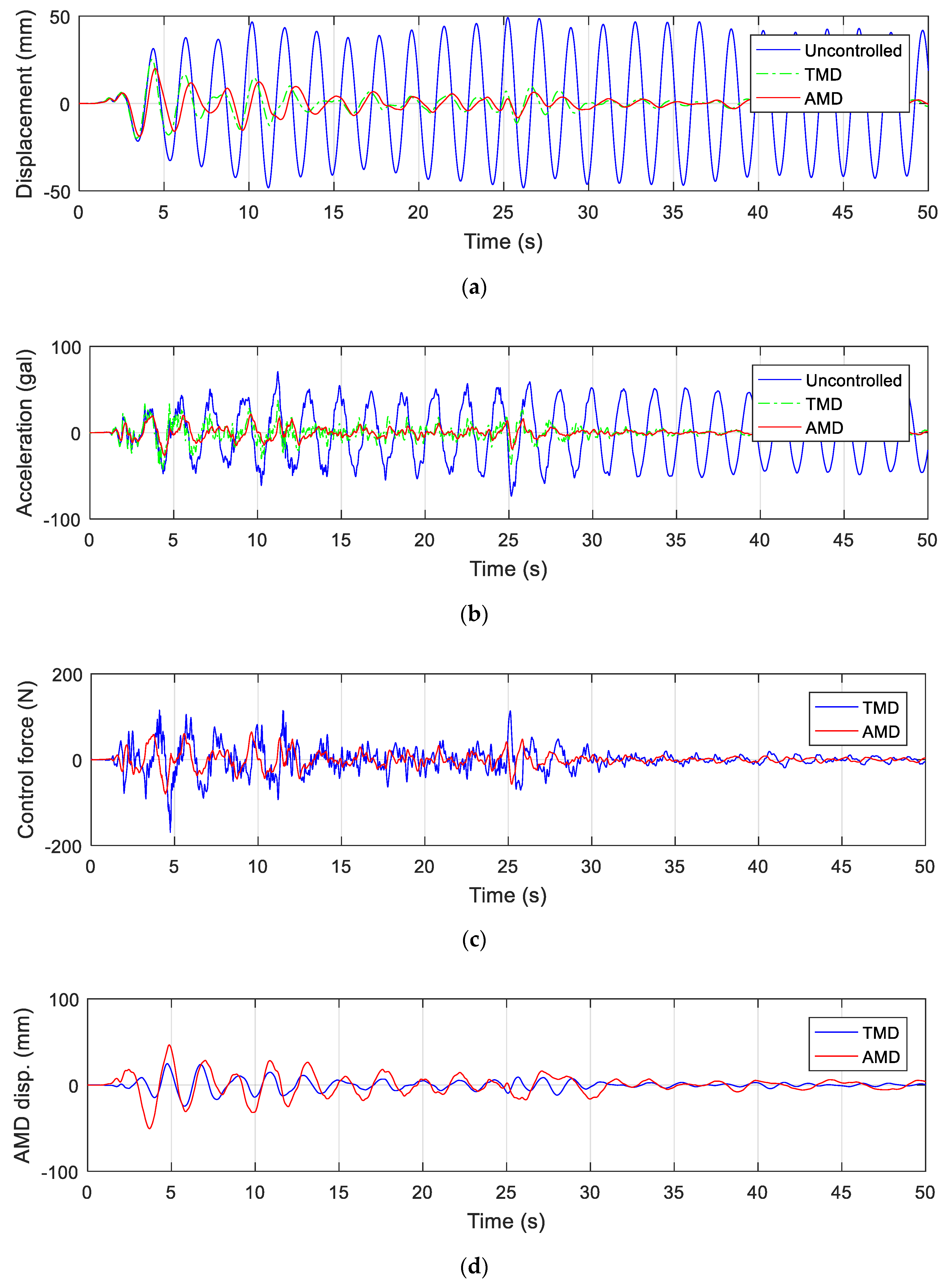
A numerical analysis was also performed on the vertical vibration control of a cable-stayed scaled bridge during an earthquake. The El Centro earthquake and Imperial Valley-2 earthquake were used for the earthquake simulation. Figure 13 and Figure 14 show the time history and response spectra of the El Centro and Imperial Valley-2 earthquakes, respectively. The number of AMDs was increased to six to simulate large loads such as earthquakes. To compare the vibration control performance of the AMD, a simulation was performed on the bridge with a TMD installed under both earthquakes. Figure 15 shows the simulation results for the bridge model with the El Centro earthquake using the AMD and TMD. In Figure 15a, the blue line represents the uncontrolled displacement of the bridge model, and the red line and green dot line represent the controlled displacement when the AMDs and TMD were in operation. Figure 15b shows the acceleration responses of the bridge model; Figure 15c, the control forces of the AMD and TMD; and Figure 15d, the displacement of the AMD and TMD when in operation. Figure 16 shows the analytical results for the bridge model with the Imperial Valley-2 earthquake. Similarly, Figure 16a,b shows the displacement and acceleration of the bridge model, respectively, and Figure 16c,d shows the displacements of the AMD and TMD, respectively. The acceleration and displacement of the bridge model for each earthquake are summarized in Table 4. The maximum displacement of the bridge model during the El Centro earthquake was 55 mm, which was reduced by 36% to 35 mm when the AMDs were in operation. The maximum acceleration was reduced by 59% from about 320 gal to 132 gal. With the Imperial Valley-02 earthquake, the maximum displacement of the bridge model decreased by 59% from 49 to 20 mm. The maximum acceleration was reduced by 63% from 73 to 26 gal. The decreasing rate of the maximum displacement and acceleration by TMD were 11.8% and 0.7% under the El Centro earthquake, respectively. The decreasing rate of the maximum displacement and acceleration by TMD were 57.1% and 51.6% under the Imperial Valley-2 earthquake, respectively. The TMD shows good vibration control performance only for the Imperial Valley-2 earthquake; however, the proposed AMD shows the excellent vibration control performance for both earthquakes. The vibration control performance of the AMD was confirmed for the cable-stayed bridge model through indoor experiments and analytical simulations. The results confirmed that the proposed AMD could sufficiently reduce the vertical vibration of a bridge subjected to wind and seismic loads.
5. Conclusions
In this study, an AMD was developed that uses a linear motor and coil spring, and the vibration control performance was experimentally and analytically investigated for excessive vertical vibrations that may affect a cable-stayed bridge. The following conclusions were drawn:
- The basic theory of LQG control, which combines an LQR and Kalman filter, was used to control the AMD.
- A scaled-down bridge model and AMD were fabricated, and the analytical responses of the bridge model and AMD agreed with the experimental results.
- When the bridge model was subjected to free vibration and a harmonic load, the proposed AMD rapidly reduced the vibration and significantly increased the damping ratio of the bridge from 0.17% to 9.2%.
- Numerical analysis showed that the proposed AMD reduced the acceleration of the bridge model by about 60% during the El Centro earthquake and the Imperial valley-02 earthquake;
- Moreover, in the case of the TMD, the vibration control performance was shown only for a special earthquake; however, the proposed AMD showed excellent vibration control performance for both earthquakes.
In this study, only the first vertical mode response was used for the vibration control of the scale-down bridge model. However, the control performance of the proposed AMD in response to various modes also needs to be considered in future research.
Funding
This study was conducted by research funds from Gwangju University in 2020.
Acknowledgments
This study was conducted by research funds from Gwangju University in 2020. The authors wish to thank Yun-Seok Kim and Seung-Woo Lee of TESolution (engineering company specializing in wind engineering and vibration control in Korea) for their contribution in this project.
Conflicts of Interest
The author declares no conflict of interest.
References
- Haque, M.N.; Katsuchi, H.; Yamada, H.; Nishio, M. Investigation of edge fairing shaping effects on aerodynamic response of long-span bridge deck by unsteady RANS. Arch. Civ. Mech. Eng. 2016, 16, 888–900. [Google Scholar] [CrossRef]
- Omenzetter, P.; Wilde, K.; Fujino, Y. Suppression of wind-induced instabilities of a long span bridge by a passive deck-flaps control system: Part I: Formulation. J. Wind Eng. Ind. Aerodyn. 2000, 87, 61–79. [Google Scholar] [CrossRef]
- Den Hartog, J.P. Mechanical Vibrations, 4th ed.; McGraw-Hill: New York, NY, USA, 1956. [Google Scholar]
- Chang, S.; Sun, W.; Cho, S.G.; Kim, D. Vibration control of nuclear power plant piping system using Stockbridge damper under earthquakes. Sci. Technol. Nucl. Install. 2016, 2016, 5014093. [Google Scholar] [CrossRef] [Green Version]
- Rahman, M.S.; Chang, S.; Kim, D. Multiple wall dampers for multi-mode vibration control of building structures under earthquake excitation. Struct. Eng. Mech. 2017, 63, 537–549. [Google Scholar]
- Cho, S.G.; Chang, S.; Sung, D. Application of tuned mass damper to mitigation of the seismic responses of electrical equipment in nuclear power plants. Energies 2020, 13, 427. [Google Scholar] [CrossRef] [Green Version]
- Meng, F.; Wan, J.; Xia, Y.; Ma, Y.; Yu, J. A multi-degree of freedom tuned mass damper design for vibration mitigation of a suspension bridge. Appl. Sci. 2020, 10, 457. [Google Scholar] [CrossRef] [Green Version]
- Gu, M.; Xiang, H.F.; Chen, A.R. A practical method of passive TMD for suppressing wind-induced vertical buffeting of long-span cable-stayed bridges and its application. J. Wind Eng. Ind. Aerodyn. 1994, 51, 203–213. [Google Scholar] [CrossRef]
- Xing, C.; Wang, H.; Li, A.; Xu, Y. Study on wind-induced vibration control of a long-span cable-stayed bridge using TMD-type counterweight. J. Bridge Eng. 2014, 19, 141–148. [Google Scholar] [CrossRef]
- Domaneschi, M.; Martinelli, L.; Po, E. Control of wind buffeting vibrations in a suspension bridge by TMD: Hybridization and robustness issues. Comput. Struct. 2015, 155, 3–17. [Google Scholar] [CrossRef]
- Wang, W.; Wang, X.; Hua, X.; Song, G.; Chen, Z. Vibration control of vortex-induced vibrations of a bridge deck by a singleside pounding tuned mass damper. Eng. Struct. 2018, 173, 61–75. [Google Scholar] [CrossRef]
- Pourzeynali, S.; Bahar, A.; Pourzeynali, S. Vertical vibration control of suspension bridges subjected to earthquake by semi-active MR dampers. Sci. Iran. 2017, 24, 439–451. [Google Scholar] [CrossRef] [Green Version]
- Fiebig, W. Reduction of vibrations of pedestrian bridges using tuned mass dampers (TMD). Arch. Acoust. 2010, 34, 165–174. [Google Scholar] [CrossRef] [Green Version]
- Debnath, N.; Duttab, A.; Deb, S.K. Multi-modal passive-vibration control of bridges under general loading-condition. Procedia Eng. 2016, 144, 264–273. [Google Scholar] [CrossRef] [Green Version]
- Yin, X.; Song, G.; Liu, Y. Vibration suppression of wind/traffic/bridge coupled system using multiple pounding tuned mass dampers. Sensors 2019, 19, 1133. [Google Scholar] [CrossRef] [PubMed] [Green Version]
- Chen, Z.; Fang, H.; Han, Z.; Sun, S. Influence of bridge-based designed TMD on running trains. J. Vib. Control 2019, 25, 182–193. [Google Scholar] [CrossRef]
- Nugroho, W.O.; Widarda, D.R.; Dwyana, O.H. Analysis study the used of tuned mass damper (TMD) on an existing train bridge due to high speed train with moving mass load approach. MATEC Web Conf. 2019, 258, 05005. [Google Scholar] [CrossRef]
- El Ouni, M.H.; Kahla, N.B.; Preumont, A. Numerical and experimental dynamic analysis and control of a cable stayed bridge under parametric excitation. Eng. Struct. 2012, 45, 244–256. [Google Scholar] [CrossRef]
- El Ouni, M.H.; Kahla, N.B. Numerical study of the active tendon control of a cable-stayed bridge in a construction phase. Shock. Vib. 2014, 2014, 937541. [Google Scholar] [CrossRef]
- Crusells-Girona, M.; Aparicio, A.C. Active control implementation in cable-stayed bridges for quasi-static loading patterns. Eng. Struct. 2016, 118, 394–406. [Google Scholar] [CrossRef] [Green Version]
- Soneji, B.B.; Jangid, R.S. Seismic control of cable-stayed bridge using semi-active hybrid system. Bridge Struct. 2006, 2, 45–60. [Google Scholar] [CrossRef]
- Ok, S.Y.; Kim, D.S.; Park, K.S.; Koh, H.M. Semi-active fuzzy control of cable-stayed bridges using magneto-rheological dampers. Eng. Struct. 2007, 29, 776–788. [Google Scholar] [CrossRef]
- Soto, M.G.; Adeli, H. Semi-active vibration control of smart isolated highway bridge structures using replicator dynamics. Eng. Struct. 2019, 186, 536–552. [Google Scholar] [CrossRef]
- Soares, R.W.; Barroso, L.R.; Al-Fahdawi, O.A.S. Response attenuation of cable-stayed bridge subjected to central US earthquakes using neuro-fuzzy and simple adaptive control. Eng. Struct. 2000, 203, 109874. [Google Scholar] [CrossRef]
- Scheller, J.; Starossek, U. A Versatile Active Mass Damper for Structural Vibration Control. In Proceedings of the 8th International Conference on Structural Dynamics, Leuven, Belgium, 4–6 July 2011. [Google Scholar]
- Zhang, Y.; Lia, L.; Zhang, X. Switch control of twin rotor damper for bridge vibration mitigation under different excitations. Procedia Eng. 2017, 199, 1707–1712. [Google Scholar] [CrossRef]
- Goorts, K.; Ashasi-Sorkhabi, A.; Narasimhan, S. Deployable active mass dampers for vibration mitigation in lightweight bridges. J. Struct. Eng. 2017, 143, 04017159. [Google Scholar] [CrossRef]
- Setio, H.D.; Gunawan, A.S. Numerical study of active mass damper application on cable-stayed bridge structure using artificial neural network algorithm. Int. J. Civ. Environ. Eng. 2017, 17, 1–17. [Google Scholar]
- Lu, L.T.; Chiang, W.L.; Tang, J.P. LQG/LTR control methodology in active structural control. J. Eng. Mech. 1998, 124, 446–454. [Google Scholar] [CrossRef]
- Lee, M.H. Active vibration control of smart structural system using a novel control approach. J. Vibroeng. 2013, 15, 845–855. [Google Scholar]
- Koszewnik, A. The Active Vibration Control of the Plate Structure by Using LQG Controller and Piezo-Stripes. In Proceedings of the 2017 22nd International Conference on Methods and Models in Automation and Robotics (MMAR), Międzyzdroje, Poland, 28–31 August 2017; pp. 797–802. [Google Scholar]
- Rosoł, M.; Martynowicz, P. Implementation of the LQG controller for a wind turbine tower-nacelle model with an mr tuned vibration absorber. J. Theor. App. Mech. 2016, 54, 1109–1123. [Google Scholar] [CrossRef]
- Islam, M.; Jahra, F.; Hiscock, S. Data analysis methodologies for hydrodynamic experiments in waves. J. Nav. Archit. Mar. Eng. 2016, 13, 1–15. [Google Scholar] [CrossRef] [Green Version]
- Preumont, A. Twelve Lectures on Structural Dynamics; Springer: Berlin/Heidelberg, Germany, 2013. [Google Scholar]
- Lindgren, E.R. The generalized energy method for the formulation of the equations of motion in classical mechanics. Phys. Scr. 2002, 66, 114–124. [Google Scholar] [CrossRef]
- Ljung, L. MATLAB System Identification Toolbox User’s Guide; MathWorks: Natick, MA, USA, 2014. [Google Scholar]
Figure 1.
Block diagram of the linear quadratic Gaussian (LQG) control system.

Figure 2.
Geometry of the target cable-stayed bridge (unit: mm).

Figure 3.
(a) Finite element model and (b) target mode shape (first vertical mode).

Figure 4.
(a) Active mass damper (AMD) and scaled-down bridge model and (b) section of the scaled-bridge model.
Figure 4.
(a) Active mass damper (AMD) and scaled-down bridge model and (b) section of the scaled-bridge model.

Figure 5.
AMD assembly: (a) AMD spring, (b) AMD frame, (c) linear motor, and (d) AMD.

Figure 6.
Block diagram of the entire system.

Figure 7.
Block diagram of the whole system.

Figure 8.
Free vibration signal for system identification of the bridge model.

Figure 9.
(a) AMD input/output and (b) transfer function.

Figure 10.
Comparison of experimental and analytical results: (a) acceleration of the bridge model and (b) displacement of the moving mass of AMD No. 1.
Figure 10.
Comparison of experimental and analytical results: (a) acceleration of the bridge model and (b) displacement of the moving mass of AMD No. 1.

Figure 11.
Control results for free vibration after excitation through simulation: (a) acceleration of the bridge model and (b) displacement of the vibrator and AMD.
Figure 11.
Control results for free vibration after excitation through simulation: (a) acceleration of the bridge model and (b) displacement of the vibrator and AMD.

Figure 12.
Control results for a constant external force through simulation: (a) acceleration of the bridge model and (b) displacement of the vibrator and AMD.
Figure 12.
Control results for a constant external force through simulation: (a) acceleration of the bridge model and (b) displacement of the vibrator and AMD.

Figure 13.
El Centro earthquake: (a) time history and (b) response spectrum.

Figure 14.
Imperial valley-2 earthquake: (a) time history and (b) response spectrum.

Figure 15.
Analytical results with the El Centro earthquake: (a) bridge displacement, (b) bridge acceleration, (c) AMD force, and (d) AMD displacement.
Figure 15.
Analytical results with the El Centro earthquake: (a) bridge displacement, (b) bridge acceleration, (c) AMD force, and (d) AMD displacement.

Figure 16.
Analytical results with the Imperial valley-2 earthquake: (a) bridge displacement, (b) bridge acceleration, (c) AMD force, and (d) AMD displacement.
Figure 16.
Analytical results with the Imperial valley-2 earthquake: (a) bridge displacement, (b) bridge acceleration, (c) AMD force, and (d) AMD displacement.


Table 1.
Specifications of actuator.
| Item | Value |
|---|---|
| Stroke (mm) | ±550 |
| Max control force (N) | 3600 |
| Frequency range (Hz) | 0.1 to 0.3 |
| Mass (kg) | 14,000 |
| Power (kw) | 11 |
Table 2.
Mass and frequency of the scale bridge model.
| Item | Prototype | Scaled Model |
|---|---|---|
| Mass (ton) | 1526 | 1.509 |
| Frequency (Hz) | 0.170 | 0.542 |
Table 3.
Specifications of the AMD.
| Item | Value |
|---|---|
| Moving mass (kg) | 50 |
| Stroke (mm) | ±70 |
| Force (N) | 38.8 |
Table 4.
Analytical results for the bridge model with each earthquake.
| El Centro | Imperial Valley-02 | ||||
|---|---|---|---|---|---|
| Displacement (mm) | Acceleration (gal) | Displacement (mm) | Acceleration (gal) | ||
| AMD | Uncontrolled | 54.9 | 320.5 | 49.1 | 73.5 |
| Controlled | 35.1 | 132.0 | 19.9 | 26.7 | |
| Decreasing rate | 36.1% | 58.8% | 59.4% | 63.7% | |
| TMD | Uncontrolled | 54.9 | 320.5 | 49.1 | 73.5 |
| Controlled | 48.4 | 318.3 | 21.1 | 35.6 | |
| Decreasing rate | 11.8% | 0.7% | 57.1% | 51.6 | |
© 2020 by the author. Licensee MDPI, Basel, Switzerland. This article is an open access article distributed under the terms and conditions of the Creative Commons Attribution (CC BY) license (http://creativecommons.org/licenses/by/4.0/).
Share and Cite
MDPI and ACS Style
Chang, S. Active Mass Damper for Reducing Wind and Earthquake Vibrations of a Long-Period Bridge. Actuators 2020, 9, 66. https://0-doi-org.brum.beds.ac.uk/10.3390/act9030066
AMA Style
Chang S. Active Mass Damper for Reducing Wind and Earthquake Vibrations of a Long-Period Bridge. Actuators. 2020; 9(3):66. https://0-doi-org.brum.beds.ac.uk/10.3390/act9030066
Chicago/Turabian StyleChang, Seongkyu. 2020. "Active Mass Damper for Reducing Wind and Earthquake Vibrations of a Long-Period Bridge" Actuators 9, no. 3: 66. https://0-doi-org.brum.beds.ac.uk/10.3390/act9030066
Note that from the first issue of 2016, this journal uses article numbers instead of page numbers. See further details here.