Pneumatically Actuated Thin Glass Microlens for On-Chip Multi-Magnification Observations


1
Laboratory for Integrated Biodevice Unit, Center for Biosystems Dynamics Research (BDR), RIKEN, Osaka 565-0871, Japan
2
Graduate School of Frontier Biosciences, Osaka University, Osaka 565-0871, Japan
3
Graduate School of Nara Institute of Science and Technology, Nara 630-0192, Japan
*
Authors to whom correspondence should be addressed.
Actuators 2020, 9(3), 73; https://0-doi-org.brum.beds.ac.uk/10.3390/act9030073
Submission received: 22 June 2020
/
Revised: 3 August 2020
/
Accepted: 21 August 2020
/
Published: 23 August 2020
(This article belongs to the Special Issue Microfluidics Actuators)
Abstract
:This paper presents a self-contained micro-optical system that is magnification-controlled by adjusting the positions of the microlens in the device via pneumatic air pressure. Unlike conventional dynamic microlenses made from a liquid or polydimethylsiloxane (PDMS) that change their shapes via external actuation, this system combines a fixed-curvature glass microlens, an inflatable PDMS layer, and the external pneumatic air pressure supply as an actuator. This device showed several advantages, including stable inflation, firm structure, and light weight; it achieved a larger displacement using the glass microlens structure than has been reported before. This fixed-curvature microlens was made from 120 µm-thick flat thin glass slides, and the system magnification was manipulated by the deflection of a 100 µm-thick PDMS layer to alter the distance from the microlens to the microfluidic channel. The system magnification power was proportional to the air pressure applied to the device, and with a 2.5 mbar air pressure supply, a 2.2X magnification was achieved. This optical system is ideal for combining with high resolving power microscopy for various short working distance observation tasks, and it is especially beneficial for various chip-based analyses.
1. Introduction
Optical systems at any scale require a focalizing mechanism [1] to produce clear and magnified images, as in cameras [2] or endoscopes [3]. To accurately observe a target, different magnification adjustments are necessary, and the system magnifications are determined by two key elements: the optical lens and the actuation method.
Microlenses are an important optical component that are often implemented in a miniaturized optical system for various purposes. These microlenses can roughly be categorized into two types. The first type is the fixed-curvature “solid” microlens [4] made from glass materials [5,6], and its magnification adjustment is achieved by changing the distance between one or more coupled lenses in the system [7]. Although fixed-curvature glass microlenses produce relatively stable and good quality images compared to microlenses made from other materials, its fabricating limitations and actuating methods for moving those “solid” lenses in the applications remain just as problematic. The second type is a “soft” microlens that is made from a liquid [8] or polydimethylsiloxane (PDMS) [9]. Its magnification adjustment is achieved either by changing the lens geometric curvature by external actuation [10], or by modifying the refractive index distribution inside of the lens materials [11,12], but many factors such as transparency, microlens size, and curvature deformability [13] affect the soft microlens performance in applications.
Several actuation methods have been introduced to control magnification of optical systems, such as piezoelectric actuation [14], electro-wetting deformation [15], electromagnetic actuation [16], and thermoelectrical actuation [17]. However, most of these actuation methods are structurally complex and large-scale, and they give unstable optical performance. Particularly, these magnification adjustment processes are time-consuming and need multiple objective lens combinations in their systems, which makes it difficult to observe a flowing target in a microfluidic channel in various lab-on-chip applications [18]. Therefore, simple and practical observation methods that offer on-chip multiple magnification functions with simple operating procedures, reliable optical performance, an efficient actuation manner, and that are compatible with other miniaturized devices are in strong demand.
In this paper, we demonstrate a self-contained pneumatically actuated optical system that had its magnification controlled by the deflection of a 100 µm-thick PDMS layer. A fixed-curvature thin glass microlens of 500 µm diameter was used in the device, and the microlens position was altered by changing the distance from the microlens to the target by applying different pneumatic air pressures to the deformable PDMS chamber. The PDMS layer was used as a moving part in the device; PDMS is a widely used material for fabricating pressure displacement devices [19], valves, and pumps [20], due to its good pressure sensitivity, easy fabrication, and cost-efficient advantages. However, most importantly, PDMS is easy to handle and it is not fragile as thin glass layers [21,22,23,24].
A glass microlens was implemented for the device because it possesses many optical merits [25], such as excellent transparency in the visible wavelength range, low surface roughness, good temperature stability, and good solvent resistance. It was challenging to fabricate the extremely small diameters (<1 mm) of the glass optic lens. We have previously reported a microlens fabrication method [26,27] using ultra-thin glass slides with different thickness from 30 to 240 µm, and we have successfully fabricated microlenses with diameters from 30 to 3.5 mm. The fabricated microlens magnification power depends on the inflated curvature of the lens. The curvature formation can be controlled by modifying the diameters of the microlens, the thickness of the glass slide, and the etching depths of the microcavities on the substrate. The microlens fabrication flexibility and other advantages inspired us to further develop a miniaturized on-chip observation method by employing this type of “solid” microlens. To better illustrate the magnification capability and easy handling reasons, we used a 500 µm diameter thin glass microlens for the demonstration. Additional information on the microlens magnification power with the size difference comparison is given in the supplementary information as Figure S1 and Graph S1.
2. Materials and Methods
2.1. The Adjustable Magnification Optical System
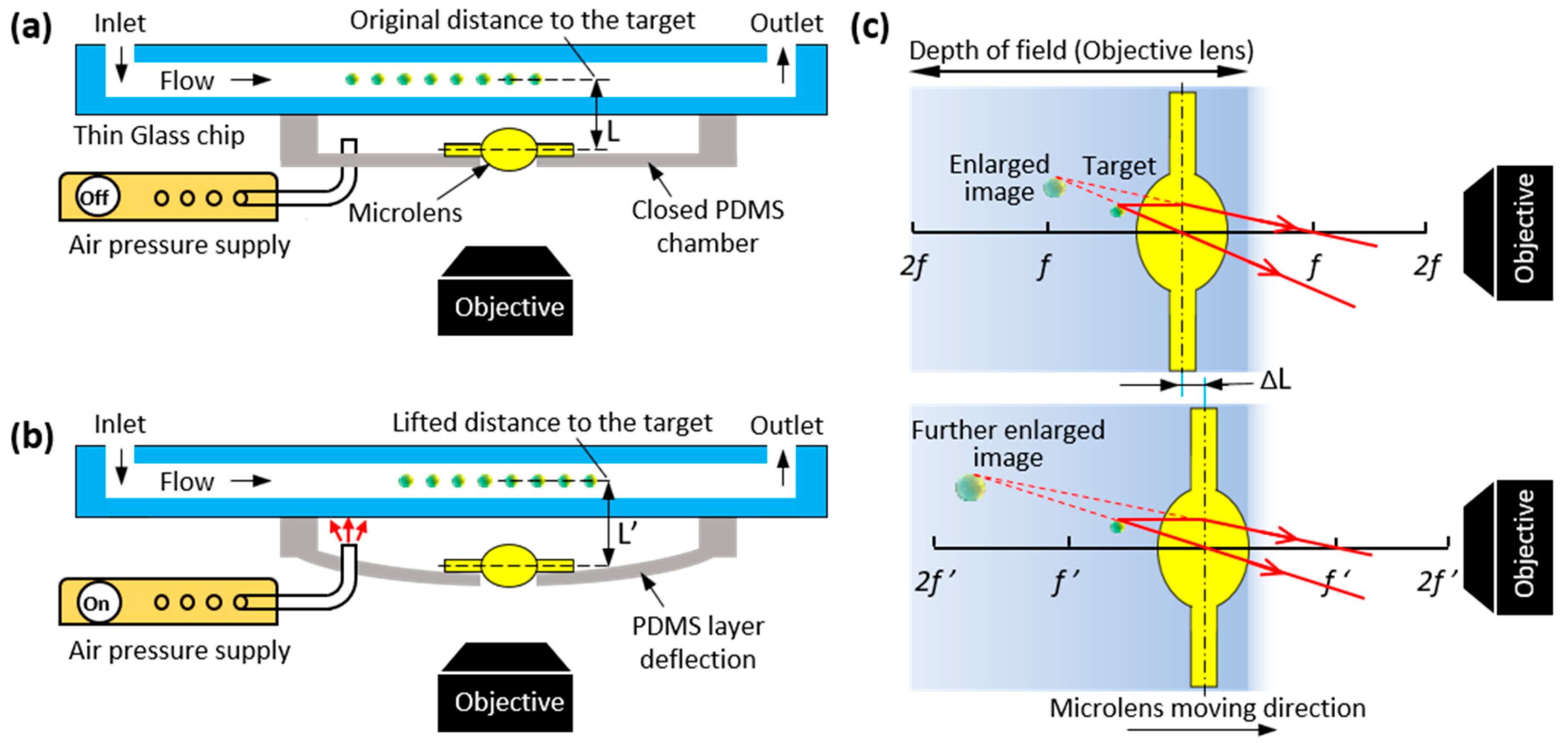
The conceptual image of the pneumatically controlled optical system using a thin glass microlens to observe a microchannel at various magnifications is shown in Figure 1. A deformable closed PDMS chamber with the microlens is plasma bonded to the microfluidic glass chip. By regulating the external pneumatic air pressures to control the deflections of the thin elastic PDMS layer and the distance between the microlens and glass chip, an on-chip observation system providing various magnifications can be achieved. The microlens positions changes before and after the air pressure is applied, as shown in Figure 1a,b.
In optics, the lens position is critical in producing the desired quality of sharp and magnified images. The depth of focus is a unique characteristic of an optical lens and the ability of maintaining the focus at different positions in the system [28]. In other words, within a certain area, the microlens is capable of producing acceptably sharp, clear, and variously magnified images without changing the positions of microscope objectives and the target, and only altering the microlens position in the system. However, once the altered distance is out of the limit, the image will show obvious distortion and blurring. Figure 1c shows the microlens imaging principle in this actuator system. In this method, the target is placed before the focus point of the proposed convex lens, as shown in the Figure 1c upper image, then a virtual enlarged view of the target is formed. Since this enlarged virtual image is formed in the area of objective lens’ depth of field, without tuning the distance between the objective lens and target, a magnified image of the target is achieved. Then, by altering the distance between the target and the microlens, as shown in the Figure 1c bottom image, the further enlargement of the image of the target is achievable. Based on this theory, an observing method for flowing targets inside the microchannel at various magnifications under different air pressures is feasible.
In the demonstration, fluorescent polystyrene latex beads (diameter, 10 μm) (Polysciences, Inc., Warrington, PA, USA) flowed inside the microchannel. A fabricated 500 μm diameter thin glass microlens was filled with mineral oil (SMR-100; Miyazaki, Japan) to enhance the optical power of the microlens. A syringe pump (Fusion-400; Chemyx, Stafford, TX, USA) was used to introduce microflow into the microchannel. The microscopes that were used in the experiments included: a digital microscope (VHX-1000, Keyence, Osaka, Japan), a measuring microscope (MF-B1010C; Mitutoyo, Tokyo, Japan) with an objective 10 × lens (NA, 0.28), and a fluorescence microscope (IX-71; Olympus, Tokyo, Japan) with an objective 1.6 × lens (NA, 0.08) with excitation/emission wavelengths of 480/520 nm. All of the observed images were captured with commercial interface software (cellSens; Olympus).
2.2. Thin Glass Microlens Preparation
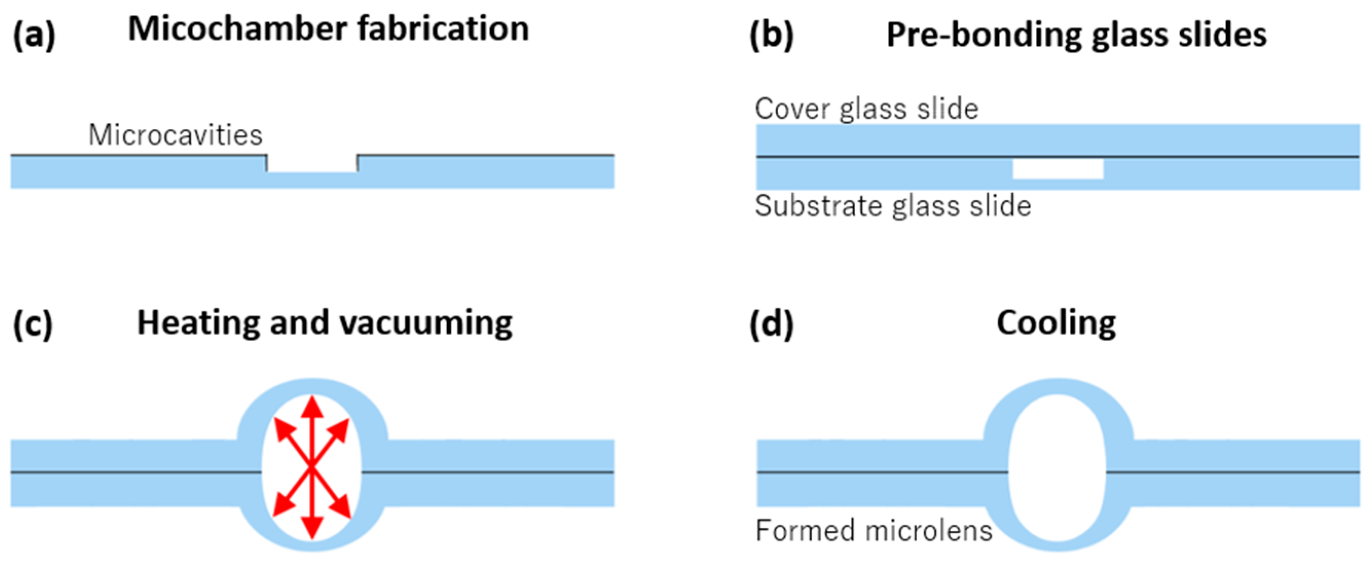
The glass microlens used for this demonstration was fabricated from borosilicate thin glass slides (30 mm × 70 mm with 0.12 mm thickness). Details of the fabrication procedures and thermal conditions can be found in our previous paper [26]. Here, we just briefly describe the main steps, as summarized in Figure 2. First, after annealing the glass slide, metal layers of chromium (Cr) and gold (Au) were separately sputtered onto the slide. The microlens structure was obtained and the microcavities were wet-etched on one of the glass slides, as shown in Figure 2a. Second, the substrate and cover glass slides were immersed in piranha solution, and then the two slides were pre-bonded by gently pressing on them, while keeping the microcavities between two glass slides (Figure 2b). Third, the pre-bonded glass slides were placed in a programmable furnace and heated for fusion bonding under a vacuum condition (Figure 2c). Finally, under the proper cooling process, a permanently shaped thin glass microlens was obtained (Figure 2d).
2.3. The PDMS Layer Thickness Verification
Confirming the thickness of the PDMS layer that is deflected in different pneumatic air pressures is important because it will determine the sensitivity of the system. If it is too thick, the actuation system will require larger air pressures to shift the microlens, and that will increase the pressure experienced by the device, affecting the closed chamber sealing and inducing pressure leakages. If it is too thin, the deflection is difficult to control and the PDMS layer rigidity is lost. We compared PDMS layers of 100 µm and 500 µm thicknesses. The results showed that the 100 µm-thick PDMS layer was more suitable when the above factors were considered. Thus, we primarily decided to use the 100 µm-thick PDMS layer for the device.
2.4. The PDMS Chamber Inflation Investigation
To investigate the 100 μm-thick PDMS layer deflections for various pneumatic air pressures, we set up a laser deviation measuring system, as shown in Figure 3. We fabricated a PDMS chamber by cutting out a 20 × 20 mm square hole in the center on a 500 μm-thick PDMS layer as the air chamber. Then, we plasma bonded the chamber and the cover part of the 100 μm-thick PDMS layer to a substrate glass chip, on which an oil-filled microlens had been previously stuck via a strong adhesive to the thin PDMS layer, as shown in enlarged image A of Figure 3. Then, using a common biopsy punch we made a 500 μm-diameter orifice through which to make a connection to the microfluidic air flow supplier (MFCS-4C; Fluigent, Inc., Sarasota, FL, USA), using a MAESFLO software controlling interface.
This experiment required a flat glass chip substrate (30 × 70 × 0.7 mm thickness) and a cylindrical laser tube that provided a green helium-neon laser at 543.5 nm wavelength (05-LGP-193; Melles Griot, CA, USA). Before applying air pressures, we calibrated the radiated laser beam focus that was refracted by the microlens on the detection sensor using an optic lens. When there is no air pressure applied, the laser spot remains stable and locates on the light detector (Purple dot in Figure 3). However, when the air pressure applied into the closed chamber, the PDMS layer deflects the microlens original position and shifts the reflected laser spot (Red dot in Figure 3). The deviations of the focus light position were transferred into the voltage signal and measured by a digital storage oscilloscope (TDS2001C, Tektronix, Beaverton, OR, USA). The air pressure is manipulated by the MFCS-4C Fluigent microfluidics control system.
3. Results and Verification
3.1. Morphological and Optical Evaluations of the Thin Glass Microlens
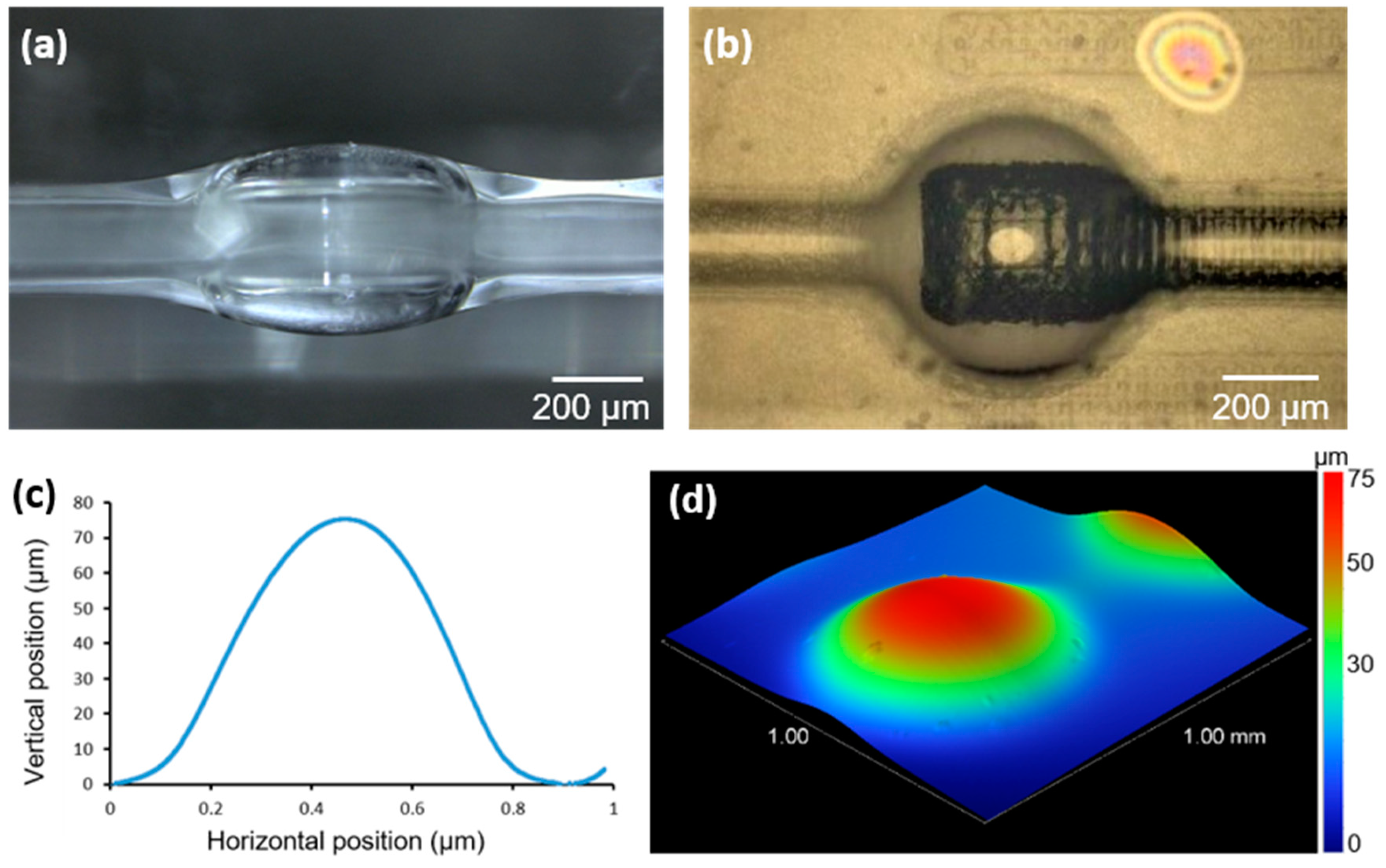
A microlens with a diameter of 500 μm was fabricated on a thin glass slide. We evaluated the microlens curvature heights, which on average reached approximately 75 μm. Because of this, the thin glass microlens originally was hollow, and we filled it with liquid oil through the microchannel that formed at the same time of wet etching on the substrate glass, as shown in Figure 4a,b. A comparison image of the single and arrays of the microlens that connected with the microchannel is given in supplementary information as Figure S2. We investigated the morphological assessment by measuring the surface property using a stylus profiler (DektakXT; Bruker Nano Surfaces, Tucson, AZ) at the measuring resolution of 0.1 μm, and the measured results are shown in Figure 4c,d. Then, we used a glass cutter to extract the microlens from the whole chip into suitable pieces and prepared it for insertion into the closed PDMS chamber.
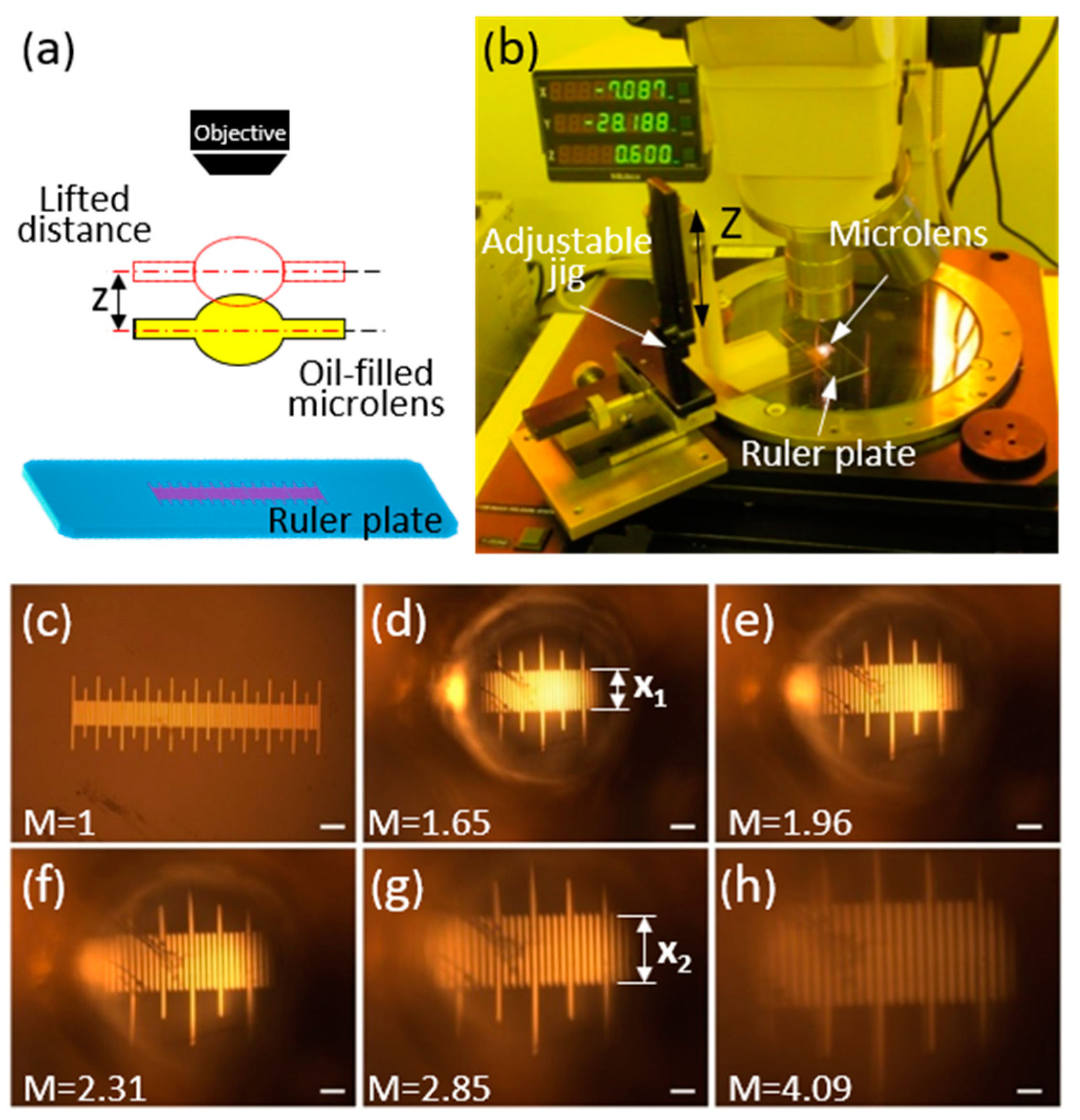
To investigate the optical performance of the fabricated 500 μm-thick oil-filled thin glass microlens, we conducted the following experiment, in which we expected to observe different magnified images of a glass micro-ruler plate by changing the distances between the microlens and the micro-ruler. The experiment concept is illustrated in Figure 5a, a photo of the actual setup is given in Figure 5b, and the results are shown in Figure 5c–h.
In the measurement, we first calibrated the focus on the micro-ruler plate (Figure 5c) to obtain the real dimensions of the micro-ruler without microlens magnification. Then, we calibrated the microscope’s focus through the microlens to the same micro-ruler by lowering the microscope focus to a distance of 95 μm, at which a clear image at 1.65 magnification was confirmed (Figure 5d); the magnified width of the scale bar was marked as X1. Figure 5e was obtained by lifting the microlens 100 μm from the micro-ruler plate, at the magnification of 1.96. By lifting another distance of 100 μm, an image at the magnification of 2.31 was obtained, as shown in Figure 5f. For the third lifting of 100 μm, an image magnification of 2.85 was obtained, but the image started to blur. The scale bar width was further magnified as X2. In the fourth test, we lifted the microlens another 100 μm, but we could not get a clear image. We recalibrated the microscope objective focus level by lowering the microscope (towards the ruler plate) by 79 μm, and achieved an image magnification of 4.09. Any further lifting or lowering of the microlens could not focus the image.
This experiment proved the functionality of the oil-filled microlens to produce different magnified images at different positions to the target. Other different diameters of microlenses magnifications were evaluated by the same method, and the measuring results are given in the supplementary information as Figure S3.
3.2. Closed PDMS Chamber Inflation Characterization
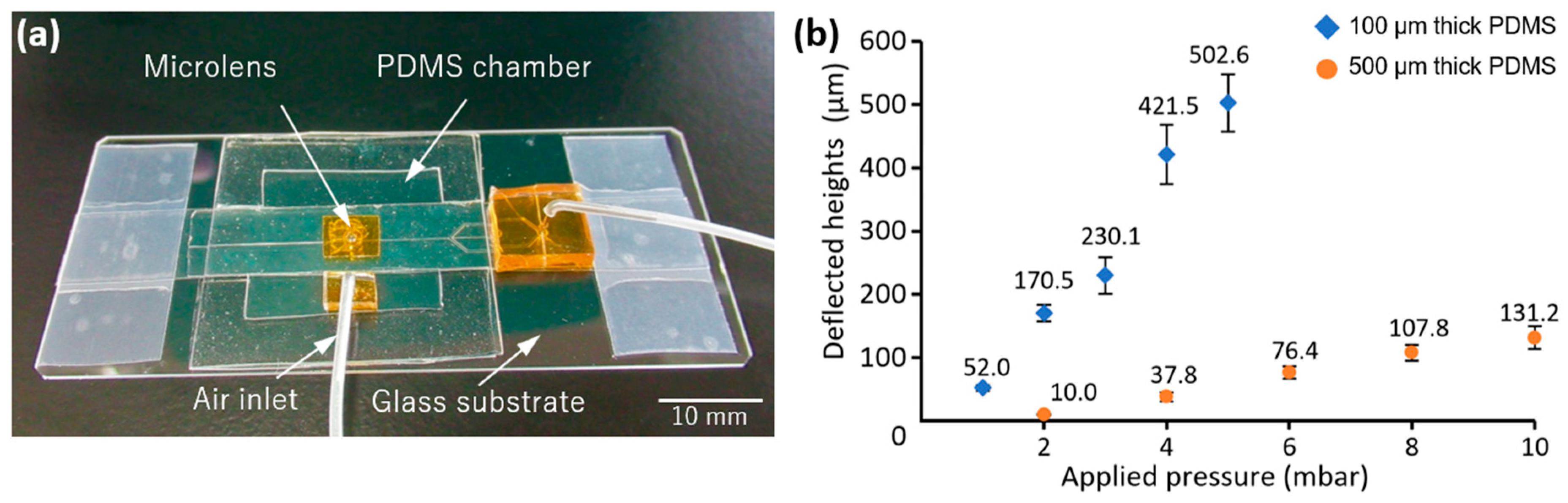
The thin PDMS layer inflation was measured using the laser beam method [29,30,31], which is commonly used for accurate displacement evaluations. The detector observed the reflected beam deviation from an aperture and the recorded values, which were then transferred to an oscilloscope as electrical voltage signals and screened. Two different thicknesses of PDMS layers, respectively at 100 μm and 500 μm, were measured. The obtained deflection result is shown in Figure 6b. The actual image of the fabricated device used in the measurement is shown in Figure 6a. Via the experiment, the PDMS chamber deflection responses to the various air pressures were characterized, which allowed us to regulate the microlens positions in the system by manipulating external pneumatic pressures. Considering the device stable functionality in the various pressures, we only used the 100 μm-thick PDMS layer for the remaining demonstration.
3.3. Demonstration of the On-Chip Optical System Performance at Various Magnifications
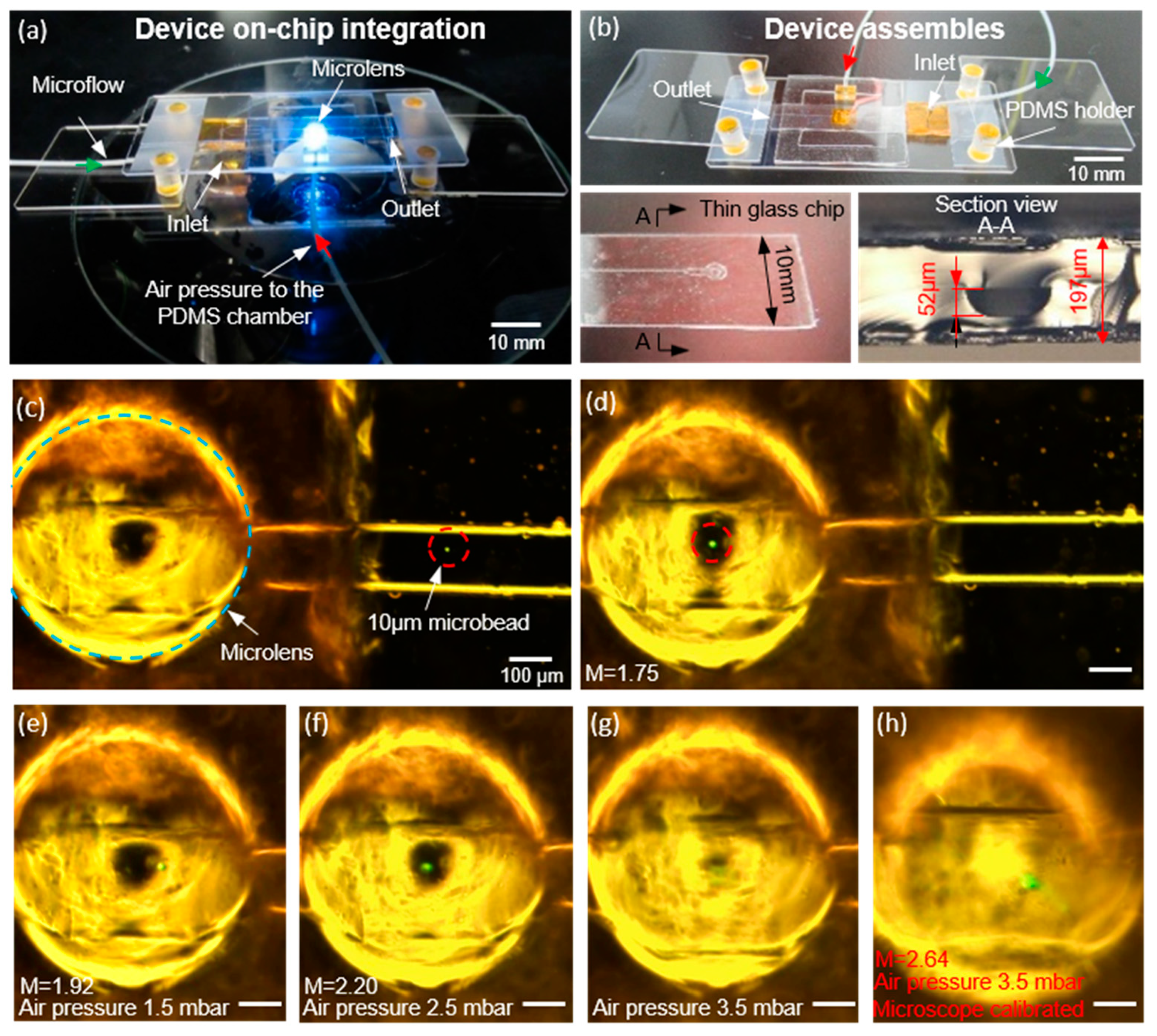
The fabricated device for the demonstration is shown in Figure 7a. We used a microfluidic thin glass chip (thickness approximately 200 μm) as the substrate glass chip for flowing the 10 μm fluorescent microbeads. The channel height was 50 μm, as shown in the section view A-A of Figure 7b. As the PDMS chamber was inflated under different pneumatic air pressures, different magnified images of the microbeads were obtained while they were flowing through the 500 μm-diameter microlens.
Figure 7c shows the magnified-to-scale microscope image of the fluorescent microbeads flowing in the microchannel. Figure 7d shows the same fluorescent microbeads flowing through the microlens with clear magnification. Images Figure 7e–h were taken while applying different pneumatic air pressures to the PDMS chamber. The image of Figure 7e shows magnification could be increased further whilst maintaining a relatively clear image when a pressure of 1.5 mbar was applied. Then, the pressure was raised to 2.5 mbar, and we were still able to produce a clearly magnified good quality image. However, when the pressure was increased to 3.5 mbar the image was out of focus, although by calibrating the microscope focus level a further magnified image was produced, but it was blurred.
The demonstration proved the feasibility of this optical system and the capability of producing different magnified images by integration with a microfluidic glass chip. Additionally, the optical properties of the system could be modified either by replacing the microlens or changing the PDMS chamber as resizing the chamber and changing the thickness of the PDMS layer. Thus, we developed a new pneumatically actuated magnification variable observation system which allows the exploitation of more chip-based applications. A video clip of this demonstration is provided in the supplementary information as Video S1.
4. Discussion
We have established an on-chip micro-optical system that magnifies changes by shifting the thin glass microlens positions within the device to produce more efficient deflections. As shown in the demonstration of Section 3.3 on optical performance, the glass microlens achieved a 100 μm displacement, and only 1.5 mbar of air pressure was required. This kind of small pressurized system is preferable in various biomedical related research to minimizing the malfunction of the parts due to a large amount of actuating pressures. Additionally, glass features can be optimized to improve their hardness and stability for such applications by fabricating microlenses with other glass materials such as silica or giving special treatments after the fabrication. Additionally, this actuation method was relatively sensitive to the external actuation compared to other microlens control mechanisms, such as piezoelectric actuation [32], where maximum curvature alteration of 12 μm was achieved on the microlens with a 100 V power supply. Similarly, in a hydraulic actuated liquid PDMS microlens system [33], the application of 350 mbar pressure was needed for the deflection of less than 10 μm in the system.
The only moving part in this device was the 100 μm-thick PDMS membrane layer, which showed a relatively high sensitivity, low power consumption, fast response, and reliable performance advantages. The PDMS layer oscillation frequency roughly reached 0.5 Hz, and this means a short response time when compared with thermal responsive actuated microlens control mechanisms [34], where an average of 20–25 s is needed to start response in the system. Although, from the actuation method point of view, this thin PDMS layer oscillating frequency is smaller than some other reported actuators made from glass [35] (frequency approximately 500 Hz) or metal memory alloys of Nickel and Titanium [36] (frequency 30 Hz). However, these types of high-frequency oscillations are usually difficult to produce a large volume of displacement in their systems. Additionally, the actuation requires a large amount of driven power and structurally complex. The suggested actuated method in this paper showed clear functional advantages and potentials in various fields, such as miniaturized optics on MEMS applications involve imaging and scanning utility.
A high-responsive infrared IR light microlens actuation method was reported [37], but the actuation power came from a continuous photo-reaction, which makes it difficult to control the optical adjustment processing or maintain the microlens at a certain magnification. Additionally, this one-way reaction process lasted a very short time, less than a few seconds. However, in the present pneumatic actuation system, the magnification can be kept at any point for a relatively long period of time using a constant air pressure supply. Finally, in thermal electro-wetting actuation [38], there are drawbacks of low efficiency and hysteretic behavior.
In previously cited methods, actuated microlenses were made from different materials including liquids, PDMS, or hydrogels, but some common weaknesses of those microlenses cannot be ignored in practical applications, such as microlens diameter limitations, gravity effect, shape distortion, mechanical instability, requiring a high voltage electrical supply, and the occurrence of interface friction and liquid evaporation. Our thin glass microlens actuation system overcomes those issues and offers the advantages of better transparency in most visible wavelength ranges, higher toughness, lower surface roughness, and higher flexibility of fabrication. For actuating the device, the average amount of air pressure was small (only a few mbar), and the pressure supplied from a constant pressure controller which could efficiently reduce the possibility of leaking air from the chamber and maintain the chamber’s defection at relatively long enough for observations. Furthermore, the customization of the device scale and magnification is simple, and can be realized by replacing the microlens or PDMS layer to control the absolute value for maximum deflections.
Additionally, a 300 μm-diameter water-filled thin glass microlens was further investigated under this microlens magnification principle to enhance its applications in nano-scale observation and magnification. From obtained results, it proved the feasibility of the concept by observing 750 nm diameter of microbeads on the glass slide surface. Along with further investigations and optimization, it is highly foreseeable to use this actuation method combine with this thin glass microlens applied various observations both at the micron and nano level. The related experimental setup and results demonstrated in the supplementary information as Figure S4 and Video S2.
5. Conclusions
In this study, we introduced a pneumatically actuated, magnification-adjustable optical system. The device itself consisted of a thin glass microlens, inflatable PMDS layer, and a microfluidic glass chip. The optical system fabrication and assembly process was rapid, manipulating the magnification was easy, and the flexible customization of the device was enabled as needed. Using different pneumatic air pressures in the demonstration, we obtained clear images of fluorescent microbeads at different magnifications. This device had the improvements of higher sensitivity to pressure, actuating method efficiency, and stable optical performance. In the future, we will further explore the potential applications of the system and promote its use in various chip-based assays, such as cell detection, high-throughput scanning, and optical sensor use.
Supplementary Materials
The following are available online at https://0-www-mdpi-com.brum.beds.ac.uk/2076-0825/9/3/73/s1, Figure S1: Magnification comparison under different diameters of microlenses. (a) The original size of 90 µm fluorescent microbeads. (b) The same microbeads viewed via 400 µm thin glass microlens and 1.45 of magnification achieved. (c) The microbeads put under 700 µm microlens and produced 1.64 magnification. (e) and (d) are the comparison images of observing a letter using a 1 mm diameter of the microlens. Unmark scale bar is 500 µm, Figure S2: Illustration of microlens connected with or without microchannel. (a) Image of the microlens arrays connected with microchannels. (b) The single (hollow) microlens without microchannel, Figure S3: The measuring results of different diameters of microlens with different magnifications at different positions. (a) This row of images are the 300 µm microlens produced magnification at different positions. (b) The 500 µm microlens produced magnification at different positions. (c) The 800 µm microlens produced magnification at different positions. (d) The 1 mm microlens produced magnification at different positions. Unmarked scale bar is 300 μm, Figure S4: The experiment of Nanobeads observation using thin glass microlens. From (a–c) are the 750 nm Nanobeads microscopic images under the different objective lens at various magnifications without microlens. (d) Positioning the 300 µm microlens over the Nanobeads area. (d) Calibrate the microscope focus through microlens onto the Nanobeads. Microlens magnified the previous image, the magnification power was approximately 1.48. (f) The illustration of the experimental setup for this experiment. (The experimental setup image is not to scale).
Author Contributions
All the authors have contributed their efforts to complete the paper. Y.A. performed the experiment, analyzed the results and prepared the original draft. Y.Y. supervised the work and reviewed and edited the manuscript. Y.T. project administration and funding acquisition. All authors have read and agreed to the published version of the manuscript.
Funding
This work was funded by the JSPS Grant-in-Aid for Scientific Research (No. 19H05338), RIKEN JRA, TEPCO Memorial Foundation, Amada Foundation, and NSG Foundation, Japan.
Conflicts of Interest
The authors declare no conflict of interest.
References
- Zhang, W.; Zou, Y.; Lin, T.; Chau, F.S.; Zhou, G. Development of Miniature Camera Module Integrated with Solid Tunable Lens Driven by MEMS-Thermal Actuator. J. Microelectromech. Syst. 2017, 26, 84–94. [Google Scholar] [CrossRef]
- Kuiper, S.; Hendriks, B.H.W. Variable-focus liquid lens for miniature cameras. Appl. Phys. Lett. 2004. [Google Scholar] [CrossRef] [Green Version]
- Bagramyan, A.; Galstian, T.; Saghatelyan, A. Motion-free endoscopic system for brain imaging at variable focal depth using liquid crystal lenses. J. Biophotonics 2017. [Google Scholar] [CrossRef] [PubMed]
- Kim, T.; Bin, M.Z.; Shin, R.; Kim, D.; Choi, W.; Park, C.; Kang, S. Replication of high refractive index glass microlens array by imprinting in conjunction with laser assisted rapid surface heating for high resolution confocal microscopy imaging. Opt. Express 2019. [Google Scholar] [CrossRef] [PubMed]
- Schwertz, K. An Introduction to the Optics Manufacturing Process. OptoMechanics (OPTI 521) Report. 2008. [Google Scholar]
- Liu, H.; Chen, F.; Wang, X.; Yang, Q.; Zhang, D.; Si, J.; Hou, X. Photoetching of spherical microlenses on glasses using a femtosecond laser. Opt. Commun. 2009. [Google Scholar] [CrossRef]
- Razpet, N.; Susman, K.; Čepič, M. Experimental demonstration of longitudinal magnification. Phys. Educ. 2009. [Google Scholar] [CrossRef]
- Ren, H.; Wu, S.-T. Tunable-focus liquid microlens array using dielectrophoretic effect. Opt. Express 2008, 16, 2646. [Google Scholar] [CrossRef]
- Huang, X.; Cheng, C.M.; Wang, L.; Wang, B.; Su, C.C.; Ho, M.S.; LeDuc, P.R.; Lin, Q. Thermally tunable polymer microlenses. Appl. Phys. Lett. 2008, 92, 251904. [Google Scholar] [CrossRef]
- Krupenkin, T.; Yang, S.; Mach, P. Tunable liquid microlens. Appl. Phys. Lett. 2003, 82, 316–318. [Google Scholar] [CrossRef]
- Zou, Y.; Chau, F.S.; Zhou, G. Miniature solid tunable lenses and their applications: A review. Sens. Mater. 2017, 29, 323–334. [Google Scholar] [CrossRef] [Green Version]
- Ji, S.; Yin, K.; Mackey, M.; Brister, A.; Ponting, M.; Baer, E. Polymeric nanolayered gradient refractive index lenses: Technology review and introduction of spherical gradient refractive index ball lenses. Opt. Eng. 2013. [Google Scholar] [CrossRef]
- Zeng, X.; Jiang, H. Liquid tunable microlenses based on MEMS techniques. J. Phys. D Appl. Phys. 2013, 46. [Google Scholar] [CrossRef] [PubMed]
- Farghaly, M.A.; Hanke, U.; Akram, M.N.; Halvorsen, E. Trial functions for reduced-order models of piezoelectrically actuated microelectromechanical systems tunable lenses. Opt. Eng. 2018, 57, 1. [Google Scholar] [CrossRef]
- Li, L.; Wang, J.-H.; Wang, Q.-H.; Wu, S.-T. Displaceable and focus-tunable electrowetting optofluidic lens. Opt. Express 2018, 26, 25839. [Google Scholar] [CrossRef]
- Lee, S.W.; Lee, S.S. Focal tunable liquid lens integrated with an electromagnetic actuator. Appl. Phys. Lett. 2007. [Google Scholar] [CrossRef] [Green Version]
- Ashtiani, A.O.; Jiang, H. Tunable microlens actuated via a thermoelectrically driven liquid heat engine. J. Appl. Phys. 2014, 115. [Google Scholar] [CrossRef] [Green Version]
- Sarrazin, F.; Salmon, J.B.; Talaga, D.; Servant, L. Chemical reaction imaging within microfluidic devices using confocal raman spectroscopy: The case of water and deuterium oxide as a model system. Anal. Chem. 2008. [Google Scholar] [CrossRef]
- Lei, K.F.; Lee, K.F.; Lee, M.Y. Development of a flexible PDMS capacitive pressure sensor for plantar pressure measurement. Microelectron. Eng. 2012, 99, 1–5. [Google Scholar] [CrossRef]
- Tanaka, Y.; Noguchi, Y.; Yalikun, Y.; Kamamichi, N. Earthworm muscle driven bio-micropump. Sens. Actuators B Chem. 2017, 242, 1186–1192. [Google Scholar] [CrossRef]
- Yalikun, Y.; Hosokawa, Y.; Iino, T.; Tanaka, Y. An all-glass 12 μm ultra-thin and flexible micro-fluidic chip fabricated by femtosecond laser processing. Lab Chip 2016, 16, 2427–2433. [Google Scholar] [CrossRef] [PubMed] [Green Version]
- Tanaka, Y. Electric actuating valves incorporated into an all glass-based microchip exploiting the flexibility of ultra thin glass. RSC Adv. 2013, 3, 10213–10220. [Google Scholar] [CrossRef]
- Tanaka, Y. A Peristaltic Pump Integrated on a 100% Glass Microchip Using Computer Controlled Piezoelectric Actuators. Micromachines 2014, 5, 289–299. [Google Scholar] [CrossRef]
- Yalikun, Y.; Tanaka, Y. Large-Scale Integration of All-Glass Valves on a Microfluidic Device. Micromachines 2016, 7, 83. [Google Scholar] [CrossRef] [Green Version]
- Ottevaere, H.; Cox, R.; Herzig, H.P.; Miyashita, T.; Naessens, K.; Taghizadeh, M.; Völkel, R.; Woo, H.J.; Thienpont, H. Comparing Glass and Plastic Refractive Microlenses Fabricated with Different Technologies; IOP Publishing Ltd.: Bristol, UK, 2006. [Google Scholar]
- Aishan, Y.; Yalikun, Y.; Amaya, S.; Shen, Y.; Tanaka, Y. Thin glass micro-dome structure based microlens fabricated by accurate thermal expansion of microcavities. Appl. Phys. Lett. 2019. [Google Scholar] [CrossRef]
- Aishan, Y.; Yalikun, Y.; Funano, S.I.; Shen, Y.; Tanaka, Y. Accurate rotation of ultra-Thin glass chamber for single-cell multidirectional observation. Appl. Phys. Express 2020. [Google Scholar] [CrossRef]
- Ens, J.; Lawrence, P. An Investigation of Methods for Determining Depth from Focus. IEEE Trans. Pattern Anal. Mach. Intell. 1993. [Google Scholar] [CrossRef]
- Svedin, N.; Kälvesten, E.; Stemme, E.; Stemme, G. A new silicon gas-flow sensor based on lift force. J. Microelectromech. Syst. 1998, 7, 303–308. [Google Scholar] [CrossRef]
- Czaplewski, D.A.; Ilic, B.R.; Zalalutdinov, M.; Olbricht, W.L.; Zehnder, A.T.; Craighead, H.G.; Michalske, T.A. A micromechanical flow sensor for microfluidic applications. J. Microelectromech. Syst. 2004, 13, 576–585. [Google Scholar] [CrossRef]
- Mishra, R.; Grange, W.; Hegner, M. Rapid and Reliable Calibration of Laser Beam Deflection System for Microcantilever-Based Sensor Setups. J. Sens. 2012, 2012, 1–6. [Google Scholar] [CrossRef]
- Merlo, S.; Crisà, E.; Giusti, D.; Ferrera, M.; Soldo, M. Characterization of tunable micro-lenses with a versatile optical measuring system. Sensors 2018, 18, 4396. [Google Scholar] [CrossRef] [PubMed] [Green Version]
- Chronis, N.; Liu, G.; Jeong, K.-H.; Lee, L. Tunable liquid-filled microlens array integrated with microfluidic network. Opt. Express 2003, 11, 2370. [Google Scholar] [CrossRef]
- Dong, L.; Agarwal, A.K.; Beebe, D.J.; Jiang, H. Adaptive liquid microlenses activated by stimuli-responsive hydrogels. Nature 2006, 442, 551–554. [Google Scholar] [CrossRef] [PubMed]
- Hoelzle, D.J.; Chan, C.K.; Scott, M.B.; Lake, M.A.; Rowat, A.C. A large displacement, high frequency, underwater microelectromechanical systems actuator. J. Appl. Phys. 2015. [Google Scholar] [CrossRef] [Green Version]
- Gill, J.J.; Ho, K.; Carman, G.P. Three-dimensional thin-film shape memory alloy microactuator with two-way effect. J. Microelectromech. Syst. 2002. [Google Scholar] [CrossRef]
- Zeng, X.; Jiang, H. Tunable liquid microlens actuated by infrared light-responsive hydrogel. Appl. Phys. Lett. 2008, 93, 1–4. [Google Scholar] [CrossRef] [Green Version]
- De Volder, M.; Ceyssens, F.; Reynaerts, D.; Puers, R. Microsized piston-cylinder pneumatic and hydraulic actuators fabricated by lithography. J. Microelectromechanical Syst. 2009. [Google Scholar] [CrossRef]
Figure 1.
Schematic drawings of the optical observation method and the imaging principle of the system. (a) When no external air pressure is applied to the closed Polydimethylsiloxane (PDMS) chamber, the optical system keeps the microlens’ original position and magnification. (b) When air pressure is applied, the microlens position is lifted as the chamber is inflated with air. The system’s magnification is changing along with the microlens position altering during the process. (c) The imaging principle of this system that achieves various magnifications by changing the microlens position between the objective lens and the target.

Figure 2.
Main steps for the thin glass microlens fabrication. (a) Microcavities were prepared on one glass slide as the substrate. (b) Two glass slides were pre-bonded together by gently pressing. (c) The pre-bonded slides were heated in a vacuum for fusion bonding. A biconvex lens-like deformation occurred on the glass slides due to the thermal expansion of the trapped air inside of the microcavities. (d) After proper cooling, the glass microlens was permanently formed.

Figure 3.
Illustration of the PDMS chamber inflation measurement experimental setup. The PDMS layer deflections h were detected by the laser beam displacement distance d that was recorded with an oscilloscope. Enlarge image A illustrates the attaching structure of the microlens to the PDMS layer (this image is not to scale).

Figure 4.
Characterization of the fabricated microlens. (a) Microscopic side view of a thin glass microlens that is connected with the microchannel for liquid (oil) insertion. (b) Top view of the microlens and its magnification feature. (c) The single microlens measured diameter and height. (d) A surface profiler image.

Figure 5.
The 500 μm-thick oil-filled microlens used in an optical evaluation experiment setup and the obtained results. (a) The concept image of the experiment. The distance from the microlens to the glass micro-ruler plate changes. (b) Photo of the actual experimental setup. The microlens was attached to the jig holder and placed over the micro-ruler plate under the microscope. (c–h) Images captured at different distances to the micro-ruler plate, progressively changed by 100 μm from one image to the next. Each scale bar is 100 μm.

Figure 6.
Device for the PDMS layer inflation measurement and the obtained results. (a) Photo of the fabricated device. (b) Graph results of the two different thicknesses of the PDMS layers inflations, measured as deflected heights at various air pressures.
Figure 6.
Device for the PDMS layer inflation measurement and the obtained results. (a) Photo of the fabricated device. (b) Graph results of the two different thicknesses of the PDMS layers inflations, measured as deflected heights at various air pressures.

Figure 7.
The on-chip optical system and some experimental results. (a) The device setup under the microscope; air pressure was supplied into the PDMS chamber via the tube marked by the red arrow. The green arrow points to the tube with fluorescent microbeads flowing into the microchannel. (b) The device assembly. (c) Images of the microscope focus calibrated on the glass chip. (d) Microbeads flowing in the microlens in an image that was obtained without any calibrations or application of air pressure into the PDMS chamber. (e–h) Images of the microbeads at different magnified sizes when different air pressures were applied to the PDMS chamber.

© 2020 by the authors. Licensee MDPI, Basel, Switzerland. This article is an open access article distributed under the terms and conditions of the Creative Commons Attribution (CC BY) license (http://creativecommons.org/licenses/by/4.0/).
Share and Cite
MDPI and ACS Style
Aishan, Y.; Yalikun, Y.; Tanaka, Y. Pneumatically Actuated Thin Glass Microlens for On-Chip Multi-Magnification Observations. Actuators 2020, 9, 73. https://0-doi-org.brum.beds.ac.uk/10.3390/act9030073
AMA Style
Aishan Y, Yalikun Y, Tanaka Y. Pneumatically Actuated Thin Glass Microlens for On-Chip Multi-Magnification Observations. Actuators. 2020; 9(3):73. https://0-doi-org.brum.beds.ac.uk/10.3390/act9030073
Chicago/Turabian StyleAishan, Yusufu, Yaxiaer Yalikun, and Yo Tanaka. 2020. "Pneumatically Actuated Thin Glass Microlens for On-Chip Multi-Magnification Observations" Actuators 9, no. 3: 73. https://0-doi-org.brum.beds.ac.uk/10.3390/act9030073
Note that from the first issue of 2016, this journal uses article numbers instead of page numbers. See further details here.