Proof of Principle of a Rotating Actuator Based on Magnetostrictive Material with Simultaneous Vibration Amplitude

1
Professorship for Adaptronics and Lightweight Design, Chemnitz University of Technology, 09126 Chemnitz, Germany
2
Fraunhofer Institute for Machine Tools and Forming Technology IWU, 01187 Dresden, Germany
*
Author to whom correspondence should be addressed.
Actuators 2020, 9(3), 81; https://0-doi-org.brum.beds.ac.uk/10.3390/act9030081
Submission received: 24 August 2020
/
Revised: 4 September 2020
/
Accepted: 7 September 2020
/
Published: 9 September 2020
(This article belongs to the Section Actuator Materials)
Abstract
:Magnetostrictive materials are a group of smart materials with comparable properties to piezoelectric materials regarding strain and operating frequency. In contrast, the Curie temperature is much higher and the principle effect allows different actuator designs. Especially in the case of rotating actuators in ultrasonic assisted machining, a high potential is seen for a simplified energy transmission. In the study, a test stand for a rotating actuator with simultaneous vibration in longitudinal direction was designed to show the proof of principle for this idea. It was shown that the current inducing the magnetic field as well as its frequency influence the amplitude of the rotating actuator. This is a first step to developing a rotating actuator for ultrasonic machining.
1. Introduction
1.1. Challenges for Dynamic Additional Axes for Rotating Tools
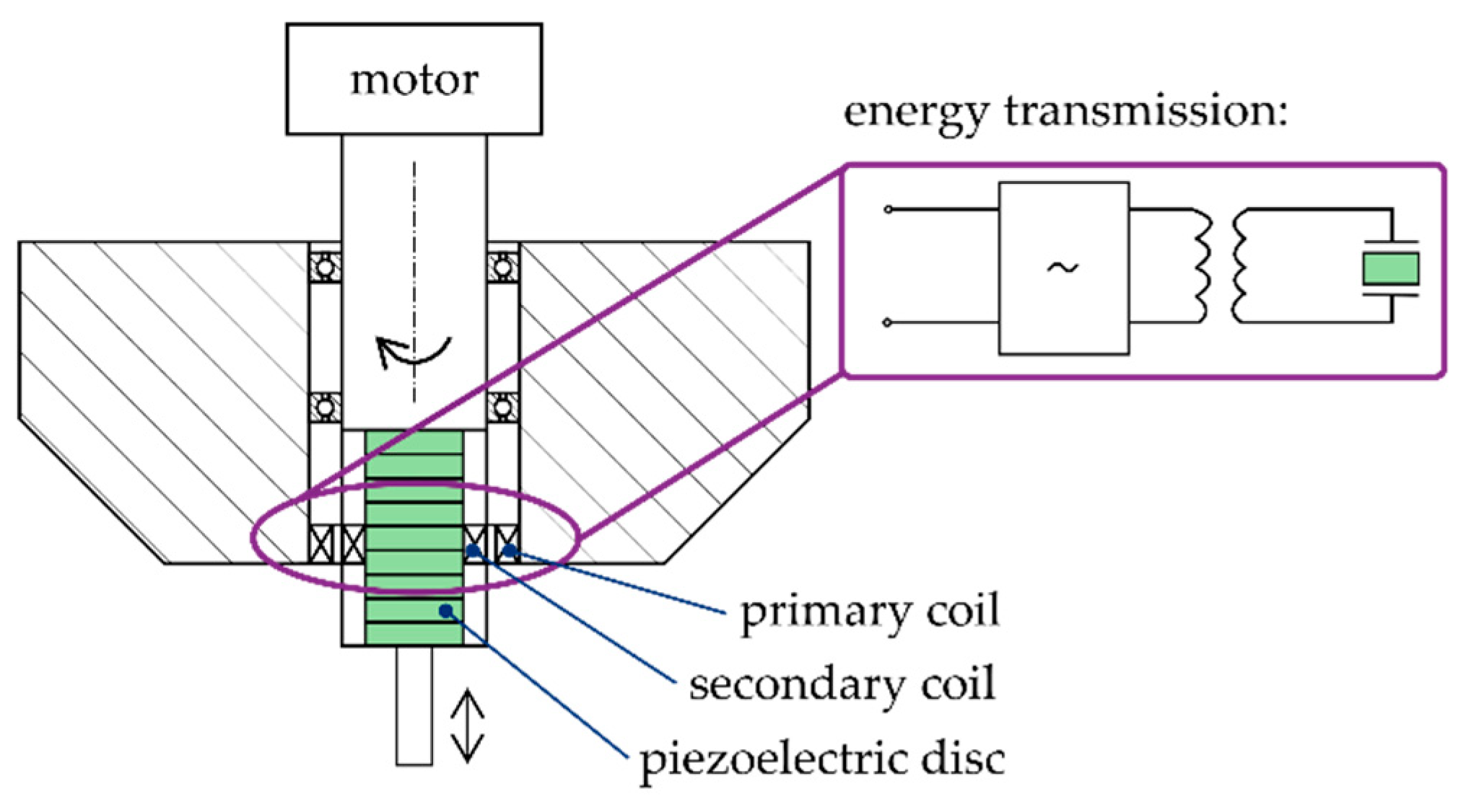
It is a great challenge of our time to develop highly efficient production processes for the manufacturing of tribological surfaces using superimposed actuator movements [1]. One application case is ultrasonic assisted cutting. It has several advantages compared to a conventional cutting process. It is possible to decrease the cutting force and increase the tool lifetime in this way [2]. Furthermore, a reduction of the burr or high productive micro structuring is possible. Preferably, piezoelectric ceramics are utilized in such systems to generate the required vibration during the process [3]. Ultrasonic assisted machining is widely used in various machining processes [2,3,4]. The principle design of ultrasonic systems is similarly structured. Piezoelectric discs are stacked together with electrodes between them [4,5]. At both ends are mass pieces to adjust the eigenfrequency of the system. The movement of the system is controlled electrically by the current applied to the electrodes. This is unproblematic if the tool does not rotate, e.g., in a turning process. In case of milling, however, the tool rotates and the question of energy transfer must be solved. This is usually achieved by induction with a primary and secondary coil [6], which is illustrated in Figure 1. The primary coil is fixed to the machine and the secondary coil is integrated in the rotating tool. The alternating power signal is transmitted from the primary coil to the secondary coil via electromagnetic induction.
The negative effects are a reduced energy efficiency and an increased rotating mass of the tool. Magnetostrictive material can overcome these disadvantages because of its different physical principles as explained in the following.
1.2. Basics and Applications of Magnetostrictive Materials
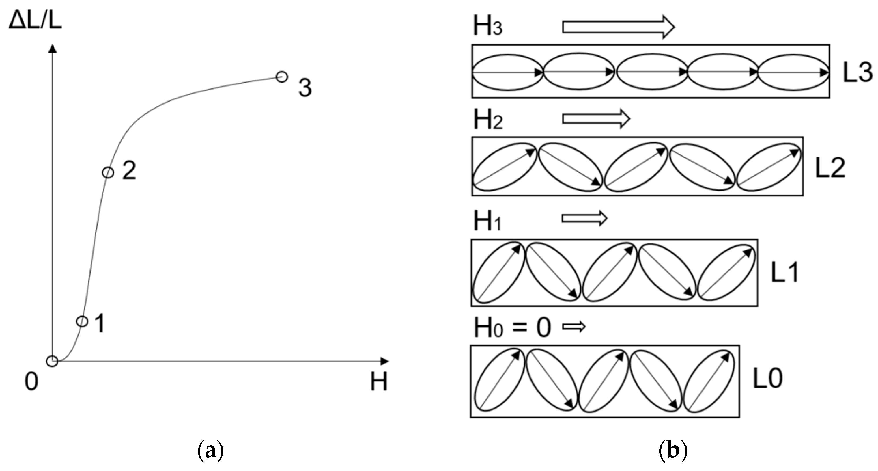
Magnetostrictive materials, like Terfenol-D, belong to the group of smart materials or active materials [7]. If a magnetic field is applied to a sample, the magnetic domains will be reoriented in this direction and the material will be elongated. Figure 2 illustrates this effect.
In the case of no magnetic field (H = 0), the magnetic domains are randomly oriented. If a magnetic field is applied (H1), the magnetic domains start to align in the direction of the applied field and reach a particular elongation (∆L1). With an increasing magnetic field (H2), the magnetic domains align even more to the point of saturation (H3) with absolute orientation of the domains in direction of the magnetic field and thereby a maximum elongation (∆L3).
Magnetostrictive materials can be used in different application scenerios. Thin film applications, e.g., micro pumps or micro loudspeakers, have been developed [9,10]. An active damper is one possible application for massive magnetostrictive material [11,12,13]. In the application field of cutting processes, a hybrid longitudinal-torsional magnetostrictive ultrasonic transducer was presented [14,15]. The desired eigenfrequency was above 20 kHz and the longitudinal amplitude was 0.6 µm. However, the design is not convenient for rotation movement of the tool, which is an important difference to the simultaneous rotating and vibrating tool principle of our work. Nowadays, linear actuators with a diameter of 1.98 inch, a length of 5.52 inch, a maximum step output displacement of 7 µm, and operating frequency range up to 20 kHz are commercially available [16]. Magnetostrictive materials can also be used as sensors. For example, a contactless torque measurement of a drill is possible [17]. However, the sensory use is not the focus of this article.
1.3. Comparison of Piezoeletric and Magnetostrictive Material and Rotional Actuator Design
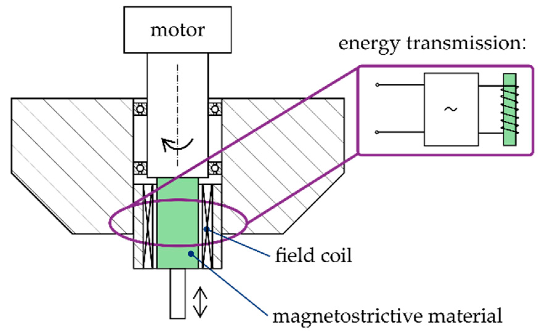
One major disadvantage of piezoelectric systems is the difficult energy transmission to the rotating actuator because a primary and secondary coil is needed, as shown in Figure 1. In the case of magnetostrictive materials, only one coil is necessary, which is presented in Figure 3. In this way, it could be possible to lower the rotating mass of the tool and increase the energy efficiency.
Table 1 shows a comparison of the magnetostrictive and piezoelectric material. The maximum strain of piezoelectric materials und magnetostrictive materials are comparable, but especially the Curie temperature is higher in the case of the magnetostrictive material. Therefore, the operating range could be higher.
In summary, magnetostrictive materials have a high potential to be utilized in rotating actuators because of their inherent material properties and their actuation principle. The authors of this paper are not aware of any articles about a rotating actuator based on magnetostrictive materials. In order to close this substantial research gap, the aim of this work is to provide a proof of principle for a rotating actuator with superimposed linear vibration.
2. Materials, Test Stand, Tests and Design of Experiments
2.1. Materials and Test Stand
Cylindrical rods with a diameter of 10 mm and a length of 50 mm made from Terfenol-D provided by the company TdVib LLC were used. For the system design, three requirements are essential:
- the generation of a rotary movement (target value 2000 rpm),
- the generation of a switching magnetic field, which is high enough for the actuation of the sample (20 kA/m based on [19]),
- a system to measure displacements in µm-range, which is insensitive to the magnetic flux of the sample.
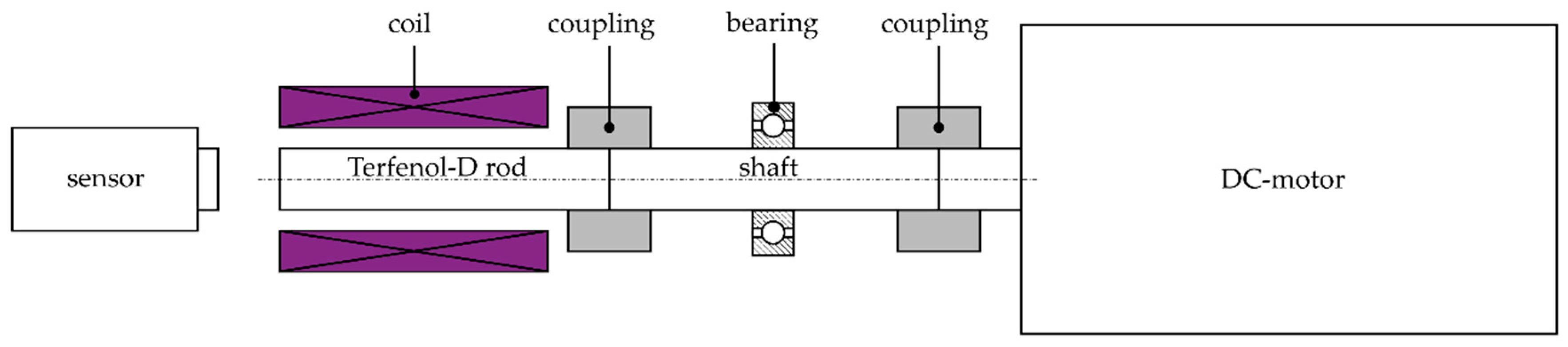
In compliance with these requirements, a first system design, as shown in Figure 4, was developed.
The DC-motor generates a rotational movement of the rod. The coil, powered by an AC-amplifier, provides the switching magnetic field. The measurement system is an optical system. Therefore, a feedback effect on the test stand should be neglectable. The laser of the measurement system was focused on the Terfenol-D rod center to reduce the influence of unbalanced movements. A flexible coupling is used to compensate small angular, axial and parallel deviations. For the coil, an enameled copper wire was warped on a 3D-printed coil body made out of polylactic acid.
2.2. Tests and Validation
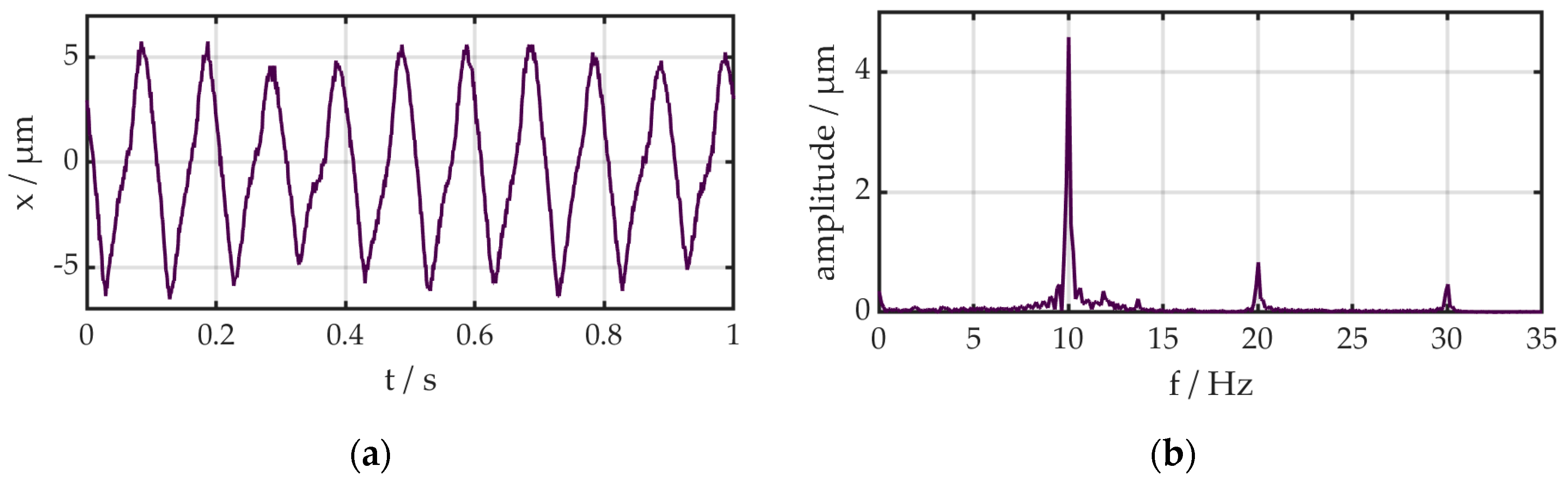
The specifications of the DC-motor are a maximum rotation speed of 3000 rpm, a power of 250 W and a maximum torque of 0.8 Nm. Due to the power supply, the range is limited from 82 rpm to 2150 rpm. In this range, the behavior (voltage to rotation speed) is linear. As a sensor system, a laser vibrometer was used, as shown in Figure 5. The laser vibrometer has been calibrated and allows a resolution in the pm-range, but minimal variations within the amplitudes are visible. This could be caused by small changes of the magnetic field within the self-winded coil.
For the dimensioning of the coil, a simulation was carried out. The coil was simulated with the software ANSYS Maxwell 19.1 [20] under DC-conditions with a copper wire diameter of 0.82 mm. This thickness is a compromise of using a high current and winding the copper wire by hand. According to the manufacturer’s data sheet [19], a minimum magnetic field of around 20 kA/m is necessary to achieve 0.05% elongation. In order to maximize the magnetic field inside the coil, the air gap was minimized. A disadvantage of this design is that a measurement of the magnetic field with a sample is not possible anymore. So the sample was not a part of the simulation. Due to this reason, a magnetic field of 50 kA/m using a current of 2.8 A and DC-conditions was the goal of the simulation without a sample. This oversizing from 20 up to 50 kA/m was selected to guarantee a minimum magnetic field for an elongation. The calculated winding number of the coil was 910. Due to the approximation of a magnetostatic-DC-simulation, a winding number of 1000 was chosen. In a pre-test, a maximum magnetic field of 51 kA/m (DC, 2.8 A) was measured with a hall-sensor. Furthermore, the measured elongation of the sample in combination with the coil is 0.035% (DC, 2.8 A), which is slightly less than expected.
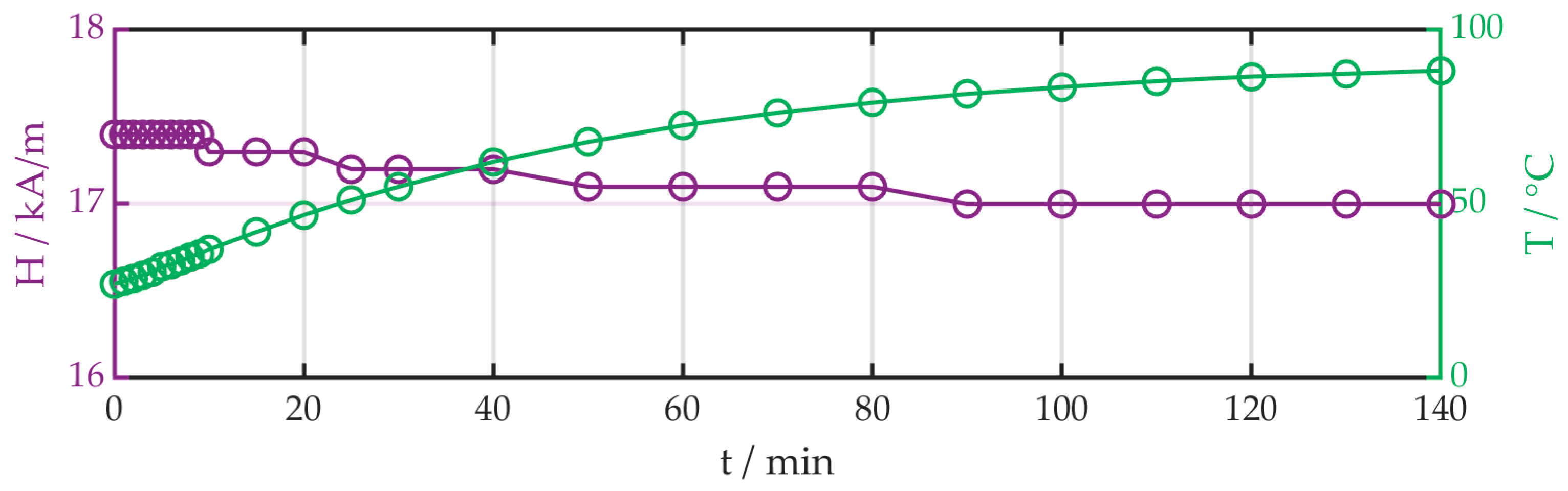
In a temperature test, the influence of the heating through the AC-current was investigated. The amplitude of the current was 1.4 A with a frequency of 10 Hz. An offset of 1.4 A was used because the power supply could only generate a positive current. Therefore, the current alternates between 0 A and 2.8 A. The magnetic field and the temperature in the center point of the coil was measured. The measurement was stopped when the temperature change was under 1 K during 10 min. The diagram is shown in Figure 6.
The magnetic field strength remained approximately constant during the measurement, but the temperature increased from 27 °C up to 90 °C. In the first 10 min, the temperature changed from 27.8 °C up to 37.0 °C. The temperature-dependent behavior of the Terfenol-D should not be influenced during the measurement so each measurement was limited to a maximum of 10 min. The test stand fulfilled the requirements and crucial parameters (temperature, operating frequencies) were under control.
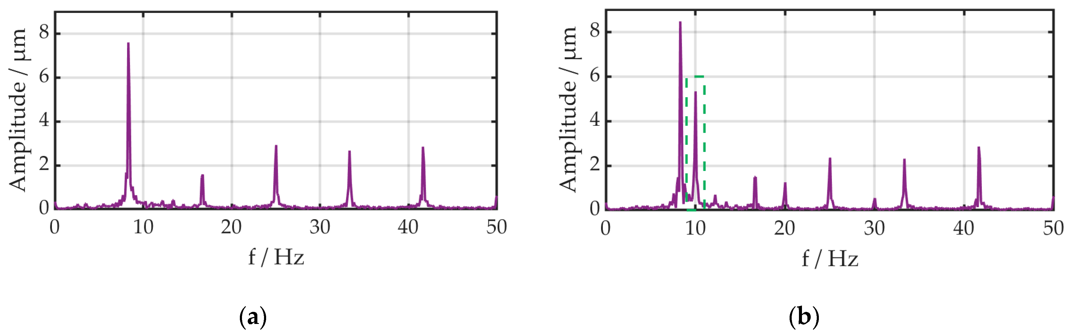
During the validation test of the system, the operating frequency was detected, see Figure 8. The operating frequency was around 8.3 Hz. The reason for this could be an unbalanced system or an irregular surface of the front face of the rod. Therefore, the frequency of displacement should not fall into this range. To improve the signal quality in further analyses, a bandpass filter with a range of 9 to 11 Hz including the vibration frequency of 10 Hz was used.
The goal, the proof of principle for a rotating actuator, has been demonstrated. In further experiments, the influence of the operating parameters (rotation speed, currents amplitude, frequency of the current) is investigated to get a deeper understanding of the system. The investigation consists of three experiments. In the first experiment, the influence of rotation speed on displacement is determined. Secondly, the amplitude of the current is varied to determine the influence on the elongation of the rod. With an increasing current, the magnetic field should increase, too. In the last experiment, the relationship between the frequency of the current and the displacement is investigated. The displacement should decrease with increasing frequency because of the self-inductance of the coil, based on Lenz’s law. According to this, an opposed current is induced and, therefore, a fast switching of the magnetic field is impeded in this case. All experiments are summarized in Table 3.
3. Results
For the data analysis, Matlab R2019b [21] was used. In all experiments, a digital FIR bandpass filter was used for adapted presentation of the data [22]. The filter order was 500, the frequency range from 9 Hz to 11 Hz and the sample rate 1000 Hz. The high filter order was necessary in combination with the small frequency range.
3.1. Influence of Rotation Speed
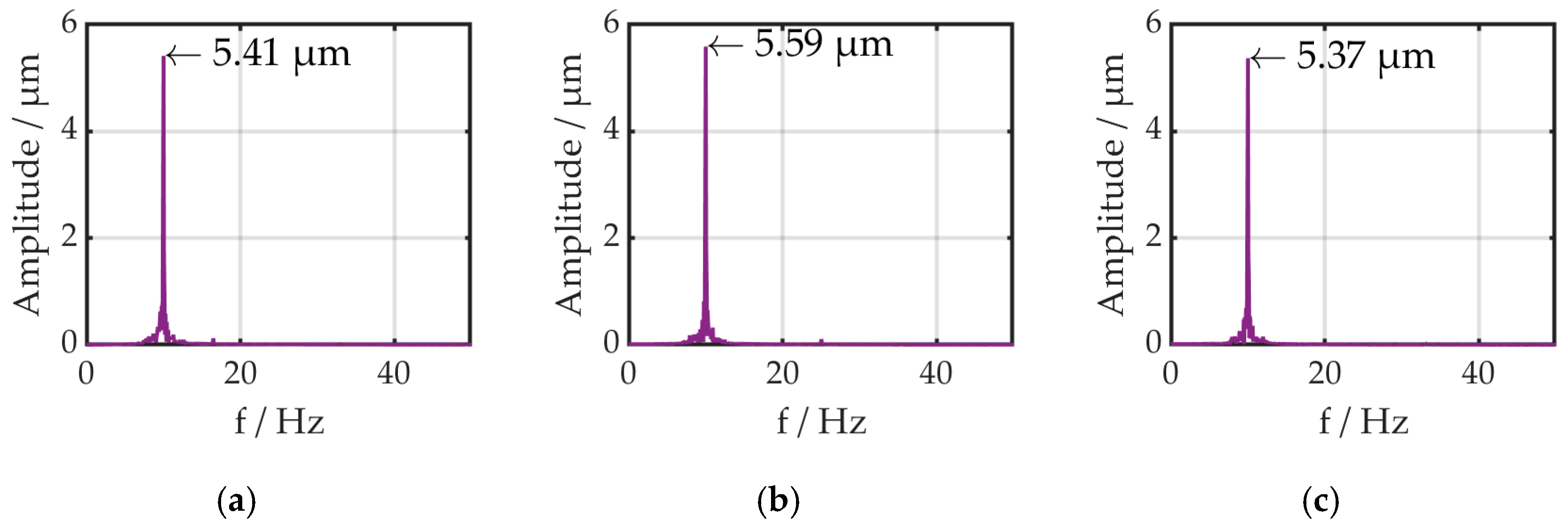
During this experiment, the amplitude (1.4 A) and the frequency (10 Hz) of the current were constant. The rotation speed was varied from 1000 rpm to 1500 rpm up to 2000 rpm. The displacement was measured. The results are shown in Figure 9.
The amplitude varied from 5.41 µm up to 5.59 µm to 5.37 µm. The deviation is 8% and so the influence of the rotation speed is minimal.
3.2. Influence of Currents Amplitude
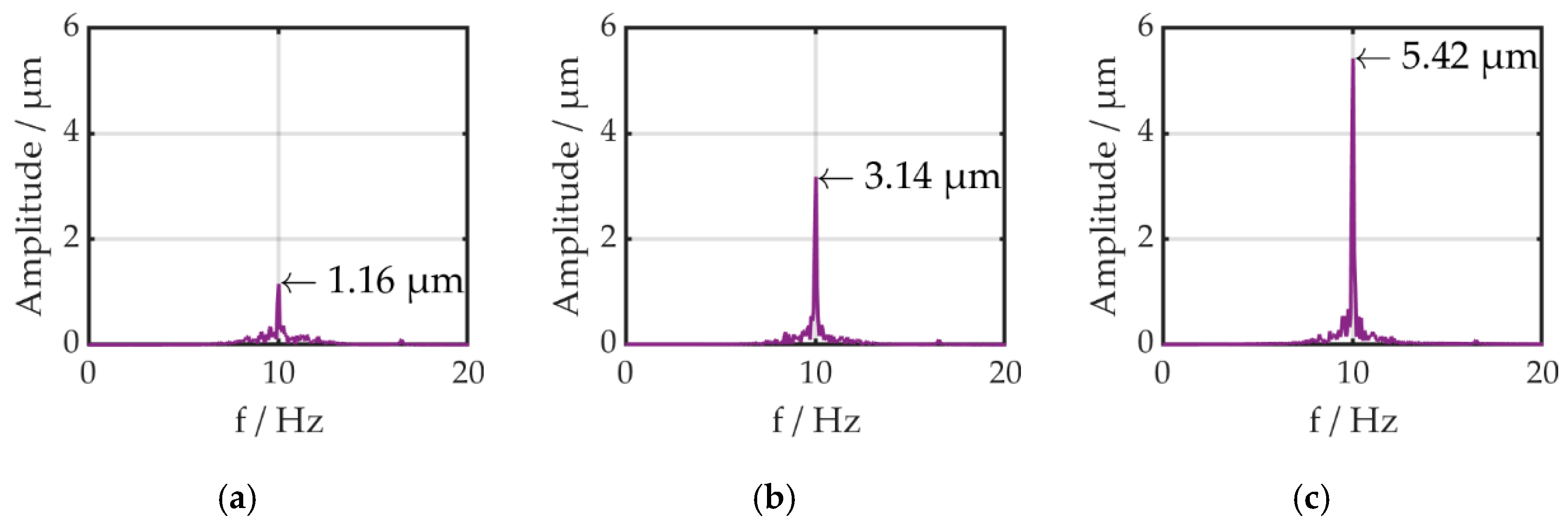
In this case, the rotation speed (1000 rpm) and the frequency of the current (10 Hz) are constant. The amplitude of the current was adjusted to 0.6, 1.0 and 1.4 A. The diagrams are shown in Figure 10.
The amplitude of the displacement increases almost linearly with increasing amplitude of the current from 1.2 to 3.1 up to 5.4 µm.
3.3. Influence of the Current Frequency
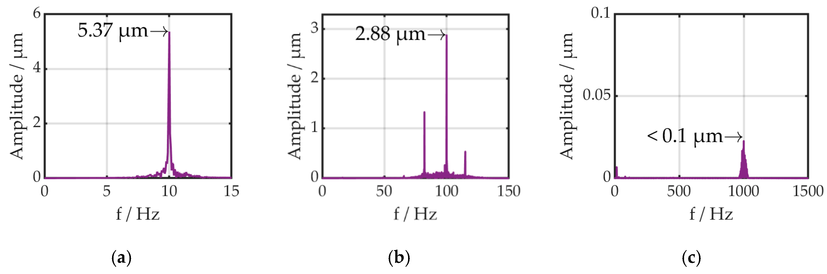
In the last experiment, the rotation speed (1000 rpm) and the amplitude of the current (1.4 A) were constant and the frequency of the current was changed from 10 to 100 and 1000 Hz. The bandpass filter was modified for the 100 Hz setup (frequency range 99–101 Hz) and the 1000 Hz (frequency range 999–1001 Hz, sample rate 10 kHz). The displacement decreased with the increasing frequency (5.4 to 2.9 up to <0.1 µm). The results are presented in Figure 11.
4. Discussion
In the first experiments on the influence of the rotation speed, no trend is identifiable. The variation of the amplitude is only 0.22 µm and can be explained by the imbalance or unevenness of the front surface. A stable amplitude is an important requirement for a cutting process. The maximum amplitude of 5.59 µm of all experiments under AC conditions corresponds to 0.011% elongation. This is much less than expected from the manufacturer’s specification of Terfenol-D (0.08–0.12%) [23]. One reason for this is that the specifications refer to DC and therefore higher strains can be expected. Nevertheless, this amplitude allows to produce microstructures during milling [24]. In the referred article, a piezoelectric-based ultrasonic system with a maximum amplitude of 6.6 µm was used to produce surfaces with small dimples. A disadvantage of such ultrasonic systems is that they are working in a fixed resonance frequency to maintain the maximum amplitude in operation. In consequence, the system is limited to its operating frequency range with technically feasible amplitudes. Non-resonant systems, like the presented one, overcome this disadvantage and allow significantly expanded possibilities for the design of microstructures.
In the second experiment, the amplitude of the current was varied and the displacement amplitude increased from 1.16 µm up to 5.42 µm. This closely linear increase corresponds with the literature [7] and the producer specifications [19]. It also shows that the point of saturation is not achieved during the experiments and so the maximum amplitude could increase further.
In the last experiment, the variation of the current frequency was the point of interest. The amplitude decreased from 5.37 µm down to less than 0.1 µm with an increase of the current frequency. The reason for this behavior is the self-inductance of the coil, based on Lenz’s law [25]. A change of the magnetic field induced a current in the coil in the opposite direction. The effect is also called induced resistance. An increase in frequency enlarged this resistance and reduced the magnetic field. In the case of 1000 Hz, the magnetic field is apparently not sufficient to elongate the magnetostrictive material. The results suggest that higher frequencies with a sufficient amplitude of the sample are difficult to achieve in non-resonant mode.
5. Conclusions
Smart materials have the potential to transform manufacturing technology significantly. Especially in the case of ultrasonic assisted cutting, piezoelectric systems have several advantages but few disadvantages, like higher rotating mass because of a second coil or lower Curie temperature, too. Magnetostrictive materials could overcome these boundaries. In a first step, a simple test stand was developed. In general, the proof of concept was successful. A rotating actuator based on magnetostrictive material with simultaneous vibration amplitude was realized and tested. The following observations were made:
- The rotation speed has only a minimal influence on the amplitude of the displacement (Variation 0.22 µm).
- The displacement amplitude increases almost linearly with an increasing amplitude of the current up to 5.42 µm.
- The displacement amplitude decreases with an increasing current frequency due to the reduction of the magnetic field (during 1000 Hz an amplitude less than 0.1 µm).
The results show that the idea of a rotating actuator based on magnetostrictive material with simultaneous vibration amplitude works in principle. It is possible to generate constant vibration amplitudes up to 5.42 µm, and these can probably be increased even further. The test stand is limited because of the maximum current of the power supply and the corresponding maximum magnetic field. The described mechanical vibrations may have been caused by uneven surfaces or an unbalanced system. Therefore, it is possible to suppress this factor by a more precise assembly of the system and a post-processing of mechanical parts. A thicker diameter of the coil wire would allow using higher current. Therefore, less windings for the same amount of magnetic field are necessary and so the self-inductance could be reduced significantly. Furthermore, laminated rods made out of Terfenol-D could be used to decrease eddy current losses through high frequencies. For ultrasonic applications, Terfenol-D should be tested in resonance-mode. In this way, high amplitudes during high frequencies could be achieved. In general, this work is focused on experimental methods. For a deeper understanding of the micro phenomena, a transient simulation model would be helpful.
Based on these findings and ideas, a knowledge base on this topic was created in order to design a prototype for a milling machine in the next step. In the future it will be possible to modify the milling machine, optimize processes and finally manufacture workpieces more productively or with higher quality.
Author Contributions
C.T. did the conceptualization and writing of the original draft. Q.L. was responsible for the data curation, formal analysis and visualization under the supervision of C.T., S.K. and W.-G.D. contributed with substantial review and editing. All authors have read and agreed to the published version of the manuscript.
Funding
The publication of this article was funded by Chemnitz University of Technology.
Conflicts of Interest
The authors declare no conflict of interest.
References
- Greco, A.; Raphaelson, S.; Ehmann, K.; Wang, Q.J.; Lin, C. Surface texturing of tribological interfaces using the vibromechanical texturing method. J. Manuf. Sci. Eng. 2009, 131, 061005. [Google Scholar] [CrossRef]
- Xu, W.X.; Zhang, L.C. Ultrasonic vibration-assisted machining: Principle, design and application. Adv. Manuf. 2015, 3, 173–192. [Google Scholar] [CrossRef]
- Brehl, D.E.; Dow, T.A. Review of vibration-assisted machining. Precis. Eng. 2008, 32, 153–172. [Google Scholar] [CrossRef]
- Gallego-Juárez, J.A.; Graff, K.F. Power Ultrasonics: Applications of High-Intensity Ultrasound; Elsevier: Amsterdam, The Netherlands, 2014. [Google Scholar]
- Hemsel, T.; Bornmann, P.; Morita, T.; Sondermann-Woelke, C.; Sextro, W. Reliability analysis of ultrasonic power transducers. Arch. Appl. Mech. 2016, 86, 1707–1713. [Google Scholar] [CrossRef]
- Zhu, X.M.; Lin, B.; Liu, L.P. Review on the development of the accessory rotary ultrasonic machining tools. In Applied Mechanics and Materials; Trans Tech Publications Ltd.: Stafa-Zurich, Switzerland, 2013; Volume 268, pp. 1464–1468. [Google Scholar]
- Apicella, V.; Clemente, C.S.; Davino, D.; Leone, D.; Visone, C. Review of modeling and control of magnetostrictive actuators. In Actuators; Multidisciplinary Digital Publishing Institute: Basel, Switzerland, 2019; Volume 8, p. 45. [Google Scholar]
- Olabi, A.G.; Grunwald, A. Design and application of magnetostrictive materials. Mater. Des. 2008, 29, 469–483. [Google Scholar] [CrossRef] [Green Version]
- Quandt, E.; Ludwig, A. Magnetostrictive actuation in microsystems. Sens. Actuators A Phys. 2000, 81, 275–280. [Google Scholar] [CrossRef]
- Albach, T.S. Magnetostriktive Mikroaktoren und deren Anwendung als Mikrolautsprecher. Ph.D. Thesis, Universitätsbibliothek der Universität Erlangen-Nürnberg, Erlangen, Germany, 2013. [Google Scholar]
- Hiller, M.W.; Bryant, M.D.; Umegaki, J. Attenuation and transformation of vibration through active control of magnetostrictive Terfenol. J. Sound Vib. 1989, 134, 507–519. [Google Scholar] [CrossRef]
- Zhang, T.; Jiang, C.; Zhang, H.; Xu, H. Giant magnetostrictive actuators for active vibration control. Smart Mater. Struct. 2004, 13, 473. [Google Scholar] [CrossRef]
- Shaw, J. Adaptive vibration control by using magnetostrictive actuator. J. Intell. Mater. Syst. Struct. 1998, 9, 87–94. [Google Scholar] [CrossRef]
- Karafi, M.R.; Hojjat, Y.; Sassani, F. A new hybrid longitudinal–torsional magnetostrictive ultrasonic transducer. Smart Mater. Struct. 2013, 22, 065013. [Google Scholar] [CrossRef]
- Karafi, M.R.; Korivand, S. Design and fabrication of a novel vibration-assisted drilling tool using a torsional magnetostrictive transducer. Int. J. Adv. Manuf. Technol. 2019, 102, 2095–2106. [Google Scholar] [CrossRef]
- TdVibLLC. Available online: http://tdvib.com/cu18a-ultrasonic-actuator/ (accessed on 5 December 2019).
- Calkins, F.T.; Flatau, A.B.; Dapino, M.J. Overview of magnetostrictive sensor technology. J. Intell. Mater. Syst. Struct. 2007, 18, 1057–1066. [Google Scholar] [CrossRef]
- Janocha, H. Magnetostriktive Aktoren. In Unkonventionelle Aktoren: Eine Einführung; Walter de Gruyter: Berlin, Germany, 2013; pp. 71–96. [Google Scholar]
- TdVibLLC. Available online: http://www.tdvib.com/wp-content/uploads/2015/09/Terfenol-D-Magnetostriction.png (accessed on 11 December 2019).
- Ansys Inc.: Ansys Maxwell, 19.1, Computer Software. 2020. Available online: https://www.ansys.com/de-de/products/electronics/ansys-maxwell (accessed on 16 June 2020).
- The MathWorks, Inc.: Matlab, R2019b, Computer Software. 2020. Available online: https://www.mathworks.com/products/new_products/release2019b.html (accessed on 16 June 2020).
- Matlab. Available online: https://de.mathworks.com/help/signal/ref/designfilt.html#bt7zd56 (accessed on 11 December 2019).
- TdVibLLC. Available online: http://tdvib.com/terfenol-d/ (accessed on 11 December 2019).
- Börner, R.; Winkler, S.; Junge, T.; Titsch, C.; Schubert, A.; Drossel, W.G. Generation of functional surfaces by using a simulation tool for surface prediction and micro structuring of cold-working steel with ultrasonic vibration assisted face milling. J. Mater. Process. Technol. 2018, 255, 749–759. [Google Scholar] [CrossRef]
- Saslow, W.M. Maxwell’s theory of eddy currents in thin conducting sheets, and applications to electromagnetic shielding and MAGLEV. Am. J. Phys. 1992, 60, 693–711. [Google Scholar] [CrossRef]
Figure 1.
Principle design of a piezoelectric system for ultrasonic assisted milling.

Figure 2.
Magnetostrictive effect explained on (a) magnetic field strain diagram with additional (b) schematic step subscription [8].
Figure 2.
Magnetostrictive effect explained on (a) magnetic field strain diagram with additional (b) schematic step subscription [8].

Figure 3.
Principle design of a magnetostrictive system for ultrasonic assisted milling.

Figure 4.
System design of the test stand.

Figure 5.
Displacement of the system during switching of the magnetic field but without rotation measured with a laser vibrometer: (a) time data, (b) signal in frequency domain.
Figure 5.
Displacement of the system during switching of the magnetic field but without rotation measured with a laser vibrometer: (a) time data, (b) signal in frequency domain.

Figure 6.
Temperature magnetic field diagram of the coil.

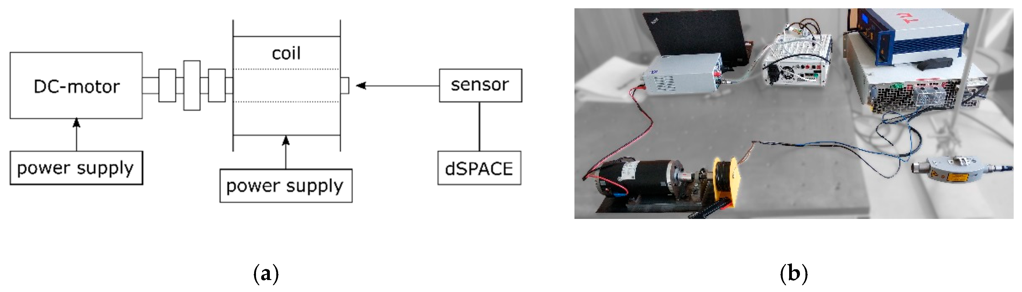
Figure 7.
(a) Schematic of the measurement setup of the test stand and (b) real system.

Figure 8.
Measured displacement at the end of the of the rotating system (a) without switching field and (b) with switching field (sinus 10 Hz).
Figure 8.
Measured displacement at the end of the of the rotating system (a) without switching field and (b) with switching field (sinus 10 Hz).

Figure 9.
Amplitude with increasing rotation speeds: (a) 1000 rpm, (b) 1500 rpm, (c) 2000 rpm.

Figure 10.
Amplitude with increasing current: (a) 0.6 A, (b) 1.0 A, (c) 1.4 A.

Figure 11.
Displacement amplitude with increasing frequency: (a) 10 Hz, (b) 100 Hz, (c) 1000 Hz.


Table 1.
Comparison between piezoelectric and magnetostrictive material [18].
Table 1.
Comparison between piezoelectric and magnetostrictive material [18].
| Magnetostrictive Material (Terfenol-D) | Piezoelectric Material (PXE 52) | |
|---|---|---|
| Maximum strain (10−3 m/m) | … 1.5 | … 1.5 |
| Coupling factor | … 0.75 | … 0.75 |
| Modulus of elasticity (103 N/mm2) | 25 … 35 (cH) 50 … 55 (cB) | ≈110 (cD) 60 … 90 (cE) |
| Speed of sound (m/s) | 1700 () 2500 () | 2800 () 3800 () |
| Energy density (103 J/m3) | 10 … 25 | 20 … 30 |
| Curie temperature (°C) | 380 | 165 … 300 |
| Density (103 kg/m3) | 9.25 | 7.8 |
| Control | current | voltage |
| Field | magnetic field | electric field |
Table 2.
Measurement equipment of all experiments.
| Name of the Equipment | Used for |
|---|---|
| CLV-2534 compact laser vibrometer from Polytec GmbH | Measurement of elongation of the sample |
| Air sensor type K from VOLTCRAFT | Measurement of temperature |
| Magnetic field strength meter FH 52 from MAGNET-PHYSIK Dr. Steingroever GmbH | Measurement of magnetic field |
| MicroLabBox from dSPACE GmbH | Data collection |
| EA-PSI 9750-20 WR 3U from EA Elektro-Automatik GmbH & Co. KG | Power supply coil |
Table 3.
Overview of the experiments.
| Experiment | Frequency/Hz | Amplitude/A | Rotation Speed/rpm | ||||||
|---|---|---|---|---|---|---|---|---|---|
| Influence of rotation speed | 10 | 1.4 | 1000 | 1500 | 2000 | ||||
| Influence of currents amplitude | 10 | 0.6 | 1.0 | 1.4 | 1000 | ||||
| Influence of currents frequency | 10 | 100 | 1000 | 1.4 | 1000 | ||||
© 2020 by the authors. Licensee MDPI, Basel, Switzerland. This article is an open access article distributed under the terms and conditions of the Creative Commons Attribution (CC BY) license (http://creativecommons.org/licenses/by/4.0/).
Share and Cite
MDPI and ACS Style
Titsch, C.; Li, Q.; Kimme, S.; Drossel, W.-G. Proof of Principle of a Rotating Actuator Based on Magnetostrictive Material with Simultaneous Vibration Amplitude. Actuators 2020, 9, 81. https://0-doi-org.brum.beds.ac.uk/10.3390/act9030081
AMA Style
Titsch C, Li Q, Kimme S, Drossel W-G. Proof of Principle of a Rotating Actuator Based on Magnetostrictive Material with Simultaneous Vibration Amplitude. Actuators. 2020; 9(3):81. https://0-doi-org.brum.beds.ac.uk/10.3390/act9030081
Chicago/Turabian StyleTitsch, Christian, Qiang Li, Simon Kimme, and Welf-Guntram Drossel. 2020. "Proof of Principle of a Rotating Actuator Based on Magnetostrictive Material with Simultaneous Vibration Amplitude" Actuators 9, no. 3: 81. https://0-doi-org.brum.beds.ac.uk/10.3390/act9030081
Note that from the first issue of 2016, this journal uses article numbers instead of page numbers. See further details here.