Article

Wireless Walking Paper Robot Driven by Magnetic Polymer Actuator

1
School of Mechanical Engineering, Chonnam National University, Gwangju 61186, Korea
2
Korea Institute of Medical Microrobotics, Gwangju 61011, Korea
3
Robotics Engineering, Chonnam National University, Gwangju 61186, Korea
*
Author to whom correspondence should be addressed.
Submission received: 23 September 2020 / Revised: 25 October 2020 / Accepted: 27 October 2020 / Published: 30 October 2020
(This article belongs to the Special Issue Miniature and Micro-Actuators)

Abstract

:
Untethered small-scale soft robots have been widely researched because they can be employed to perform wireless procedures via natural orifices in the human body, or other minimally invasive operations. Nevertheless, achieving untethered robotic motion remains challenging owing to the lack of an effective wireless actuation mechanism. To overcome this limitation, we propose a magnetically actuated walking soft robot based on paper and a chained magnetic-microparticle-embedded polymer actuator. The magnetic polymer actuator was prepared by combining Fe3O4 magnetic particles (MPs, diameter of ~50 nm) and silicon that are affected by a magnetic field; thereafter, the magnetic properties were quantified to achieve proper force and optimized according to the mass ratio, viscosity, and rotational speed of a spin coater. The fabricated polymer was utilized as a soft robot actuator that can be controlled using an external magnetic field, and paper was employed to construct the robot body with legs to achieve walking motion. To confirm the feasibility of the designed robot, the operating capability of the robot was analyzed through finite element simulation, and a walking experiment was conducted using electromagnetic actuation. The soft robot could be moved by varying the magnetic flux density and on–off state, and it demonstrated a maximum moving speed of 0.77 mm/s. Further studies on the proposed soft walking robot may advance the development of small-scale robots with diagnostic and therapeutic functionalities for application in biomedical fields.

1. Introduction

Small-scale soft robots that do not require an internal power source and energy transmission parts to exhibit movements can be applied in a limited space, such as in the case of biomedical research [1,2]. In addition, unlike conventional large-scale robots that employ bulky actuators and motors [3,4], these robots require small-sized actuators; this serves as motivation for the development of soft robots using various composite polymers and materials. Inspired by the movements of animals and insects in nature, several researchers have developed robots by simulating their motion mechanisms; moreover, they have also studied multi-functional robots with limited and specific structures in varied environments. Recent achievements include milli- and micro-scale robots such as swimming robots [5], crawling robots [6,7], and insect-mimicking robots [8,9]. Particularly, actuators that can be controlled using magnetic field [10,11,12], light [13,14], and heat [15,16] were used to achieve the motion of robots. Furthermore, there are examples of robots whose skeletal structure comprises paper [17,18,19], shape memory alloys [7,20], or polymers [1].
Paper-based robotics research has been introduced for various applications in soft robotics [21,22]. Because paper is inexpensive and easily accessible, it has the benefit of quick and easy fabrication while prototyping. Moreover, paper demonstrates its elastic and plastic deformation properties when folded or unfolded, which is useful to build up joints and links in a robot body. By attaching an actuator and a sensor including an electric circuit, robotic motion can be accomplished. For example, a paper-based actuator that performs a bending or unfolding motion has been developed [23,24], and it has been applied to achieve a gripping motion [25]. Self-folding could be realized by attaching an additional actuator to the paper structure [18]. Furthermore, a wall-climbing robot that employs the elastic energy of paper to achieve a self-folding motion was developed [26]. There are also soft robots that perform deformations or other motions using paper origami structures [17,27,28].
As demonstrated in previous studies, robots based on paper structures mainly exhibit structural folding and bending motions. This requires the attachment of an actuator to the paper, and an electrical signal is generally applied as a stimulation factor via a microcontroller. Such a wired robot has a disadvantage that it can be substantially affected by environmental factors. Particularly, in small-scale soft robots, which are developed for performing technical operations in isolated spaces such as organs, this would lead to critical defects. Notably, robots with a complex structure, such as the origami structure, include a plurality of actuators for operation; therefore, the advantages of inexpensive and reproducible paper materials cannot be maximized.
In this paper, we present a walking soft robot using paper and magnetic polymer actuators that respond to an external magnetic field. The skeleton of the proposed robot was made of paper which can work as folded joints in the robot body. In addition, a polymer based on a mixture of magnetic particles (MPs) and silicon was applied to the actuator part to impart a kinematic change. The walking mechanism of the proposed robot could be controlled through an electromagnetic actuation (EMA) system [29,30,31]. The magneto-responsive movement of the magnetic polymer actuator was transferred to the paper skeleton; consequently, the robotic walking motion was varied by changing the on–off states of the input magnetic field. Finally, the walking motion was realized based on the frictional force with the floor and the elastic force generated at the joint. We optimized the robot structure through kinematical and material characterization of the robot; thus, an analysis of robot motion and speed spectrum with magnetic flux density variation was performed, and structural parameters were obtained. The proposed method has a high reproducibility owing to the cost-effectiveness and simplicity of manufacturing a paper structure; moreover, it has the advantage of active motion control inside an isolated space via the EMA remote control system. In addition, the magnetic polymer actuator does not use an electronic plate that includes coils or a permanent magnet; therefore, it can be applied flexibly in varied environments without being adversely affected by problems such as corrosion.
The remainder of this paper is organized as follows: We have elucidated the design of the paper robot, along with its kinematics and the fabrication of the magnetic polymer actuator, in Section 2. In Section 3, the characteristics and evaluation of the magnetic polymer actuator and the paper material are presented. The robotic motion simulation and experimental results are presented in Section 4. Finally, concluding remarks, along with a discussion of avenues for future work based on the proposed method are presented in Section 5.

2. Materials and Methods

2.1. Design of a Walking Soft Robot

Designing a soft robot based on magnetic polymer actuators is a key issue for establishing an operating mechanism. In this section, we explain the structure of the proposed soft robot and its magnetic field-based walking mechanism. The structure of the proposed robot fundamentally consists of eight axes, as presented in Figure 1a; each joint is connected by eight rigid links. Here, magnetic polymer actuators were attached to links 1, 3, and 7. Further, polymers composed of aligned MPs (Section 2.2) were attached to each link so that a torque could be applied to achieve robot motion.
The operating mechanism of the magnetic polymer consists of two motions according to the on-and-off state of the magnetic field, and the operating state of link 7 is described in Figure 1b. Initially, when the magnetic field is not present, only the normal force ( F N ) due to gravity is maintained. Under the influence of the magnetic field ( B ), the polymer rotates and bends around axis 8 by the magnetic moment ( μ ) caused by the aligned particles and the torque ( τ m ) generated through the interaction of the external magnetic field. After that, the bending polymer generates a recovery torque ( τ r ) according to the elasticity of the paper constituting the structure, which moves the link to the initial position when the magnetic field is turned off, and at the same time causes a driving force for the walking motion. Thus, a motion mechanism based on the magnetic field, gradient, friction force, and elastic force arising from the material of the robot was established, and the kinematic movement and operation mechanism of each link were analyzed.
Forward kinematics were derived for analyzing the robotic motion based on the orientation and position information of the robot link as a function of each joint angle. To derive the kinematics of the proposed walking robot, we used a Denavit–Hartenberg (D–H) matrix that consisted of four parameters: a i 1 , α i 1 , d i , and θ i , which correspond to the link length, link twist, link offset, and joint angle, respectively. Figure 1 depicts the geometric structure of the soft robot and coordinate frame assignment.
The D–H convention matrix is shown in Equation (1).
T i i 1 = [ cos θ i c o s α i 1 s i n θ i s i n α i 1 s i n θ i a i 1 c o s θ i s i n θ i c o s α i 1 c o s θ i s i n α i 1 c o s θ i a i 1 s i n θ i 0 s i n α i 1 c o s α i 1 d i 0 0 0 1 ]
The proposed robot mechanism is actuated by varying the joint angle for the given length of the link. Therefore, the values of constants α i 1 and d i in matrix T i i 1 correspond to zero, whereas the parameters a i 1 for a link length and θ i for a revolute joint are constant and variable, respectively. The D–H parameters are listed in Table 1. These values were set within the variable range, assuming that force is applied to links 1, 3, and 7 as in Figure 1a; further, they were used to determine the movability of the walking mechanism.
Using (1) and the D–H parameters, the T i i 1 matrices of each joint could be derived. Moreover, we can obtain the individual transformation matrices T 1 0 T 8 7 and the global transformation matrices T L n 0 via (2).
T L n R =   T L 1 R   T L 2 L 1   T L 3 L 2   T L n L n 1
Furthermore, by using the T L n 0 matrices, the position of links that comprise the robot could be determined. We examined the walking motion according to the change in the link position using the derived kinematic model. Consequently, the simulated motions are depicted in Figure 2, with respect to the joint angle varying. Position 1 represents the applied initial condition, and motions 2 and 3 represent the cases of applying the medium and maximum deflection states, respectively. This shows that, if a torque that is sufficient to cause a change in the parameters listed in Table 1 can be applied to each link, a contraction motion could be realized for the elastic propulsion of a paper robot. Moreover, in position 3, in the absence of magnetic field, the contracted soft robot moves forward owing to the torque generated by the elastic force of the paper and friction.
The initial design confirmed through forward kinematics is to examine the operability of the robot. As mentioned above, the designed robot realizes motion by the interaction of forces transmitted to the link, and structurally, the length of the link acts as the most fatal factor to the motion. Intuitively, links 1 to 3 are parts for promoting the working motion, 6 to 8 are parts to support the motion that will occur during movement, and link 5 is a part that organically connects these two roles. In detail, the length of the 3rd link (position 3 in Figure 2) should be long enough to induce torque by tilting the second link forward, so that when the magnetic field is removed, links 1 and 2 are pushed forward. The length of link 7 should be designed to provide the torque and friction force that will cause the robot to take the squat motion. If links 1, 3, and 7 are too short and do not bend properly in the gravitational direction, a problem may arise in generating a force interaction for propulsion. Therefore, it was considered that the designed robot maintains the complementary mechanical form of the link for taking motion, and the process of detailed calibration of this through simulation and experiment was carried out in Section 4.1.

2.2. Magnetic Polymer Actuator Materials

The skeleton structure and working components of the soft robot were constructed using paper and the aforementioned polymer actuator. Here, because the magnetic polymer acts as an actuator that imparts force to the soft robot, the materials contained in the polymer composite should be characterized. For magnetic polymer fabrication, Fe3O4 (diameter of ~50 nm) and Ecoflex 00-30 were purchased from Sigma-Aldrich (St. Louis, USA) and Smooth-On Inc. (Macungie, USA), respectively. Fe3O4 was selected for its biocompatibility because of it has a relatively low toxicity compared to other MPs. A polymer obtained by spin coating Ecoflex 00-30 silicon containing a specific ratio of Fe3O4 was prepared, and inspection was performed via scanning electron microscopy (SEM, SU-8000) to confirm its morphology and surface condition. Using an EMA system and vibrating sample magnetometer (VSM, lake shore 7400 series), the reaction and motion test of magnetic polymer actuator was performed.

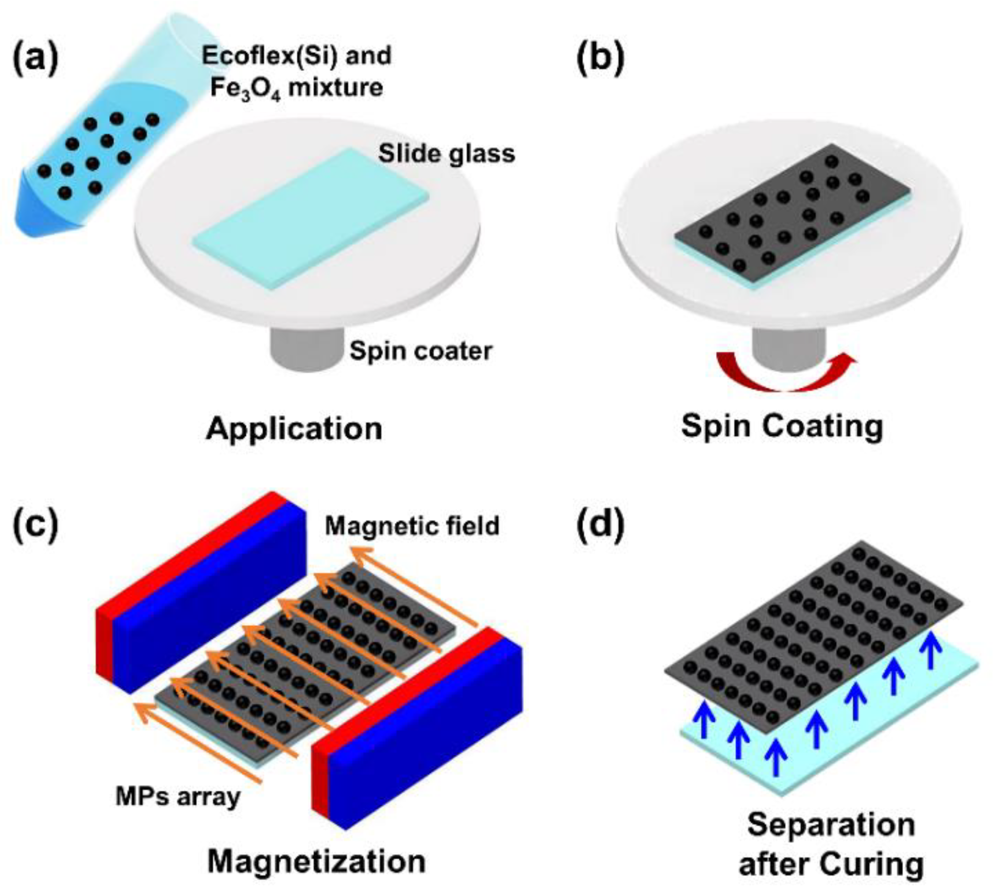
2.3. Fabrication of Magnetic Polymer Actuator

The magnetic polymer actuator is composed of Fe3O4 as the magnetic particle and Ecoflex 00-30 silicon. As depicted in Figure 3, to obtain the polymer solution, fabrication proceeded in the following order. Firstly, the silicon subject and the curing agent were slowly stirred in the ratio 1:1 to prevent air bubbles. In the case of using Ecoflex 00-20, it caused lower tensile strength than Ecoflex 00-30 (200 psi), and there was no difference in mixing viscosity (3000 cps), specific gravity (1.07 g/cc), and volume (26 in/lb). Thereafter, Fe3O4 was mixed with Ecoflex 00-30 at 20, 30, and 40 wt% to prepare a solution of the polymer and applied onto a slide glass (Figure 3a). The sample was spin-coated at 600 and 800 rpm to obtain the desired thickness (Figure 3b). For magnetization, a sample was placed between permanent magnets (neodymium, 50 × 25 × 10 mm), as shown in Figure 3c. Here, the north pole of one magnet was oriented to face the south pole of the other, and the two magnets were set at a distance of 70 mm from one another. The sample was exposed to a magnetic field for 1 min to form an alignment through the magnetization of the internal MPs. At this time, the magnetic field was formed in the horizontal direction along with the permanent magnet placement, and the direction of MPs’ arrangement coincided with the permanent magnet. Finally, the magnetic polymer fabrication was complete when the sample separated from the slide glass after curing (Figure 3d).

3. Characterization

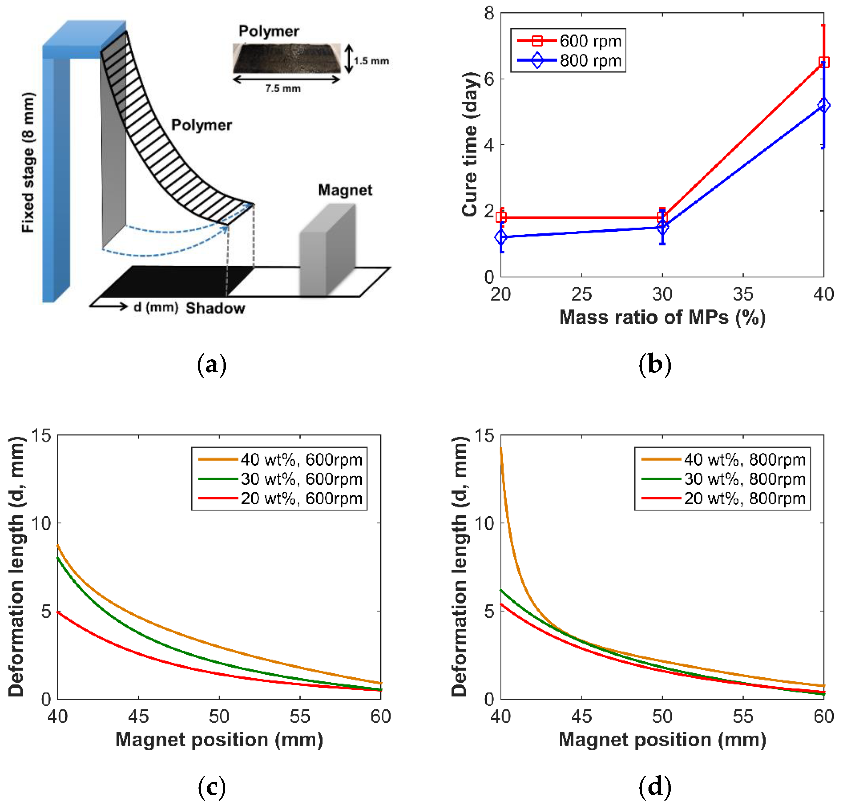
3.1. Magnetic Polymer Actuator
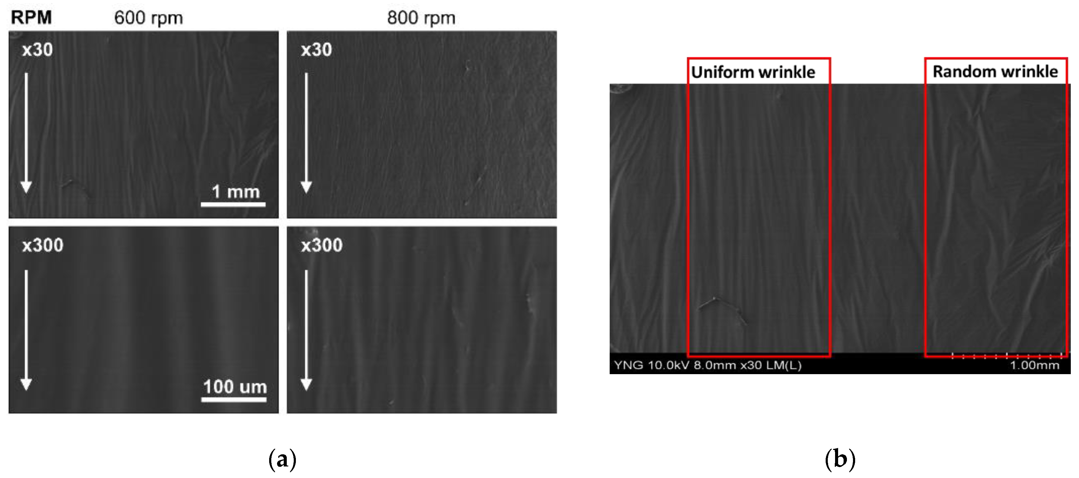
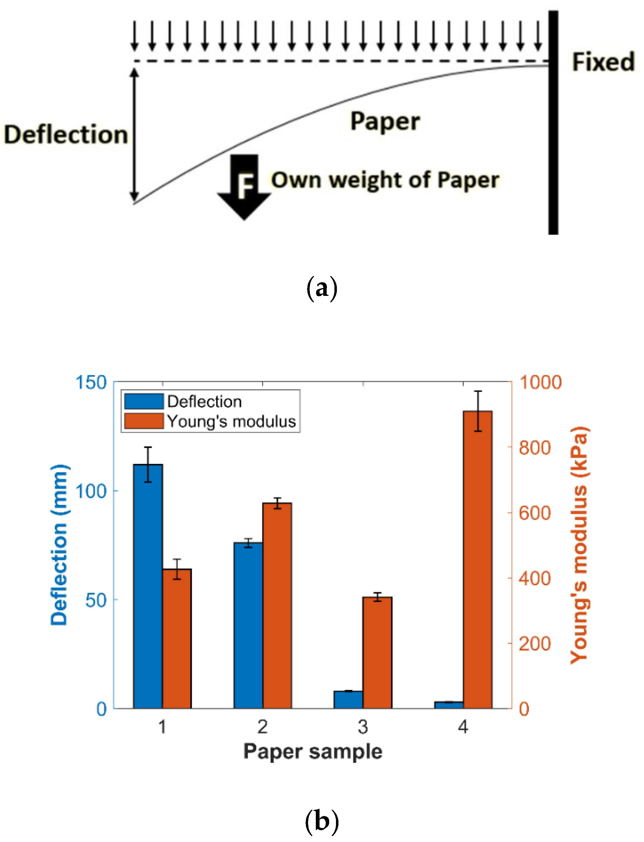
To evaluate the reactivity of the fabricated magnetic polymer, property tests were conducted in terms of two parameters: (1) the magnetic content of the polymer actuator; (2) the distance from a permanent magnet. Taking this into consideration, the test proceeded by attaching the polymer edge to a fixed stage to react only through bending and compared the displacement of the changing shadow while moving the position of the permanent magnet (Figure 4a). Polymers prepared for characterization consisted of 20, 30, and 40 wt%. Here, if the content of the MPs is increased to 50 wt% or more, the remanence magnetization increases in the fabrication step 3 (Figure 3b), adversely affecting the magnetic particle chain that should be parallel to the magnetic field, and reducing the magnetic field reactivity [2]. By changing the mixing ratio of the Fe3O4 solution and the number of spins, the test was repeated five times with every new polymer sample for statistics [32]. As a result, the composition ratio of Fe3O4 in the polymer was higher, the deflection according to the magnetic field becomes higher, as provided in Figure 4c,d, where each graph is polynomial curve-fitting data and contains an error of up to 0.5 mm at 600 rpm and up to 1 mm at 800 rpm. From the data, it was confirmed that the deflection at 600 rpm recorded a higher value on average, and that there was a section in which a 40 wt% polymer change rapidly occurred when the permanent magnet was placed within 45 mm at 800 rpm. This is considered to be caused by the decrease in the polymer thickness due to the high rotational speed during the spin coating step. Additionally, for each variable, the cure time of the polymer on average required 1.5 days at 20 wt%, 1.5 days at 30 wt%, and 6 days at 40 wt% (Figure 4b). Based on this, a polymer with a higher reactivity and a shorter cure time with 30 wt% was selected for the polymer actuator.
The surface of each polymer was photographed using SEM to precisely observe the polymer morphology and the result of the MPs’ alignment with respect to the number of coating revolutions. Figure 5 is an enlarged view of the polymer surface produced by the proposed fabrication method. The left figure is the result of using a 30 wt% solution of Fe3O4 and 600 rpm, and the right side is the result of spin coating at 800 rpm. The two pictures above are images of 30 times the polymer surface at each spin coating speed, and the pictures below are 300 times enlarged. Through the SEM images, we judged that there is a uniformity of MPs application through comparison of each spin coating speed and polymer surface state, and we then examined the chain structure in which the difference occurs depending on the applied rotation speed. The wrinkled lines were caused by the shrinkage of the polymer in the curing step, corresponding to Figure 4d. During curing step, both crosslinking of the polymer and evaporation of the solvent caused a shrinkage in the volume of the polymer, further causing the fixed MPs to form a wrinkled structure. The equilibrium wrinkles in the chained samples indicate that the particles in the film are well aligned, and in the unchained samples randomly wrinkled structures are observed. Considering that the directions of the formed wrinkled lines and the left arrow are the same, it was confirmed that the MPs are aligned in the direction of the magnetic field. In addition, the polymer applied with 800 rpm had more wrinkles than that applied with 600 rpm, which was judged by the influence of more evenly distributed MPs at high number of revolutions. However, at the ×30 ratio, it is possible to find a randomly wrinkled section to the right of the section of 600 rpm and 800 rpm. This is the case where MPs are located outside the section where the magnetic field is formed horizontally by the permanent magnet, and the polymer actuator is used as a section in which the uniform alignment is formed. So far, the characterization of the magnetic polymer has been analyzed and appropriate component values have been set.

3.2. Paper Property

It is necessary to present the numerical properties of the paper to specify the characteristics of the paper-based robot and confirm its movability in response to an external magnetic field. The paper density, yield strength and Poisson ratio of the utilized standard office copy paper were 1200 kg/m3, 33.65 Pa, and 0.27, which are calibrated by simulation. Moreover, the Young’s modulus was calculated by using a uniformly loaded cantilever deflection equation.
E = w L 4 / 8 I δ
where w , and L are the uniform load and length of the beam, I is an area moment of inertia, and δ is the maximum deflection. For deriving each parameter, we conducted a simple experiment using four paper samples of different sizes. Table 2 includes the parameters of paper samples used for measuring the deflection in each test.
The test for Young’s modulus examination was implemented by the experimental setup depicted in Figure 6a. After using 3 mm of length for fixing, the deflection for the intrinsic weight of each sample was measured. This was measured for five times each through the camera, and the averaged results are presented in Figure 6b along with the calculated value of Young’s modulus. When compared with the actual paper Young’s modulus value, the calculated value has an error depending on the paper sample size and measurement scale. Even if the deflection of the sample is small, a relatively low Young’s modulus may have been calculated by the result derived from the set value, such as the term to the power of 4 of the length. So, we applied the Young’s modulus as an average of 577 kPa for subsequent simulations. These characterized values were used to verify the movement of the walking robot.

4. Simulation and Experiments

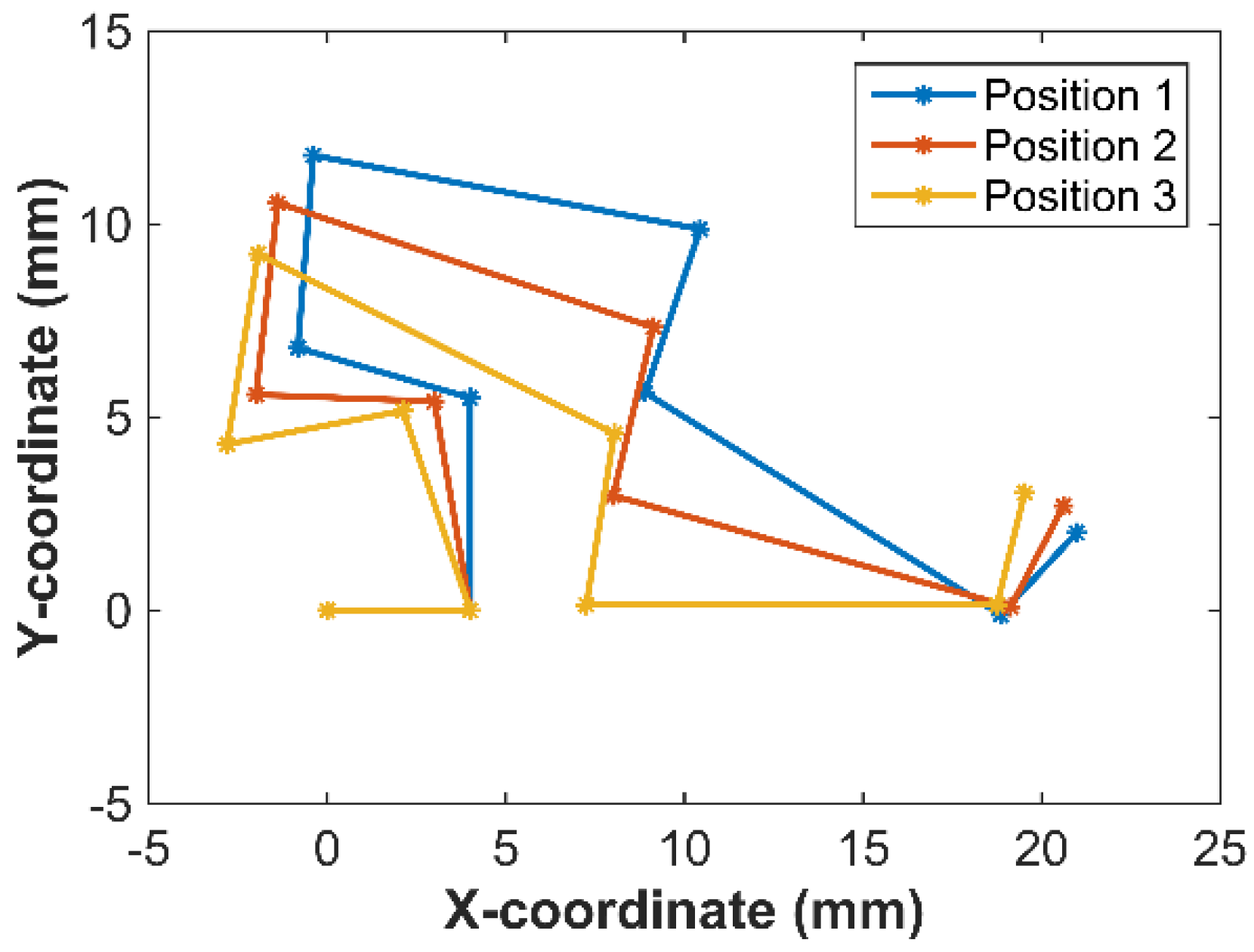
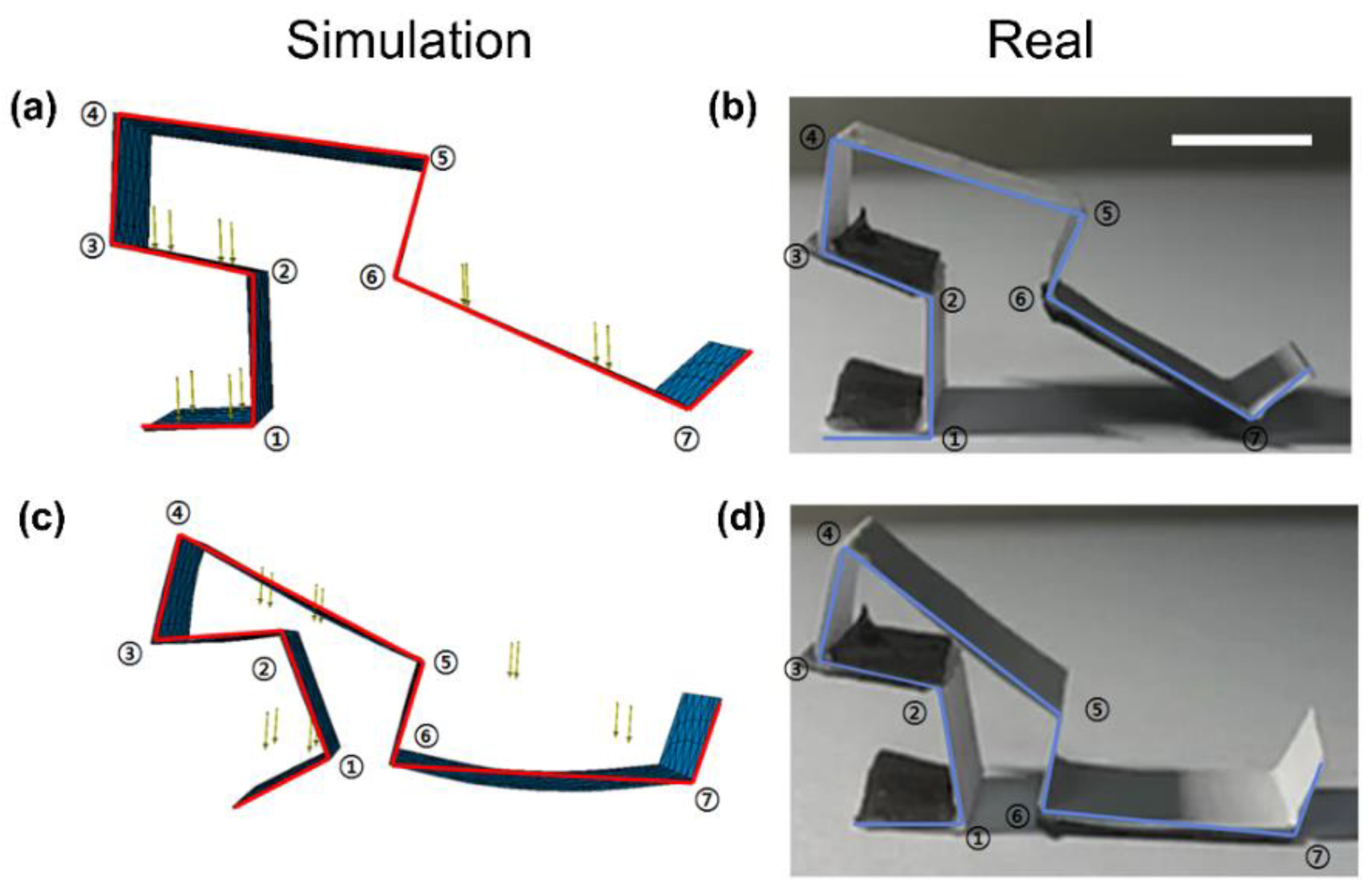
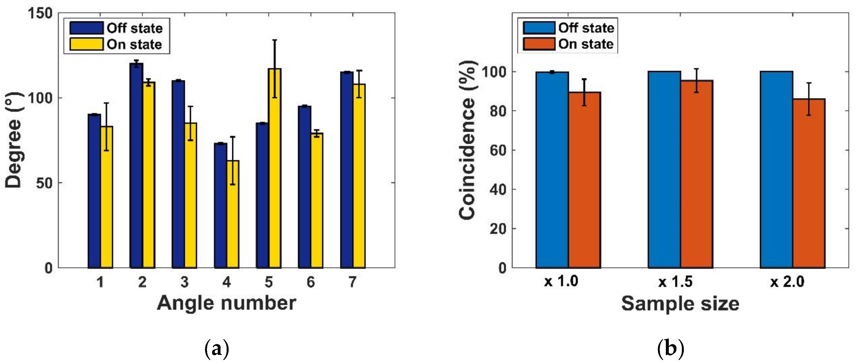
4.1. Robot Motion Simulation

For the verification of whether the paper-based soft robot can execute the motion as depicted in Figure 2, a numerical simulation was performed through the finite element method. The simulation parameters were obtained through the physical properties of the paper constituting the soft robot and the characterization results detailed in Section 3. In which, to minimize the numerical inaccuracy of the alignment of MPs and the physical properties of the polymer actuator, the force due to polymer bending was assumed to be the same as the input force to produce robot joint torque in the presence of a magnetic field. For this, the actual value of the bending force is obtained by the displacement measurement after attaching the polymer to the spring under the on and off states of the magnetic fields. The bending force at the time of applying a magnetic field was derived according to the spring constant. Finally, the force (36.805 N/g) generated per 1 g of unit mass was derived through the weight of the polymer. As with the assumptions mentioned, we applied this force value acting on a polymer actuator in a soft robot model and performed a simulation. The appearance before and after the effect of the magnetic field was analyzed and is presented in Figure 7.
The proposed mechanism used a method of moving forward through the elastic force generated by a paper material with switching from the on-state of the magnetic field to the off-state and the frictional force at the links numbered from one to seven in Figure 7. Based on this, we compared the behavior of the soft robot through simulations and experiments, considering the case of the presence and absence of the magnetic field. In cases where there was no magnetic field, the software robot maintained its initial state as in Figure 7a. Each link maintained a stable state without the influence of external forces other than gravity. Here, when a magnetic field was formed, a bending force was formed in links one, three, and seven, and each link crouched and turned into a shape to move forward. Figure 7c shows the appearance of the soft robot affected by the magnetic field. When a bending force was applied, joints number one to four contracted up to 25° while joint five expanded up to 30°. The robot pulled seven and eight links into a squat motion, and the paper links formed a torque-induced appearance. Thereafter, when the robot switched to the off mode, a clockwise torque occurred, and joint two, three, and four quickly expanded because of the frictional force between links seven and eight, and the floor; thus, the appearance of the robot when it took a step could be predicted.
Subsequently, the reliability of the numerical simulation was verified by comparing each joint change with real robot motions depicted in Figure 7b,d. Prior to comparison, the joints between two adjacent links were numbered and defined as joined in Figure 7, and the numbered angles according to the change in the on–off state of the magnetic field are summarized in Figure 8a. The bars in the graph represent the simulation values, and the error bars represent the error from the experimental values. The soft robot in the off-state was affected only by gravity and exhibited almost the same result as the experimental value; in the on-state, it achieved a coincidence rate of more than 89% on an average. In addition, the simulation results of the soft robots scaled to 1.5 and 2 times also exhibited an average of 95.4% and 86% coincidence when affected by a magnetic field (Figure 8b). Based on this, we predicted the driving mechanism of the model and performed a size standardization and walking experiment of the walking soft robot.

4.2. Experimental Setup

The EMA system was used for the driving experiment of the walking soft robot. This system consists of a pair of Maxwell coils, a Helmholtz coil, and four rectangular coils, [32,33]. The fabricated soft robot was located in the region of interest for controlling motion. For the behavior of the soft robot, a uniform magnetic field was applied horizontally, and torque (τ) was generated by the elasticity of the paper, τ = V M × B , where   B = [ B x   B y   B z ] T , V , and M = [ m x   m y   m z ] T are the magnetic flux, the volume of the object, and magnetization vector of magnetic device [2]. In addition, it was necessary to form a higher intensity uniform magnetic field in order to achieve the desired operation and speed of various sized robots. For this reason, a VSM (vibrating sample magnetometer, lake shore 7400 series) device was used for generating a larger magnetic field, and the driving efficiency and speed of the soft robot were compared and analyzed based on the change in magnetic field strength of up to 1 T. The on–off control method was operated with a frequency of 2 Hz giving the paper polymer deposits enough time to react to the magnetic field. The experiment was conducted by changing the magnitude of the magnetic field and input signal frequency using the EMA system; soft robots of different sizes were used for the analysis.

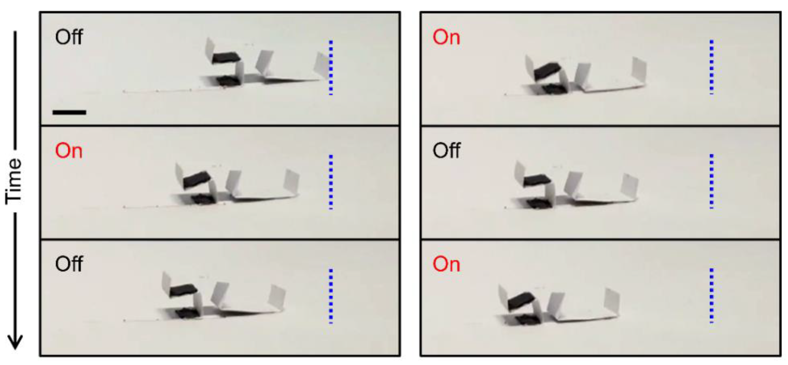
4.3. Experimental Results

Figure 9 shows the moving motion over time using a soft robot that was scaled 1.5 times with the highest matching rate in the simulation. We captured every 5 s in the crouched (on) and return (off) states to verify the walking mechanism. When the magnetic field was activated, the soft robot exhibited a shape that curled and contracted while pulling the back leg. Thereafter, along with the removal of the magnetic field, the friction of the back leg suppressed the backwards motion and initiated the forwards motion. Finally, the continuous on–off control of the magnetic field realized the positional movement.
We measured the moving distance and the time taken by the soft robot and accurately calculated the walking velocity according to the structural scale size and magnetic flux density. In order to increase the magnitude of magnetic flux density, experiments were conducted using a VSM device. A uniform magnetic field of maximum 1 T was applied under the same conditions as before. The moving distance was equally applied up to 3 cm, and the elapsed time was measured 10 times for each case. Under the assumption that the walking velocity had a constant value, the velocity in each case was calculated by dividing the travel distance by time. Figure 10 shows the averaged velocity calculated by the experiment according to the abovementioned two variables. The higher flux density increased the velocity, whereas the larger size decreased the velocity. With a magnetic field of 0.649 T and a soft robot with a scale of 1.25 times, a maximum speed of 77 mm/s was achieved. However, in the magnetic field below 0.5 T, the weight of the soft robot had a fatal effect, and it was judged that the generated torque was insufficient to realize the motions of pushing and pulling the paper link. This can be solved by performing studies that would consider the force in motion and develop structures that effectively transmit energy. A material with better resilience could also be used.

5. Conclusions

In this study, we proposed and validated a walking soft robot mechanism made of a paper, actuated by a polymer actuator embedded with chained MPs. Magnetic polymers in which MPs are aligned has the property of aligning according to the direction of a uniform magnetic field, and a torque mechanism to generate walking motion was used. The feasibility of the proposed mechanism was examined via robot kinematics and simulation. The proposed soft robot was fabricated in the frame of a paper body and operated by the on and off states of magnetic field control via the EMA system and a VSM for successful motion. The EMA system was useful for controllability such as changes in the direction of the magnetic field, but there was a limit to completely solving the stiffness of the paper with the torque generated by the polymer. Accordingly, a high-intensity magnetic field of up to 1 T was applied using the VSM, and analysis was conducted according to the robot size and walking speed. The devised mechanism was verified, and the performance was evaluated for various sizes of soft robots and a speed control of up to 0.77 mm/s was achieved.
The fabricated magnetic polymer actuator and the paper framework played an important role in realizing a new mechanism for soft walking robots. The proposed soft robot mechanism focuses only on walking motion and its actuation through magnetic polymer actuator; however, to implement a multi-functional small-scale robot, higher degrees of freedom motion and a method for their independent actuation control needs to be conquered. In addition to this, further technical developments including robot joint angle measurements and robot posture sensing, as well as advanced control methods in utilizing active electromagnetic field control are still needed for ensuring the smooth movement of the robot. Although we conducted the robot simulation to verify the motion of the designed robot configuration, the lack of dynamic behavior incorporating the polymer actuator properties needs to be further established to predict the newly designed robot motion before fabrication. Nevertheless, we think that the development of articulated robots through partial actuators suggests a new research direction in the context of recent changes to the polymer model, or in a situation in which soft robots, produced by themselves, are being studied in various fields with improved mechanisms and driving circuits [34,35]. In the future, it is expected that small-scale robots that perform various functionalities in addition to walking will be utilized in various applications such as drug delivery and biopsy in restricted and inaccessible environments within the human body.

Author Contributions

Conceptualization, C.-S.K.; methodology, Y.-U.J., I.-S.L., J.-Y.J., and M.C.H.; software, Y.-U.J., I.-S.L., J.-Y.J., and M.C.H.; validation, H.-S.L. and E.C.; investigation, H.-S.L.; data curation, Y.-U.J., I.-S.L., and J.-Y.J.; writing—original draft preparation, H.-S.L.; writing—review and editing, A.H. and C.-S.K.; visualization, H.-S.L.; supervision, C.-S.K.; funding acquisition, J.-O.P. All authors have read and agreed to the published version of the manuscript.

Funding

This research was supported by a grant of the Korea Health Technology Development R&D Project through the Korea Health Industry Development Institute (KHIDI), funded by the Ministry of Health and Welfare, Republic of Korea (grant number: HI19C0642).

Acknowledgments

We would like to thank anonymous reviewers’ valuable comments and helpful discussions to improve the quality of the paper.

Conflicts of Interest

The authors declare no conflict of interest.

References

  1. Hu, W.; Lum, G.Z.; Mastrangeli, M.; Sitti, M. Small-scale soft-bodied robot with multimodal locomotion. Nature 2018, 554, 81–85. [Google Scholar] [CrossRef] [PubMed]
  2. Ijaz, S.; Li, H.; Hoang, M.C.; Kim, C.S.; Bang, D.; Choi, E.; Park, J.O. Magnetically actuated miniature walking soft robot based on chained magnetic microparticles-embedded elastomer. Sens. Actuators A Phys. 2020, 301, 111707. [Google Scholar] [CrossRef]
  3. Lee, H.D.; Moon, J.I.; Kang, T.H. Design of a series elastic tendon actuator based on gait analysis for a walking assistance exosuit. Int. J. Control. Autom. Syst. 2019, 17, 2940–2947. [Google Scholar] [CrossRef]
  4. Yazdani, M.; Salarieh, H.; Foumani, M.S. Bio-inspired decentralized architecture for walking of a 5-link biped robot with compliant knee joints. Int. J. Control. Autom. Syst. 2018, 16, 2935–2947. [Google Scholar] [CrossRef]
  5. Ren, Z.; Hu, W.; Dong, X.; Sitti, M. Multi-functional soft-bodied jellyfish-like swimming. Nat. Commun. 2019, 10, 1–12. [Google Scholar] [CrossRef] [PubMed]
  6. Shepherd, R.F.; Ilievski, F.; Choi, W.; Morin, S.A.; Stokes, A.A.; Mazzeo, A.D.; Whitesides, G.M. Multigait soft robot. Proc. Natl. Acad. Sci. USA 2011, 108, 20400–20403. [Google Scholar] [CrossRef] [Green Version]
  7. Yuk, H.; Kim, D.; Lee, H.; Jo, S.; Shin, J.H. Shape memory alloy-based small crawling robots inspired by C. elegans. Bioinspir. Biomim. 2011, 6, 046002. [Google Scholar] [CrossRef]
  8. Wu, Y.; Yim, J.K.; Liang, J.; Shao, Z.; Qi, M.; Zhong, J.; Fearing, R.S. Insect-scale fast moving and ultrarobust soft robot. Sci. Robot. 2019, 4, eaax1594. [Google Scholar] [CrossRef] [Green Version]
  9. Joyee, E.B.; Pan, Y. Multi-material additive manufacturing of functional soft robot. Procedia Manuf. 2019, 34, 566–573. [Google Scholar] [CrossRef]
  10. Gray, B.L. A review of magnetic composite polymers applied to microfluidic devices. J. Electrochem. Soc. 2014, 161, B3173. [Google Scholar] [CrossRef]
  11. Venkiteswaran, V.K.; Samaniego, L.F.P.; Sikorski, J.; Misra, S. Bio-inspired terrestrial motion of magnetic soft millirobots. IEEE Robot. Autom. Lett. 2019, 4, 1753–1759. [Google Scholar] [CrossRef] [Green Version]
  12. Maeda, K.; Shinoda, H.; Tsumori, F. Miniaturization of worm-type soft robot actuated by magnetic field. Jpn. J. Appl. Phys. 2020, 59, SIIL04. [Google Scholar] [CrossRef]
  13. Rogóż, M.; Zeng, H.; Xuan, C.; Wiersma, D.S.; Wasylczyk, P. Light-driven soft robot mimics caterpillar locomotion in natural scale. Adv. Opt. Mater. 2016, 4, 1689–1694. [Google Scholar] [CrossRef]
  14. Pilz da Cunha, M.; Ambergen, S.; Debije, M.G.; Homburg, E.F.; den Toonder, J.M.; Schenning, A.P. A Soft Transporter Robot Fueled by Light. Adv. Sci. 2020, 7, 1902842. [Google Scholar] [CrossRef] [PubMed] [Green Version]
  15. Cheng, N.; Ishigami, G.; Hawthorne, S.; Chen, H.; Hansen, M.; Telleria, M.; Iagnemma, K. Design and analysis of a soft mobile robot composed of multiple thermally activated joints driven by a single actuator. In Proceedings of the 2010 IEEE International Conference on Robotics and Automation, Anchorage, AK, USA, 3–7 May 2010; pp. 5207–5212. [Google Scholar]
  16. Go, G.; Jin, Z.; Park, J.O.; Park, S. A Thermo-electromagnetically actuated microrobot for the targeted transport of therapeutic agents. Int. J. Control. Autom. Syst. 2018, 16, 1341–1354. [Google Scholar] [CrossRef]
  17. Shigemune, H.; Maeda, S.; Hara, Y.; Hosoya, N.; Hashimoto, S. Origami robot: A self-folding paper robot with an electrothermal actuator created by printing. IEEE/ASME Trans. Mechatron. 2016, 21, 2746–2754. [Google Scholar] [CrossRef]
  18. Shigemune, H.; Maeda, S.; Cacucciolo, V.; Iwata, Y.; Iwase, E.; Hashimoto, S.; Sugano, S. Printed paper robot driven by electrostatic actuator. IEEE Robot. Autom. Lett. 2017, 2, 1001–1007. [Google Scholar] [CrossRef]
  19. Han, D.D.; Zhang, Y.L.; Jiang, H.B.; Xia, H.; Feng, J.; Chen, Q.D.; Sun, H.B. Moisture-responsive graphene paper prepared by self-controlled photoreduction. Adv. Mater. 2015, 27, 332–338. [Google Scholar] [CrossRef]
  20. Huang, W.; Huang, X.; Majidi, C.; Jawed, M.K. Dynamic simulation of articulated soft robots. Nat. Commun. 2020, 11, 1–9. [Google Scholar] [CrossRef]
  21. Martinez, R.V.; Fish, C.R.; Chen, X.; Whitesides, G.M. Elastomeric origami: Programmable paper-elastomer composites as pneumatic actuators. Adv. Funct. Mater. 2012, 22, 1376–1384. [Google Scholar] [CrossRef]
  22. Hamedi, M.M.; Campbell, V.E.; Rothemund, P.; Güder, F.; Christodouleas, D.C.; Bloch, J.F.; Whitesides, G.M. Electrically activated paper actuators. Adv. Funct. Mater. 2016, 26, 2446–2453. [Google Scholar] [CrossRef]
  23. Amjadi, M.; Sitti, M. High-performance multiresponsive paper actuators. ACS Nano 2016, 10, 10202–10210. [Google Scholar] [CrossRef] [PubMed]
  24. Wang, G.; Cheng, T.; Do, Y.; Yang, H.; Tao, Y.; Gu, J.; Yao, L. Printed paper actuator: A low-cost reversible actuation and sensing method for shape changing interfaces. In Proceedings of the 2018 CHI Conference on Human Factors in Computing Systems, Montreal, QC, Canada, 21–26 April 2018; pp. 1–12. [Google Scholar]
  25. Ryu, J.; Mohammadifar, M.; Tahernia, M.; Chun, H.I.; Gao, Y.; Choi, S. Paper Robotics: Self-Folding, Gripping, and Locomotion. Adv. Mater. Technol. 2020, 5, 1901054. [Google Scholar] [CrossRef]
  26. Wu, Q.; Pradeep, V.; Liu, X. A paper-based wall-climbing robot enabled by electrostatic adhesion. In Proceedings of the 2018 IEEE International Conference on Soft Robotics (RoboSoft), Livorno, Italy, 24–28 April 2018; pp. 315–320. [Google Scholar]
  27. Shigemune, H.; Maeda, S.; Hara, Y.; Koike, U.; Hashimoto, S. Kirigami robot: Making paper robot using desktop cutting plotter and inkjet printer. In Proceedings of the 2015 IEEE/RSJ International Conference on Intelligent Robots and Systems (IROS), Hamburg, Germany, 28 September–2 October 2015; pp. 1091–1096. [Google Scholar]
  28. Li, J.; Godaba, H.; Zhang, Z.Q.; Foo, C.C.; Zhu, J. A soft active origami robot. Extrem. Mech. Lett. 2018, 24, 30–37. [Google Scholar] [CrossRef]
  29. Nguyen, K.T.; Hoang, M.C.; Go, G.; Kang, B.; Choi, E.; Park, J.O.; Kim, C.S. Regularization-based independent control of an external electromagnetic actuator to avoid singularity in the spatial manipulation of a microrobot. Control Eng. Pract. 2020, 97, 104340. [Google Scholar] [CrossRef]
  30. Hoang, M.C.; Nguyen, K.T.; Le, V.H.; Kim, J.; Choi, E.; Kang, B.; Park, J.O.; Kim, C.S. Independent Electromagnetic Field Control for Practical Approach to Actively Locomotive Wireless Capsule Endoscope. IEEE Trans. Syst. MAN, Cybern. Syst. 2019, 99, 1–13. [Google Scholar] [CrossRef]
  31. Kim, J.; Nguyen, P.B.; Kang, B.; Choi, E.; Park, J.O.; Kim, C.S. A novel tip-positioning control of a magnetically steerable guidewire in sharply curved blood vessel for percutaneous coronary intervention. Int. J. Control. Autom. Syst. 2019, 17, 2069–2082. [Google Scholar] [CrossRef]
  32. Liu, J.A.C.; Gillen, J.H.; Mishra, S.R.; Evans, B.A.; Tracy, J.B. Photothermally and magnetically controlled reconfiguration of polymer composites for soft robotics. Sci. Adv. 2019, 5, eaaw2897. [Google Scholar] [CrossRef] [Green Version]
  33. Hoang, M.C.; Le, V.H.; Kim, J.; Choi, E.; Kang, B.; Park, J.O.; Kim, C.S. Intestinal Tattooing Mechanism Integrated with Active Wireless Capsule Endoscope. In Proceedings of the 2018 7th IEEE International Conference on Biomedical Robotics and Biomechatronics (Biorob), Enschede, The Netherlands, 26–29 August 2018; pp. 1254–1259. [Google Scholar]
  34. Wang, X.; Mao, G.; Ge, J.; Drack, M.; Bermúdez, G.S.C.; Wirthl, D.; Lling, R.; Kosub, T.; Bischoff, L.; Fassbender, J. Untethered and ultrafast soft-bodied robots. Commun. Mater. 2020, 1, 1–10. [Google Scholar] [CrossRef]
  35. Zhao, J.; Zhang, J.; McCoul, D.; Hao, Z.; Wang, S.; Wang, X.; Sun, L. Soft and fast hopping–running robot with speed of six times its body length per second. Soft Robot. 2019, 6, 713–721. [Google Scholar] [CrossRef]
Figure 1. (a) Kinematic representation of the proposed walking soft robot; coordinate definition and geometric discretization of the robot. Blue axis means x-coordinates, other axes mean y-, z-coordinates. Black planes are where the magnetic polymers are attached, and red arrows are the normal force of the robot. (b) Schematic diagram of the of torque generation mechanism using magnetic polymer and magnetic field alignment. ( τ : Torque, μ : Magnetic moment of MPs, B : Magnetic field).
Actuators 09 00109 g001
Figure 2. Forward kinematics simulation representing the link position with joint angle variation.
Actuators 09 00109 g002
Figure 3. Schematic of the fabrication outline of a polymer actuator based on chained-magnetic-particle-embedded elastomer. (a) A composite was applied to the slide glass. (b) Samples were spin coated. (c) By exposing the silicon mixture to the placed permanent magnet, an array was formed by the magnetization of MPs inside. (d) After curing, the sample was separated from the slide glass.
Actuators 09 00109 g003
Figure 4. (a) Illustration of the test for characterizing the fabricated magnetic polymer. (b) Cure time according to the mass ratio of MPs of silicon. (c,d) Result of the difference in the shadow length with respect to the magnet position when spin coating speeds of (c) 600 rpm and (d) 800 rpm are applied.
Actuators 09 00109 g004
Figure 5. SEM images of magnetic polymer: (a) with 600 (left) and 800 (right) rpm spin coating speed (Magnetic polymer: 30 wt%). Arrows indicate the magnetic field direction by two permanent magnets, (b) uniform wrinkle and random wrinkle comparison.
Actuators 09 00109 g005
Figure 6. Characterization of Young’s modulus using deflection measurement. (a) Schematic images of paper deflection test. (b) Deflection measurement value and calculated value of Young’s modulus according to the paper sample.
Actuators 09 00109 g006
Figure 7. Numerical simulation and actual behavior. (ad) The appearance of the soft robot when (a,b) there is no magnetic field and (c,d) there is magnetic field of 0.5 T. (Scale bar: 5 mm).
Actuators 09 00109 g007
Figure 8. Comparison of angles between joint points of the walking soft robot. (a) Joint angle compression result at ×1.0 scale (b) Simulation coincidence rate with respect to the sample size.
Actuators 09 00109 g008
Figure 9. Snapshots of walking soft robot motion. A photograph of the robot’s walking motion experiment taken in chronological order. (Blue line: start line, scale bar: 5 mm).
Actuators 09 00109 g009
Figure 10. Result of the walking velocity experiment conducted according to the magnetic flux density and varying size of the soft robot.
Actuators 09 00109 g010
Table 1. Denavit–Hartenberg (D–H) parameters of a walking soft robot.
Link # Link   Length   ( l i ) Initial   Joint   Angle   ( θ i ) Joint   Angle   ( θ j )
14
25.590°90° < θ 2 < 110°
3575°75° < θ 3 < 80°
45−80°−110° < θ 4 < −80°
511−95°−105° < θ 5 < −95°
64.5−100°−100° < θ 6 < −75°
711.580°85° < θ 7 < 100°
8375°75°
Table 2. Parameters of paper samples.
Paper Sample Paper   Size   ( m m × m m ) Length
(L, mm)
Width
(b, mm)
Thickness   ( h ,   m m )
1105 × 148.5102148.50.13
2105 × 74.2510274.250.13
352.5 × 74.2549.574.250.13
452. 5 × 37.12549.537.1250.13
Publisher’s Note: MDPI stays neutral with regard to jurisdictional claims in published maps and institutional affiliations.

