
Energy System Optimization and Simulation for Low-Altitude Solar-Powered Unmanned Aerial Vehicles


1
National Key Laboratory of Human Machine and Environment Engineering, School of Aeronautical Science and Engineering, Beihang University, Beijing 100191, China
2
School of Chemical and Process Engineering, University of Leeds, Leeds LS2 9JT, UK
*
Authors to whom correspondence should be addressed.
Aerospace 2022, 9(6), 331; https://0-doi-org.brum.beds.ac.uk/10.3390/aerospace9060331
Submission received: 25 March 2022
/
Revised: 11 June 2022
/
Accepted: 13 June 2022
/
Published: 20 June 2022
(This article belongs to the Section Aeronautics)
Abstract
:The accurate calculation of energy system parameters makes a great contribution to the long-term low-altitude flight of solar-powered aircraft. The purpose of this paper is to propose a design method for optimization and management of the low-altitude and long-endurance Unmanned Aerial Vehicles (UAV) energy system. In terms of optimization, the power input and output generated by solar panels and cruise thrust are calculated, and the energy balance of the UAV during flight is analyzed. In addition, in order to meet the energy consumption requirements of UAV during day and night flight, the influence of local environmental conditions (such as morning and evening clouds and night interference) on the aircraft is considered, and the remaining time indicator is designed to ensure long-term flight stability. Battery capacity is also estimated by the remaining time. This paper will describe extended criteria for optimization and extension methods to improve the stability and robustness of aircraft flight performance for multiple consecutive days. In addition, a design method for the UAV has been developed, which simulates and optimizes the parameters of the solar-powered UAV so that it has a wingspan of 5 m and a relative battery mass of 3 kg. The simulation in this paper describes in detail the aircraft taking off from 7 a.m. on the first day to verify the aircraft’s full day and night flight capability, and achieving the aircraft’s long flight on 22 June to meet the mission requirements of multi-day flights. It also analyzed and verified the performance at the edge of the 48 h flight time window on 21 April, which differs from the lighting in August. Finally, a flight experiment was completed on 9 August. The feasibility of the proposed method and process is verified in this paper along with the performance of the designed UAV, which will provide more guidance for future work.
1. Introduction
Solar-powered unmanned aerial vehicles (UAVs) can significantly increase the flying endurance of electric vehicles [1]. Under suitable environmental conditions, a solar-powered UAV collects excess solar energy during the day and stores it in the battery so that the aircraft can fly at night and use it in the following day-and-night cycle. This long-time capability of UAVs, especially the ability to fly for multiple days or to fly permanently, can be used in missions such as large-scale surveying, observation, or telecom relaying. These functions can be applied to a range of missions, such as search and rescue, environmental monitoring [2], industrial or agricultural inspections [3], and target tracking [4].
At present, after many years of development, solar aircraft have formed two major categories: high-altitude large aspect ratio, long-endurance aircraft; and low-altitude small aspect ratio, long-endurance aircraft. The former is represented by the Zephyr and the Solara [5]. Low-altitude solar aircraft are rarely developed because of greater meteorological challenges. Most studies have focused on conceptual design without extensive flight experience. Noth presents the conceptual design method, realization, and experimental flight results of the 3.2 m wingspan SkySailor [6]. In 2008, a solar-powered flight was completed for 27 h continuous flight without using thermals. SoLong [7] took advantage of solar energy and at the same time searched for and used the upwelling heat flow for a continuous flight of 48 h. However, the deliberate search for heat flow restricted the freedom of the aircraft’s track and weakened the practicability.
The flight of solar UAVs can be extended with improvement of the performance of solar; however, it needs to fly across day and night, and it also depends on the design of the energy management system [8]. Hitherto, most research is short on in-depth analysis and optimization for energy system management modules. For example, literature [9] predicted the performance of solar cells when operating conditions such as flight time, speed, and height changed by simulating the hourly changes of solar radiation and solar cell temperature. Ref. [10] put forward a method of energy management where in the daytime the solar part is placed into gravitational potential energy storage, while in the night there is gravity gliding release of stored energy; this method converts the potential energy in a limited manner, and does not apply to the low solar energy plane. Because solar energy cannot use the whole day in a row, one must design an effective energy management system to manage the collection, storage, and consumption of energy, in order to make a low-altitude solar–powered plane capable of day and night tasks sustainable for permanent flight [11]. Therefore, the proper energy management method is an effective method to solve the conflict between the battery quality required by aircraft and the energy demand at night [12]. Furthermore, the parameters of UAV are key factors to affect or even determine the endurance for UAV during flight. Abbe and Smith [13] pointed out that the ratio of the lift coefficient and drag coefficient is essential in that it affects the mission range and endurance of the UAV under the optimal flight speed and power consumption, and the energy availability and demand under the energy balance diagram in different stages of flight are also analyzed. Zhang et al. [14] researched the impacts of non-ideal factors (such as direct beam radiation, solar incidence angle, and unpredictable wind field) on power balance and energy cycle in the power system of solar-powered UAV. The methods for estimating the weight, aerodynamics, and performance parameters of the UAV have been presented to balance the selection between fuel amount, panel area, and battery size [15]. The solar irradiance, electric propulsion, and sensitivity studies were also considered for sizing and configuration design to improve the UAV design model [16].
Therefore, the main work of this article is presented as follows. First, the energy system model is established to analyze the energy input and output balance of solar UAVs, where the energy input is generated by solar panels and the energy output is consumed by cruise thrust. Second, the surplus excess time is proposed and expanded by considering the effect of the climatic conditions and the environmental disturbances factor. Furthermore, the capacity of the battery is estimated by the surplus time to balance the weight and the energy storage of the UAV. Third, the effects of different wingspan and battery quality on the surplus time and battery state of charge are simulated at a fixed time (22 June) to optimize the aircraft design parameters for permanent flight. The main objective and contribution of this article is to select 5 m wingspan for solar-powered UAV by the proposed energy system management method to accomplish the multi-day flight across the day and night.
The following sections of this article are as follows. The second part briefly describes the composition of the energy system of the solar unmanned aerial vehicle. The third part is the design of the UAV energy system management method. The fourth part is the energy system optimization method. Studying the relationship between the important parameters of the UAV’s structure provides a feasible reference for the design of solar aircraft. The fifth part is a simulation example to verify this method, and some results. The sixth part is some concise conclusions and discussion of follow-up work.
2. Solar UAV’s Energy System Composition
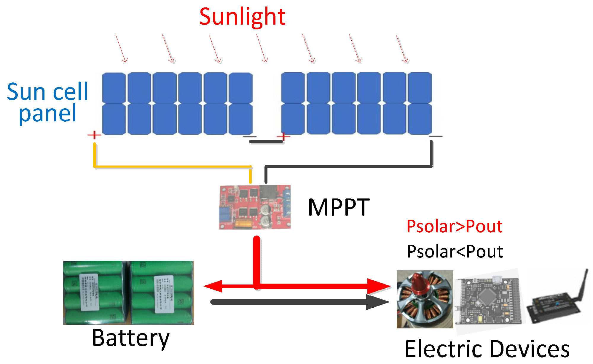
Figure 1 shows the composition of the energy system. The solar cells are connected in a fixed structure, covering the given surface of the wing or other parts of the aircraft such as the tail or fuselage. During the day, solar cells convert light energy into electricity. The maximum power point tracking (MPPT) ensures that the solar cell operates at the maximum power point [17]. The generated energy is first used to power the motor and on-board electronics, and then the remaining energy is used to charge the battery. At night, solar panels cannot provide energy. The energy consumed by each component is provided by the battery. The next day, the solar cells work again to provide energy to the system, and a new cycle begins.
Solar arrays are a key component in UAV energy systems. At the maximum power point, the available solar power is the largest; the power output equals the multiplication of the voltage by the current under the maximum power point. Solar cells should work exactly at this point when the ratio between Pmax and light intensity exactly represents the efficiency of solar cells [18]. The current of a solar cell is proportional to its area, and it is almost linear with the change in light intensity [19]. Temperature also affects the characteristics of solar cells. In general, considering the same irradiation conditions, solar cells can provide higher power at low temperatures [20].
One of the pieces of equipment in the energy system is maximum power point tracking (MPPT), which is an upgraded new product of traditional solar charge and discharge control. By adjusting the working status (voltage, current) of the solar panel, the solar panel is always operated at the maximum power point of the V-A characteristic curve, and more solar power is output to obtain greater efficiency [21]. The common MPPT technique can be classified into four categories: classical, intelligent, optimal, and hybrid depending on the tracking algorithm [22]. A considerable amount of research has been devoted to the development of more efficient and easier-to-use MPPT technology such as the Particle Swarm optimization (PSO) algorithm [23] or the incremental conductance method [24].
Energy storage equipment is extremely important for solar aircraft that achieve long-endurance or permanent flight. The energy in the energy storage device is used to supply the aircraft in the case of low solar power or sustained flight at night. Therefore, there are several important features of the equipment, such as stable charge-and-discharge performance and greater energy density to minimize battery quality.
3. Energy System Management Method
3.1. Solar Radiation Power of UAV
Solar radiation depends on many variables such as geographical location, date and time, flight position, weather conditions, and ground and air reflectance. In the energy balance calculation, due to the characteristics of the solar vehicle, the calculation process is simplified accordingly. Then, according to the simplified model, the solar radiation is calculated, and parameters such as solar power can be obtained.
The output of the solar power is mainly determined by solar cell efficiency, MPPT efficiency, solar cell array area, beam radiation intensity, and beam incident angle. The efficiency of single-crystal silicon cells used in industry is more than 20%. Other high-efficiency materials are not practical enough in industry due to production costs and production processes [25]. MPPT efficiency is a definite parameter whose main function is to obtain the maximum output power of a solar cell [26]. The intensity of the beam and the angle of incidence of the beam depend on the time of day and the date of the day, and have an important effect on the output power. The impact of the above factors on the solar output power will be specifically analyzed.
Beam radiation GH is a parameter that changes with time and environmental conditions; according to the literature [27], one can obtain the expression:
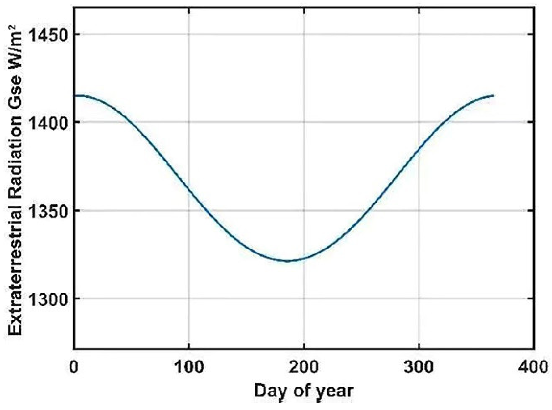
First, the parameter Gse is the extraterrestrial radiation intensity, and its expression is shown in Equation (2):
where Gsc = 1367 W/m2 is the radiation constant.
Above them, (°), n is the n-th day of the year, . Therefore, the time-varying extraterrestrial radiation is shown in Figure 2.
Second, the parameter τb indicates atmospheric turbidity. This paper uses the “transparent” atmosphere as an example. Its expression is [28]:
Atmospheric mass: , related to the angle of incidence of the solar beam. Flight height A = 0.2 km and flight environmental conditions are shown in Table 1.
Therefore, the formula for calculating the coefficient of “transparent” atmospheric turbidity:
The angle of incident of the solar beam is a parameter that varies with latitude, time, and date. The solution of its expression is described in detail in [27]. Here is a simple expression:
where δ is the declination angle of the sun, ω is the hour of sun, Φ is the latitude, and β is the slope angle. In this paper, the aircraft model is assumed to be reduced to a certain height of the horizontal plate, and the impact caused by the change of the flying attitude angle is small, and the impact on the incident angle of the solar array as a whole is small. Therefore, the angle and angle of incidence are:
According to the expression, the influencing factors can be analyzed. This paper selects a latitude of 40° (N); the angle δ is obtained as follows (using an exact approximation equation) [28]:
As a result, there are many factors that affect the incident angle of the solar beam. Now, we can solve the fixed latitude and fixed beam incident angle. After the above analysis and discussion, the corresponding radiation turbidity τb and beam radiant intensity GH at the desired date and time can be calculated.
One must obtain the input solar power Psolar calculation expression and determine the influence parameters one by one, which can describe in detail the power that the solar cell can generate and the energy that can be obtained in a day. Solar power expressions from the literature are as follows [29]:
Here, solar cell efficiency ηsm, MPPT efficiency ηmppt, array area Ssm (m2), and beam radiation intensity GH (W/m2). The solar array power can be calculated based on the solar beam radiation intensity and beam incident angle calculated in the previous section.
3.2. UAV Energy Output
The analysis in regard to the energy input and output balance of solar aircraft is the key to flying UAVs during long flights. One must analyze the solar power because the plane needs to use power, and the change trend of battery storage energy must be obtained to determine the flight status of UAV. For low-altitude long-season solar-powered aircraft, the basic method to maintain long-time flight is to maintain a low-altitude level flight for maximum energy efficiency, and at the same time use solar cells to obtain energy from sunlight to charge the storage battery in the case of insufficient light intensity or continuous flight at night.
For energy input/output balance performance analysis, it is assumed that the aircraft sets minimum altitude to maintain the minimum power required for level flight and maintain horizontal flight. Total required power can be calculated as follows:
where ηprop is the efficiency of the electric propulsion power, Pav and Ppld represent the required avionics and the payload power, and Plevel is the power required of the level flight as below [30]:
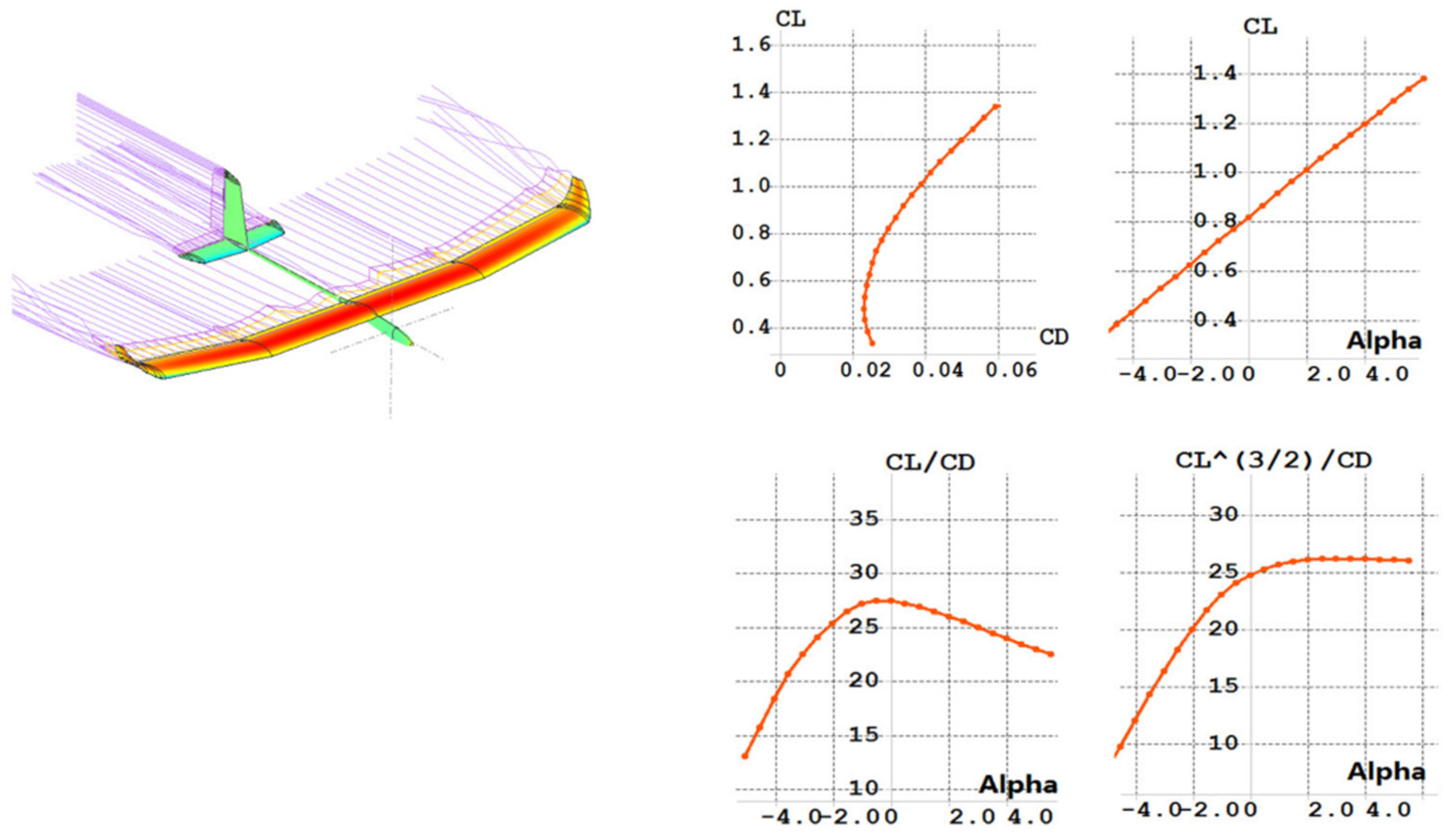
where T is the thrust, D is the drag, L is the lift, V is the velocity, S is the wing area, mtot the total mass, g the earth gravity, ρ the air density, and Cd and Cl the drag and lift coefficient, respectively.
The aerodynamic parameters of the aircraft model are shown in Table 2. Among them, Cl and Cd are lift coefficient and drag coefficient, respectively. The above aerodynamic coefficients can be obtained through the simulation software Xfoil [31]. For example, the simulation results of the aircraft model calculated in this paper are shown in Figure 3. The detailed design parameters are shown in the Section 5.
The battery power is an important parameter for the balance of energy input and output of the aircraft. During the daytime, solar power is provided to power the propulsion assembly and the onboard equipment. When the solar array power is greater than the output power, the solar array begins to charge the storage battery until the sunset solar power is less than the output power. When the solar power is less than the output power or in the night, the required energy output of the aircraft is entirely derived from the battery. Therefore, the state of charge of the storage battery can be used as the parameters to evaluate the energy balance of the system. Battery energy Ebatt is expressed as:
One must define the state of charge (SOC) of the battery, the ratio of the current battery capacity to the rated capacity of the battery [32], and its expression [33]:
Here, Ebattery is the battery rated capacity. According to the design of the battery self-protection circuit, the SOC of the battery is required to be maintained within a certain safety range, which is 0.2 ≤ SOC ≤ 1, the SOC minimum limit threshold SOClim ≥ 0.15 [30]. When the battery is overly discharged, the SOC state is too low to cause irreversible damage to the battery, causing the battery’s usable capacity to rapidly attenuate. Thus, considering the long battery life design, one must keep the SOC value above the minimum threshold.
3.3. Criteria of Method Extended
For the aircraft to be able to fly permanently and have better multi-day flight stability, it is necessary to expand the energy balance design method. In general, a necessary and sufficient condition for an aircraft to perform long-distance flight over the day and night is its surplus time texc > 0. The surplus excess time is defined as [34]:
Here, t = teq is the time when the solar power is equal to the output power at the next morning; tst is the sunrise time. The significance of surplus excess time is as follows: when t = teq due to the influence of clouds and other factors Psolar = 0, how long can the remaining battery capacity be used to maintain the flight. One of the design methods given in [7,35] is to maximize surplus time, i.e., max (texc). However, due to cloud cover and other factors, the design method cannot give an intuitive long-time flight stability analysis for the battery charging process. This paper will provide an intuitive and detailed design method of surplus time as an extension criterion of the long-time aircraft energy system management design method.
For the demand of aircraft across the day and night, the impact of local environmental conditions on the aircraft should be considered, and a surplus excess time texc that meets the stability of long-term flight stability should be designed. The specific expansion criteria are as follows:
- Determine the local geographical latitude , the date Date of the aircraft flight, and the date window Date [min, max] for continuous flight.
- Calculate the length of the night , according to the date window Date [min, max] of the flight.
- Earnings time calculation:
- Change in night time caused by date change:
- Estimate the influence of meteorological factors such as clouds and water fog in the early morning and evening . The impact of rainfall is fatal for solar-powered aircraft; thus, the selection date of flight should, as far as possible, avoid local rainy days.
- The addition time because of the night flight environment effects on the aircraft, such as gusts, vertical turbulence, etc., causes additional power consumption of the aircraft.
Thus, the total demand surplus time:
The endurance of the UAV is influenced by many factors such as battery size, altitude velocity and time of flight, aerodynamic parameters, and propulsion system of the aircraft, and thus an appropriate battery capacity achieves longer endurance [36]. Thus, the installed battery capacity is a crucial parameter for the aircraft, which affects the ability of the aircraft to store and release electrical energy. The battery capacity is too small, and the stored energy is insufficient to support the aircraft flying at night at long endurance; the battery capacity is too large to be fully charged during the day, and the excess battery quality is a burden on the aircraft, which additionally increases power consumption. Therefore, the battery capacity required for flight needs to be calculated. The method for determining the battery capacity is as follows:
- (1)
- The battery capacity required for the surplus period:
- (2)
- Maximum battery capacity required for night flight:
- (3)
- Battery design minimum state value SOCmin.
- (4)
- The required minimum battery capacity:
The above process optimizes design of the surplus time at the required flight date window Date [min, max] to meet the mission requirements of the solar UAV continuous flight on the selection date. The following section will verify the validation of the method.
4. UAV Platform Parameter Design Method
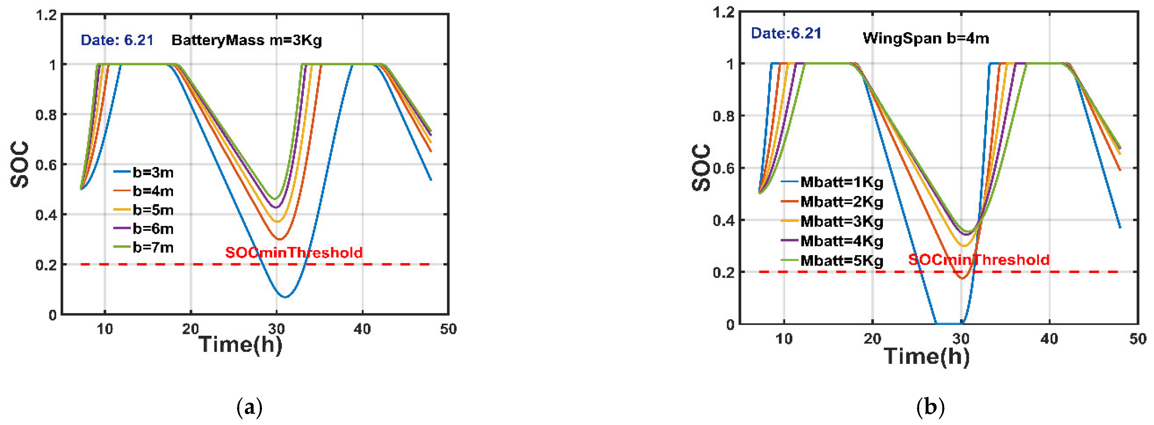
The third part gives a detailed description of the energy system management method of solar aircraft. However, according to the expressions in Equations (8), (9) and (11), it can be understood that the design parameters of the aircraft are different, which will greatly affect its long-term or permanent flight performance. As shown in Figure 4, the wingspan of an aircraft influences the solar power obtained, and the quality of the carried battery determines the energy that can be stored.
According to Figure 4a, when the battery mass is fixed, the wing span of the aircraft changes, and the charging time of the aircraft battery, the battery full time, the flight duration, and the SOC status value will change. The specific performance is as follows: when the wing span of the aircraft increases, the battery charging speed gradually increases, and the time for full battery charging increases. At this point, the aircraft will have the remaining power for the aircraft to climb, it will convert the energy into potential energy storage, and when the solar power is low, it can be used for low-power gliding of the aircraft, increasing the flight time of the aircraft. At lower solar power or at night, the larger wingspan allows the aircraft to fly at lower power, so it takes longer to continue flying and the minimum SOC of the battery state of charge increases accordingly. Figure 4b shows the effect of the battery mass carried by the aircraft on the permanent flight performance of the aircraft when the aircraft wingspan is fixed. The quality of the battery carried is too small; although the charging speed is faster, the stored energy is less, and it is impossible to maintain the continuous flight of the aircraft across the day and night. Therefore, it is necessary to increase the quality of the carried battery. However, as the battery quality increases, the speed of charging will also be reduced. To avoid overloading the battery, this will lead to the battery not being fully charged, and the remaining uncharged battery will become an additional burden on the aircraft and increase the power consumption of the aircraft. Therefore, the optimization of the wingspan and battery quality of the aircraft must be carefully optimized.
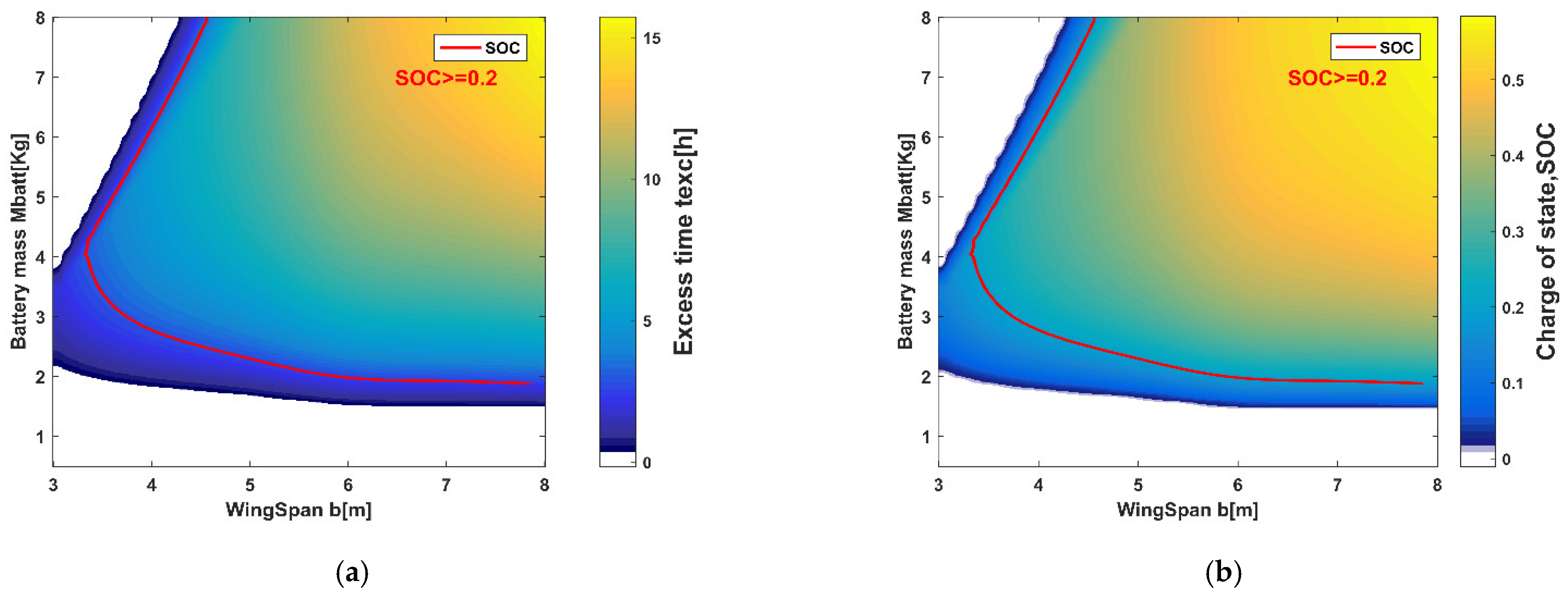
The energy system management method of the third section is used to analyze the effects of wingspan and battery quality on the surplus time and battery state of charge (Date, 22 June), as shown in Figure 5. The aircraft wingspan and battery quality optimization design domain are determined based on the SOC threshold.
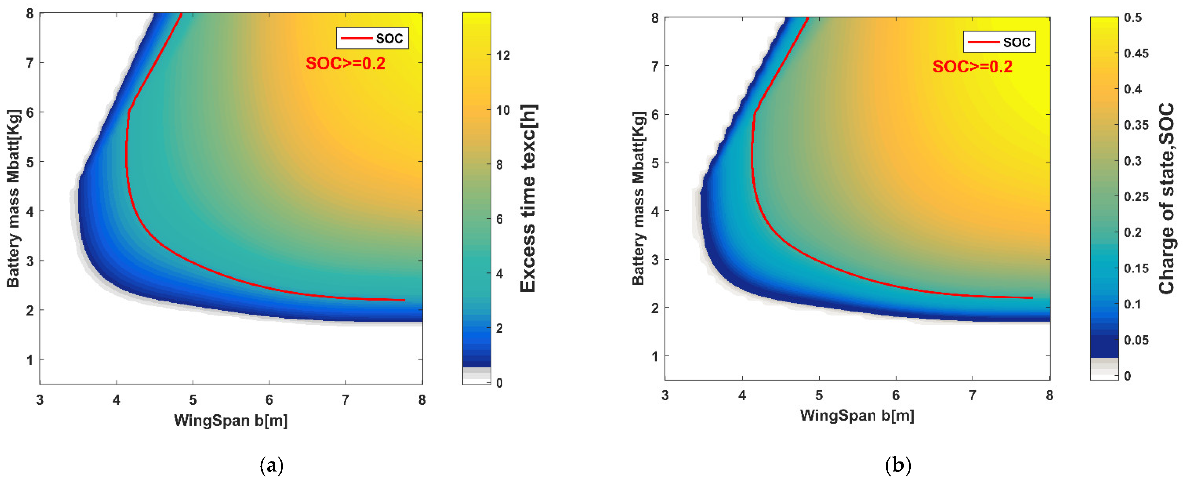
Figure 5 shows the optimal relationship between wing span and mass versus aircraft surplus time and SOC. However, according to the expressions in Equations (5)–(8), the solar power follows the date, so there should be some difference in the results of the optimization on different dates. For example, the date window designed in this article is the month, as shown in Figure 6. It is the optimization result of Date, 21 April. Compared to Date, there is a significant difference on 22 June. Therefore, to achieve permanent flight of the aircraft, the parameters of the aircraft need to be designed and selected using the boundary optimization results of the flight date of the aircraft. Later in the simulation test, according to the boundary date optimization results, one must select the aircraft design parameters for permanent flight performance verification.
5. The Method Simulation Results
According to the expansion criteria, the nominal latitude determined in this paper is 40° (N), and the test flight date is 21 June. The aircraft’s life time window is required to be relative to the flight date, that is, 21 April to 21 August. The battery used in this article is a high energy density lithium-ion battery, model SONY18650VTC6, 6S configuration (21 V), energy density kbatt = 243 Wh/kg [37].
Then, according to the literature [27], one must calculate the night time of the date window, Date, 22 June, the minimum night time , Date, 21 April, and the maximum night time . Thus, . The influence of factors such as cumulus clouds in the early morning and evening on the charging process of the aircraft is selected , among which is the cloud layer or fog thickness factor [38]. For nighttime flight, the ambient air flow disturbances and the additional power loss caused by the model correction are chosen . Therefore, the minimum surplus time is required to ensure that the aircraft flies during a long flight in the date window. According to expression Equation (18), the aircraft carries the battery quality .
This article uses SunPower E60 solar cells, with efficiency up to 23.7%, taking into account the actual test deviation, calculation, and simulation testing using 22% [26]. The simulation test will analyze the aircraft model’s solar power input and nominal demand power output curve characteristics, as well as verify the performance of the model’s continuous permanent flight on different days within the design date window.
5.1. UAV Input/Output Power
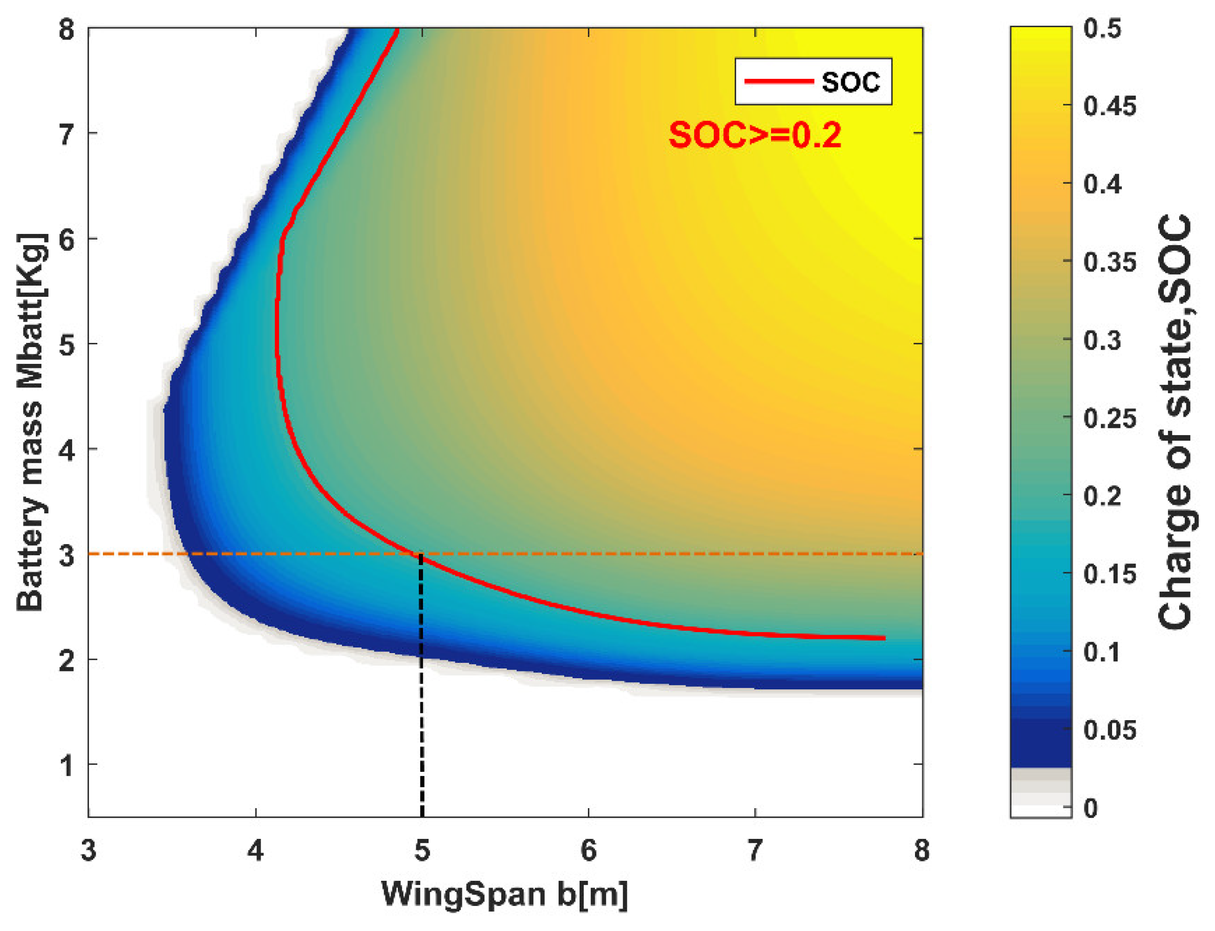
One must validate the performance of the energy system design method stated in the second part of the method. Keeping the model flying at a fixed altitude during the simulation can obtain the required power for the aircraft’s level flight, from which the nominal output power of the aircraft can be calculated. The nominal output power can be used to calculate the battery capacity required for a day-night flight on the corresponding date. Combined with the surplus time of the date, the capacity of the battery needed for the date window to maintain a stable and continuous flight can be obtained. Simulation test aircraft model parameters are shown in Table 3. The optimum design point of the aircraft is shown in Figure 7.
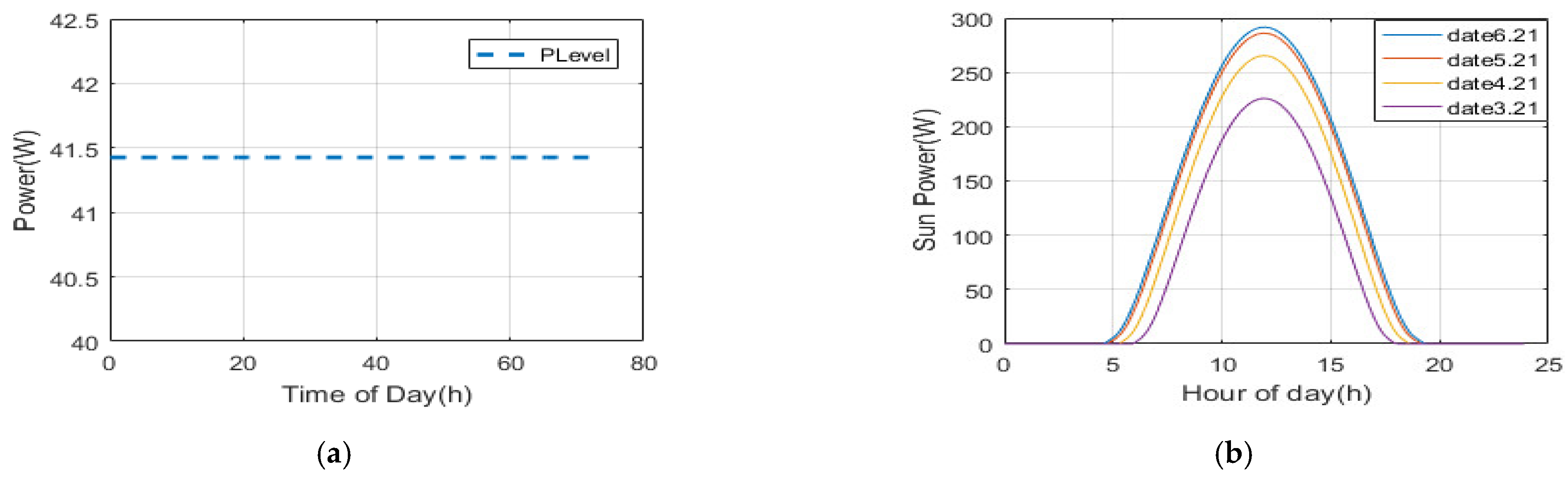
Shown in Figure 8a is the aircraft’s leveling power at H = 200 m. The nominal output power is illustrated. The design requires a power of 35 W–50 W. The main factor is to consider the effect of gusts and vertical air currents on the model, and to correct the model. Figure 8b is the solar power curve of the aircraft on the date of 22 June. In the Figure 8, the maximum solar power changes over time.
5.2. Power Balance Simulation Test of System
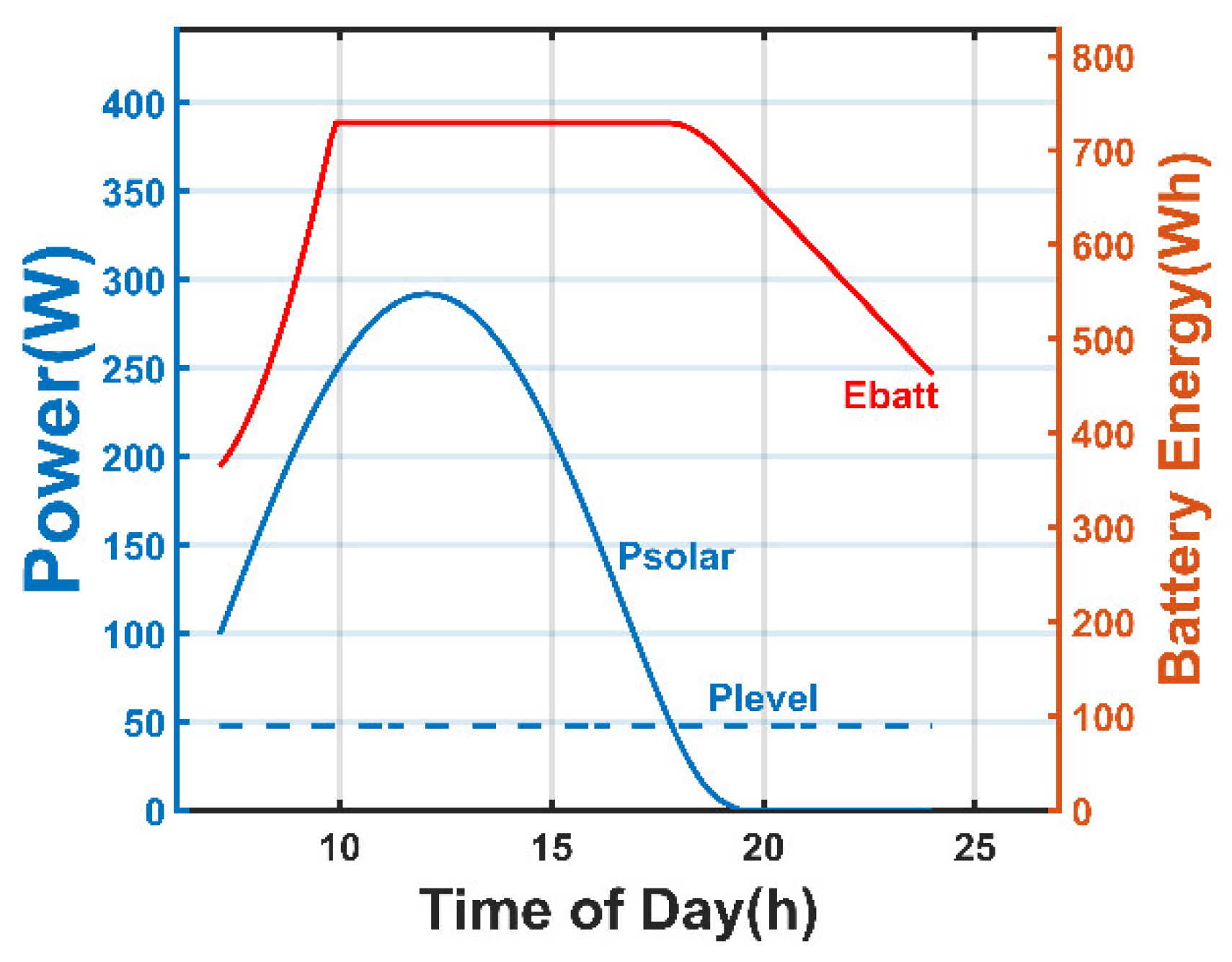
The first step for a solar-powered aircraft to achieve a multi-day flight is to complete a single day-night flight. Therefore, one must first describe the state of the aircraft on the first day of launch. As shown in Figure 9, it is the energy power curve of Date 22 June. The solar-powered aircraft took off at 7 o’clock and the battery power status was 0.5. At this time Psolar > Plevel, when maintaining the aircraft’s level flight; while charging the battery, the SOC curve can be observed. After less than 3 h, the battery was full. The aircraft can climb the height to convert energy into potential energy storage.
After 6:00 p.m., battery power began to be consumed to keep the aircraft flying in the evening. After sunrise the next day, the second cycle began.
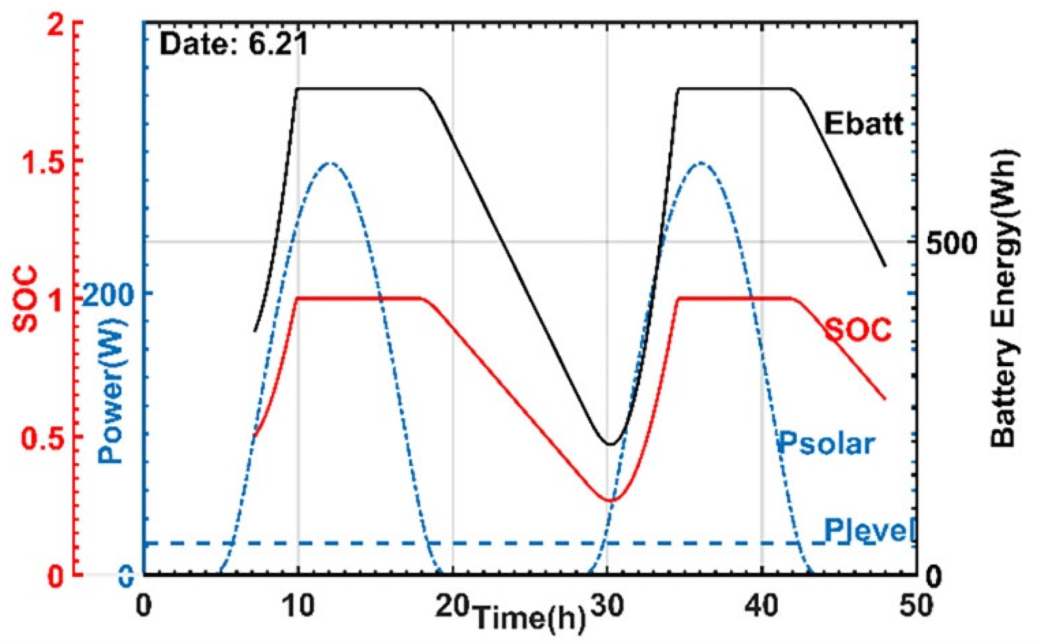
Second, the aircraft continued to fly for several days. Figure 10 shows the flight simulation of the aircraft for three days, using the SOC status level to evaluate the ability of the aircraft to continue flying during the day and night. The SOC shown in the Figure 10 is at a minimum value of 0.3. That is, when the solar input power is equal to the output power on the second day, about 30% of the battery remains. The solar power is then greater than the output power, which can gradually charge the storage battery. The surplus time of the remaining battery power and the full battery time of the battery meet the basic requirements for day and night flight. The simulation result is superior to the performance of SkySailor [6] and SoLong [7].
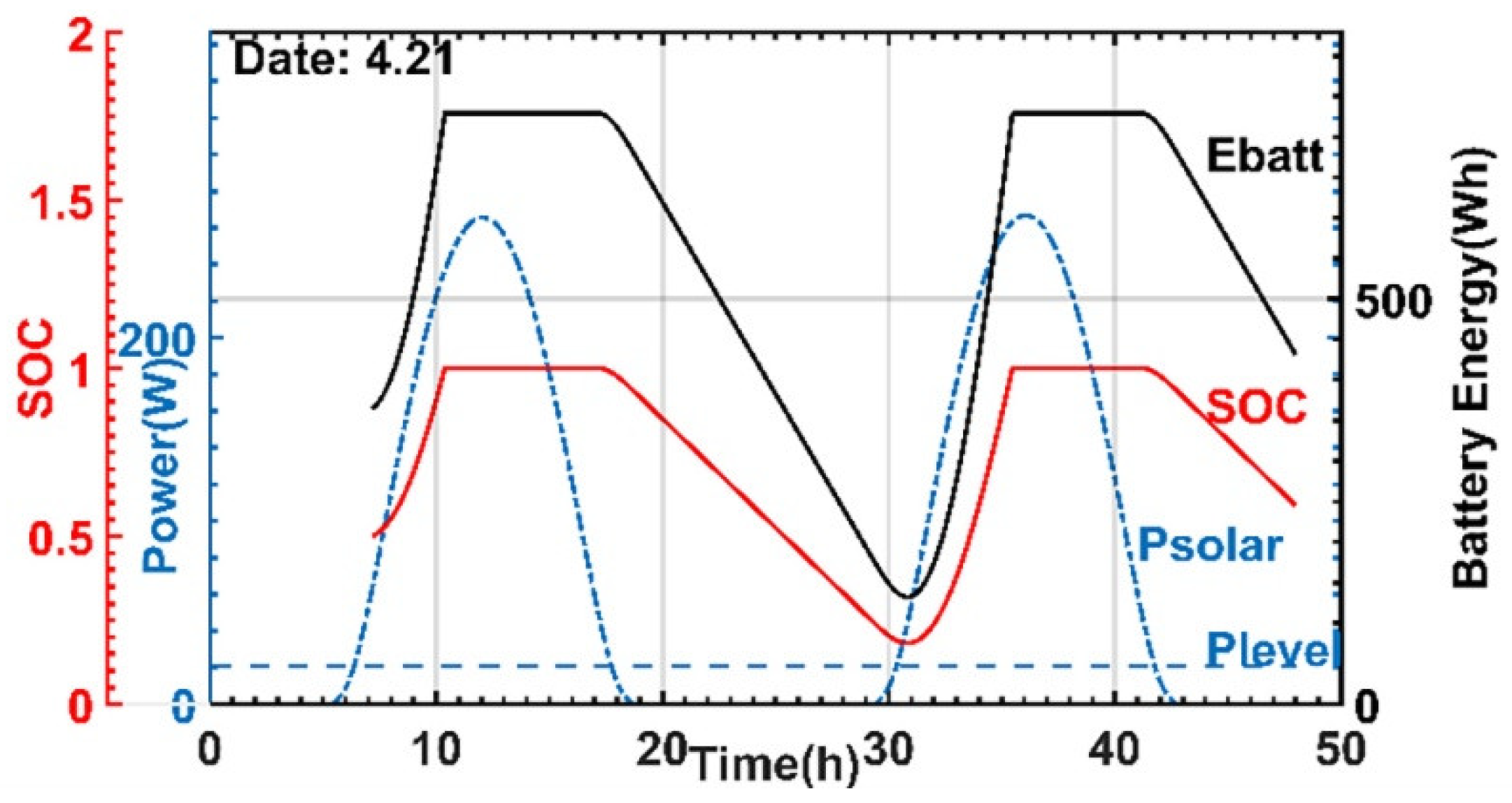
Third, the energy input and output energy performance curves for different days are analyzed, as shown in Figure 11, which is the energy curve for the Date 21 April. The flight environment conditions are the same as the Date 22 June. Due to the influence of the date change on the radiation intensity of the light beam, the solar output power is significantly reduced, so that the time for charging the battery becomes longer and reduces the time for obtaining the full battery. Meanwhile, days become shorter and nights increase as the date changes, the discharge time of the battery is also greatly increased, and the residual value of the battery’s power decreases, as well as the surplus time. The lowest value of the state of charge parameter SOC is 0.21, which also decreases synchronously and approaches the SOC design threshold. Therefore, the date change has a significant influence on the parameters of the solar aircraft.
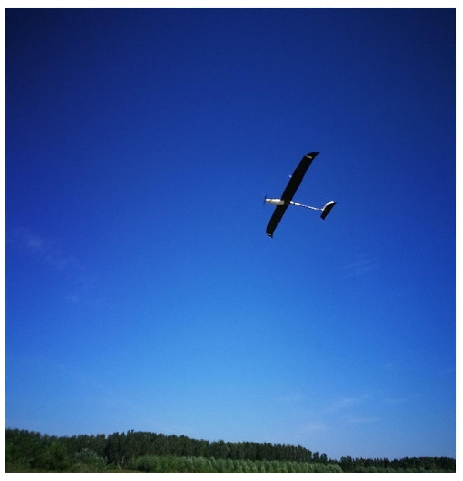
Finally, a flight experiment was completed at noon on 9 August. The location of the flight was in Tianjin (40° N, 117° E), and the solar irradiance and the temperature of the flight experiment were about 621 W/m2 and 33 °C. Both Figure 12 and Figure 13 demonstrate the altitude and throttle data of the UAV during flight. The increase in altitude requires more thrust, but the throttle decrease could lead to a lower altitude for UAV in general. However, Figure 12 shows that the throttle decreases from 37% to 27%, while the altitude changes from 64 m to 78 m for the UAV at the time of 18 min. The reason was the UAV perceived thermal energy distributed on the earth and gathered energy from the thermal energy, soaring to a higher altitude. This method allows a UAV to save energy since the UAV gains benefit from thermal energy with lower throttle.
6. Conclusions
This paper describes a design of energy system management methods for low-altitude and long-time solar-powered aircraft, and the criteria for the expansion of the method, which increases the stability and robustness of the aircraft’s multi-day flight performance. The energy input/output balance of the UAV is analyzed by the power of solar panel and cruise thrust. The surplus time and battery capacity are estimated by the expansion method.
In the part of the paper pertaining to UAV platform design, the influence of the parameters of the solar-powered vehicle on the continuous flight performance is discussed, and the optimal parameters of wingspan and battery mass are selected by cruise power and surplus time for simulation. Restricted by the sunlight, June is selected as an appropriate month for simulation to accomplish the task of multi-day flights.
In the simulation, the aircraft was taking off from 7 a.m. on the first day to verify the aircraft’s complete inter-day and night-flying capability, and achieved the long-time flight of aircraft on 22 June to fulfil the mission requirements for multi-day flights. The minimum SOC of battery during the flight meets the basic requirements for continuing flying. In addition, the simulation also analyzes and verifies the ability of the aircraft to undergo continuous flight on 21 April, the edge of the time window selected in this paper. The result suggests that the battery energy and SOC during flight decreased compared to June due to the lower light radiation time in a different month. The feasibility of the proposed method and process is verified in this paper and the performance of the designed UAV (wingspan 5 m, 72 h endurance) is better than the SkySailor (wingspan 3.2 m, 24 h endurance) and SoLong (wingspan 4.75 m, 48 h endurance).
Further research will focus on the development of actual flight equipment to verify the validity of the practical application of this theoretical method and apply the solar-powered flight platform. The prototype solar UAV will complete flight experiments from June to August each year restricted by the sunlight. In addition, the proposed method and model in this article will be modified by the data collected in the flight.
Author Contributions
Conceptualization and methodology, K.L. and A.B.; software, Y.W. and A.B.; validation, Y.W. and S.W.; writing—review and editing, Y.W. and Y.L.; supervision, K.L.; project administration, D.W.; funding acquisition, K.L. All authors have read and agreed to the published version of the manuscript.
Funding
This work is supported by the National Natural Science Foundation of China (No. 61773039) and (No. 20XXJCJQXX1045).
Institutional Review Board Statement
Not applicable.
Informed Consent Statement
Not applicable.
Data Availability Statement
Not applicable.
Conflicts of Interest
The authors declare no conflict of interest.
References
- Hening, S.; Baumgartner, J.; Teodorescu, M.; Nguyen, N.T.; Ippolito, C.A. Distributed sampling using small unmanned aerial vehicles (UAVs) for scientific missions. In Proceedings of the AIAA InfoTech and Aerospace Conference, Boston, MA, USA, 19–22 August 2013. [Google Scholar]
- Malaver, A.; Motta, N.; Corke, P.; Gonzalez, F. Development and Integration of a Solar Powered Unmanned Aerial Vehicle and a Wireless Sensor Network to Monitor Greenhouse Gases. Sensors 2015, 15, 4072–4096. [Google Scholar] [CrossRef] [PubMed]
- Jiang, R.; Wang, P.; Xu, Y.; Zhou, Z.Y.; Luo, X.W.; Lan, Y.B.; Zhao, G.P.; Sanchez-Azofeifa, A.; Laakso, K. Assessing the Operation Parameters of a Low-altitude UAV for the Collection of NDVI Values Over a Paddy Rice Field. Remote Sens. 2020, 12, 1850. [Google Scholar] [CrossRef]
- Wu, J.F.; Wang, H.L.; Li, N.; Yao, P.; Huang, Y.; Su, Z.K.; Yu, Y. Distributed trajectory optimization for multiple solar-powered UAVs target tracking in urban environment by Adaptive Grasshopper Optimization Algorithm. Aerosp. Sci. Technol. 2017, 70, 497–510. [Google Scholar] [CrossRef]
- Ackerman, E. Giant Solar-Powered UAVs are Atmospheric Satellites. IEEE Spectrum 2013. Available online: https://0-spectrum-ieee-org.brum.beds.ac.uk/giant-solar-powered-uavs-are-atmospheric-satellites (accessed on 21 August 2013).
- Noth, A. Design of Solar Powered Airplanes for Continuous Flight. Ph.D. Thesis, ETH, Zurich, Switzerland, 2008. [Google Scholar]
- Cocconi, A. AC Propulsion’s Solar Electric Powered SoLong UAV; AC Propulsion: San Dimas, CA, USA, 2005; Available online: https://xpda.com/junkmail/junk173/ACP_SoLong_Solar_UAV_2005-06-05.pdf (accessed on 5 June 2005).
- Laurenzo, R. Soaring on a Solar Impulse. Aerosp. Am. 2009, 5, 32–36. [Google Scholar]
- Cheng, K.; Wang, Z.; Zhou, Z. Exploring Effects of Solar-Powered Airplane Operating Conditions on Solar Cell Performance. J. Northwest. Polytech. Univ. 2012, 4, 535–540. [Google Scholar]
- Lee, J.S.; Yu, K.H. Optimal Path Planning of Solar-Powered UAV Using Gravitational Potential Energy. IEEE Trans. Aerosp. Electron. Syst. 2017, 52, 1442–1451. [Google Scholar] [CrossRef]
- Al-rabghi, O.M.; Akyurt, M.M. A survey of energy efficient strategies for effective air conditioning. Energy Convers. Manag. 2004, 45, 1643–1654. [Google Scholar] [CrossRef]
- Ipsakis, D.; Voutetakis, S.; Seferlis, P.; Stergiopoulos, F.; Elmasides, C. Power management strategies for a stand-alone power system using renewable energy sources and hydrogen storage. Int. J. Hydrogen Energy 2009, 34, 7081–7095. [Google Scholar] [CrossRef]
- Abbe, G.; Smith, H. Technological development trends in Solar-powered Aircraft Systems. Renew. Sustain. Energy Rev. 2016, 60, 770–783. [Google Scholar] [CrossRef]
- Zhang, C.Y.; Zhang, C.M.; Li, L.Y.; Guo, Q.B. Parameter analysis of power system for solar-powered unmanned aerial vehicle. Appl. Energy 2021, 295, 117031. [Google Scholar] [CrossRef]
- Panagiotou, P.; Tsavlidis, I.; Yakinthos, K. Conceptual design of a hybrid solar MALE UAV. Aerosp. Sci. Technol. 2016, 53, 207–219. [Google Scholar] [CrossRef]
- Dwivedi, V.S.; Kumar, P.; Ghosh, A.K.; Kamath, G.M. Selection of size of battery for solar powered aircraft. In Proceedings of the 11th IFAC Conference on Control Applications in Marine Systems, Robotics, and Vehicles, Opatija, Croatia, 10–12 September 2018. [Google Scholar]
- Soon, T.K.; Mekhilef, S.; Safari, A. Simple and low cost incremental conductance maximum power point tracking using buck-boost converter. J. Renew. Sustain. Energy 2013, 5, 1777–1790. [Google Scholar]
- Miles, R.W.; Hynes, K.M.; Forbes, I. Photovoltaic Solar Cells: An Overview of State-of-the-Art Cell Development and Environmental Issues. Prog. Cryst. Growth Charact. Mater. 2005, 51, 1–42. [Google Scholar] [CrossRef]
- McEvoy, A.; Markvart, T.; Castaner, L. Practical Handbook of Photovoltaics: Fundamentals and Applications, 2nd ed.; Academic Press: Cambridge, MA, USA, 2012; ISBN 978-0-12-385934-1. [Google Scholar]
- Markvart, T. Solar Electricity; John Wiley: New York, NY, USA, 1994; ISBN 9780471941613. [Google Scholar]
- Xiao, W.; Elnosh, A.; Khadkikar, V.; Zeineldin, H. Overview of maximum power point tracking technologies for photovoltaic power systems. In Proceedings of the 37th Annual Conference of the IEEE Industrial Electronics Society, Melbourne, Australia, 7–10 November 2011. [Google Scholar]
- Bollipo, R.B.; Mikkili, S.; Bonthagorla, P.K. Hybrid, Optimal, Intelligent and Classical PV MPPT Techniques: A Review. CSEE J. Power Energy 2021, 7, 9–33. [Google Scholar]
- Ishaque, K.; Salam, Z.; Amjad, M.; Mekhilef, S. An improved particle swarm optimization (PSO) based MPPT for PV with reduced steady state oscillation. IEEE Trans. Power Electron. 2012, 27, 3627–3638. [Google Scholar] [CrossRef]
- Safari, A.; Mekhilef, S. Implementation of incremental conductance method with direct control. In Proceedings of the 2011 IEEE Region 10 Conference, Bali, Indonesia, 21–24 November 2011. [Google Scholar]
- Green, M.A.; Blakers, A.W.; Shi, J.; Keller, E.M.; Wenham, S.R. 22.6% efficient silicon solar cells. In Proceedings of the 4th International Photovoltaic Science and Engineering Conference, Sydney, Australia, 14–17 February 1989. [Google Scholar]
- De Brito, M.; Sampaio, L.; Luigi, G.; Melo, G.; Canesin, C. Comparative analysis of MPPT techniques for PV applications. In Proceedings of the 2011 International Conference on Clean Electrical Power, Ischia, Italy, 14–16 June 2011. [Google Scholar]
- Duffie, J.A.; Beckman, W.A. Solar Engineering of Thermal Processes, 3rd ed.; John Wiley: Hoboken, NJ, USA, 2006; ISBN 978-0-471-69867-8. [Google Scholar]
- Duffie, J.A.; Beckman, W.A. Solar Engineering of Thermal Processes, 4th ed.; John Wiley: Hoboken, NJ, USA, 2013; ISBN 978-0-470-87366-3. [Google Scholar]
- Klesh, A.T.; Kabamba, P.T. Solar-Powered Aircraft: Energy-Optimal Path Planning and Perpetual Endurance. J. Guid. Control Dyn. 2009, 32, 1320–1329. [Google Scholar] [CrossRef] [Green Version]
- Hosseini, S.; Dai, R.; Mesbahi, M. Optimal path planning and power allocation for a long endurance solar-powered UAV. In Proceedings of the 2013 American Control Conference, Washington, DC, USA, 17–19 June 2013. [Google Scholar]
- Mark, D. XFOIL 6.9 User Primer; MIT Aero & Astro: Cleveland, OH, USA, 2001; Available online: http://web.mit.edu/aeroutil_v1.0/xfoil_doc.txt (accessed on 30 November 2001).
- Moura, S.J.; Callaway, D.S.; Fathy, H.K.; Stein, J.L. Tradeoffs between battery energy capacity and stochastic optimal power management in plug-in hybrid electric vehicles. J. Power Source 2010, 195, 2979–2988. [Google Scholar] [CrossRef]
- Wirth, L.; Oettershagen, P.; Ambuhl, J.; Siegwart, R. Meteorological path planning using dynamic programming for a solar-powered UAV. In Proceedings of the 2015 IEEE Aerospace Conference, Big Sky, MT, USA, 7–14 March 2015. [Google Scholar]
- Oettershagen, P.; Melzer, A.; Mantel, T.; Rudin, K.; Lotz, R.; Siebenmann, D.; Leutenegger, S.; Alexis, K.; Siegwart, R. A solar-powered hand-launchable UAV for low-altitude multi-day continuous flight. In Proceedings of the 2015 IEEE International Conference on Robotics and Automation, Seattle, WA, USA, 26–30 May 2015. [Google Scholar]
- Leutenegger, S.; Jabas, M.; Siegwart, R.Y. Solar airplane conceptual design and performance estimation. J. Intell. Robot. Syst. 2010, 61, 545–561. [Google Scholar] [CrossRef]
- Rajendran, P.; Smith, H. Development of Design Methodology for a Small Solar-Powered Unmanned Aerial Vehicle. Int. J. Aerospace Eng. 2018, 2018, 1–10. [Google Scholar] [CrossRef] [Green Version]
- Overview of Lithium Ion Batteries. Available online: https://www.epectec.com/downloads/Panasonic-Lithium-Ion-Battery-Overview.pdf (accessed on 1 January 2007).
- Kimura, K.; Stephenson, D. Solar radiation on cloudy days. ASHRAE J. 1969, 75. [Google Scholar]
Figure 1.
Solar UAV energy system composition.

Figure 2.
Curve of extraterrestrial radiation intensity as a function of time.

Figure 3.
Aircraft flow field and aerodynamic parameters.

Figure 4.
Effect of aircraft wingspan (a) and battery mass (b) changes vs. SOC (Date 22 June).

Figure 5.
Surplus excess time texc (a) and charge of state (b) vs. wing span and battery mass (Date, 22 June).
Figure 5.
Surplus excess time texc (a) and charge of state (b) vs. wing span and battery mass (Date, 22 June).

Figure 6.
Relationship between surplus time texc (a) and charge of state (b) vs. wing span b and battery mass Mbatt with time change (Date, 21 April).
Figure 6.
Relationship between surplus time texc (a) and charge of state (b) vs. wing span b and battery mass Mbatt with time change (Date, 21 April).

Figure 7.
Aircraft optimization design point (Date, 21 April).

Figure 8.
Level flying power (a) and solar power (b) curves.

Figure 9.
Energy power curve of 22 June (flight simulation).

Figure 10.
Energy power curve of Date 22 June simulated continuous flight.

Figure 11.
Energy power curve of 21 April simulated continuous flight.

Figure 12.
Altitude and throttle of UAV flight on 9 August (flight experiment).

Figure 13.
Flight experiment of prototype solar UAV on 9 August.


Table 1.
Flight environmental parameters.
| Parameter | Latitude | Altitude | Visibility | Weather | Wind | Precipitation |
|---|---|---|---|---|---|---|
| Value | 40° (N) | 200 m | 23 Km “transparent” sky | Sunny (almost no clouds) | Level 3 below | No |
Table 2.
Aircraft aerodynamic parameters.
| Parameter | ηprop | Pav | Ppld | Cl | Cd | A |
|---|---|---|---|---|---|---|
| Value | 0.7 | 10 W | 0 W | 0.883 | 0.041 | 200 m |
Table 3.
Aircraft model parameters.
| Parameter | Value |
|---|---|
| Wingspan | 5 m |
| Aspect ratio | 13.3 |
| Wing area | 1.875 m2 |
| Total mass | 6.8 kg |
| Battery mass | 3 kg |
| Level velocity | 8 m/s |
| Solar cell area | 1.688 m2 |
Publisher’s Note: MDPI stays neutral with regard to jurisdictional claims in published maps and institutional affiliations. |
© 2022 by the authors. Licensee MDPI, Basel, Switzerland. This article is an open access article distributed under the terms and conditions of the Creative Commons Attribution (CC BY) license (https://creativecommons.org/licenses/by/4.0/).
Share and Cite
MDPI and ACS Style
Li, K.; Wu, Y.; Bakar, A.; Wang, S.; Li, Y.; Wen, D. Energy System Optimization and Simulation for Low-Altitude Solar-Powered Unmanned Aerial Vehicles. Aerospace 2022, 9, 331. https://0-doi-org.brum.beds.ac.uk/10.3390/aerospace9060331
AMA Style
Li K, Wu Y, Bakar A, Wang S, Li Y, Wen D. Energy System Optimization and Simulation for Low-Altitude Solar-Powered Unmanned Aerial Vehicles. Aerospace. 2022; 9(6):331. https://0-doi-org.brum.beds.ac.uk/10.3390/aerospace9060331
Chicago/Turabian StyleLi, Ke, Yansen Wu, Abu Bakar, Shaofan Wang, Yuangan Li, and Dongsheng Wen. 2022. "Energy System Optimization and Simulation for Low-Altitude Solar-Powered Unmanned Aerial Vehicles" Aerospace 9, no. 6: 331. https://0-doi-org.brum.beds.ac.uk/10.3390/aerospace9060331
Note that from the first issue of 2016, this journal uses article numbers instead of page numbers. See further details here.