
Numerical Simulation of Sintering of DLP Printed Alumina Ceramics


1
Department of Mechanical Engineering, University of Birmingham, Edgbaston, Birmingham B15 2TT, UK
2
Manufacturing Technology Centre, Ansty Park, Coventry CV7 9JU, UK
*
Authors to whom correspondence should be addressed.
Aerospace 2022, 9(7), 336; https://0-doi-org.brum.beds.ac.uk/10.3390/aerospace9070336
Submission received: 30 April 2022
/
Revised: 17 June 2022
/
Accepted: 22 June 2022
/
Published: 24 June 2022
(This article belongs to the Special Issue Additive Manufacturing of Ceramic Materials in Aerospace)
Abstract
:Digital Light Processing (DLP) technology exhibits the capability of producing components with complex structures for a variety of technical applications. Postprocessing of additively printed ceramic components has been shown to be an important step in determining the final product resolution and mechanical qualities, particularly with regard to distortions and resultant density. The goal of this research is to study the sintering process parameters to create a nearly fully dense, defect-free, ceramic component. A high-solid-loading alumina slurry with suitable rheological and photopolymerisable characteristics for DLP was created. TGA/DSC analysis was used to estimate thermal debinding parameters. The sintering process of the debound parts was studied by employing a numerical model based on thermo-viscoelasticity theory to describe the sintering process. The validated Finite Element Modelling (FEM) code was capable of predicting shrinkage and relative density changes during the sintering cycle, as well as providing meaningful information on the final shape. Archimedes’ principle and scanning electron microscope (SEM) were used to characterise the sintered parts and validate the numerical model. Samples with high relative density (>98.5%) were produced and numerical data showed close matches for predicted shrinkages and relative densities, with less than 2% mismatch between experimental results and simulations. The current model may allow to effectively predict the properties of alumina ceramics produced via DLP and tailor them for specific applications.
1. Introduction
Additive Manufacturing (AM) is a relatively recent manufacturing technique that is able to fabricate very complex products in terms of geometry and detail, which are unobtainable using traditional manufacturing techniques. Compared with conventional manufacturing techniques, whose working principle consists of subtracting material in order to shape the product, AM exploits the concept of creating a 3D object by the consecutive addition of 2D layers of material until the complete shape of the product is achieved. In this way, tools are not needed, accessibility issues are not present, and geometrical complexity is essentially limited by the creativity of the product designer, who can consequently take advantage of a wider workability window. Since its first experimentations and applications in the late 1950s, significant studies have been carried out in order to explore and optimise AM capabilities and potentialities, as well as adapting the approach to different materials and applications [1].
Due to the fact that the fabrication of complex 3D objects through the subsequent addition of adjacent bidimensional layers has been proven feasible and successfully employable to a wide range of applications, AM has generated significant interest due to its ability to produce net shape or near-net shape components even at small scales [2]. Fine geometric details and structural features, otherwise unobtainable via conventional manufacturing routes, are reproducible with AM techniques, frequently resulting in improved mechanical performances and characteristics [3,4,5]. In particular, slurry-based AM is one of the most highly investigated approaches with regard to ceramic parts [1]. Since DLP machines are easier to maintain than other manufacturing machines and are relatively cheaper while guaranteeing optimal outcomes in terms of accuracy, resolution, final density, and mechanical performance, DLP has been proved to be one of the best candidates for the AM of ceramic parts. It also exhibits higher accuracy when it comes to postprocessed components compared with other slurry-based technologies, offering the best quality-to-cost ratio [6].
The forming tool in DLP processing is a high-powered projector, which selectively cures the slurry layer by layer until the completion of the 3D part. As a consequence, similar to all light-source-based processes such as stereolithography (SL), it is subject to different ways of failure linked to its working principle and the power source required. Underestimating the necessary time for the first layers to completely adhere to the building platform, as well as not taking into account the grade of compatibility between the platform and the processed material itself, may cause the failure of the procedure. The wrong choice of exposure time, bad positioning of the light source, and unforeseen effects of viscosity, may all significantly affect the photopolymerisation phenomenon, and create undesired tension-positive forces at the green part–slurry interface [7]. In fact, the mechanical properties of the final product are strictly dependent on the exposure time of the polymeric photosensitive slurry, the energy dose, the solid loading, and the layer thickness. The greater the solid loading is, the higher the expected green part density will be; although, it has been demonstrated that above the saturation values, ceramic particles in excess may result in loose powder being barely attached to the printed part [8]. However, optimal conditions have to be found, since increments in the initial solid loading correspond to increasingly higher viscosities, which instead should remain low in order to facilitate layer coating, avoid delamination, and promote structural homogeneity. In addition to layer thickness, exposure time, and solid loading, the chemical composition and addition of additives play a significant role in the slurry properties and the features of the final part. Dispersant types and contents also have to be taken into account, since their impact on the slurry’s viscosity and the final microstructure of the part is significant, as their tailored and optimised addition can result in a decrease in both the sedimentation rate and the viscosity, and an increase in the usable maximum solid loading percentages [9,10,11].
However, the postprocessing of additively manufactured ceramic parts has been proven to be an even more crucial step in the determination of the resolution of the final product and its mechanical properties, particularly with regard to distortions and the resulting densities. The debinding and sintering heating rate, as well as the dwell temperatures and times, strongly affect the final characteristics of the product. Ceramic powders [12] as well as binders [13] and the type of debinding process [14], strongly influence the quality of the postprocessing steps and the strength of the final product. For instance, adopting a two-step debinding process in different atmospheres can help to tailor the reaction rate of the binder, and significantly limit defect formation in the alumina parts [15]. In addition, the presence of a nonreactive component within the photopolymerisable ones can reduce the shrinkage during debinding and, consequently, decrease the insurgence of both intralaminar and interlaminar fractures in the brown bodies [16]. Full-density final samples can be obtained at atmospheric pressure. Gradual heating in conventional and vacuum furnaces with diverse atmospheres [17,18,19], spark plasma sintering [20], or using a microwave furnace [21,22] are the main approaches to sintering ceramics to create fully dense parts, with alumina components among them. The initial particle size; the presence of defects and agglomerates; the starting density; and, of course, the sintering cycle parameters, all affect the sintering process. Reducing the initial grain size helps the densification process while decreasing the needed dwell time, while increasing the sintering rate and temperature promotes the process activation more than the holding time, as the material properties mainly involved are highly temperature-dependent. Nevertheless, higher dwell temperatures facilitate the lowering of the final mechanical characteristics and the increase in grain dimensions [23].
Since sintering is a complex but widely adopted powder metallurgy technique, many studies have been conducted on this topic, and different modelling approaches have been adopted, such as atomistic, micromechanical, and continuum models. As appears clear from the nomenclature, they differ with respect to the chosen point of view. Atomistic models [24,25] take into account time-dependent atomic positions and velocities and chemical compositions. Micromechanical ones [26,27] consider the material microstructure in order to observe material phase changes and necks formation. The continuum approach [28] models the material as a continuous medium whose thermomechanical behaviours are modelled on modified equations of the plasticity theory of solids. Multiscale modelling can also be adopted in order to investigate the interactions at different scales and for evaluating cross-interactions, although even more modelling complexities have to be taken into account, starting from the various interactions that are present across the different scales. However, due to the particular interest that AM of ceramics has attracted, and due to its application to a huge variety of fields—including monolithic catalysts [29,30], aerospace, biomechanics, dentistry, microelectromechanical systems [31], and automotive ones, to mention only a few—it seems necessary to deepen the knowledge of AM techniques and their effects when applied to ceramics.
This is particularly useful in the aerospace sector, since AM of ceramics is able to provide lighter, more detailed components with enormous structural strength, hardness, and temperature resistance. High-purity aluminium oxides, for example, have a high level of hardness combined with excellent corrosion and temperature resistance. Alumina components are also electrically insulating at high temperatures, which are commonly seen in aircraft systems. Alumina ceramics applications on HTP thrusters can be widely found in the literature. When compared to silicon, alumina is an attractive alternative that is able to reduce thermal losses thanks to its significantly lower thermal conductivity while resisting the highly corrosive action of liquid propellants such as hydrazine, although its forming process could be simplified if AM were adopted, avoiding the involvement of laser cutting and milling process [32]. Furthermore, AMed catalyst beds adopted for HTP thrusters have shown improved performance over other available coated pellets without compromising the drops in pressure [30]. In addition to the HTP thrusters, ceramic applications in the aerospace field ranges from brakes and wear-resistant components to seals, from electrothermal management structures to lightweight optical components and armours—such as, for example, transparent lookdown windows for aircrafts and ballistic protections as well as missile domes due to their capability of being exposed to harsh environments [33].
In order to obtain defect-free ceramic parts able to be exploited to their full potential for this vast range of applications, the need emerges to understand the impact of the additive manufacturing working principle on the starting conditions of the sintering process. Therefore, this investigation focuses on studying sintering process parameters to obtain high-density, defect-free, alumina ceramic parts using DLP as the additive manufacturing technique. This can be achieved by creating and exploiting a numerical model based on the thermo-viscoelasticity theory in order to describe the sintering process of debound brown parts.
2. Materials and Methods
2.1. Materials Preparation
The details of the alumina slurry preparation procedure can be found in a previous study published by this research group [34]. Aluminium oxide powder (A16 SG, Almatis GmbH, Ludwigshafen, Germany) was chosen as the ceramic filler. The as-received ceramic powder was first pretreated with ethanol and 2 wt.% of dispersant (phosphoric ester salt of high molecular weight, BYK-Chemie GmbH, Wesel, Germany) to the powder content, followed by planetary ball milling. The mixture was dried first in air and then in an oven to allow solvent evaporation. Finally, the dried powder was sieved through a 250-µm mesh. The resin preparation consisted of combining polyfunctional and monofunctional monomers (tetrafunctional = 18.6 wt.%; difunctional = 28 wt.%; monofunctional = 33.4 wt.%) together with a plasticizer (20 wt.%) to reduce delamination. Diphenyl (2,4,6-trimethylbenzoyl) phosphine oxide (Sigma Aldrich, Gillingham, UK) was then incorporated into the resin mixture as photoinitiator (0.13 wt.% to the prepared resin) (Table 1). The pretreated powder was incrementally added to the resin–photoinitiator mixture while continuously stirring, until a solid loading of 83 wt.% was achieved. Lastly, the slurry was mixed in a Turbula mixer for at least 12 h. Prior to the printing, the prepared slurry was treated in a vacuum degasser for 10 min to remove air bubbles and to reduce the inhibition of the polymerization.
Laser diffraction particle size analysis was employed to measure the particle size distribution of the ceramic powder; it was carried out in a liquid dispersion composed of water and two drops of dispersant. SEM images were also taken to further investigate the morphology of the powder. To understand the flowability of the prepared suspension, the rheological behaviour of the ceramic suspension was analysed with AR 500 (TA Instruments, New Castle, DE, USA) using a 20-mm parallel plate geometry in the shear rate window starting from 0.1 to 300 s−1 at a constant temperature of 20.0 °C as per the DLP printing conditions.
2.2. Digital Light Processing
The Admaflex 130 (Admatec Europe BV, Alkmaar, The Netherlands) was used as 3D printing machine, capable of obtaining a resolution of 40 µm on the layer plane with a light source of λ = 405 nm. The actual forming tool of the machine consisted of thousands of mirrors moving according to pixels to imprint the image on the viscous slurry work. As a transportation method, the Admaflex 130 adopts a rotating foil system that moves the slurry on the foil from the reservoir to the 3D building area and then to the collection zone, where a pump mechanism returns the unused slurry to the reservoir. The light-reactive slurry is exposed to light in the working wavelength of the machine and, as a consequence, the whole layer is cured at one time due to the presence of the several mirrors. Curing repeatedly, layer by layer, the green body is then printed in its entirety.
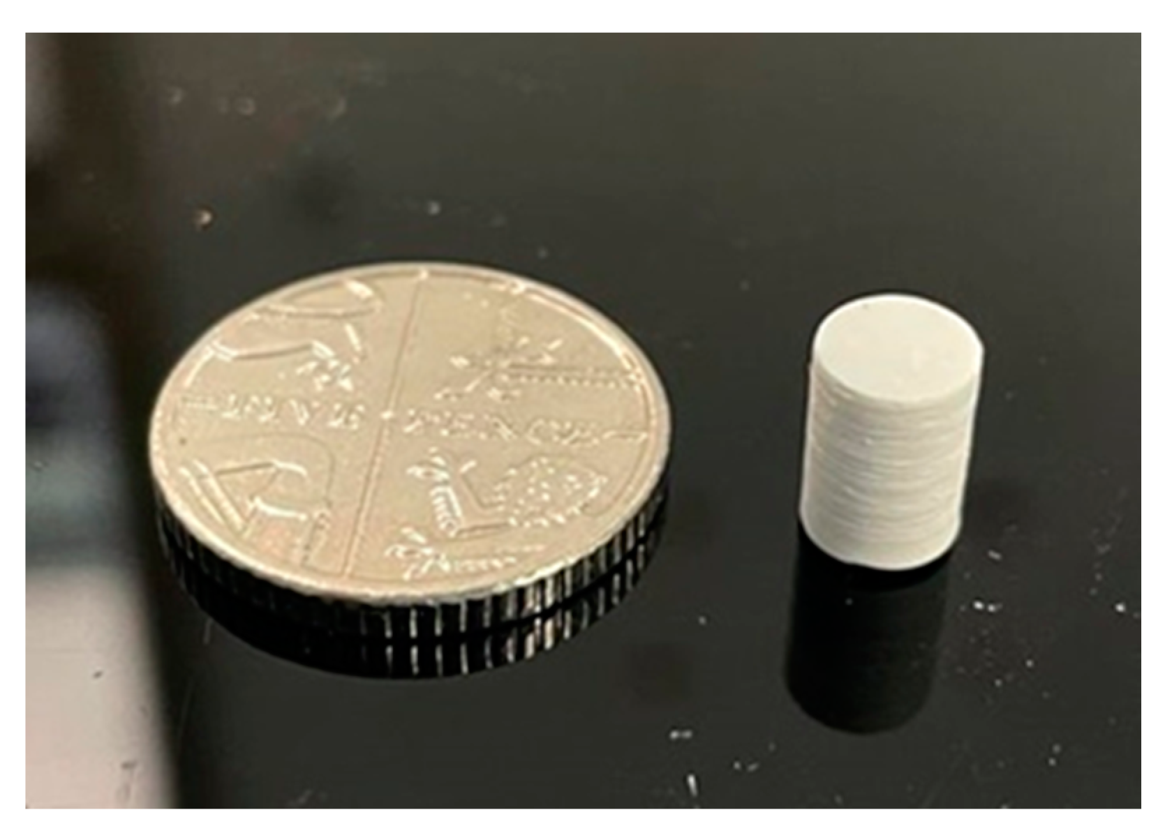
A number of cylinders with a diameter of 5 mm and height of 10 mm were printed along the z-axis with a layer thickness of 25 µm and an energy density of 20.16 mJ/cm2 (Figure 1). The printed parts were detached from the building plate and cleaned by using compressed air and dibasic ester (Sigma Aldrich, Gillingham, UK).
2.3. Debinding Cycle
A crucial step in the post-treatment of the 3D printed parts is the removal of the photopolymerisable resin from the interspace of the ceramic particles. During the debinding process, as the temperature rises, the organic components in the green body decompose into gas molecules, which diffuse or penetrate into the surface of the green body and, in the end, get out of it while leaving behind voids inside the now brown body. Thermogravimetric (TG) and Differential Scanning Calorimetry (DSC) analyses were carried out on a SDT NETZSCH STA with a heating rate of 5 °C/min and were used to identify the rapid mass loss of the green body printed by the DLP process. The selected debinding cycle was then performed in a tube furnace (TSH/1S/75/450, Elite Thermal Systems Ltd., Market Harborough, UK).
2.4. Sintering Cycles
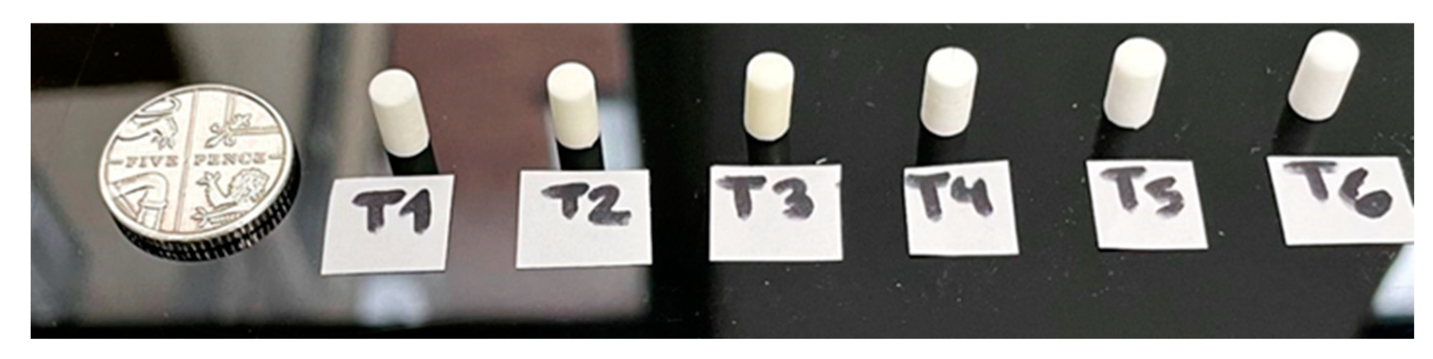
Sintering experiments were carried out at different dwell temperatures and dwell times in order to analyse density developments and shrinkages of the DLP printed cylinders. Six different sintering cycles were performed as detailed in Table 2; the respective sintered demonstrators are as shown in Figure 2. Sintering cycles were chosen in line with guidelines that can be widely found in the literature and within the workability window of the available sintering furnace, whose maximum operating temperature was 1700 °C. In particular, the lowest sintering temperature of 1540 °C was selected as it was the sintering temperature adopted by the powder supplier. In the end, three dwell temperatures, ranging from 1540 °C to 1650 °C, and two different holding times were selected, while fixing the heating rate at 3 °C/min.
The diameter and height dimensions of the green, brown, and sintered samples were collected. Four samples were fabricated for each sintering trial, and the average values of diameters and heights, together with the correspondent standard deviations, were reported. In addition, SEM pictures at the green, brown, and sintered stages were taken to reveal the surface evolution.
2.5. Numerical Modelling
In order to predict the behaviour of the alumina ceramic samples undergoing different sintering cycles, a finite element model was developed using the ABAQUS software and user-defined subroutines. The FEM code is based on thermo-viscoelasticity theory, and thus, takes its constitutive equations from it. Variables such as surface tension energy, shear and bulk viscosity, and average grain dimension need to be taken into account. From a macroscopic point of view, the material is believed to behave as a continuum and, consequently, based on the abovementioned thermo-viscoelastic model, the total strain rate is given by the addition of three different components, i.e., elastic, thermal, and viscous ones [28]. Therefore,
Consequently, the constitutive equation assumes the following aspect:
where
where α is the thermal expansion coefficient, T is the temperature, is the surface energy [35], r0 is the particle radius at the reference temperature, ηs is the viscous shear modulus, ηb is the viscous bulk one, σs is the sintering stress module, β is a parameter related to the powder morphology, and is the initial brown relative density—calculated to be averagely for the produced brown parts—all of which are strictly connected to microscopical properties and functions of porosity and temperature. Thus, Olevsky’s model [36] is adopted for estimating the shear and the bulk viscosities after calculating the apparent viscosity η via an Arrhenius-type equation tailored to Al2O3 characteristic properties [37]:
while in regard to grain growth, a cubic law was adopted [38] as reported below:
where η0 is a pre-exponential material-dependent constant, Qv is the activation energy for the viscous flow [37], G0 is the initial grain size assumed to be equal to the average particle size G0 = 800 nm, t is time, K0 is a pre-exponential material-dependent constant, Q = 640 kJ mol−1 is the activation energy for grain growth for normal sintering conditions [38], R is the universal gas constant, and T is the temperature in Kelvin. The Arrhenius equation is deemed to be increasingly more accurate as the material approaches its liquidus temperature, such as at high sintering temperatures. The model evaluates the relative density at every increment as per the mass conservation Equation (7) based on the current values of the deformations calculated via the constitutive Equations from (1) to (6). Hence, the relative density value is updated and continuously changes through the simulation, changing the material properties and affecting the subsequent deformations that determine the new value of relative density for the following increment. As a result, the relative density evolution is estimated and, in the end, the final sintered relative density predicted.
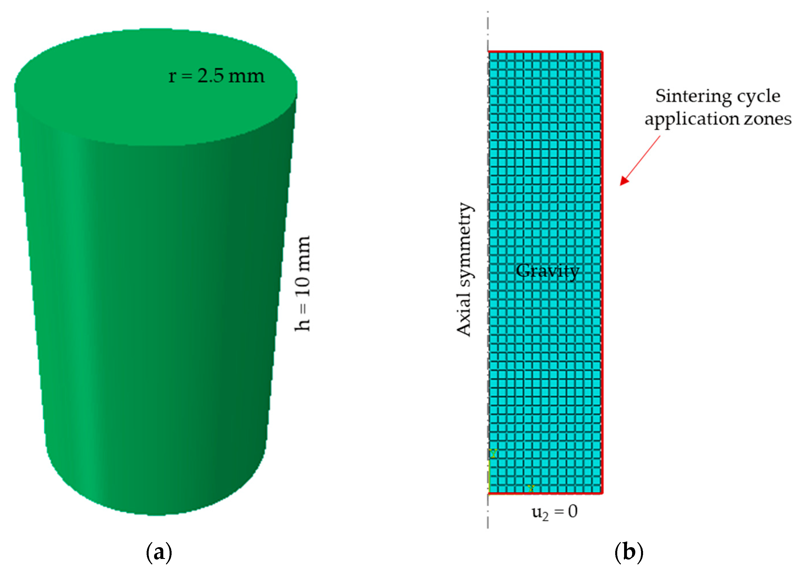
The thermal expansion coefficient, specific heat, and thermal conductivity were inputted into the finite element model as a function of temperature, while Young’s modulus and Poisson’s coefficient were functions of both density and temperature defined via subroutine [39,40]. Therefore, the material properties modifications due to the temperature changes during the sintering cycles were taken into account. Gravity was considered and axial symmetry exploited to reduce the computational effort, while movements along the negative z-axis were impeded at the lower base of the cylinder and the sintering cycles were applied directly to the outer surface of the cylinder itself (Figure 3).
3. Results and Discussion
3.1. Slurry Characterisation and Binder Removal
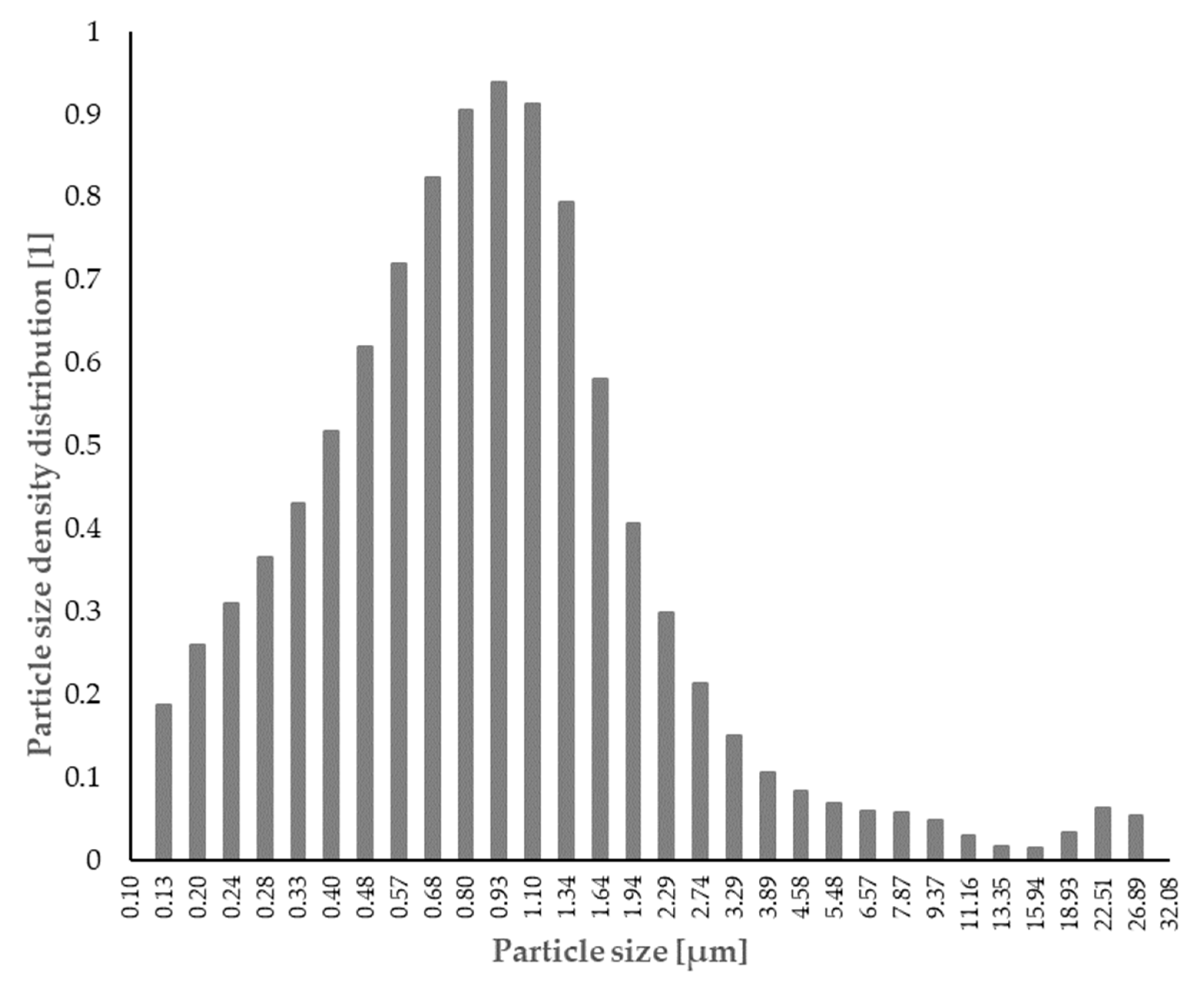
The properties of the alumina powder are shown in Table 3. The estimated mean particle size D50 is 0.80 µm, the theoretical density is 3.95 g/cm3, and the chemical impurities percentage is lower than 0.2% (Sympatec GmbH, Clausthal-Zellerfeld, Germany). The resulting powder distribution can be observed in Figure 4.
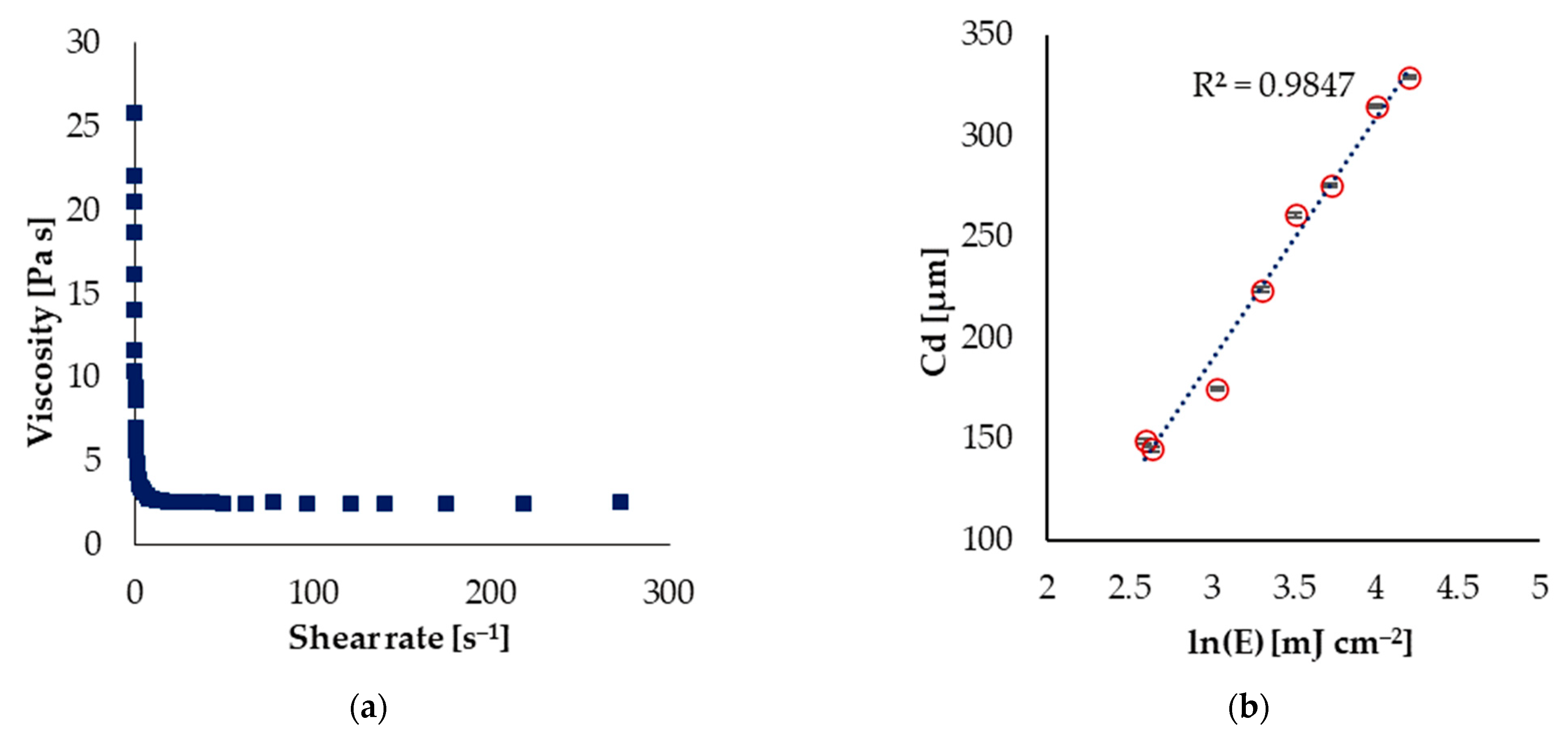
The rheology of the slurry is shown in Figure 5a. The prepared slurry shows a shear-thinning behaviour, in that a decreasing dynamic viscosity can be observed with the increase in the shear rates. Shear-thinning behaviour is highly desirable in stereolithography processes because it can allow the satisfactory spreading of thin layers; thus, a homogeneous green microstructure can be achieved. The shear rate working window for the adopted DLP machine ranges from 10 to 300 s−1, where, in this range, the dynamic viscosity has a stable and constant value. The curing behaviour of the slurry, which is characterised by the cure depth, depth sensitivity, and critical energy, was also investigated by exposing a single layer at various exposure energies to establish the critical exposure energy and depth of penetration. The slurry was degassed in a vacuum degasser for 10 min before measurement to eliminate air bubbles and decrease the inhibition of the polymerization. A checkboard design was projected onto the photopolymerizable resin layer and, after removing the single layer from the foil, the thickness of the cured material was measured using a portable micrometre. The average cure depth was determined by performing a total of three measurements [34]. It can be noted that the cure depth increases linearly with the logarithm of incident energy, which is consistent with the Lambert–Beer model of the SL process for cure depth.
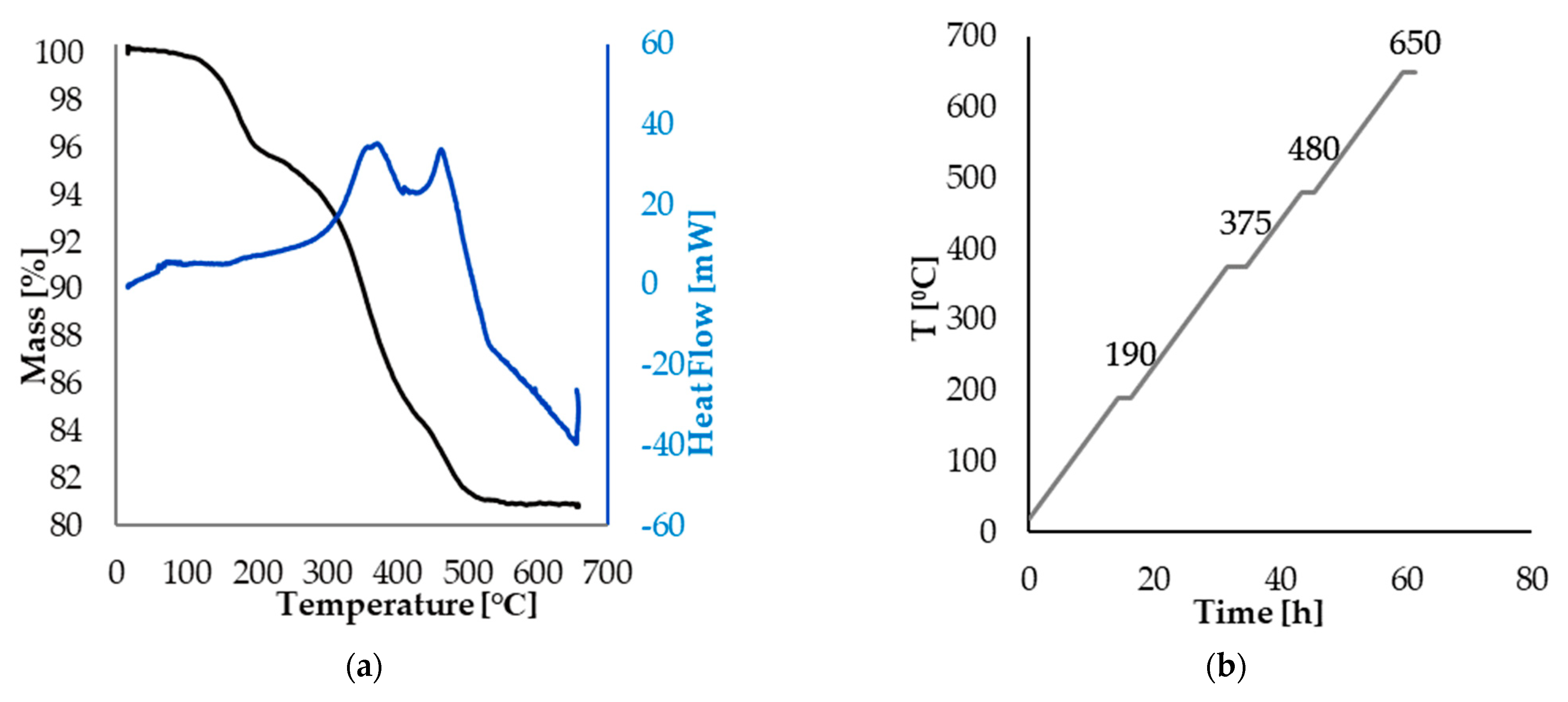
The TGA-DSC analysis of the green body revealed information on the decomposition behaviour of the organic matter in line with the changing temperature (Figure 6a). Two substantial exothermic peaks were observed at around 375 °C and 480 °C. The major weight loss, as shown by the TG curve, is observed from 190–480 °C with a total mass loss of 19.18%. Based on these data, the debinding regime was determined. Detailed temperature settings of the debinding process are shown in Figure 6b. The temperature was raised from room temperature to 190 °C and the dwell time at this first temperature setpoint was 2 h. Following this, the temperature was increased to 375 °C and maintained for 3 h to decompose the organics slowly and, consequently, relieve the thermal stresses on the ceramic parts. Subsequently, the system was heated to 480 °C and held at this temperature for 2 h. Finally, the temperature was gradually brought to 650 °C to eliminate any organic residual; kept for 2 h; and, in the end, cooled to room temperature. The heating rate of the whole debinding process was controlled and fixed at 0.2 °C/min.
3.2. Sintered Samples Characterisation and Numerical Model Validation
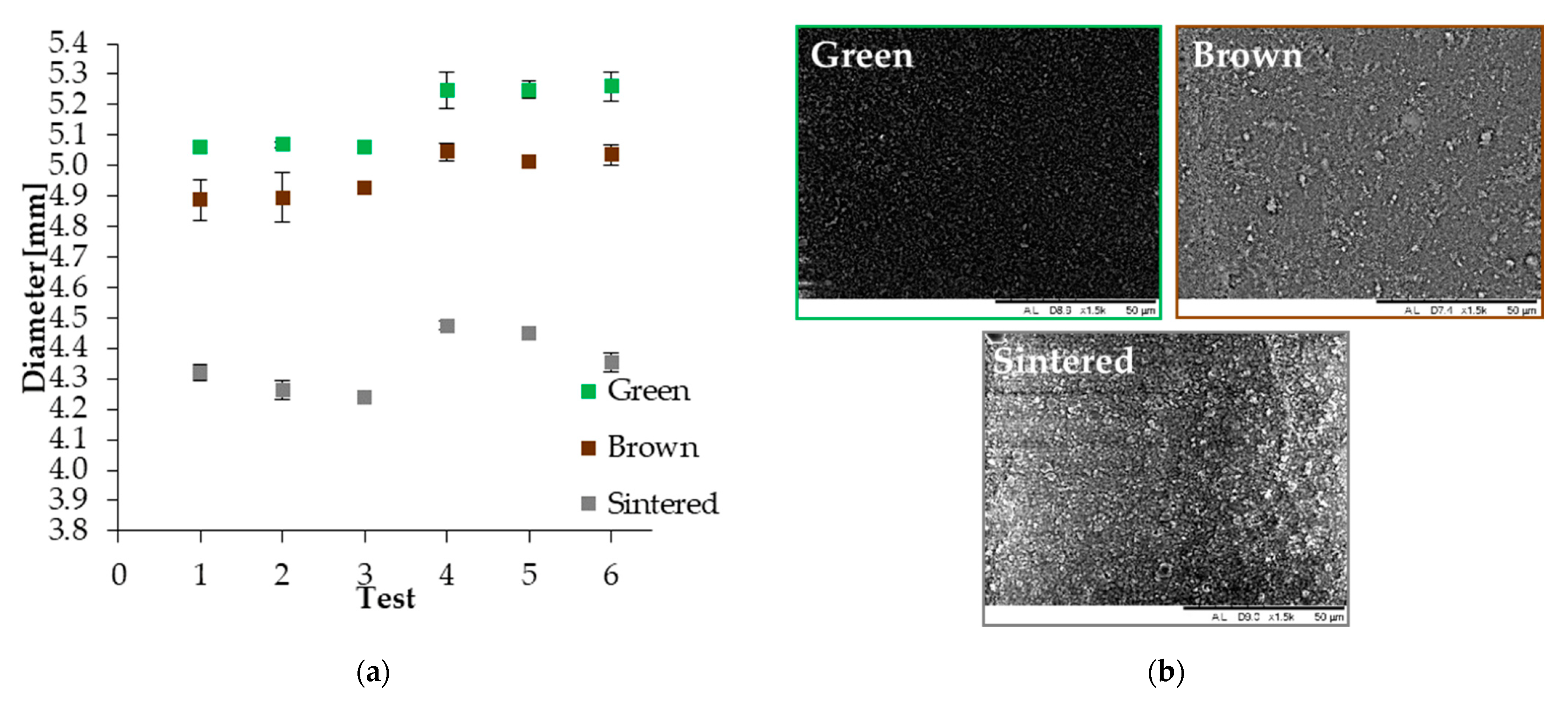
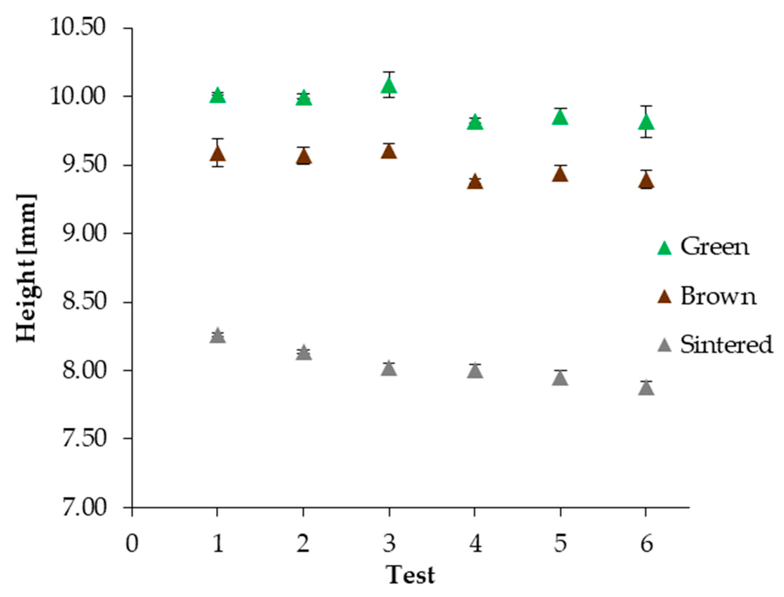
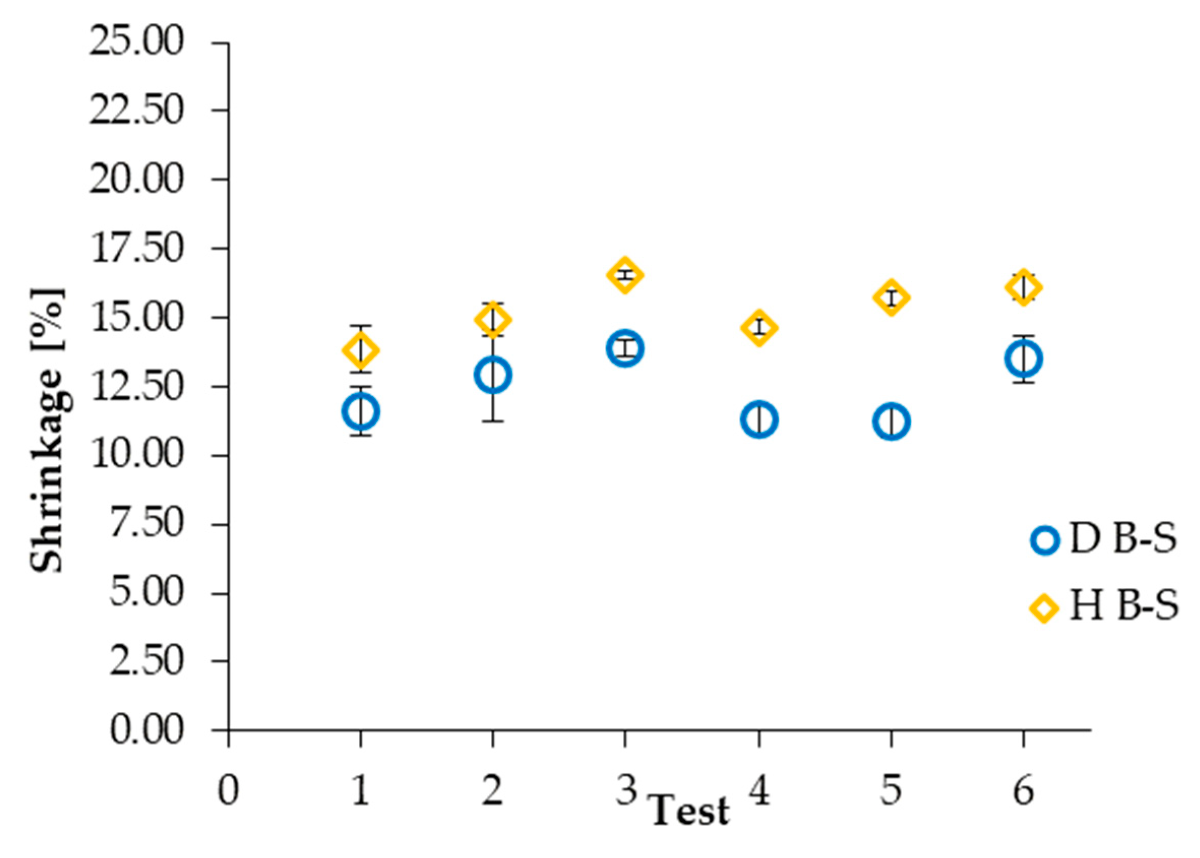
In Figure 7a, the average value for diameters with the corresponding standard deviations are plotted for each sintering trial. SEM pictures of the green, brown, and sintered stages were also taken, and, in Figure 7b, there is an example of the surface evolution detected by SEM for one of the trial T1 samples. In addition, the height change across the different processing steps can be seen in Figure 8. As can be observed, while both the geometrical features have similar modifications from the green stage to the brown one, the behaviour is different from the brown stage to the sintered one. In fact, the reduction in dimension is more relevant in terms of height rather than in terms of the diameter, resulting in a slight difference in the aspect ratio of the cylinders.
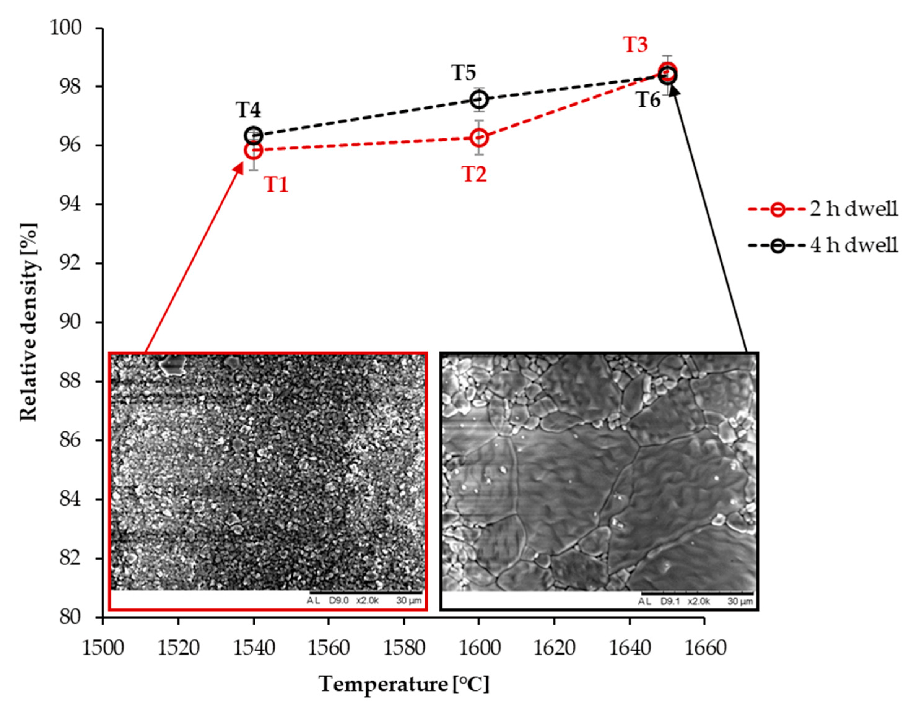
This is made more evident when comparing the shrinkages (Figure 9). In fact, the shrinkage along the axial dimension is more pronounced than the one measured along the radial dimension. This is due to the nature of the DLP printing working principle itself [41,42]: while on the layer plane, the material behaviour can be assumed to be isotropic if the used slurry had been thoroughly homogenised; along the building direction, more factors such as an optimal layer recovery influence the homogenisation of the material and, consequently, the material behaviour along it. Moreover, the final relative density obtained for the sintered samples, together with SEM images taken for trial 1 and trial 6, are shown in Figure 10 and categorised in terms of dwell time. As can be seen, longer holding times lead to a more pronounced grain growth. Additionally, when comparing tests conducted at the same temperature but different dwell times, it has been noticed that longer dwell times—as it could be possibly expected—corresponded with slightly higher grain dimensions. However, although trials T2 and T5 seem to behave slightly differently from the others, taking into consideration the error bars, it may be concluded that the effect of the dwell temperature is more relevant than the one of dwell time in terms of the final relative density of the sintered samples, in line with the literature findings [17,18,19].
To further prove what was mentioned earlier regarding the intrinsic anisotropy of the process, two dilatometry tests were conducted following the sintering parameters of trial T1. The dilatometer could only measure the shrinkage along the axial dimension; so, in order to investigate the anisotropy of the process, two different printing patterns were adopted (Figure 11): in the first case, the shrinking behaviour of a vertically printed sample was tested and a value of 17% was obtained; in the second, however, the sample was printed horizontally, so that the dilatometer could test the shrinkage behaviour of the layer rather than across the layers. As expected, the latter showed a different shrinkage value of 12%, although it also has to be mentioned that the number of layers axially exposed to the dilatometry test in this configuration, closely correlated to the shrinkage along the z axis, is lower than that in the former one.
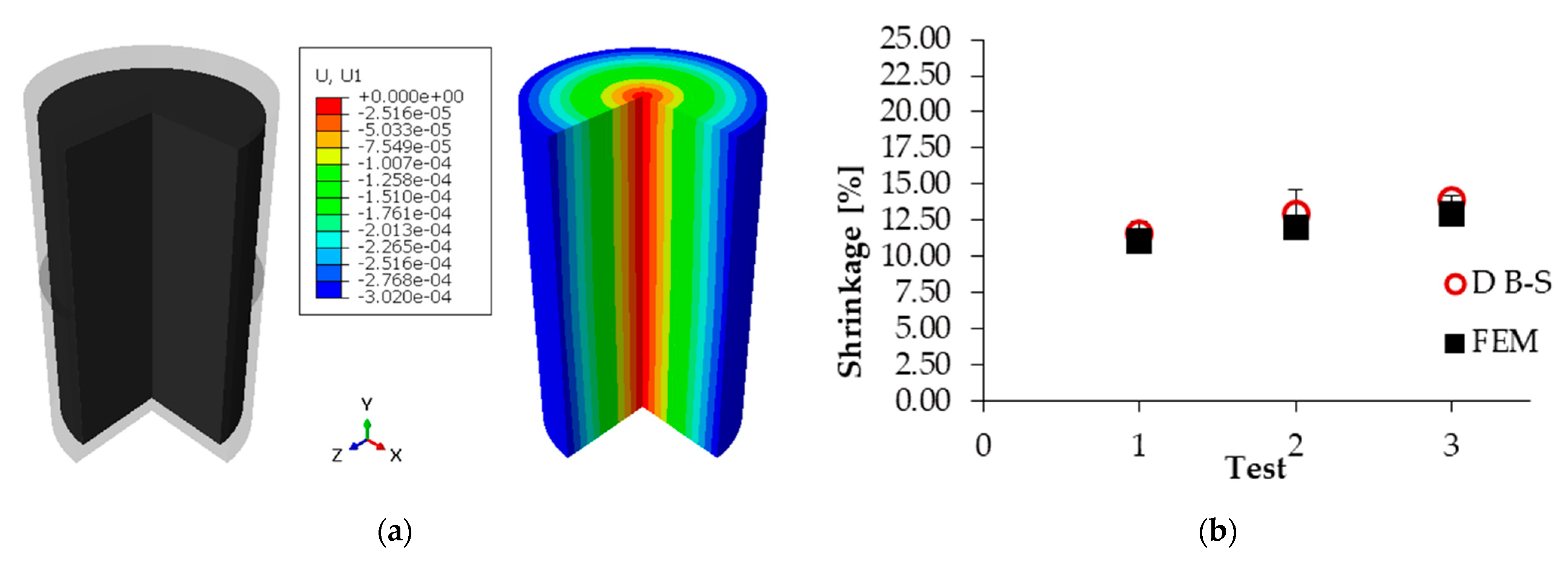
In Figure 12, the predicted displacement and shrinkages along the radial dimension obtained from the FEM are shown for the 2 h dwell time trials and compared with the experimental results. Only radial shrinkages are considered at this time, since the model is not able to take into account anisotropic behaviours. Following a slight expansion in the initial stages of the heating curve, where the expansion effect is more relevant than the sintering one, the cylinder begins to shrink as the temperature increases, reaching maximum shrinkage at the end of the dwell time. The areas in red are meant to indicate the zones with the minimum displacement, while the blue ones indicate the maximum displacement. Figure 12b, instead, shows that there is a close match between the experimental and numerical data on the part of the finite element model, although further improvement may be achieved by the introduction of anisotropy into the model.
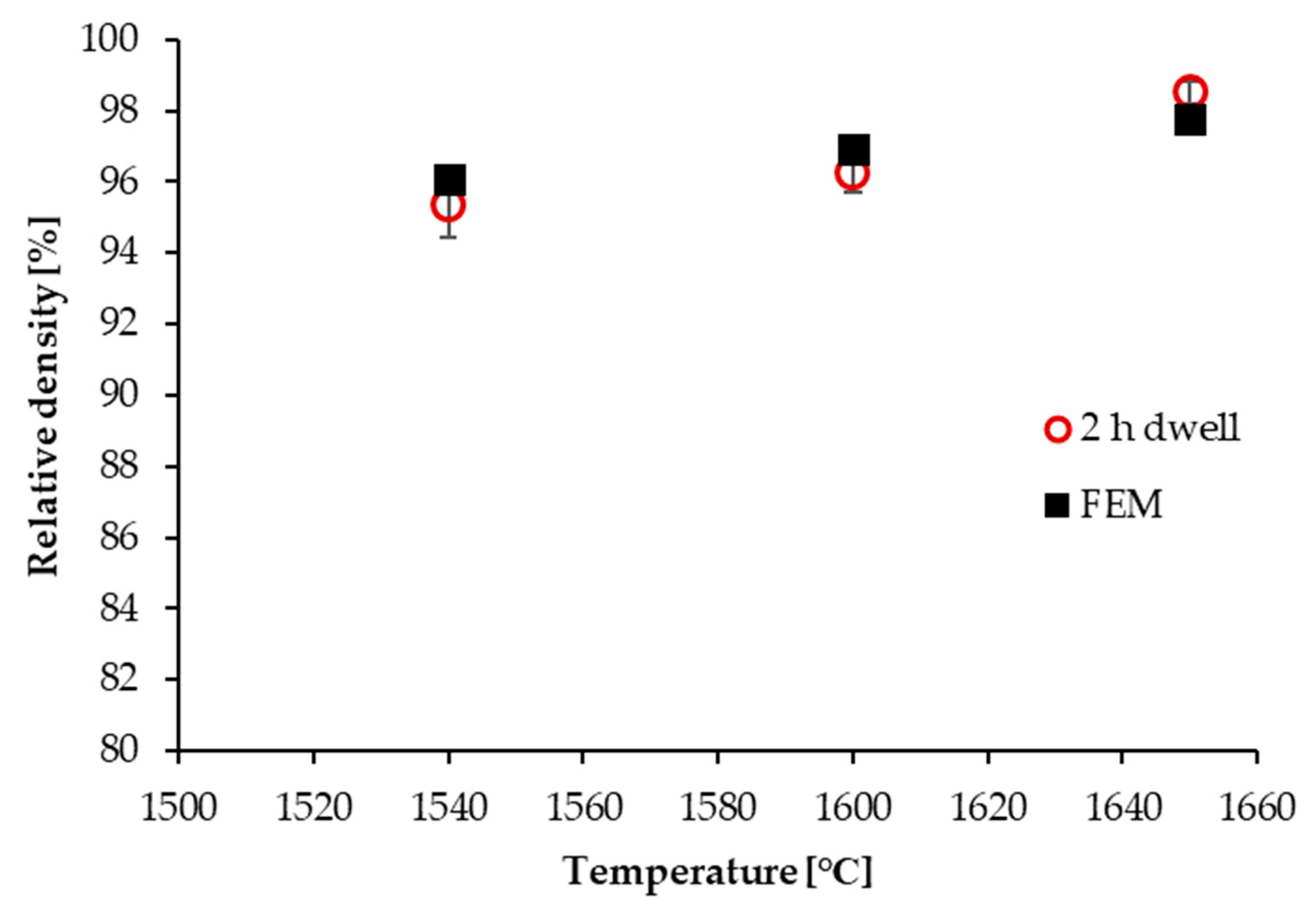
Final relative density was also estimated using the model. In Figure 13, the graph reports the comparison between the experimental results and the simulations. A good match between experiments and modelling can be observed: the model is able to predict the final relative density with a maximum of 2% error in either positive or negative directions. However, in the case of the relative density, the importance of taking into account a different shrinkage along the axial dimension tends to be of higher relevance as the dwell temperature increases; this is demonstrated by the fact that the FEM underestimates the final relative density at the highest dwell temperature according to the experimental results. In fact, by underestimating the axial shrinkage, the final volume of the simulated sample is higher and, consequently, the resulting estimation of the density is lower than the one obtained from the experimental trials.
4. Conclusions
A finite element model was developed exploiting a user-defined subroutine to simulate the thermomechanical behaviour of a simple cylindrical geometry undertaking specific sintering process schedules. A high-solid-loading, low-viscosity alumina slurry with suitable curing characteristics was prepared, and cylindrical samples were additively manufactured using Digital Light processing. DSC/TGA measurements revealed the appropriate binder removal regime. Several different experimental trials involving sintering of the cylindrical samples were conducted, and subsequent measurements and tests revealed that a certain degree of anisotropy could be detected in the DLPed samples. In fact, dilatometry tests suggested that anisotropic behaviour can be observed in the sintered samples, showing different shrinkage between the building direction and the layer plane. The FE model shows good agreement with the experimental results. In particular, numerical data demonstrate a close match between the predicted shrinkage and the relative density, with less than a 2% mismatch between the experimental results and simulations, suggesting that the model can be used for further optimisation of the sintering processes of alumina. In general, the FEM is able to predict the relative density evolution; therefore, it can be used to optimise sintering processes. However, the model is not able to take into account any anisotropy, something that is more evident as dwell temperatures increase. Consequently, future work should be directed to the integration of anisotropy in the evaluation of shrinkage and the relative density of the sintered bodies.
Author Contributions
Conceptualization, methodology, validation, investigation, M.D.L. and N.K.; software, formal analysis, data curation, writing—original draft preparation, visualization, M.D.L.; writing—review and editing, N.K., U.M.A. and K.E.; supervision, U.M.A. and K.E. All authors have read and agreed to the published version of the manuscript.
Funding
The authors would like to thank the Manufacturing Technology Centre (MTC) for the financial support of Michele De Lisi’s PhD project (Manufacturing Technology Centre, United Kingdom: 881440).
Data Availability Statement
All data are provided within the article and the provided references.
Acknowledgments
M.D.L. thanks the University of Birmingham and the Manufacturing Technology Centre (MTC) for the award of a PhD scholarship.
Conflicts of Interest
The authors declare no conflict of interest.
References
- Gao, W.; Zhang, Y.; Ramanujan, D.; Ramani, K.; Chen, Y.; Williams, C.; Wang, C.; Shin, Y.; Zhang, S.; Zavattieri, P. The Status, Challenges, and Future of Additive Manufacturing in Engineering. Comput. Aided Des. 2015, 69, 65–89. [Google Scholar] [CrossRef]
- Hassanin, H.; El-Sayed, M.A.; Elshaer, A.; Essa, K.; Jiang, K. Microfabrication of Net Shape Zirconia/Alumina Nanocomposite Micro Parts. Nanomaterials 2018, 8, 593. [Google Scholar] [CrossRef] [PubMed] [Green Version]
- Chen, Z.; Li, Z.; Li, J.; Liu, C.; Lao, C.; Fu, Y.; Liu, C.; Li, Y.; Wang, P.; He, Y. 3D printing of ceramics: A review. J. Eur. Ceram. Soc. 2019, 39, 661–687. [Google Scholar] [CrossRef]
- Lu, B.; Li, D.; Tian, X. Development Trends in Additive Manufacturing and 3D Printing. Engineering 2015, 1, 85–89. [Google Scholar] [CrossRef] [Green Version]
- Ngo, T.D.; Kashani, A.; Imbalzano, G.; Nguyen, K.T.Q.; Hui, D. Additive manufacturing (3D printing): A review of materials, methods, applications and challenges. Compos. Part B 2018, 143, 172–196. [Google Scholar] [CrossRef]
- Jiang, C.P.; Hsu, H.J.; Lee, S.Y. Technical Development of Slurry Three-Dimensional Printer. IOP Conf. Ser. Mater. Sci. Eng. 2017, 235, 012010. [Google Scholar] [CrossRef] [Green Version]
- Roach, M.; Maines, E.; Wall, B.; Wall, C.; Lavin, J.M.; Whetten, S.R.; Evans, L.; Keicher, D. Mechanical Challenges of 3D Printing Ceramics Using Digital Light Processing (No. SAND2018-7035C); Sandia National Lab. (SNL-NM): Albuquerque, NM, USA, 2018.
- Varghese, G.; Moral, M.; Castro-García, M.; López-López, J.J.; Marín-Rueda, J.R.; Yagüe-Alcaraz, V.; Hernández-Afonso, L.; Ruiz-Morales, J.C.; Canales-Vázquez, J. Fabrication and characterisation of ceramics via low-cost DLP 3D printing. Bol. Soc. Esp. Ceram. Vidrio 2018, 57, 9–18. [Google Scholar] [CrossRef]
- Yoo, C.M.; Lee, C.H.; Shin, H.S.; Yeo, D.H.; Kim, S.H. Dispersion Optimization of Alumina Slurry with Variation of the Dispersant. J. Nanosci. Nanotechnol. 2019, 19, 1677–1681. [Google Scholar] [CrossRef]
- Zhang, K.; Xie, C.; Wang, G.; He, R.; Ding, G.; Wang, M.; Dai, D.; Fang, D. High solid loading, low viscosity photosensitive Al2O3 slurry for stereolithography based additive manufacturing. Ceram. Int. 2019, 45, 203–208. [Google Scholar] [CrossRef]
- Chen, Z.; Li, J.; Liu, C.; Liu, Y.; Zhu, J.; Lao, C. Preparation of high solid loading and low viscosity ceramic slurries for photopolymerization-based 3D printing. Ceram. Int. 2019, 45, 11549–11557. [Google Scholar] [CrossRef]
- Yang, F.; Zhu, M.Z. Fabrication of β-TCP Scaffold with Pre-Designed Internal Pore Architecture by Rapid Prototyping of Mask Projection Stereolithography. Mater. Sci. Forum. 2018, 921, 67–77. [Google Scholar] [CrossRef]
- Goswami, A.; Srivastava, G.; Umarji, A.M.; Madras, G. Thermal degradation kinetics of poly(trimethylol propane triacrylate)/poly(hexane diol diacrylate) interpenetrating polymer network. Thermochim. Acta 2012, 547, 53–61. [Google Scholar] [CrossRef]
- Wu, Z.; Liu, W.; Wu, H.; Huang, R.; He, R.; Jiang, Q.; Chen, Y.; Ji, X.; Tian, Z.; Wu, S. Research into the mechanical properties, sintering mechanism and microstructure evolution of Al2O3-ZrO2 composites fabricated by a stereolithography-based 3D printing method. Mater. Chem. Phys. 2018, 207, 1–10. [Google Scholar] [CrossRef]
- Zhou, M.; Liu, W.; Wu, H.; Song, X.; Chen, Y.; Cheng, L.; He, F.; Chen, S.; Wu, S. Preparation of a defect-free alumina cutting tool via additive manufacturing based on stereolithography—Optimization of the drying and debinding processes. Ceram. Int. 2016, 42, 11598–11602. [Google Scholar] [CrossRef]
- Johansson, E.; Lidström, O.; Johansson, J.; Lyckfeldt, O.; Adolfsson, E. Influence of resin composition on the defect formation in alumina manufactured by stereolithography. Materials 2017, 10, 138. [Google Scholar] [CrossRef] [PubMed] [Green Version]
- Yuan, C.S.; Wang, Z.J.; Zhi, Q.; Zhang, Y.M.; Wang, X.D.; Yang, J.F. The preparation and properties of alumina ceramics through a two-step pressureless sintering process. Mater. Sci. Forum. 2018, 922, 47–54. [Google Scholar] [CrossRef]
- Dhuban, S.B.; Ramesh, S.; Tan, C.Y.; Wong, Y.H.; Alengaram, U.J.; Teng, W.D.; Tarlochan, F.; Sutharsini, U. Sintering behaviour and properties of manganese-doped alumina. Ceram. Int. 2019, 45, 7049–7054. [Google Scholar] [CrossRef]
- Yang, Z.; Yin, Z.; Wang, D.; Wang, H.; Song, H.; Zhao, Z.; Zhang, G.; Qing, G.; Wu, H.; Jin, H. Effects of ternary sintering aids and sintering parameters on properties of alumina ceramics based on orthogonal test method. Mater. Chem. Phys. 2020, 241, 122453. [Google Scholar] [CrossRef]
- Liu, L.; Hou, Z.; Zhang, B.; Ye, F.; Zhang, Z.; Zhou, Y. A new heating route of spark plasma sintering and its effect on alumina ceramic densification. Mater. Sci. Eng. A 2013, 559, 462–466. [Google Scholar] [CrossRef]
- Curto, H.; Thuault, A.; Jean, F.; Violier, M.; Dupont, V.; Hornez, J.C.; Leriche, A. Coupling additive manufacturing and microwave sintering: A fast processing route of alumina ceramics. J. Eur. Ceram. Soc. 2020, 40, 2548–2554. [Google Scholar] [CrossRef]
- Ćurković, L.; Veseli, R.; Gabelica, I.; Žmak, I.; Ropuš, I.; Vukšić, M. A review of microwave-assisted sintering technique. Trans. Famena 2021, 45, 1–16. [Google Scholar] [CrossRef]
- Sun, Z.; Li, B.; Hu, P.; Ding, F.; Yuan, F. Alumina ceramics with uniform grains prepared from Al2O3 nanospheres. J. Alloy. Compd. 2016, 688, 933–938. [Google Scholar] [CrossRef]
- Zachariah, M.R.; Carrier, M.J. Molecular dynamics computation of gas-phase nanoparticle sintering: A comparison with phenomenological models. J. Aerosol Sci. 1999, 30, 1139–1151. [Google Scholar] [CrossRef]
- Zhu, H.; Averback, R.S. Molecular dynamics simulations of densification processes in nanocrystalline materials. Mater. Sci. Eng. A 1995, 204, 96–100. [Google Scholar] [CrossRef]
- Maździarz, M.; Rojek, J.; Nosewicz, S. Estimation of micromechanical NiAl sintering model parameters from the molecular simulations. Int. J. Multiscale Comput. Eng. 2017, 15, 343–358. [Google Scholar] [CrossRef]
- Rojek, J.; Nosewicz, S.; Maździarz, M.; Kowalczyk, P.; Wawrzyk, K.; Lumelskyj, D. Modeling of a Sintering Process at Various Scales. Procedia Eng. 2017, 177, 263–270. [Google Scholar] [CrossRef]
- Wawrzyk, K.; Kowalczyk, P.; Nosewicz, S.; Rojek, J. A constitutive model and numerical simulation of sintering processes at macroscopic level. AIP Conf. Proc. 2018, 1922, 030011. [Google Scholar] [CrossRef] [Green Version]
- Kovacev, N.; Li, S.; Zeraati-Rezaei, S.; Hemida, H.; Tsolakis, A.; Essa, K. Effects of the Internal Structures of Monolith Ceramic Substrates on Thermal and Hydraulic Properties: Additive Manufacturing, Numerical Modelling and Experimental Testing. Int. J. Adv. Manuf. Technol. 2020, 112, 1115–1132. [Google Scholar] [CrossRef]
- Essa, K.; Hassanin, H.; Attallah, M.M.; Adkins, N.J.; Musker, A.J.; Roberts, G.T.; Tenev, N.; Smith, M. Development and Testing of an Additively Manufactured Monolithic Catalyst Bed for HTP Thruster Applications. Appl. Catal. A Gen. 2017, 542, 125–135. [Google Scholar] [CrossRef] [Green Version]
- Hassanin, H.; Essa, K.; Elshaer, A.; Imbaby, M.; El-Mongy, H.H.; El-Sayed, T.A. Micro-Fabrication of Ceramics: Additive Manufacturing and Conventional Technologies. J. Adv. Ceram. 2021, 10, 1–27. [Google Scholar] [CrossRef]
- Khaji, Z.; Klintberg, L.; Barbade, D.; Palmer, K.; Thornell, G. Alumina-based monopropellant microthruster with integrated heater, catalytic bed and temperature sensor. J. Phys. Conf. Ser. 2016, 757, 012025. [Google Scholar] [CrossRef] [Green Version]
- Wang, S.F.; Zhang, J.; Luo, D.W.; Gu, F.; Tang, D.Y.; Dong, Z.L.; Tan, G.E.B.; Que, W.X.; Zhang, T.S.; Li, S.; et al. Transparent ceramics: Processing, materials and applications. Prog. Solid State Chem. 2013, 41, 20–54. [Google Scholar] [CrossRef]
- Kovacev, N.; Li, S.; Essa, K. Effect of the Preparation Techniques of Photopolymerizable Ceramic Slurry and Printing Parameters on the Accuracy of 3D Printed Lattice Structures. J. Eur. Ceram. Soc. 2021, 41, 7734–7743. [Google Scholar] [CrossRef]
- Shinagawa, K. Micromechanical modelling of viscous sintering and a constitutive equation with sintering stress. Comput. Mater. Sci. 1999, 13, 276–285. [Google Scholar] [CrossRef]
- Olevsky, E.A. Theory of sintering: From discrete to continuum. Mater. Sci. Eng. R Rep. 1998, 28, 41–100. [Google Scholar] [CrossRef]
- Wu, G. Modelling and Experimental Validation of the Viscosity of Liquid Phases in Oxide Systems Relevant to Fuel Slags. Ph.D. Thesis, Rheinisch-Westfälischen Technischen Hochschule, Aachen, Germany, 2015. [Google Scholar]
- Bae, S.I.; Baik, S. Sintering and grain growth of ultrapure alumina. J. Mater. Sci. 1993, 28, 4197–4204. [Google Scholar] [CrossRef]
- Dörre, E.; Hübner, H. Alumina: Processing, Properties, and Applications; Springer: Berlin/Heidelberg, Germany, 1984. [Google Scholar]
- Auerkari, P. Mechanical and Physical Properties of Engineering Alumina Ceramics; Technical Research Centre of Finland: Espoo, Finland, 1996. [Google Scholar]
- Zohdi, N.; Yang, R. Material Anisotropy in Additively Manufactured Polymers and Polymer Composites: A Review. Polymers 2021, 13, 3368. [Google Scholar] [CrossRef]
- Monzon, M.; Ortega, Z.; Hernández, A.; Paz Hernández, R.; Ortega, F. Anisotropy of Photopolymer Parts Made by Digital Light Processing. Materials 2017, 10, 64. [Google Scholar] [CrossRef] [Green Version]
Figure 1.
Digital Light Processed green sample.

Figure 2.
Sintered samples resulting from the different sintering trials.

Figure 3.
(a) Geometry inputted in the FEM software. (b) Applied boundary conditions.

Figure 4.
Particle size distribution of the Al2O3 powder.

Figure 5.
(a) Measured viscosity of the ceramic slurry. (b) Cure depth vs. energy density [34].
Figure 5.
(a) Measured viscosity of the ceramic slurry. (b) Cure depth vs. energy density [34].

Figure 6.
(a) TG-DSC curves of Al2O3 sample. (b) Details of the adopted debinding cycle.

Figure 7.
(a) Diameter dimension evolution. (b) SEM images of green, brown, and sintered T1 samples, respectively.
Figure 7.
(a) Diameter dimension evolution. (b) SEM images of green, brown, and sintered T1 samples, respectively.

Figure 8.
Height dimension evolution.

Figure 9.
Diameter and height shrinkage from brown to sintered bodies.

Figure 10.
Relative density evolution for 2 h and 4 h dwell at the end of cycles.

Figure 11.
(a) Dilatometry of the vertically printed sample. (b) Dilatometry of the horizontally printed sample.
Figure 11.
(a) Dilatometry of the vertically printed sample. (b) Dilatometry of the horizontally printed sample.

Figure 12.
(a) After sintering shape vs. translucent presintered shape (left) and predicted radial displacement (right). (b) Experimental shrinkage vs. FEM simulations.
Figure 12.
(a) After sintering shape vs. translucent presintered shape (left) and predicted radial displacement (right). (b) Experimental shrinkage vs. FEM simulations.

Figure 13.
Experimental relative density vs. FEM predictions.


Table 1.
Slurry composition.
| Starting Materials | Powder | Resin–Photoinitiator Mixture |
|---|---|---|
| Chemical composition | Dispersant pretreated Al2O3 | Monofunctional, difunctional, tetrafunctional monomer, plasticizer, photoinitiator |
| Mass percentage | 83 wt.% total | 17 wt.% total |
Table 2.
Sets of sintering experiments performed.
| T1 | T2 | T3 | T4 | T5 | T6 | |
|---|---|---|---|---|---|---|
| Dwell temperature (°C) | 1540 | 1600 | 1650 | 1540 | 1600 | 1650 |
| Dwell time (h) | 2 | 2 | 2 | 4 | 4 | 4 |
Table 3.
Properties of the Al2O3 powder.
| Particle Size Distribution | |||
| D10 (µm) | D50 (µm) | D90 (µm) | |
| 0.23 | 0.80 | 2.31 | |
| Theoretical density | |||
| 3.95 g/cm3 | |||
| Chemical composition 1 | |||
| Al2O3 (by difference) | 99.8 | ||
| Na2O | 0.07 | ||
| Fe2O3 | 0.02 | ||
| MgO | 0.05 | ||
| SiO2 | 0.03 | ||
| CaO | 0.02 | ||
| B2O3 | <0.005 | ||
| Surface area BET 1 | |||
| 8.9 m2/g |
1 Information provided by the supplier.
Publisher’s Note: MDPI stays neutral with regard to jurisdictional claims in published maps and institutional affiliations. |
© 2022 by the authors. Licensee MDPI, Basel, Switzerland. This article is an open access article distributed under the terms and conditions of the Creative Commons Attribution (CC BY) license (https://creativecommons.org/licenses/by/4.0/).
Share and Cite
MDPI and ACS Style
De Lisi, M.; Kovacev, N.; Attia, U.M.; Essa, K. Numerical Simulation of Sintering of DLP Printed Alumina Ceramics. Aerospace 2022, 9, 336. https://0-doi-org.brum.beds.ac.uk/10.3390/aerospace9070336
AMA Style
De Lisi M, Kovacev N, Attia UM, Essa K. Numerical Simulation of Sintering of DLP Printed Alumina Ceramics. Aerospace. 2022; 9(7):336. https://0-doi-org.brum.beds.ac.uk/10.3390/aerospace9070336
Chicago/Turabian StyleDe Lisi, Michele, Nikolina Kovacev, Usama M. Attia, and Khamis Essa. 2022. "Numerical Simulation of Sintering of DLP Printed Alumina Ceramics" Aerospace 9, no. 7: 336. https://0-doi-org.brum.beds.ac.uk/10.3390/aerospace9070336
Note that from the first issue of 2016, this journal uses article numbers instead of page numbers. See further details here.