Thermal Performance of Double-Sided Metal Core PCBs
by
 , and
, and
Mathew G. Pelletier
1,* ,
,
Stone C. Preston
2,
Jim A. Cook
3,
Kevin D. Tran
1,
John D. Wanjura
1 and
Greg A. Holt
1 1
Agricultural Research Services United States Department of Agriculture, Lubbock, TX 79415, USA
2
Department of Mechanical Engineering, Texas Tech University, Lubbock, TX 79409, USA
3
Department of Electrical Engineering, Texas Tech University, Lubbock, TX 79409, USA
*
Author to whom correspondence should be addressed.
AgriEngineering 2019, 1(4), 539-549; https://0-doi-org.brum.beds.ac.uk/10.3390/agriengineering1040039
Submission received: 6 September 2019
/
Revised: 6 November 2019
/
Accepted: 7 November 2019
/
Published: 13 November 2019
(This article belongs to the Special Issue Robotics and Automation Engineering in Agriculture)
Abstract
:Thermal management in printed circuit boards is becoming increasingly more important as the use of LEDs is now widespread across all industries. Due to availability of the preferred electronic LED current drivers and system constraints for a machine-vision application, the design dictated the need for a double-sided metal core printed circuit board (MCPCB). However, design information for this relatively new MCPCB offering is sparse to non-existent. To fill-in this missing information in the literature, experiments were conducted where LEDs were arranged on a double-sided metal core printed circuit board (MCPCB), and their impact on the board temperature distribution was tested in a static fan-less configuration where the first condition was at room temperature, 23 °C, and the second configuration was for a heated environment, 40 °C. Two MCPCB orientations were tested (vertical and horizontal). Additionally, several LED arrangements on the MCPCB were configured, and temperatures were measured using a thermocouple as well as with a deep-infrared thermal imaging camera. Maximum temperatures were found to be 65.3 °C for the room temperature tests and 96.4 °C for the heated tests with high temperatures found in near proximity to the heat sources (LEDs), indicating less than ideal heat-conduction/dissipation by the MCPCB. The results indicate that the double-sided MCPCB topology is not efficient for high thermally loaded systems, especially when the target is a fan-less system. The results of testing indicate that for fan-less systems requiring high-performance heat-transfer, these new MCPCB are not a suitable design alternative, and instead, designers should stick with the more traditional single-sided metal-back PCB.
1. Introduction and Overview of the Research and Results of System Performance That This Technical Note Supports
Design information for a new thermally efficient printed-circuit-board, PCB, has been recently offered by PCB board houses. As PCB boards are now a commodity off-the-shelf order that is available from most PCB board manufacturers; designers have little to no control over the manufacturing process. Hence, control is basically limited to component placement and types of component packages that are mounted onto the PCB board, per normal PCB manufacturing design process. A recent new design offering from PCB board houses are metal-cored PCB boards, MCPCB, of which the manufacturers are claiming high performance thermal heat transfer properties and which they promote as new options to consider where one needs a design that supports components mounted on both sides of the PCB. Giving the glowing recommendations from the PCB board houses, our initial impression was very favorable and led the authors to invest significant engineering resources into pursing the use of the MCPCB for one of their cotton contamination detection systems. The environment dictated a fanless design would be optimal, given the high dust levels, and due to the elevated ambient temperatures in these factories during the summer, the light-emitting-diode, LED, board required by the design would face significant thermal loading. These new MCPCB’s offer thermally efficient boards that are formed around a metal-core that is promoted by the board houses as having a built-in thermal heat-sink. While in theory this is logical and persuasive, there is however little to no design information available from the PCB board houses or in the published literature on double-sided metal-core PCB boards. This technical note details the thermal testing of a high-thermally loaded electronic design that was developed for the lighting sub-system of a machine-vision system that is targeted for use in an online real-time plastic contamination removal system for use in cotton gins.
LEDs are used across all industries in lighting, signaling and various other applications. Machine vision technologies typically use high-power LEDs to provide maximum contrast on features of interest [1]. However, the high-power LEDs that are used in applications such as this also produce a large amount of thermal energy. This thermal energy must be transferred out of the printed circuit board, (PCB), in order to maintain safe operating conditions for the LEDs and other board components. Because the life of the LED is directly affected by the temperatures present at the LED’s junction, between the silicon die and the LED’s component housing, ensuring adequate heat transfer away from the LED is vital to maximizing the lifespan of these components [2]. Increased temperatures not only affect the lifespan of the LED but also the performance. The luminous efficacy of the LED is decreased by 5 percent for every 10 °C rise in operating temperature [3]. The color of the light can also change as the temperature rises, which would impact applications with strict lighting requirements [4] such as in machine-vision applications. Typical PCB materials, such as FR4 (NEMA grade designation for glass-reinforced epoxy laminate material) and polyimide, have low thermal conductivities and do not sufficiently transfer heat [5]. One of the main ways of achieving adequate thermal management is the use of a metal-core printed circuit board, MCPCB, where the metal core has a high thermal-conductivity that readily transfers heat away from the sourcing component [6].
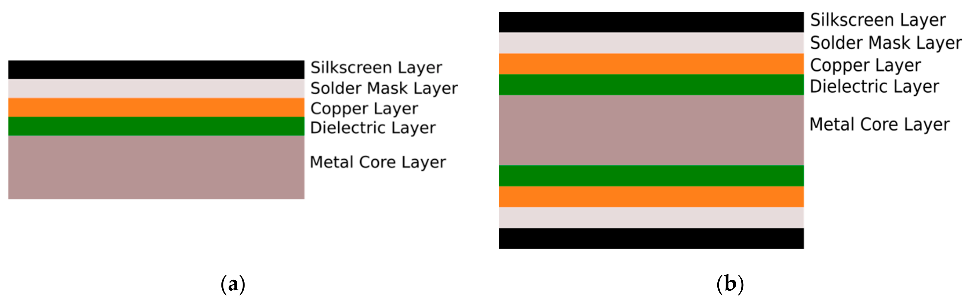
Numerous studies have been done regarding LEDs and heat transfer in single-sided MCPCBs. In this application, the exposed aluminum side of the MCPCB is typically mounted to a finned heat sink to help dissipate the LED generated heat. This approach, however, imposes the constraint that limits application to use only surface-mount components. The literature reports that the LED arrangement has been shown to affect the adequacy of heat transfer in single-sided MCPCBs [7]. In addition to LED arrangement, wire patterns have also been shown to affect the thermal behavior of PCBs [8]. The advantageous effects of the high thermal conductivities of the metals used in these single-sided MCPCBs have also been explored [9]. Algorithms for optimal heat sink placement for surface mount LED applications in single-sided MCPCBs have been developed [10]. Heat sink designs such as heat pipes [11] and finned LED holders [12] have been tested. The effects of forced convection via fans on single-sided MCPCBs have been analyzed [13]. Thermal management design criteria for LED arrays have been established [14]. In addition to experimentation, heat transfer in single-sided MCPCBs has been simulated using CFD packages [15]. However, most if not all of the current research uses a single-sided MCPCB stack-up similar to that shown in Figure 1a, a style which is limited to surface mount components only. This typical single-sided stack up allows for heat sinks to be attached to the highly conductive metal core bottom layer, which allows for good thermal management. Recent report utilizing computational fluid-dynamic analysis for single-sided LED thermal design reported utilizing various shapes of aluminum heat-sink for 60 LED’s mounted on a grid pattern [16]. Other notable fanless passive convective cooling research for single-sided LED thermal designs reported on experimentally confirmed computational fluid dynamic design that found significantly higher thermal heat transfer coefficients (2.2 degrees C W−1) for a vertical hollow cylinder versus a vertical chimney design [17]. Their research found typical temperature distribution to vary from 5–10 degrees C with a maximum temperature from 55–70 degrees C., with rise dependent upon heat sink design. Additional notable work on passive natural convection heat dissipation for rectangular finned heat sinks or various configurations is reported [18]. They found blockage of natural convective flow to be one of the dominant factors deteriorating heat transfer in rectangular fin designs. While the literature reports are clearly indicating effectiveness in thermal management is possible for fan-less single-sided PCB LED designs utilizing heat sinks, the single-sided design is limiting with regards to circuit design. To alleviate this, a new MCPCB design has recently become available; however, while the double-sided stack up of these new MCPCB’s (Figure 1b) provides the advantage for double-sided component placement, there is currently a lack of engineering thermal design information and literature regarding this double-sided stack-up. Hence, questions about the adequacy of heat transfer using this style of board remain unanswered for this new configuration where the metal core is insulated, and there is no easy means to attach a heat sink to the inner metal core. In addition to being unable to attach a heat sink, the intended application for this board does not allow for the use of fans, due to the deployment into a high-dust environment. Hence, the idea target design.
This research explores the new double-sided MCPCB stack-up option using a set of experiments that allows for thru-hole component placements, as shown in Figure 1b. In this report, we present a thermal analysis of experimental data taken of seven different LED arrangements on a double-sided MCPCB.
2. Materials and Methods
2.1. Materials
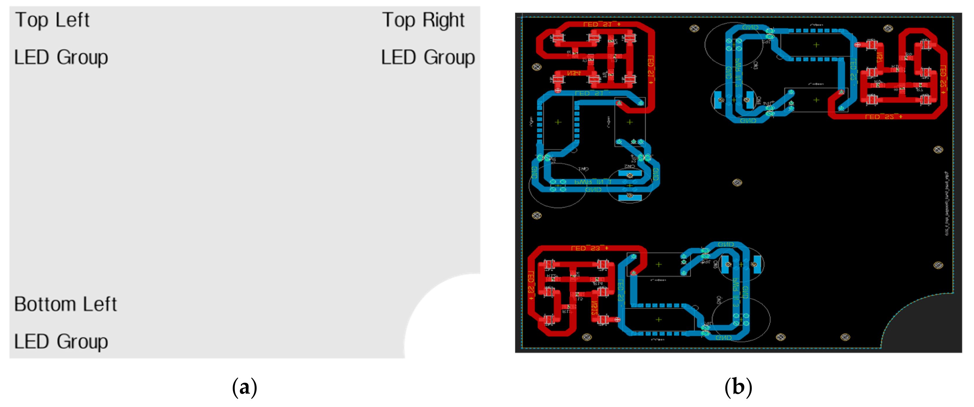
2.2. Location of LED and LED Drivers
This experimental protocol utilized the convention shown in Table 3 to refer to specific test configurations. [circuit traces shown in red are on the top-layer and traces in blue are on bottom-layer]
2.3. Experimental Methods
Two types of tests were performed during the experiment. Tests with the device in a 23 °C room (the room temperature test), and a test with the device in a heated and well insulated environment at 40 °C (the heated test). An insulated chamber was heated using hot soil to achieve a stable and consistent steady-state heat-source, HS, that provided a thermally stable temperature. The procedure for the room temperature test is shown below.
The experimental protocol for ambient room-temperature was as follows:
- Set power supply to 18 V, [turned off].
- Connect power supply leads to the active LEDs for given test.
- Using electrically isolated tape, secure thermocouple temperature probe to the PCB board near one of the LEDs that will be on [to verify thermal image temperature reading emissivity settings on IR imaging camera are correct].
- Turn the power supply on then
- At 1-min intervals, capture a thermal image of the board using the FLIR camera, and record thermocouple temperature reading
- Repeat step a until the board temperature stabilizes
The procedure for the heated tests was similar, with the exception that the PCB board was placed into an insulated chamber with large mass HS. The heated tests were done for vertical and horizontal board orientations with a target temperature of 40 °C.
3. Results
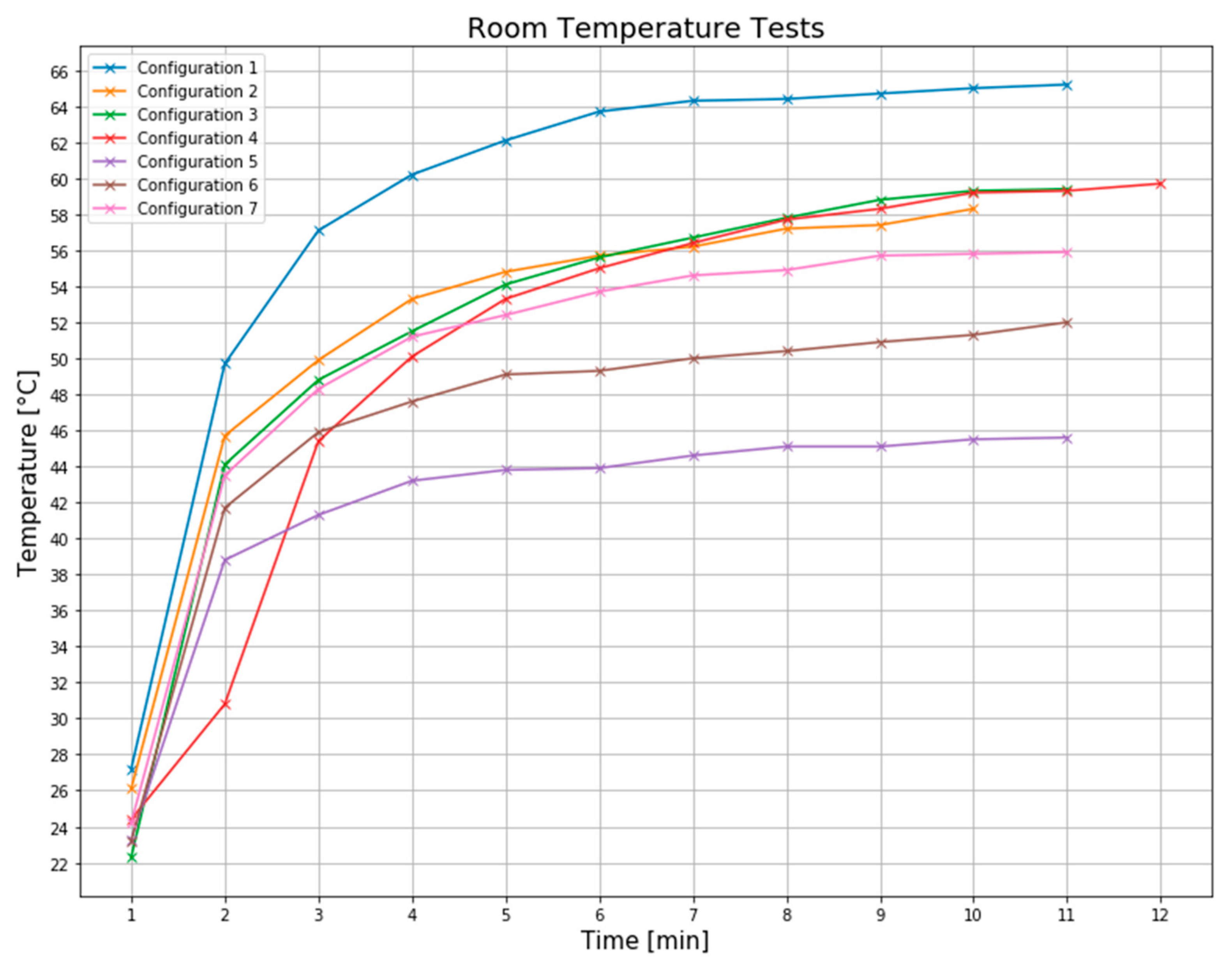
3.1. Room Temperature Tests
The results of the ambient room temperature tests are shown in Figure 3.
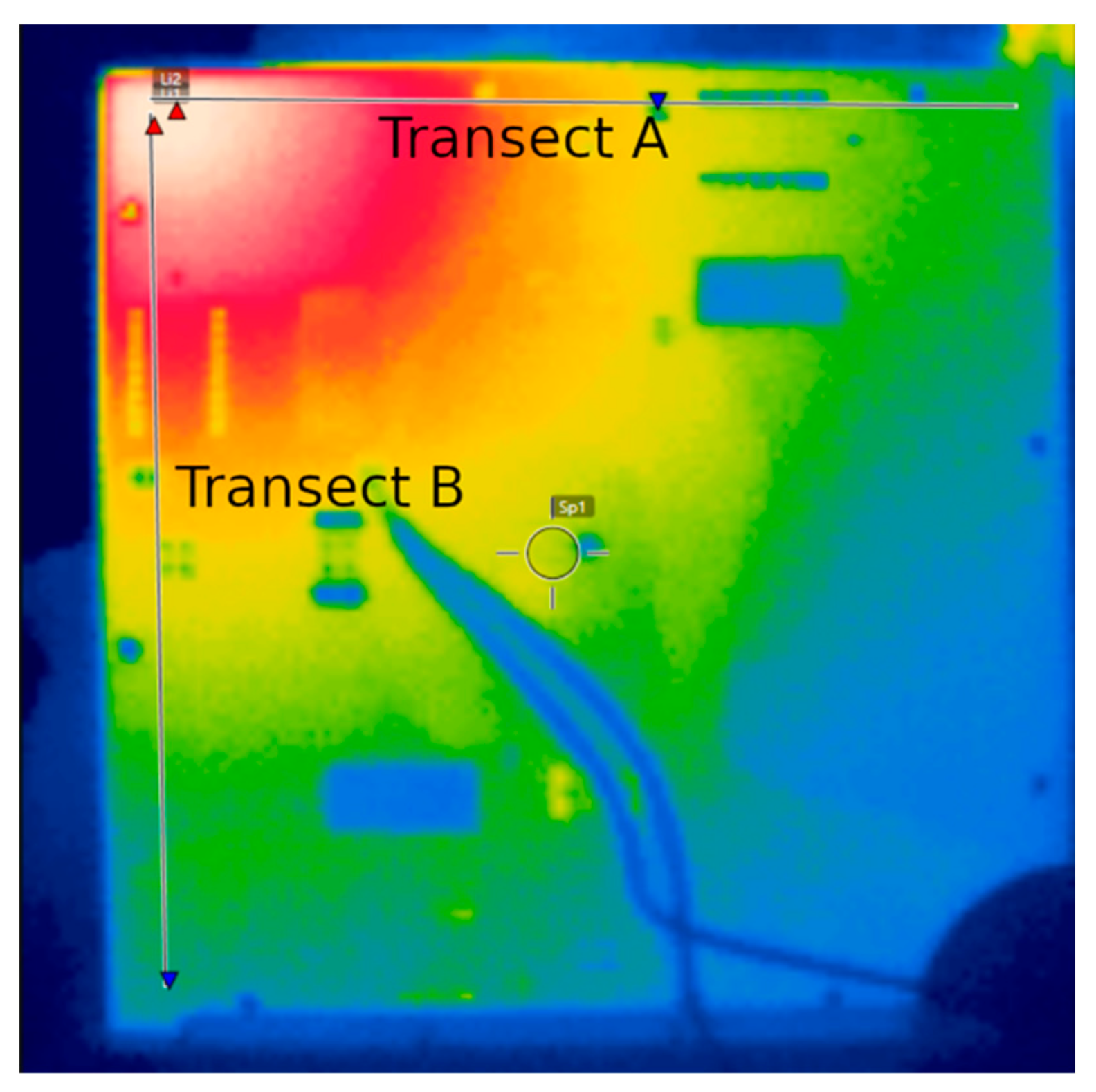
A thermal image of configuration 5 at the final time value of the room temperature test is shown in Figure 4.
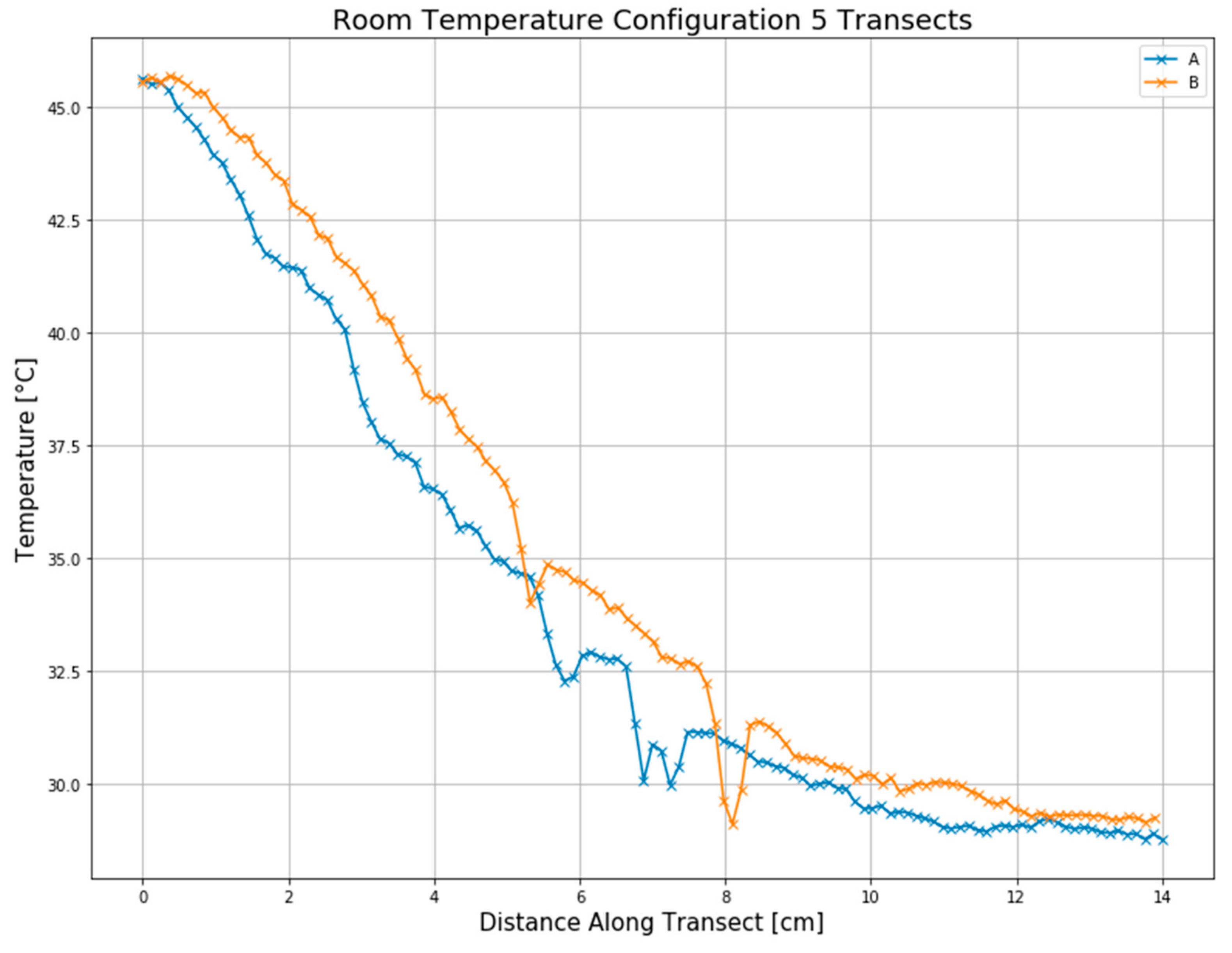
A plot of temperatures across the transects A and B, of Figure 4, is shown in Figure 5 for configuration 5.
Of interest for design purposes, for the transects shown in Figure 5, are the rapid drops in temperature with increasing distance from the LED heat source. This lack of heat transmission, by the double-sided MCPCB, results in highly localized hotspots on the circuit board which will likely lead to component failure. As the metal-core, in the MCPCB, is surrounded by insulating FR4 layers, there is not a convenient way to mount a heat-sink that could be used to augment thermal heat extraction. As such, this experiment shows the limitations of the double-sided MCPCB design.
3.2. Heated Tests
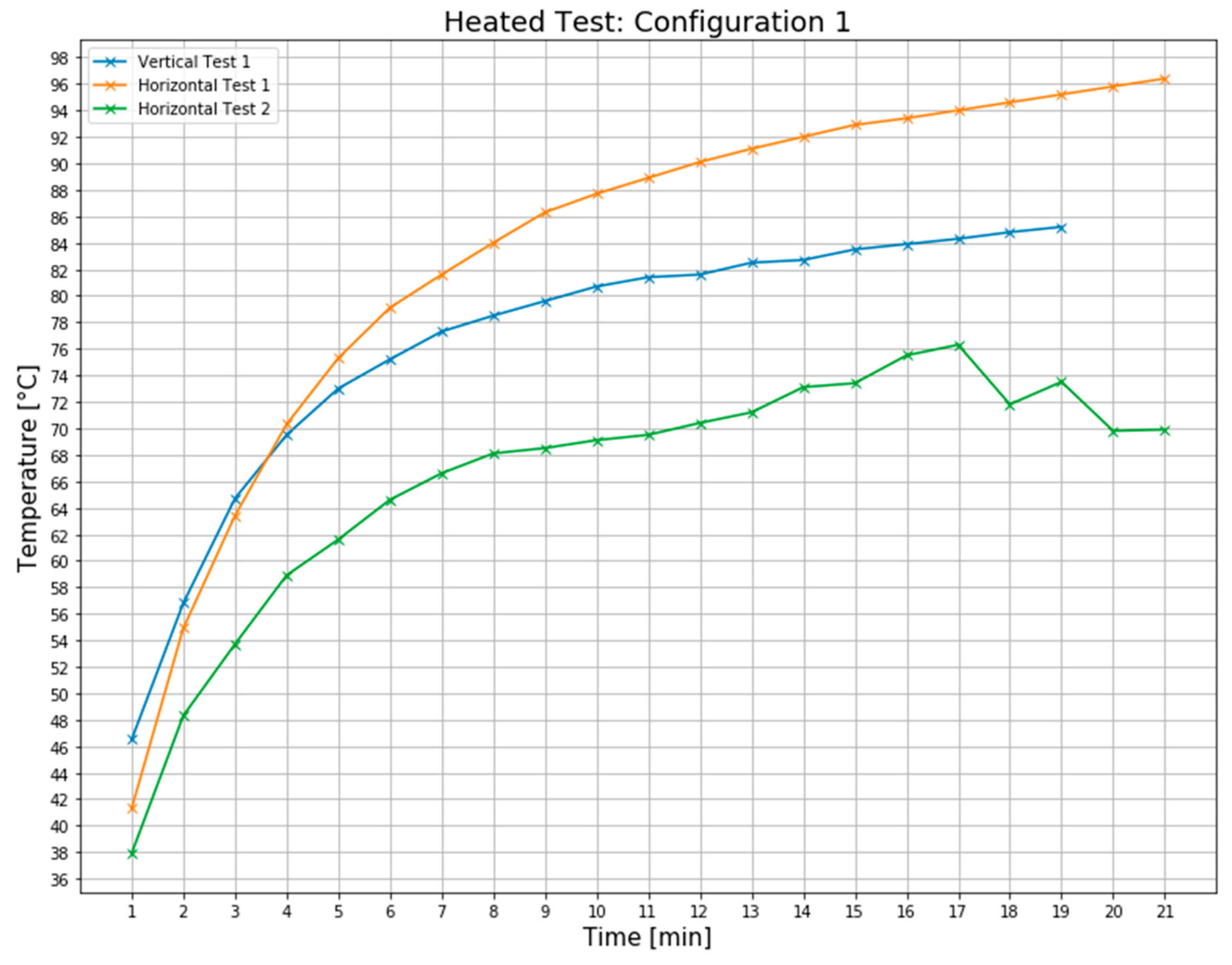
The results of the transient response, for configuration 1, heated room tests are detailed in Figure 6. An additional heated room test, Horizontal Test 2, was done for the horizontal orientation after the first two configuration 1 tests. This lower temperature results obtained for the Test 2 showed that the power output of the LEDs was significantly lower than the first tests indicating component failure due to the previous heated tests. As the target deployment room temperature for the design, of 40 °C, was the same as the heated room test temperature; these results provide conclusive evidence that this design would not be successful for an industrial deployment of a similarly configured system.
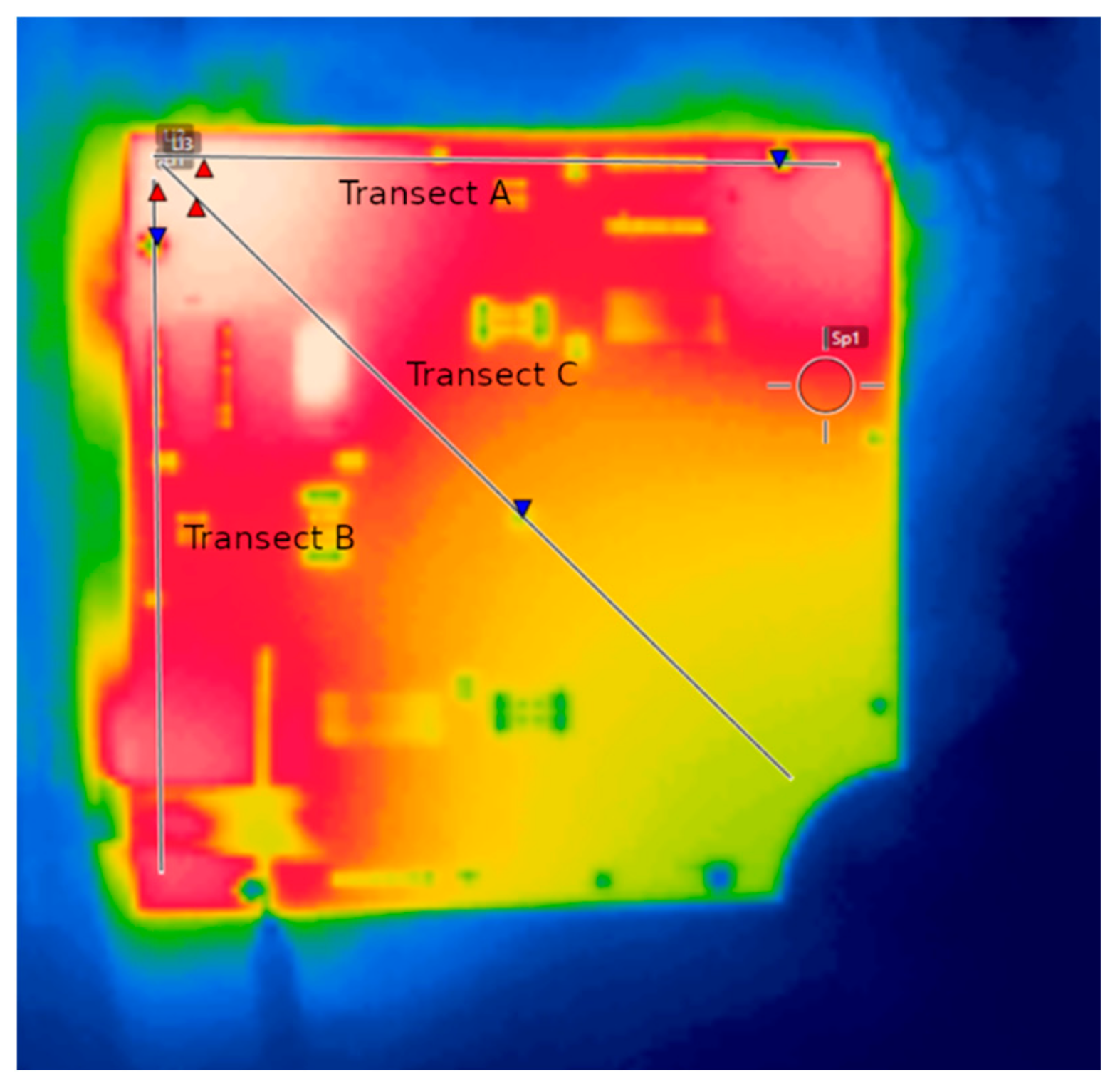
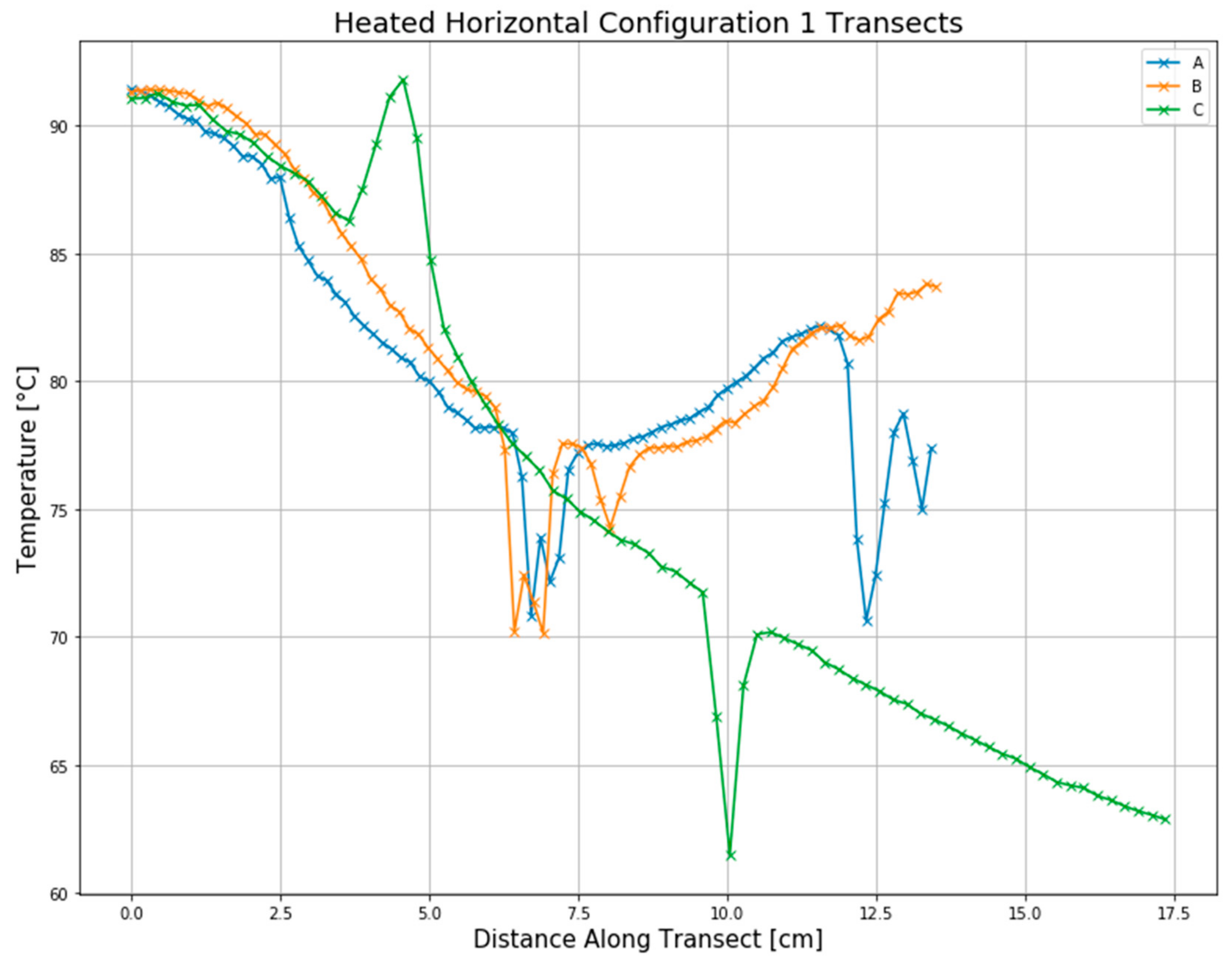
A thermal infrared temperature image captured at the final time value of the heated-room test for configuration 1 is shown in Figure 7, and a plot of the infrared image temperatures across the transects is shown in Figure 8. Of note again are the highly localized hotspots near the LED heat sources, indicating an insufficiency of the double-sided MCPCB to off-load heat from the LED sources to the cooler regions of the MCPCB.
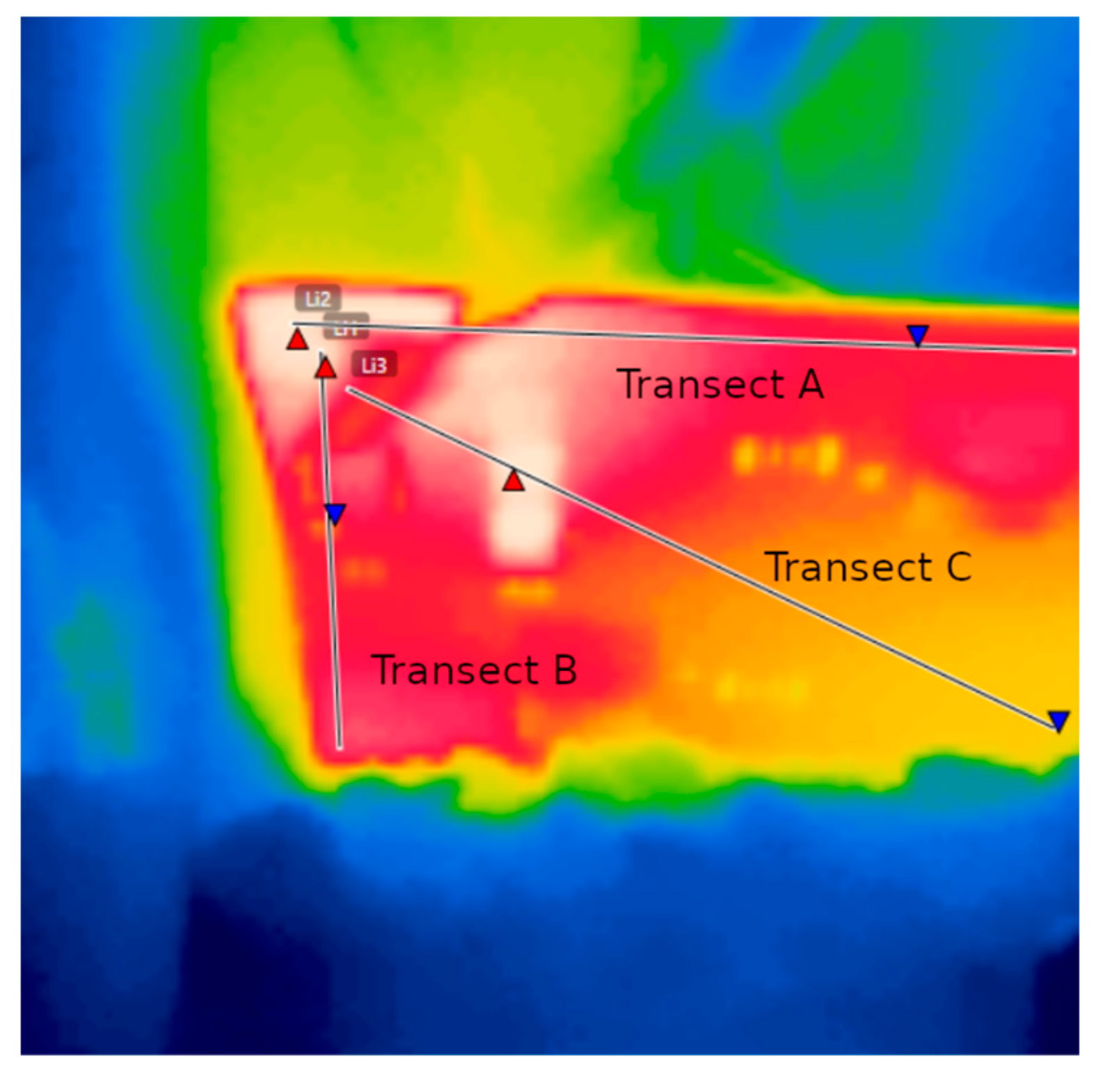
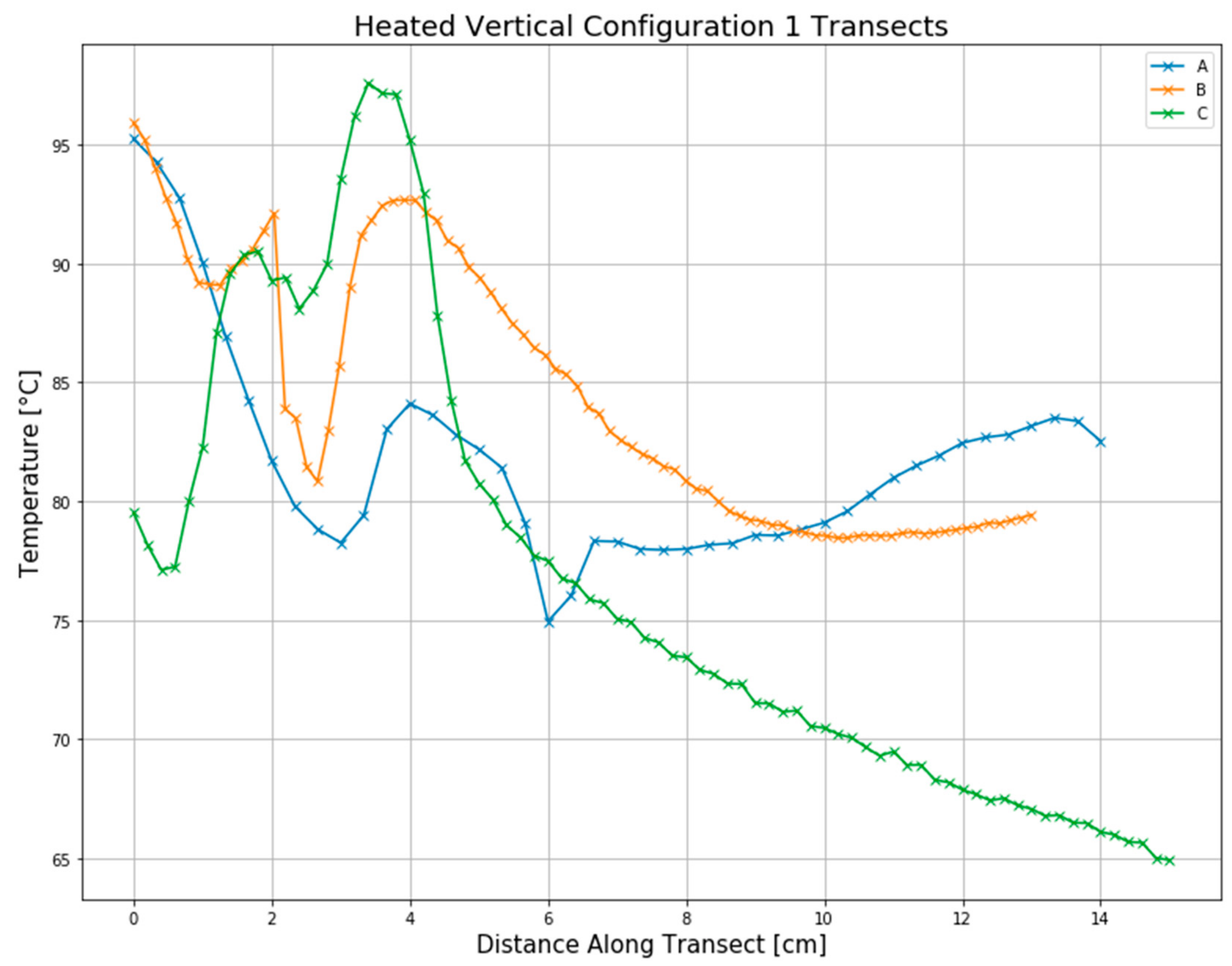
A thermal infrared temperature image captured for the heated room test, configuration 1, at the final time value (PCB in vertical orientation) is shown in Figure 9. Of note are the highly localized hotspots, again indicating poor heat transfer by the inner metal-core of the double-sided MCPCB. A plot of temperatures across the transects for this test is shown in Figure 10.
In all the tests explored by this research, the double-sided MCPCB was not effective at moving the heat away from the LED heat sources to the cooler parts of the PCB. As such, with only a minor rise in room temperature the junction-temperatures of the LED’s were driven to near maximum such that they began to under-go thermal failure. Given these results, unless some method is developed by which to couple the inner metal-core of the double-sided MCPCB to an external heat-sink, the use of this new topology is not recommend for highly localized applications such as LED light boards for machine-vision applications.
4. Summary
For a LED light board utilizing a double-sided metal-core printed-circuit-board, MCPCB, that would be constrained to only operate at or below standard room-temperature, 20 °C, the results of the experimental tests show that the maximum temperature of 65.3 °C was reached when all three LED groups were on, reaching steady-state after 12 min and would therefore provide an acceptable level of performance as this maximum was well below the maximum operating junction-temperature of the LEDs. However, for deployments, such as the intended target environment into industrial environments where the room temperatures are likely to approach or exceed 40 °C, the experimental tests in heated room yielded a maximum temperature in a horizontal orientation of 96.4 °C. The maximum temperature of the vertical orientation for the heated test was only slightly lower at 85.2 °C. As the measured hottest spot on the PCB is lower than the LED junction temperature, these elevated temperatures are likely unsafe from a component life perspective. Further evidence of unsuitability was provided by subsequent tests, in the heated room, where results were already showing thermal degradation of the components.
In examining the heat distribution via thermal transects taken using thermal infrared imaging, the double-sided MCPCB was found to perform poorly with regards to thermal dissipation of the heat generated at the LED, leading to large non-uniformity in temperatures and elevated temperatures in near locales of the heat generating LED’s. In summary, the double-sided MCPCB’s were not as effective at thermal management as the well-proven single-layer metal-backed PCB stack. Although the temperatures present in the room temperature tests were well below failure temperatures, the temperatures achieved with only modest room temperature elevation of 20 °C resulted in component failure. As such, it is recommended that most applications avoid the use of the double-sided MCPCB and, instead, strive to modify design requirements such that a single-layer metal-backed PCB option would suffice. Should that not be possible and a double-sided MCPCB be a requirement and the design be targeted to an elevated industrial environment, it is hypothesized that the elevated PCB thermal loading, leading to failure, might be mitigated if it were possible to attach a heat sink to the highly conductive metal core. One potential method by which this could be achieved would be through the addition of numerous electrical layer transition vias to help pipe the heat from the core out to the external heat sink. This is however an unproven recipe and would need to be confirmed via further experimentation and is left for future work. Another option is to simply provide a large etched area in the PCB design so that heat-sinks can be applied to key-locations to help improve heat dissipation. Due to the highly localized nature of the heating, placement would likely be critically important, and it should be noted, it would take up valuable PCB area. However, for these very specialized designs, these guide-lines may provide a means to achieve sufficient thermal performance.
Another option for consideration, to pipe heat out from the inner metal-core of the double-sided MCPCB, would be to terminate the top and or bottom layers to allow the metal core layer to be extended past the sides of the outer layers, thereby exposing the inner metal-core to the air. It would also allow for application of heat-sinks to these extended, now exposed, metal-core surfaces. However, as noted in the heat transects (Figure 5, Figure 8 and Figure 10), this would likely be of limited effectiveness due to the high localization of the heat within the covered sections of the double-sided MCPCB. It is hypothesized that the localization is potentially due to the insulative nature of the FR4 layers enclosing the metal core and is likely trapping the heat limiting the movement along the core. Thermal modeling will be explored in future work to ascertain this theory and help to develop more successful solutions. It is suggested that the most likely best recipe for two-sided MCPCB’s would be to utilize a high-density array of through-vias in near-proximity to the heat-sourcing LED’s or complete removal of outer layer via etching and then attach a heat-sink to the opposite side to help dissipate the heat in near proximity to the source. This approach however needs to be proven out first and again is left for future research. In the meantime, for a fan-less system design required to run in an elevated temperature environment, it is suggested to strive to utilize single-layer MCPCB and, until proven otherwise, avoid use of dual-sided MCPCB designs in these high thermally loaded PCB configurations.
Author Contributions
Conceptualization: M.G.P.; methodology: M.G.P., S.C.P., J.A.C., K.D.T.; experimental design and testing: M.G.P., S.C.P., K.D.T., J.A.C.; analysis: M.G.P, S.C.P., K.D.T., J.A.C.; project administration, J.D.W. and G.A.H.
Funding
This research received no external funding.
Conflicts of Interest
Mention of a product or trade-name in this article does not constitute an endorsement by the USDA-ARS over other compatible products. Products or trade names are listed for reference only. USDA is an equal opportunity provider and employer.
References
- Martin, D. A practical guide to machine vision lighting. Retrieved 2007, 11, 2013. [Google Scholar]
- Narendran, N.; Gu, Y. Life of led-based white light sources. J. Disp. Technol. 2005, 1, 167. [Google Scholar] [CrossRef]
- Todorov, D.G.; Kapisazov, L.G. Led thermal management. Electronics 2008, 2008, 139–144. [Google Scholar]
- Lasance, C.J.M.; Poppe, A. Thermal Management for LED Applications; Springer-Verlag: New York, NY, USA, 2014. [Google Scholar]
- Yung, W.K.C. Using metal core printed circuit board (MCPCB) as a solution for thermal management. J. HKPCA 2007, 24, Q2. [Google Scholar]
- Van Driel, W.D.; Fan, X.J. Solid State Lighting Reliability: Components to Systems; Springer-Verlag, Science & Business Media: New York, NY, USA, 2012; Volume 1. [Google Scholar]
- Yung, K.C.; Liem, H.; Choy, H.S. Heat transfer analysis of a high-brightness LED array on PCB under different placement configurations. Int. Commun. Heat Mass Transf. 2014, 53, 79–86. [Google Scholar] [CrossRef]
- Ngo, I.L.; Jang, H.; Byon, C.; Lee, B.J. Experimental study on thermal performance of SMD-LED chips under the effects of electric wire pattern and LED arrangement. Int. J. Heat Mass Transf. 2018, 127, 746–757. [Google Scholar] [CrossRef]
- Zhou, J.; Huang, J.; Wang, Y.; Zhou, Z. Thermal distribution of multiple led module. Appl. Therm. Eng. 2016, 93, 122–130. [Google Scholar] [CrossRef]
- Jang, H.; Lee, J.H.; Byon, C.; Lee, J. Innovative analytic and experimental methods for thermal management of SMD-Type LED chips. Int. J. Heat Mass Transf. 2018, 124, 36–45. [Google Scholar] [CrossRef]
- Tang, Y.; Ding, X.; Yu, B.; Li, Z.; Liu, B. A high power led device with chips directly mounted on heat pipes. Appl. Therm. Eng. 2014, 66, 632–639. [Google Scholar] [CrossRef]
- Hsieh, J.-C.; Lin, D.T.W.; Cheng, C.-H.; Kingkaew, S.; Chen, S.-C. The optimal design of the thermal spreading on high power LEDs. Microelectron. J. 2014, 45, 904–909. [Google Scholar] [CrossRef]
- Sufian, S.F.; Fairuz, Z.M.; Zubair, M.; Abdullah, M.Z.; Mohamed, J.J. Thermal analysis of dual piezoelectric fans for cooling multi-led packages. Microelectron. Reliab. 2014, 54, 1534–1543. [Google Scholar] [CrossRef]
- Yung, K.C.; Liem, H.; Choy, H.S.; Lun, W.K. Thermal performance of high brightness led array package on PCB. Int. Commun. Heat Mass Transf. 2010, 37, 1266–1272. [Google Scholar] [CrossRef]
- Ong, Z.Y.; Subramani, S.; Devarajan, M. Thermal simulation analysis of high power led system using two-resistor compact LED model. In Proceedings of the Fifth Asia Symposium on Quality Electronic Design (ASQED 2013), Penang, Malaysia, 26–28 August 2013; pp. 334–338. [Google Scholar]
- Lee, C.Y.; Liu, J.L. Illumination based on high-power white light-emitting diode array. Int. J. Green Energy 2012, 9, 421–429. [Google Scholar] [CrossRef]
- Park, S.-J.; Jang, D.; Yook, S.-J.; Lee, K.-S. Optimization of a chimney design for cooling efficiency of a radial heat sink in a LED downlight. Energy Convers. Manag. 2016, 114, 180–187. [Google Scholar] [CrossRef]
- Shen, Q.; Sun, D.; Xu, Y.; Jin, T.; Zhao, X. Orientation effects on natural convection heat dissipation of rectangular fin heat sinks mounted on LEDs. Int. J. Heat Mass Transf. 2014, 75, 462–469. [Google Scholar] [CrossRef]
Figure 1.
(a) Typical single-sided metal-core printed circuit board, MCPCB, Stack-Up design (b) Double-Sided MCPCB Stack-Up design.
Figure 1.
(a) Typical single-sided metal-core printed circuit board, MCPCB, Stack-Up design (b) Double-Sided MCPCB Stack-Up design.

Figure 2.
(a) LED group position layout configuration (b) and associated printed-circuit-board, PCB, design schematic utilized in the thermal dissipation experiments.
Figure 2.
(a) LED group position layout configuration (b) and associated printed-circuit-board, PCB, design schematic utilized in the thermal dissipation experiments.

Figure 3.
Temperature vs. time plots of LED configurations for room temperature tests.

Figure 4.
Thermal infrared temperature image of configuration 5 at time, t = 11 min.

Figure 5.
Infrared temperature transects, from Figure 4, for 20 °C room temperature test, configuration 5, snapshot shown at time, t = 11 min.
Figure 5.
Infrared temperature transects, from Figure 4, for 20 °C room temperature test, configuration 5, snapshot shown at time, t = 11 min.

Figure 6.
Figure details the hottest location on the printed-circuit-board’s temperature vs. time for the room heated tests, for configuration 1, in both horizontal and vertical orientations of the circuit-board.
Figure 6.
Figure details the hottest location on the printed-circuit-board’s temperature vs. time for the room heated tests, for configuration 1, in both horizontal and vertical orientations of the circuit-board.

Figure 7.
Thermal infrared temperature image of the heated room test, configuration 1, at time t = 21 min, with the circuit-board oriented horizontally.
Figure 7.
Thermal infrared temperature image of the heated room test, configuration 1, at time t = 21 min, with the circuit-board oriented horizontally.

Figure 8.
Temperatures across the thermal infrared image transects of Figure 7, for the heated-room, configuration 1 test with circuit-board in horizontal orientation, at time t = 21 min.
Figure 8.
Temperatures across the thermal infrared image transects of Figure 7, for the heated-room, configuration 1 test with circuit-board in horizontal orientation, at time t = 21 min.

Figure 9.
Thermal infrared temperature image of heated-room test, configuration 1, for circuit-board in vertical orientation, at time t = 19 min.
Figure 9.
Thermal infrared temperature image of heated-room test, configuration 1, for circuit-board in vertical orientation, at time t = 19 min.

Figure 10.
Temperatures across the thermal-infrared image transects, for heated-room test, configuration 1, for circuit-board in vertical orientation, at time t = 19 min.
Figure 10.
Temperatures across the thermal-infrared image transects, for heated-room test, configuration 1, for circuit-board in vertical orientation, at time t = 19 min.


Table 1.
Materials list for the LED design utilized in the thermal dissipation experiments.
| Name | Quantity | Manufacturer | Model |
|---|---|---|---|
| Thru-Hole LED Drivers | 3 | Mean Well USA Inc. | 709-LDD-700L |
| Surface mount LEDs | 18 | Lumileds | L1V2-6570000000000 |
| Solder Paste | 1 | Chip Quik | FBA_5880 |
| PCB Stencil | 1 | PCBWay | |
| MCPCB | 1 | PCBWay | |
| Thermal Imaging Camera | 1 | FLIR | i7 |
| Thermometer | 1 | OMEGA | HH506RA |
| Low Noise Power Supply (set to 18V) | 1 | Potrans | FS-32024-1M |
| 26 Qt Cooler | 1 | Igloo | 00040358 |
Table 2.
Board Schematic and EAGLE design files utilized in the thermal dissipation experiments.
| Name | Description |
|---|---|
| Light_Board_Small_V2.sch | EAGLE schematic file |
| Light_Board_Small_V2.brd | EAGLE board file |
Table 3.
Light-emitting-diode, LED, configurations utilized in the thermal dissipation experiments.
| Configuration Number | Description |
|---|---|
| 1 *,† | Top Left, top right, and bottom left LED groups on |
| 2 * | Top left and top right LED groups on, bottom left LED group off |
| 3 * | Top left and bottom left LED groups on, top right LED group off |
| 4 * | Top right and bottom left LED groups on, top left LED group off |
| 5 * | Top left LED group on, top right and bottom left LED groups off |
| 6 * | Top right LED group on, top left and bottom left LED groups off |
| 7 * | Bottom left LED group on, top left and top right LED groups off |
* Indicates the configuration was used in the room temperature tests. † Indicates the configuration was used in the heated room tests.
© 2019 by the authors. Licensee MDPI, Basel, Switzerland. This article is an open access article distributed under the terms and conditions of the Creative Commons Attribution (CC BY) license (http://creativecommons.org/licenses/by/4.0/).
Share and Cite
MDPI and ACS Style
Pelletier, M.G.; Preston, S.C.; Cook, J.A.; Tran, K.D.; Wanjura, J.D.; Holt, G.A. Thermal Performance of Double-Sided Metal Core PCBs. AgriEngineering 2019, 1, 539-549. https://0-doi-org.brum.beds.ac.uk/10.3390/agriengineering1040039
AMA Style
Pelletier MG, Preston SC, Cook JA, Tran KD, Wanjura JD, Holt GA. Thermal Performance of Double-Sided Metal Core PCBs. AgriEngineering. 2019; 1(4):539-549. https://0-doi-org.brum.beds.ac.uk/10.3390/agriengineering1040039
Chicago/Turabian StylePelletier, Mathew G., Stone C. Preston, Jim A. Cook, Kevin D. Tran, John D. Wanjura, and Greg A. Holt. 2019. "Thermal Performance of Double-Sided Metal Core PCBs" AgriEngineering 1, no. 4: 539-549. https://0-doi-org.brum.beds.ac.uk/10.3390/agriengineering1040039