1. Introduction
Modern precision agriculture is a complex process, at each stage of which it is necessary to make management decisions. The quality of the decisions taken is determined by the completeness and reliability of the available information on the condition of agricultural plants, soil composition and fertility, moisture content, and its availability to the root system, as well as a number of other indicators [
1,
2,
3,
4]. Currently, methods of remote radar measurement of the soil’s physical and chemical parameters are being actively introduced using aircraft and spacecraft [
5,
6]. Such systems have advantages of quickness and covering large areas, but they fall significantly behind laboratory methods in terms of measurement accuracy. At the same time, laboratory studies of soil samples taken within the same soil area, as well as the use of stationary sensors, do not provide the required speed, and the results obtained do not allow for an assessment of soil conditions over vast territories [
7,
8,
9].
With the emergence of unmanned aerial vehicles (UAVs), studies [
10,
11,
12,
13,
14,
15] are being conducted to determine the physicochemical parameters of soil using oblique irradiation of the Earth’s surface in order to create conditions for the occurrence of the total (pseudo-total) refraction effect [
6,
16]. The advantage of this approach is that it allows for estimating the soil parameters directly in the root zone of plants. The oblique angle of incidence of an electromagnetic wave (Brewster angle), at which the effect of total (pseudo-total) refraction is observed, depends on the complex dielectric permittivity of the media that form the air–surface interface [
17]. Therefore, with a known value of the Brewster angle, it is possible to determine the electrical parameters of dielectric media and estimate the moisture content, granulometric composition, and specific conductivity of soil horizons on the basis of these parameters using the known pedotransfer functions [
18].
Among the methods for determining the electrical properties of dielectrics using the Brewster effect to some extent, the articles cited in [
19,
20,
21,
22,
23,
24,
25] can be highlighted. The mathematical framework of these methods is based on Snell’s laws and Fresnel’s formulas for a flat interface between two lossless dielectrics under the condition of specular reflection of the probing signal of the radio or optical range [
9,
26,
27]. In our opinion, the influence of various factors on the accuracy of determining the Brewster angle has not been sufficiently investigated in these methods when applied to the real, naturally occurring planar-layered dielectrics [
28]. Taking into account the emergence of new technical means for oblique irradiation of the Earth’s surface (e.g., UAVs) and the active integration of remote-sensing methods for measuring the physical and chemical parameters of soil into precision farming technology, the assessment of the accuracy characteristics of methods for determining the Brewster angle becomes even more relevant.
Thus, the aim of the study is to analyze the mathematical expressions that describe the process of the formation of an interference radar signal during oblique irradiation of a plane-layered dielectric, which makes it possible to evaluate the accuracy of measuring the Brewster angle. Based on the results of the modeling, it is possible to formulate recommendations for implementing approaches that can reduce measurement errors in real-world conditions.
A contradiction arises between the active use of remote-sensing methods for measuring the physico-chemical parameters of soil, including the use of the Brewster effect, and the lack of a scientific and methodological apparatus that sufficiently allows for the evaluation of the influences of different factors on the accuracy of determining the Brewster angle and other parameters based on it.
To achieve the set goal, it is necessary:
To develop a mathematical model of electromagnetic wave interference;
To carry out an experimental verification of the adequacy of the developed model;
To conduct a study of the mathematical model to identify the factors influencing the accuracy of determining the Brewster angle;
To develop recommendations for the use of the known amplitude and proposed phase methods for measuring the Brewster angle under various conditions;
To demonstrate how, by measuring the Brewster angle, we can estimate the physical and chemical parameters of the soil using the example of determining its volumetric moisture content.
The solution to the first two problems is presented in the Research Methodology section. The Results section is dedicated to the study of the mathematical model of interference and the evaluation of its accuracy. The recommendations for using the known amplitude and newly proposed phase measurement methods for estimating the physical and chemical parameters of soil are given in the Discussion section.
2. Research Methodology
To estimate the accuracy of the Brewster angle measurement, it is proposed to use a model of electromagnetic (EM) wave interference in a three-layer propagation medium with two boundary transitions. When analyzing the physicochemical parameters of agricultural soils, these may be: the layer of air, close to vacuum in properties; the upper fertile layer of soil, represented by a dielectric with losses (due to humidity, for example); the layer of soil in which groundwater is located and which is close in its properties to conductors. In this model, the interference wave is formed by the addition of waves: a direct wave propagating only in air, a wave reflected from the air–surface interface and the sum of partial waves that have passed through the air–surface interface and are reflected from the soil layer with groundwater. To denote the corresponding electromagnetic waves, we will use the following names: direct, reflected and soil waves.
The mathematical description of complex amplitude of a direct wave follows from the solution of the Helmholtz wave equation for a wave whose phase increases with the distance from the radiation source [
29] (p. 299):
where
is the wave amplitude depending on the distance
traveled by the EM wave (in this case, the distance between the transmitting and receiving antennas) without regard to attenuation in the medium;
is the propagation coefficient of the wave;
is the wavelength.
The complex amplitude of reflected waves is formed on the basis of the direct wave, considering the change in the amplitude and phase at the point of reflection in proportion to the reflection coefficient. Reflection of EM waves at the interface between two dielectric media differs for the vertically and horizontally polarized waves:
where
is the wave amplitude depending on the distance
traveled by the reflected wave without regard to attenuation;
,
are the complex reflection coefficients for the vertically and horizontally polarized waves, which are determined by the known Fresnel formulas [
29] (p. 306).
The set of soil waves is determined by the condition that each partial wave must enter the aperture area of the receiving antenna after undergoing the refraction at the “air-dielectric” interface, the reflection from the groundwater horizon (or sea water) and the reverse refraction into the air medium:
where
,
are the complex refractive indices of the vertically and horizontally polarized signals for the angle of incidence
and the angle of refraction
at the interface between the first and second media;
,
are the complex reflection coefficients of the vertically and horizontally polarized signals from the soil layer boundary at the groundwater level;
,
are the complex refractive indices of the vertically and horizontally polarized signals when passing from a denser medium (the first soil layer) into air;
is the propagation coefficient in the first soil layer, which, in the general case, is complex and consists of the phase coefficient (wave number) and attenuation coefficient;
is the distance traveled by the electromagnetic wave in the second medium;
d is the thickness of the first soil layer.
Thus, interference waves with the vertical and horizontal polarization at the receiving point are represented by the expressions, respectively:
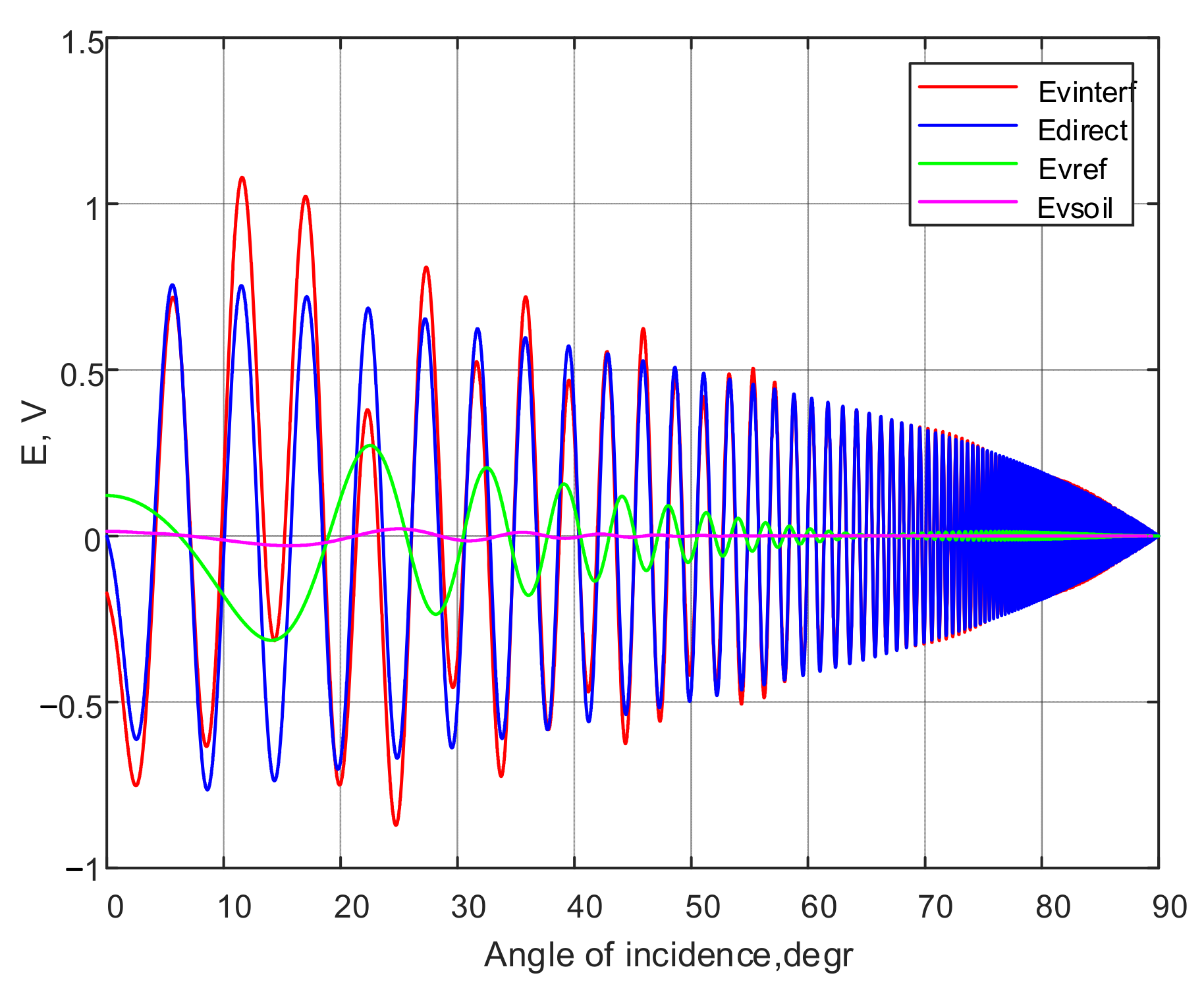
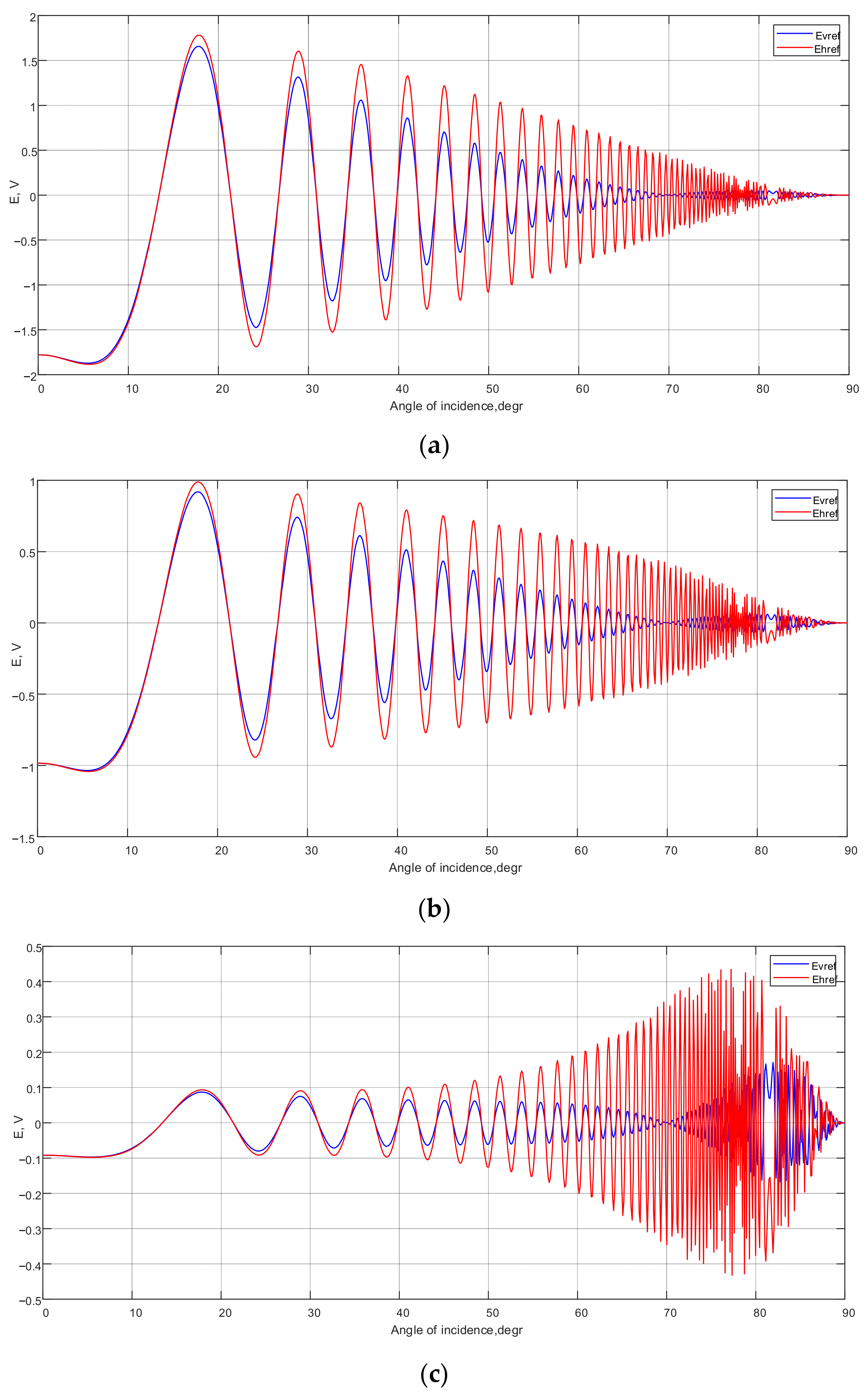
The results of mathematical modeling in Matlab using expressions (1)–(7) are shown in
Figure 1 and
Figure 2 as graphs of the moduli of the complex amplitudes included in the expressions (6) and (7).
The input data used for modeling correspond to the typical conditions of remote-sensing techniques used to determine the physical and chemical parameters of agricultural soils. The initial data used in the modeling include:
Frequency of the probing signal f = 469.0 MHz;
Thickness of the dielectric layer to be investigated d = 2 m;
Relative dielectric permittivity of the first medium (air) = 1;
Specific conductivity of the first medium (air) σ1= 0 S/m;
Relative permittivity of the second medium (wet loamy soil) = 3.5;
Specific conductivity of the second medium σ2 = 0.015 S/m;
Relative dielectric permittivity of the third medium (watered clay layer) = 30;
Specific conductivity of the third medium σ3 = 0.15 S/m.
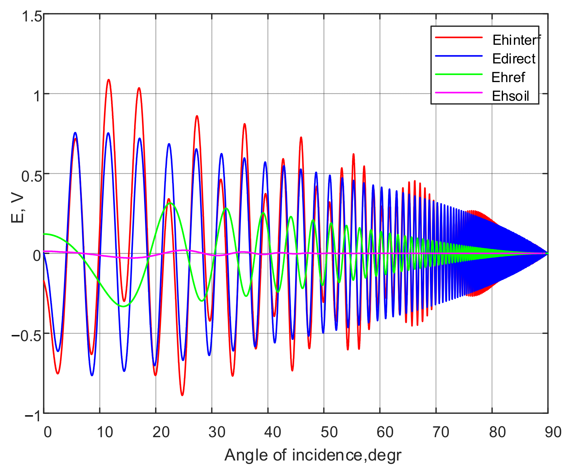
As follows from the obtained modeling results (see
Figure 1 and
Figure 2), the interference waves have an oscillatory nature associated with the phase difference between the direct, reflected and soil waves at the observation point. The amplitude of the horizontally polarized interference wave decreases in proportion to the increase in the distance between the transmitting and receiving positions required to create different angles of incidence of the probing signal in the range from 0 to 90 degrees. The changes in the amplitude of a vertically polarized interference wave (
Figure 1) are more informative; they occur under the influence of two factors. The amplitude decreases due to an increase in the distance between the transmitting and receiving positions and changes proportionally to the reflection coefficient. The second factor leads to the emergence of a minimum corresponding to the Brewster effect. The presence of the minimum of the interference wave amplitude, the proximity of the minimum to zero and its location on the abscissa axis are determined by the dielectric permittivity and the specific conductivity of the top soil layer.
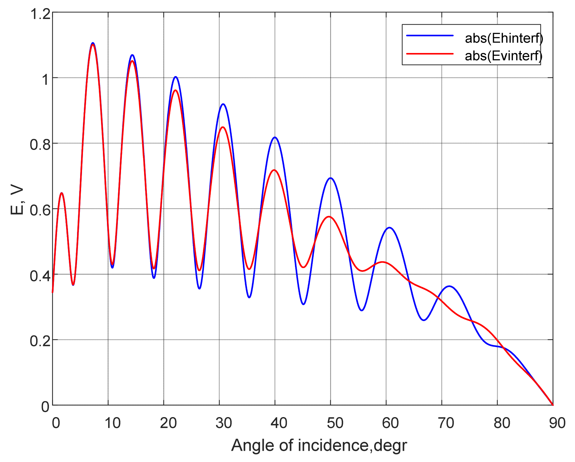
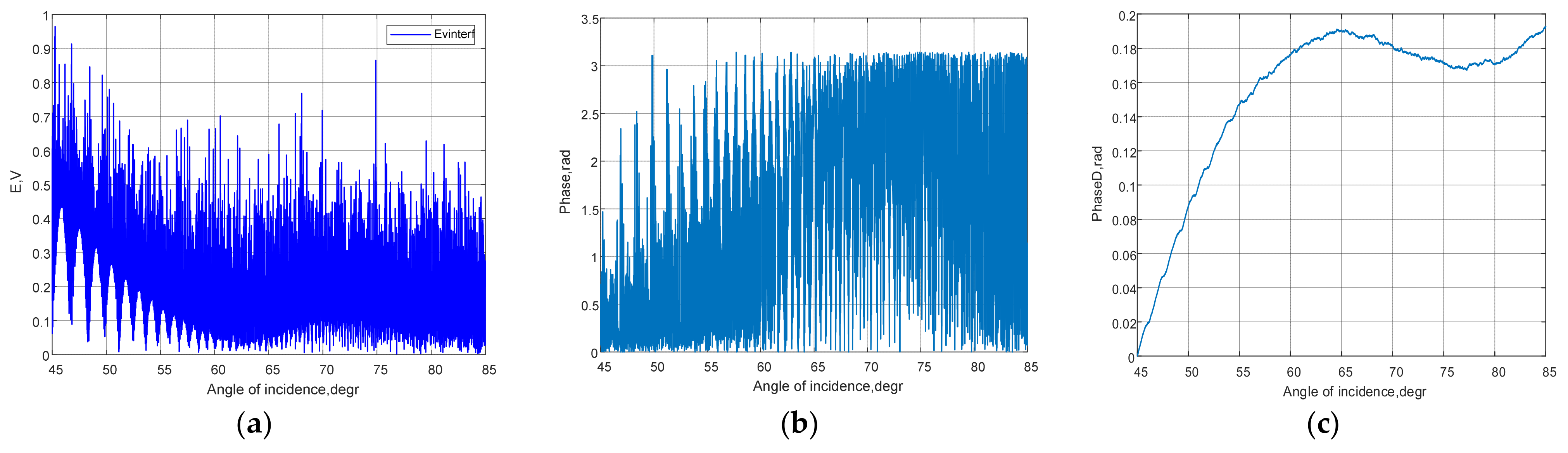
Figure 3 displays graphs depicting the moduli of the complex amplitudes of the vertically and horizontally polarized interference waves.
As shown in
Figure 3, when the angle of incidence is equal to the Brewster angle, a phase shift appears between the oscillations of the vertically and horizontally polarized interference waves. This, along with the minimum amplitude, is a sign of the Brewster effect.
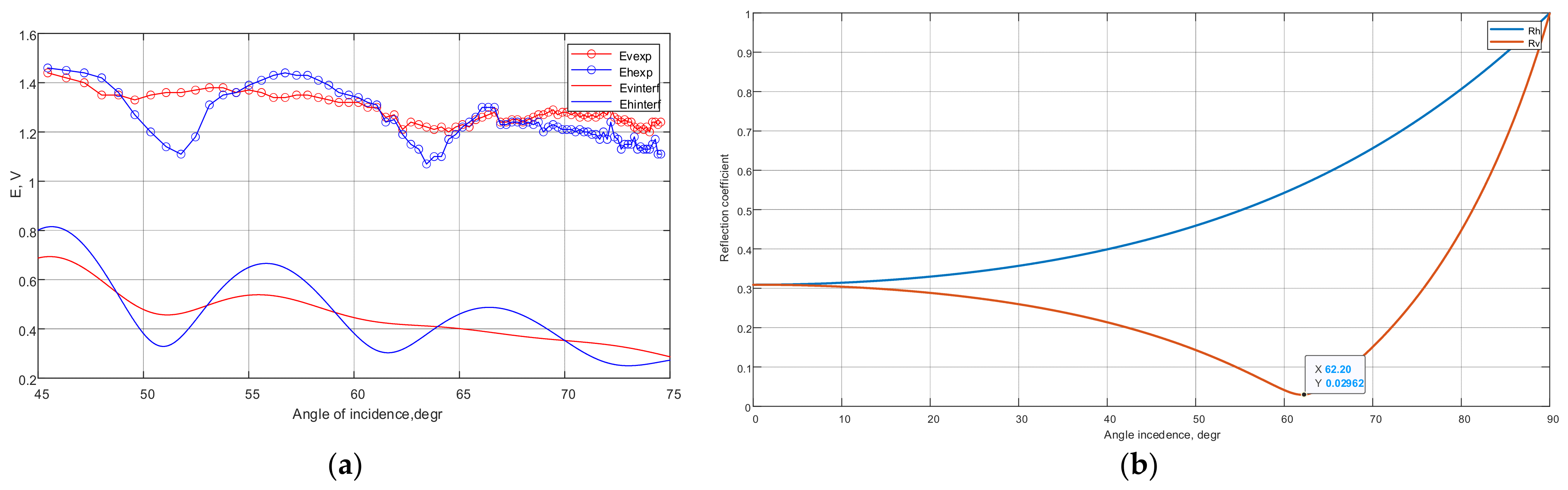
Figure 4a shows the joint graphs of the results of mathematical modeling and experimental studies in the range of incidence angles from 45 to 75 degrees, where the Brewster effect is observed to occur in real soils. The exact value of Brewster’s angle is 62.20 degrees (see
Figure 4b).
The results of measuring the amplitudes of interference waves with vertical and horizontal polarization at different angles of incidence of the probing signal are presented in
Table 1. The experimental conditions correspond to the modeling conditions. Additionally, the following conditions were defined:
The transmitting antenna mounting height is 3.2 m;
The receiving antenna mounting height is 3.0 m;
Microstrip antennas with two types of polarization of the received (transmitted) signal.
The radio transmitter of the portable radio station TK-450S was used to form the probing signal. A portable Anritsu S362E antenna-feeder analyzer was used as a receiver.
The difference between the measured and simulated amplitudes of interference signals is determined by the presence of an electromagnetic background equal, on average, to 0.7 V at the experiment location. When comparing the experimental and modeled data, the locations of oscillation maxima and minima, as well as the intersection points of the oscillation graphs depicting the moduli of the vertically and horizontally polarized interference waves, do not differ by more than 10 percent. The experimentally measured Brewster angle is 62.60 degrees, and the magnitude obtained from the simulation results is 62.20 degrees. Thus, the good convergence between the results of modeling and experimental data allows for the use of the proposed mathematical model to study the Brewster angle measurement error.
3. Results
A comparative assessment of the accuracy characteristics was conducted for the four methods of measuring the Brewster angle: by the minimum of the modulus of the vertically polarized interference wave; by the equality to zero of the derivative of the dependence of the modulus of the vertically polarized interference wave on the angle of incidence; by the phase shift between the vertically and horizontally polarized interference waves; by the phase shift between the vertically and horizontally polarized interference waves with normalized amplitudes. The normalization is performed in order to exclude the influence of amplitude and consists of replacing all positive values of amplitude with 1 and negative values with −1.
Figure 5,
Figure 6 and
Figure 7 show graphs reflecting the initial conditions for measuring the Brewster angle
(relative permittivity
, specific conductivity of the topsoil
) without the influence of external perturbing factors. The calculated value for the Brewster angle is 62.20 ± 0.32 degrees. The scattering of values of 0.64 degrees confirms the fact that for lossy dielectrics, the pseudo-Brewster effect occurs when the reflection coefficient does not reach zero, but only decreases to a certain minimum (when modeling
, see
Figure 4b).
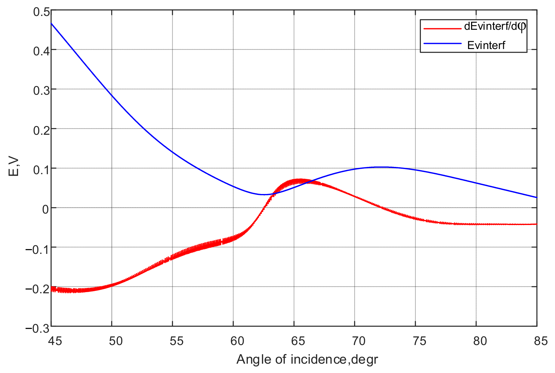
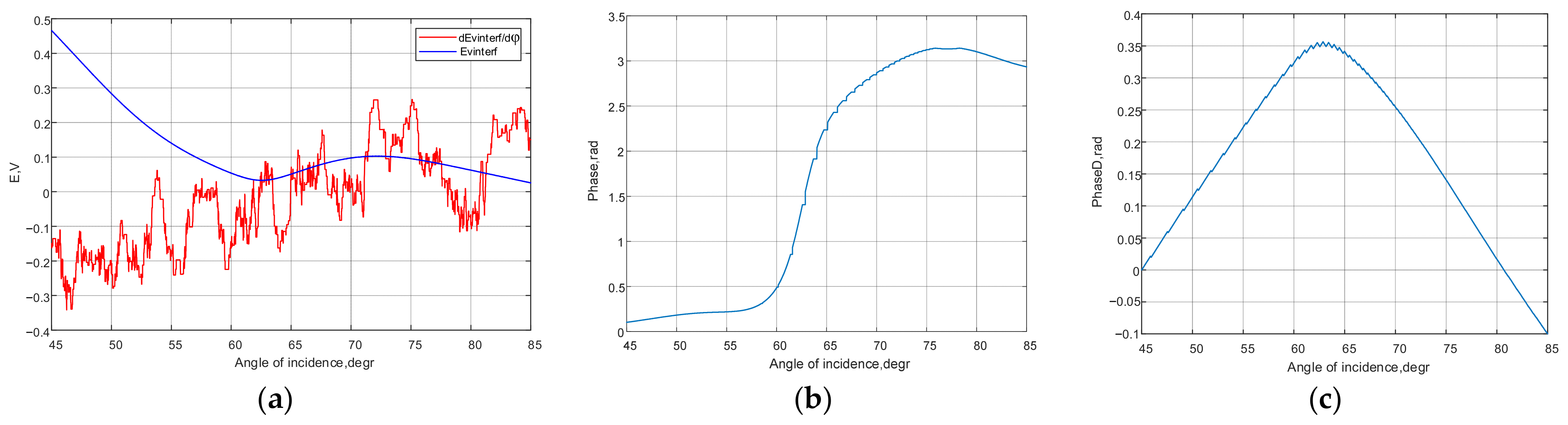
In
Figure 5, graphs of the vertically polarized interference wave and its derivative are presented. The amplitude of the vertically polarized interference wave has a plane segment of 29 identical values equal to the minimum of 0.0328 V, which corresponds to the calculated values of the model in the range of incident angles from 62.40 to 62.51 degrees, i.e.,
. The absolute error was 0.26 degrees.
The derivative of the function is zero at the first extremum, i.e., when the angle of incidence is equal to the Brewster angle. Through the derivative modeling, we obtained a Brewster angle of 62.54 degrees. The absolute error was 0.34 degrees, and there was no scattering of values.
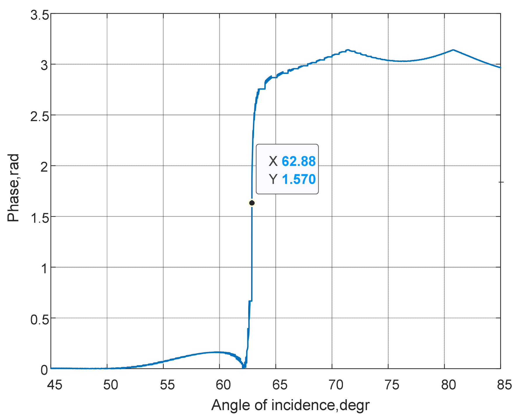
The phase changes associated with the Brewster effect are estimated by the phase difference of the complex amplitudes of interference waves with vertical and horizontal polarization (see
Figure 3). When the wave is reflected from the soil surface, the phase of the complex amplitude of the reflected wave changes by 180 degrees. This manifests itself in the phase of the vertically polarized interference wave. The phase difference between the vertically and horizontally polarized interference waves equal to
indicates the presence of the Brewster effect.
Figure 6 shows the results of calculating the phase difference of the interference waves. The phase shift value of 1.57 rad corresponds to the angle of 62.88 degrees. Thus, the absolute measurement error is 0.68 degrees.
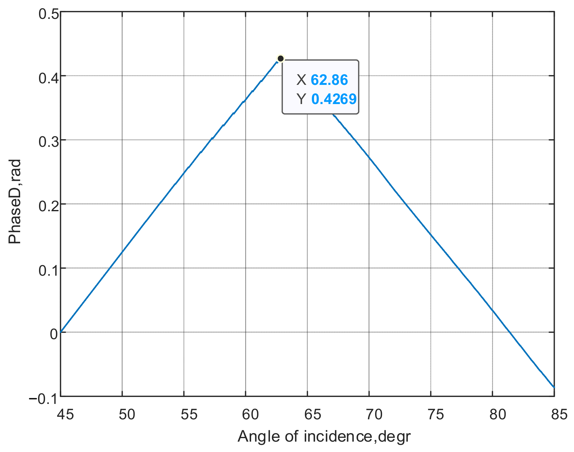
The normalized interference signals are processed using a digital phase discriminator. The algorithm of the digital phase discriminator works on the principle of accumulation of phase differences of the normalized amplitudes of the vertically and horizontally polarized interference waves. When the amplitudes coincide (both amplitudes are equal to 1, or both are equal to −1), the discriminator performs subtraction. In the case of a mismatch (−1 and 1 or vice versa), the discriminator performs summation. The maximum of the discriminative characteristic corresponds to the Brewster angle.
Figure 7 shows the discriminative characteristic, the maximum of which is equal to 0.4269 rad and corresponds to the Brewster angle of 62.86 degrees. The absolute error is 0.66 degrees.
Thus, when measuring the Brewster angle without accounting for random noise (without perturbing factors), the absolute measurement error ranges from 0.26 to 0.68 degrees. The method based on determining the minimum of the complex amplitude modulus of the vertically polarized interference wave ensures the formation of a range of values satisfying the condition for a local minimum. The calculation of the derivative of the complex amplitude modulus of the vertically polarized interference wave and the determination of the moment when it transitions through the zero value (extremum) yield only one value with an absolute error of less than 0.50 degrees. Phase methods are found to be less accurate, but in both cases, the Brewster angle measurement error is less than 0.68 degrees.
To evaluate the precision of measuring the Brewster angle, it is proposed to analyze the perturbing factors that the authors consider as the most important ones:
The ratio of the amplitudes and phase shifts of the direct, reflected and soil waves;
The sizes of irregularities and their statistical characteristics at the point of incidence, as well as their influence on the type of reflection (diffuse, specular or mixed);
The presence and magnitude of permissible random changes in the amplitude and phase (noise) separately for the direct, reflected and soil waves and the integral noise of the interference wave.
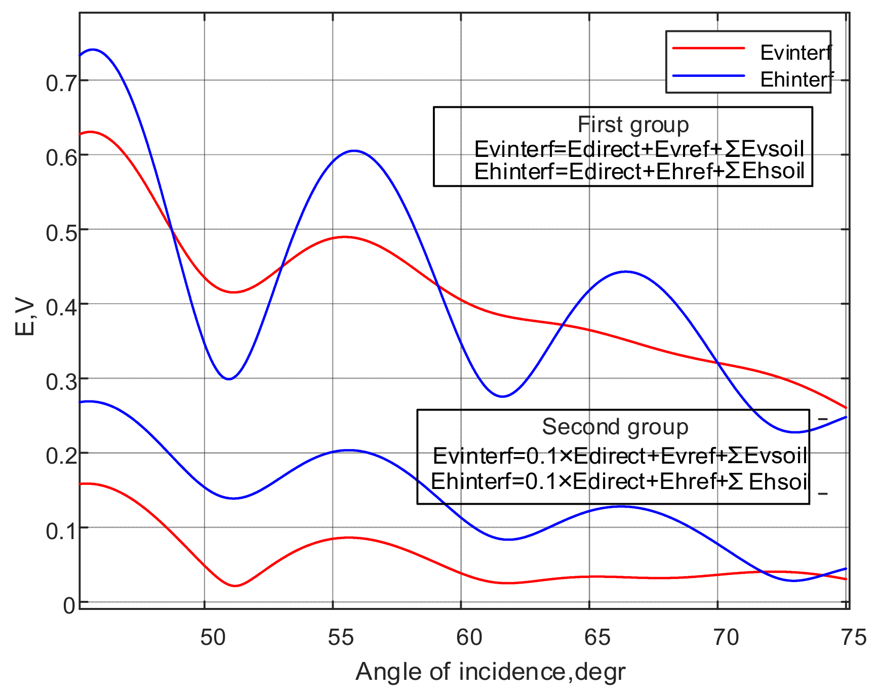
Figure 8 shows graphs of the vertically and horizontally polarized interference waves for the case when the wave amplitudes are determined by the expressions (6) and (7) (the first group of graphs) and the case when the amplitude of the direct wave is reduced tenfold (the second group of graphs).
As can be seen from
Figure 8, forced decreasing of the amplitude of the direct wave (e.g., by creating a specific antenna pattern) results in a decrease in the energy of interference waves and the emergence of additional minima of the amplitude modulus of the vertically polarized interference wave.
The irradiation of the Earth’s surface is intended to be carried out in accordance with the Rayleigh criterion [
29]:
The size of irregularities and their statistical characteristics at the point of incidence are taken into account by multiplying the reflection coefficient by the roughness coefficient:
where
is the height of random irregularities;
is the root mean square deviation of the height of random irregularities.
Figure 9a–c presents graphs that illustrate the influence of the sizes of irregularities of the investigated surface on the type of the reflected signal. According to
Figure 9, when the size of the irregularity increases, the amplitude of the reflected signal decreases in the region of small angles of incidence. Outside the Brewster angle, the level of the reflected signal becomes higher. The size of the irregularities has a particularly significant impact on the amplitude of the horizontally polarized reflected signal. When
, the characteristics of the reflected signal do not allow for determining the Brewster angle.
A set of random factors causing the distortion of amplitudes and phases of the direct, reflected and ground waves is modeled by additive interference with a normal distribution and mathematical expectation equal to zero.
Figure 10a presents graphs of the vertically polarized interference wave and its derivative during the modeling of noises caused by the direct, reflected and ground waves by additive interference with a root mean square deviation of 0.0001 V. It is clear that calculating the Brewster angle using the derivative of the modulus of the complex amplitude of the vertically polarized interference wave is impossible, even in the presence of such noises. The errors of the phase methods are 0.7 degrees (
Figure 10b) and 0.66 degrees (see
Figure 10c), respectively.
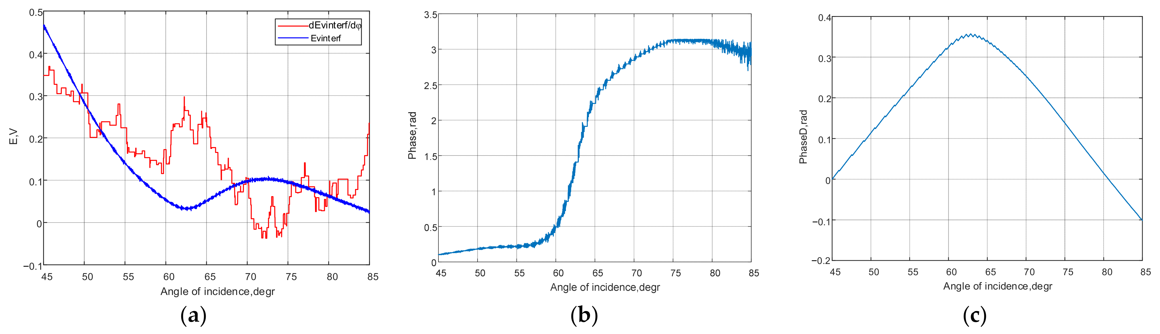
Figure 11 shows the conditions for measuring the Brewster angle when modeling the noises from the direct, reflected and ground waves by additive interference with a root mean square deviation of 0.001 V.
The graph of the modulus of the complex amplitude of the vertically polarized interference wave (
Figure 11a) has three local minima at the angles of incidence: 61.96; 62.62; 63.12 degrees. The absolute error for the first local minimum is 0.24 degrees, and the maximum error is 0.92. The phase shift of 1.57 rad is achieved at an angle of incidence of 62.91 (
Figure 11b), which corresponds to an absolute error of 0.71 degrees. The Brewster angle measured by the digital phase discriminator is 62.86 degrees (
Figure 11c), and the measurement error is 0.66 degrees.
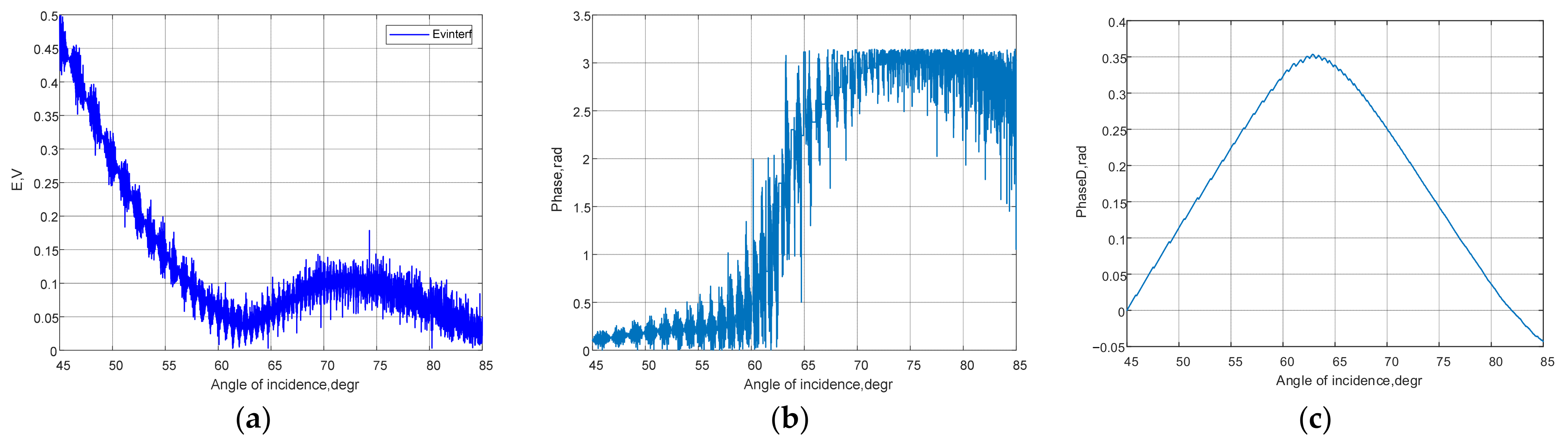
Figure 12 shows the conditions for measuring the Brewster angle when modeling the noises from the direct, reflected and soil waves by additive interference with a root mean square deviation of 0.01 V.
The graph of the modulus of the complex amplitude of the vertically polarized interference wave (
Figure 12a) has seven local minima at the angles of incidence: 60.77; 61.38; 62.03; 62.59; 63.16; 63.71; 64.21 degrees. The maximum error for the first minimum is 2.01 degrees. Several angles of incidence meet the condition that the phase shift is 1.57 rad (
Figure 12b), and the maximum measurement error is 2.66 degrees. The Brewster angle measured by the digital phase discriminator is 62.9 degrees (
Figure 12c), and the absolute error is 0.7 degrees.
Figure 13 shows the conditions for measuring the Brewster angle when modeling the noises from the direct, reflected and soil waves by additive interference with a root mean square deviation of 0.1 V.
As can be seen from
Figure 13a,b, it is not possible to measure the Brewster angle from the minimum modulus of the complex amplitude of the vertically polarized interference wave or from the phase shift of the vertically and horizontally polarized interference waves. At the same time, the digital phase discriminator remains operational (
Figure 13c). The measured value of the Brewster angle is 63.64 degrees; the absolute measurement error is 1.44 degrees.
4. Discussion
The obtained estimates of the absolute error in measuring the Brewster angle indicate that in the absence of random perturbing factors, both the amplitude and phase methods are quite accurate, with an absolute error not exceeding one degree. When studying dielectrics with losses (for example, wet, salty soils), the accuracy of measuring the Brewster angle decreases. This is due to the absence of a pronounced minimum of the vertically polarized interference signal. The increase in the size of the surface irregularities and their dispersion changes the reflection of the electromagnetic waves, making it diffuse-specular. Under certain conditions, this leads to the impossibility of determining the Brewster angle. The method in which the partial derivative of the dependence of the modulus of the complex amplitude was calculated from the angle of incidence of the electromagnetic wave turned out to be the most sensitive to the effects of additive interference.
The phase method with normalized amplitude values of the vertically and horizontally polarized interference waves proves to be the most resistant to all perturbing factors, as analyzed in the paper. When measuring the Brewster angle using this method, the error does not exceed one degree. This holds true even when dealing with diffuse-specular reflection from the upper layer of the lossy dielectric, when additive interference exceeds 10 percent of the useful signal level.
The determination of the Brewster angle
makes it possible to estimate the relative permittivity
of the topsoil using the well-known expression [
30] (p. 307):
At
, the error of 1° (
results in a nine percent increase in relative permittivity. Thus, with the error obtained from the phase method with normalized interference waves’ amplitudes of less than one degree, the error in measuring the relative permittivity does not exceed the generally accepted technical requirements [
18].
The assessment of the physicochemical parameters of soil (e.g., moisture) is carried out using pedotransfer functions that are set out in the international recommendations [
18].
Thus, relative dielectric permittivity with volumetric moisture content
, composition (percentage of soil particles
,
,
), and soil density are related by the expression:
where
is the bulk density of soil;
is the specific gravity of a dry mixture of soil constituents;
is the component of dielectric permittivity determined by soil density,
;
;
;
is the real part of complex relative permittivity of bound water.
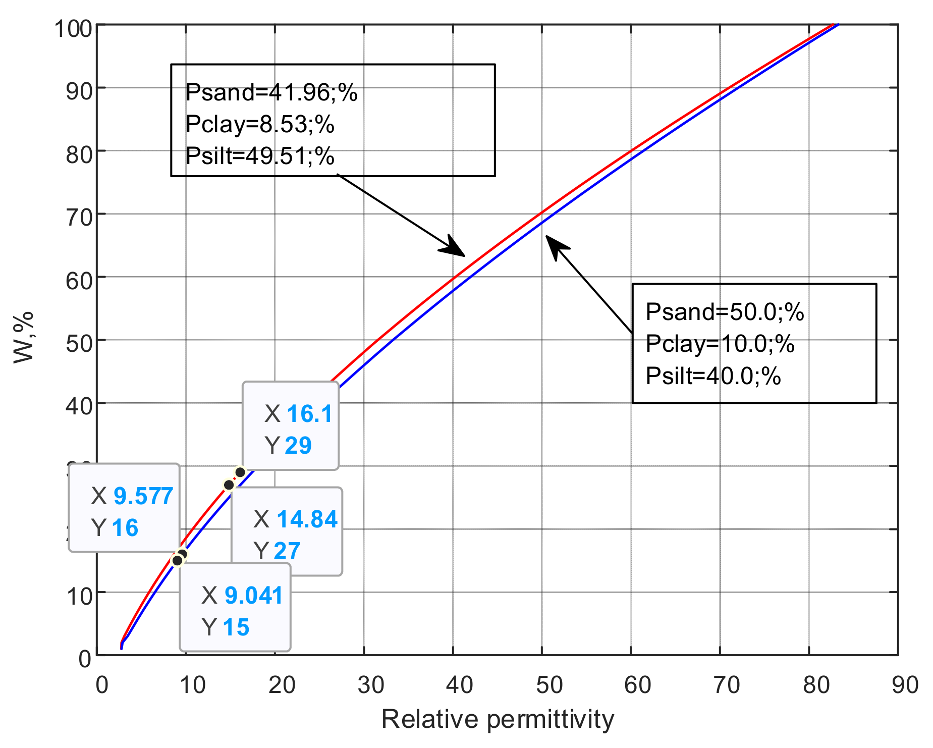
Figure 14 shows the results of calculating the relative permittivity for the different values of volumetric moisture content and for several types of soil composition. On each of the graphs, two points are randomly chosen whose relative permittivity value (
x-axis) does not differ by more than 10% (7.82% and 5.39%). The corresponding values of volumetric moisture (
y-axis) also do not exceed ten percent (6.89% and 6.25%). As such, we can conclude that measuring the Brewster angle with an error of less than one degree allows us to determine soil moisture with an error not exceeding ten percent.
5. Conclusions
Thus, based on the solution of the Helmholtz wave equation and Fresnel formulas, a mathematical model of electromagnetic wave interference at the boundary of lossy dielectric media was developed. Experimental confirmation has been obtained to validate the adequacy of the developed model using the most probable set of input data.
The model takes into account the root mean square deviations of the roughness heights at the air–surface interface, which affect the ratio of specularly and diffusely reflected rays, as well as the level of additive noise with the normal distribution law of individual complex amplitudes of the direct, reflected and ground waves.
The obtained results of mathematical modeling, theoretical and experimental research enable remote measurement of the soil’s physical and chemical parameters, such as moisture content, with an accuracy sufficient for rational crop management using precision farming technology.
Timely remote determination of soil moisture at different stages of development of agricultural plants will allow for a reasonable choice of rational agrotechnical measures. Further research will aim to evaluate the cation exchange capacity, the particle size distribution (granulometric composition) and the humus content of soil by measuring the Brewster angle and the complex dielectric constant of soil.
One of the important results achieved through the developed model is the estimation of the error in determining Brewster’s angle using various measurement methods and conditions. The findings demonstrate that information about the Brewster angle lies not only in the minimum amplitude of the vertically polarized interference signal; this information is also provided by the phase difference between the vertically and horizontally polarized interference waves. The boundary conditions determining the applicability of different methods for estimating the Brewster angle have been examined. It has been shown that the method based on the calculation of the derivative of the functional dependence of the amplitude of the vertically polarized interference signal is ineffective, even under conditions of additive noise less than 0.01% of the amplitude value. A phase method for determining the Brewster angle is proposed, based on the implementation of a digital phase discriminator algorithm for the phase difference between the vertically and horizontally polarized interference waves, normalized by amplitude. The possibility of measuring the Brewster angle with an accuracy of less than one degree using the proposed phase method has been justified. This allows for determining soil moisture with an error not exceeding ten percent.
The authors associate the prospects for further research on the accuracy of the Brewster angle measurement with the combination of amplitude and phase methods, as well as with the application of digital processing of interference signals.


 ,
, 


