
Subsoil Melioration with Organic Material—Principle, Technology and Yield Effects


Institute of Agricultural Engineering, University of Bonn, 53115 Bonn, Germany
*
Author to whom correspondence should be addressed.
Agronomy 2021, 11(10), 1970; https://0-doi-org.brum.beds.ac.uk/10.3390/agronomy11101970
Submission received: 20 August 2021
/
Revised: 27 September 2021
/
Accepted: 27 September 2021
/
Published: 29 September 2021
(This article belongs to the Special Issue Papers from AgEng2021)
Abstract
:An increasing challenge for agriculture in times of climate change is to sustainably ensure or increase the yield capacity of crop production. Low-yielding sites are particularly at risk in this respect. One strategy to counteract is to promote the use of the subsoil. This article describes the technical procedure and development of an implement for stripe-wise subsoil melioration with application of compost in a layer of 30–60 cm. These stripes are each 30 cm wide and 70 cm apart. A technology has been developed for process, which allows the described procedure to be used over a large area. The melioration is carried out in one pass by an implement in an arrangement of 3 rows resulting in a working width of 3 m. A hopper on top of the implements frame includes an embedded hydraulic system to feed compost into the injection coulter. Results from 4-year field trials with standard crop rotations verify yield increases of up to 20% still 5 years after melioration. An overview of these trials and results will also be presented.
1. Introduction
Climate change, combined with higher temperatures, lower precipitation and greater fluctuations, pose problems for crop production [1,2]. A major future challenge will be to increase or safeguard yields. In addition to water, nutrient availability is also an issue. Nutrients, such as fossil phosphorus, are becoming more limited and therefore more expensive.
Particularly affected are dry, low-yielding sites, whose cultivability is already becoming critical today.
Requirements for cultivation or cultivation systems are therefore obvious: safeguard yields by ensuring sufficient water supply and nutrient availability.
The trend for several decades has been to reduce tillage intensity: flat, energy-saving and as extensive as possible. What has often been disregarded is the function of the subsoil. It represents a huge reservoir of nutrients (P) and is the space where water can be offered to the plant during drought stress [3]. The subsoil can thus be seen as its option for ‘bad times’, provided that the plant is also rooted so deep [4]. Crop wise this can be done for example by intercrops like oil radish or lucerne.
Technical procedures of deep tillage for melioration are described by Schneider et al. [5]. Their sustainability in regard of beneficial soil and yield effects is to be considered as problematic. Even pure deep loosening tends lead to yield depressions under less optimal conditions since plant roots react very sensitively to heterogeneous soil structure [6].
A significant effect of mechanical deep-loosening is conducted by the lower soil density in sub-soil: the root development of the plant is promoted [7,8], the infiltration capacity is increased [9] and thus the access of the roots to deeper water and nutrient reservoirs [10,11] is promoted. Increased input of carbon in the form of organic matter into the subsoil has the potential effect of both increasing soil fertility and mitigating the effect climate change. An additional benefit results from increasing C sequestration [12]. Carbonaceous organic substrates are used to increase soil organic matter content [13,14,15]. The suitability of crop residues and composts is described in [16]: It has a positive effect on microbial activity and edaphon in the soil (top and subsoil).
A patent research on subsoil-melioration techniques led to the following findings: The vast majority of machines based on mechanical loosening of the subsoil with fixed, rotating, or oscillating tools.
Sporadic approaches to injecting fluids into the subsoil have been described in [17,18]. Both studies basically show techniques how organic material can be injected under the topsoil. For solid materials with different flow properties, cohesion and adhesion forces, these methods are not suitable.
A method of incorporating emergent green-plants below the A horizon has been described by Australian researchers [19]. However, external organic materials or composts cannot be applied by this method. The degree of rotting of the plant residues cannot be influenced either.
These findings and relationships led to the development of a process and technology, with which artificial ‘megapores’ are created sustainably through subsoil melioration in conjunction with structure-forming organic material, which stimulates the plant to root through the subsoil more intensively and thus contributes to an increase in biomass formation. Plants above this melioration stripe grow more into the compost-enriched, more biologically active subsoil and can use to secure water supply and nutrient uptake. Lateral to these stripes, roots also grow into this area. The biomass amount below and above ground will be increased. It is expected that the biomass pattern a cross the pore corresponds to a Gaussian distribution.
The development and evaluation of this now field-proven technology are described in detail in this article.
2. Material and Methods
2.1. Principle of the Subsoil-Melioration with Organic Material
This paper deals with the development of a subsoil management system for sustainable yield protection in crop production. The patent pending method [20] also is described in [21,22]. After melioration in late summer/fall followed by intercrops, the field can be cultivated without restrictions and further melioration. The sustainability of the process is investigated by the Soil3-researcher group of the University of Bonn.
In the Soil3 subsoil melioration process (Figure 1), the soil is intensively loosened in stripes up to a depth of 60 cm. For structural stabilization, organic material (composts or crop residues) is mixed exclusively into the subsoil (zone 30–60 cm). The topsoil and its structure should not be affected as much as possible and mixing of the A and B horizons should be expressly avoided to prevent degradation of the more fertile topsoil. The amount of compost brought in is about 3–4 kg m−2, which corresponds to the permissible amount for best practice above-ground application [23]. The amount is conforming to fertilizer regulations (especially nitrogen) and the EU cross-compliance regulation [24]. The melioration stripes have a width of 30 cm. The optimal spacing of these stripes from each other was determined in trials. The biomass formed across the stripe corresponds to a Gaussian curve, i.e., it decreases with increasing distance from the stripe. To produce a homogeneous plant population in terms of yield, quality and maturity, the effects described above must partially overlap. The trial results have shown an optimal distance of 100 cm (center to center).
2.2. Design Methodology for Technology Development
The development of the subsoil melioration machine was described according to the design methodology.
2.2.1. List of Requirements
According to VDI 2221 [25] and VDI 2222 [26], the requirements are divided into functional, operational and interface requirements. Functional requirements include aspects that are important for the use of the machine. Operational requirements refer to the properties of the machine during operation. The interface requirements cover the handling of the machines. The importance of each requirement is prioritized. P1 denotes requirements that must be met and P2 requirements whose achievement is desirable but not essential.
2.2.2. Design of the Development
The design of the machine during the construction phase is based on the list of requirements. The essential structure of the machine is determined.
2.2.3. Working Out and Design
From the defined basic conditions and the availability of the machine elements/components, the design is based on physical principles. Product datasheets and material properties (organic material) are consulted. The prototype was designed by using CAD software (Autodesk Inventor, Muenchen, Bavaria, Germany [27]).
2.2.4. Test and Optimization
Test and optimization steps result from the field use of the machine. Ergonomic aspects, measures to ensure functional and operational safety are essential.
2.3. Technology Evaluation
2.3.1. Longitudinal Distribution of the Organic Material
Determination of the distribution accuracy is mandatory for all application methods in agriculture. It can be carried out by the manufacturer, testing service, or by the user. The quantity to be determined for this purpose from a high number of samples is the coefficient of variation (CV). The interpretation or evaluation of the coefficient of variation is regulated in standards (DLG for instance [28]).
2.3.2. Mixing Quality of Organic Material in Subsoil
The mixing quality describes the homogeneity of the incorporation of the organic material into the subsoil. Cores with a diameter of 10 cm were taken from the subsoil (30 to 60 cm) with a depth resolution of 5 cm. In order to eliminate the influence of different soil and substrate moisture contents, the volumetric proportion of the organic material in the respective soil layer was determined and the CV was calculated respectively. The cores were crushed, dried and sieved. After weighing of the probe, the proportion can be calculated.
2.3.3. Working Depth
The melioration was targeted to a layer of 30–60 cm. The working depths was controlled in several sites by test digging.
2.4. Agronomical Evaluation of the Soil3 Procedure
2.4.1. Design of the Field-Trials
To investigate the long-term effects of the melioration process, a randomized field trial was arranged in 2016 on a high-yielding site at the Klein-Altendorf experimental farm in Rheinbach near Bonn (50°3714′ N, 6°5954′ E) with three replications (plot size 45 m2). The soil can be classified as Luvisol derived from loess (loamy silt) according to Food and Agriculture Organization of the United Nations (FAO) standard [29]. The mean annual air temperature is 9.4 °C and the mean annual precipitation 603 mm. The variants were: Control without melioration, 60 cm deep loosening with the Soil3 device and 60 cm deep loosening including compost mixture. In regard of improving the subsoil-structure, 4 kg of fresh mass compost per meter was mixed into the 30–60 cm layer. The crops were treated in the same and conventional way. A cultivator (no plow) was used for tillage to a depth of 20 cm in each case. Plant protection and fertilization measures were carried out according to good professional practice for all variants. Due to the article length, the detailed description of the experiment can be found in Jacobs, 2019 [22].
The crop-rotation in this experiment after melioration was: Spring-barley (2017)–winter-wheat (2017/18)–winter-barley (2018/19)–oats (2020)–winter-wheat (2020/21).
Additional field trials to test the machine functions were carried out on low-yielding sandy sites (Cutanic Albic Luvisol) in Thyrow and Altlandsberg, East-Germany.
2.4.2. Evaluation of Yield Effects
All plots were completely threshed with a plot combine and their total grain yield was determined. Statistical analysis was performed by using SPSS software package, Armonk, NY, USA [30]. The Kolmogoroff-Smirnoff test was used to test for normal distribution and Tuckey’s test for significance with a probability of error of α = 0.05.
Due to the focus on technical development in this paper, the description of crop performance and quality or their parameters is deliberately omitted in this publication and will be published later.
3. Results and Discussion
The results of the development are presented and discussed according to the construction methodology described.
3.1. Engineering Development
3.1.1. List of Requirements
The process description is listed in Table 1 for each process step.
The quantitative requirements include the application rate (F1). A central assumption for melioration is the application of 3–4 kg of organic material (in our case compost) per running meter. For technique development, a variable range of 0–10 kg is targeted.
Assuming a velocity of up to 1.5 m s−1, this corresponds to a throughput of up to 15 kg s−1.
According to DIN-EN standard 13080 [31], the injection quality (F3) must have a CV of less than 0.3 for the lateral distribution and less than 0.4 for the longitudinal distribution.
From the interface requirements I1 and I2, limits can be derived in terms of power requirement, power transmission to the ground (tractor mass), hydraulic power (oil delivery rate), and machine weight (lifting force).
The transport width (I3) should not exceed 3 m. For machine transport over long distances by truck, the machine must not exceed 2.5 m [32] in the cross or longitudinal direction. The loading height is limited to 4 m.
3.1.2. Concept of the Development
A modular design approach was performed. For each process phase, suitable tools or components were tested separately in preliminary trials. The most favorable variant was selected and improved if necessary. Each assembly should be easily replaceable. The following process phases were defined (Figure 2).
Figure 2 also shows photos from the preliminary tests for each process phase. This procedure in the selection and design of the tools and the concept of a single-phase machine with which the subsoil melioration can be carried out in one pass (Figure 3).
All subassemblies are mounted on a central frame.
- (1)
- The depth of all tools is controlled by the tractor hydraulics, supported by mounted supporting wheels in the front (not shown in Figure 3) and rear of the frame.
- (2)
- The first moldboard (clearing coulter) removes the topsoil to a depth of 30 cm and places it to the side of the furrow. The furrows width should also be 30 cm to provide sufficient space for the following tools. The cleared topsoil shall be placed exclusively between the respective furrows on a width of 70 cm.
- (3)
- The injection tine consists of a share for deep loosening and a drop/injection channel. The tine’s working depth is 60 cm and is placed within the furrow created by the clearing share: it
- -
- opens and loosens the soil, lifts it upwards and sideways,
- -
- directs the compost from the storage tank into the subsoil, and
- -
- places it into the falling back subsoil. In this location it will be passively mixed.
- (4)
- If necessary, tines with mixing coulters improve the mixing quality, a tool (compaction wheels) can follow
- (5)
- Levelling blades guide the set-aside topsoil back into the furrow onto the thoroughly mixed subsoil
- (6)
- Trailed supporting wheels control the working depth
- (7)
- The storage tank with compost is mounted on the frame and supports the feeding of the tools by organic material’s gravity.
- two agitator shafts homogenize the compost, loosen it up to prevent bridging in the tank and keep the compost flowable
- three metering shafts direct the compost into the falling channel behind the injecttion tine
3.1.3. Finishing and Construction
- a.
- Support Frame
The support frame with a 3-point hitch is divided into two parts. The first frame is used to support the tools for furrowing-working depth of 30 cm. The second frame carries the injection equipment (working depth of approx. 60 cm) and dozer blades. It is guided on the first frame by a 3-point hitch with a hydraulic lift and can be coupled and uncoupled, for example, for transport. The compost tank is fixed on the second frame.
Each frame has a width of 2500 mm. Their length is determined by the implements dimension and the material flow (top-soil, subsoil and compost) between each tool. A limitation for the length is the high leverage effect on the tractor hitch.
- b.
- Scraper Blade
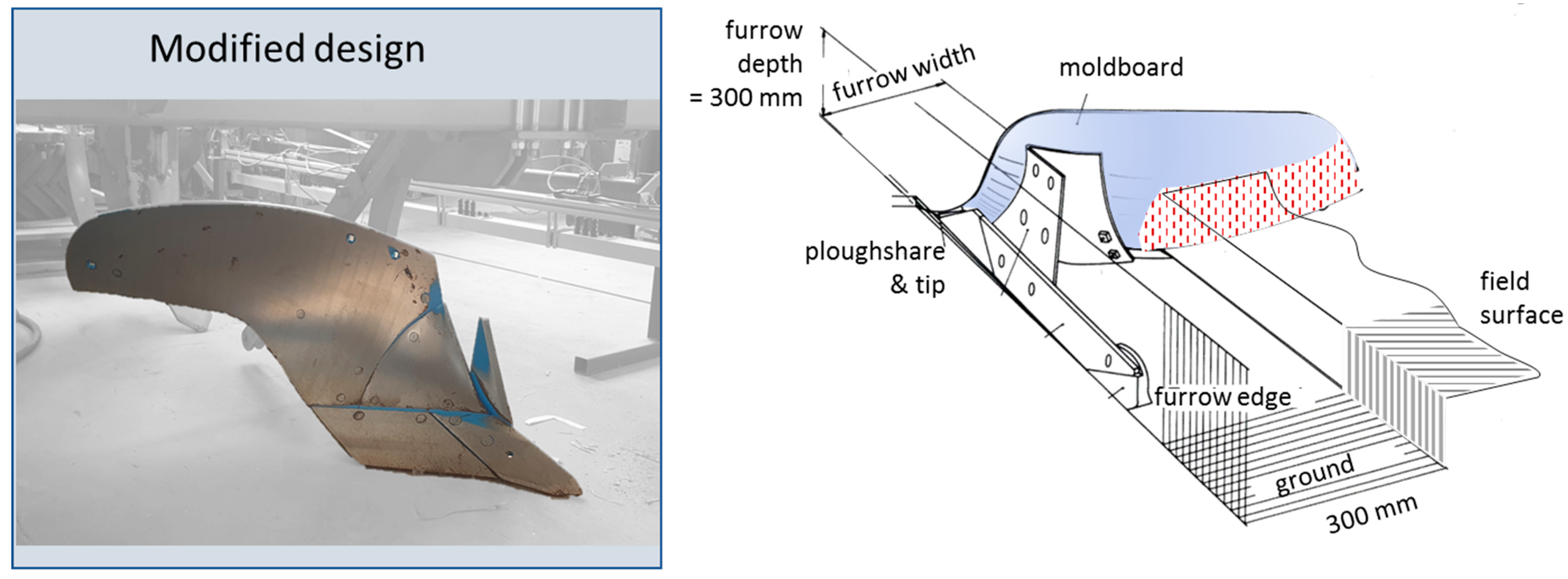
Under the requirement of reducing installation space and power requirements while maintaining high reliability, a conventional plow blade with a large moldboard and a blade coulter was selected. To reduce soil throwing force and to allow furrow channel formation of 30 × 30 cm, the moldboard was modified accordingly based on field tests (Figure 4).
The share width is 30 cm. The upper part of the moldboard is responsible for pushing the topsoil right to the furrow. It has to be taken into account, that the topsoil neither rolls back into the same furrow nor into the neighboring one.
- c.
- Injection tine
The injection tine with the drop channel (Figure 5) is the central tool for the process. It runs inside the furrow walls with a depth of 60 cm. The furrow share loosens the subsoil intensively and guides the soil upwards, then back along with the tine carrier, where the now loosened soil falls back. The possible injection tine width is limited by the available clearance in the furrow. 150 mm has proven to be optimal for loosening and injecting the compost.
The injection tine and its components must ensure reliable injection of the compost into the subsoil avoiding clogging or bridging of the material. The optimal design of the channel was stepwise determined in trials. A key consideration was to leave the channel open at the rear. This has several advantages:
- -
- clogging cannot continue upward
- -
- the sides of the open hopper can vibrate slightly, resulting in self-cleaning.
The funnel width on top is about 350 mm to secure catching the compost from the metering auger above. The width is reduced downwards to 150 mm.
The mixing of subsoil and compost occurs passively-without energy input. The compost is directed downstream through a guide flap installed at the bottom of the injection channel. The point of entry is adjusted by angular adjustment to achieve a mixing of soil and compost. Organic material (type, particle size and moisture) and soil type, moisture and density are the influencing variables. For each condition the flap has to be adjusted and checked.
- a.
- Post-mix tines
In case of insufficient mixing quality, there is the option to mount a post-mix tine on the frame. For remix and not to loosen additional soil, the tine is only approx. 8 cm wide and the working depth is 55 cm. A conventional cultivator tine with goosefoot or chisel share is suitable for this task.
- b.
- Levelling blades
The levelling blades guide the topsoil back into the furrow. It is not necessary to adjust the depth of the blades, as the process is defined for one depth. Accordingly, the support is fixed directly to the supporting frame. In order to respond to different soils, the blades can be adjusted in their angle.
- c.
- Depth guidance and support
Due to the high masses and the required constant working depths of the individual tools, depth guidance and support is of major importance. The implement is hooked up by the tractor rear linkage, resulting in better traction efficiency. Support wheels ensure that the desired working depth of the levelling blades is not exceeded.
A lift on the ground frame ensures a gap between the scraper blade (30 cm) and the injection tine (60 cm) but also allows slight adjustments on uneven surfaces.
- d.
- Compost metering and storage
Since compost must be safely fed from the storage tank through the injection tine into the soil, the tank has been placed on the separate frame. Although this concept results in less favorable weight distribution, it is a compromise in favor of functional safety.
Compost and similar organic materials are difficult to dose: They exhibit high adhesion and cohesion forces and thus tend to clump and bridge. This has to be counteracted technically.
Two agitator shafts continuously homogenize the compost material. When designing the tank (Figure 6), care was taken to have as little dead volume as possible in which stirring cannot take place. On the other hand, the drive torques of the agitator shafts must not be too high. The tank has a width of 2250 mm, so that there is still space on the side for the drive elements for the agitator shafts. The tank geometry was designed to ensure that the compost slides towards the metering augers. Therefore, the adhesion forces between compost and the metal plate have to be overcome. The tank, agitator, and metering unit, including the hydraulic system, form a stable unit and can be assembled and disassembled with little effort.
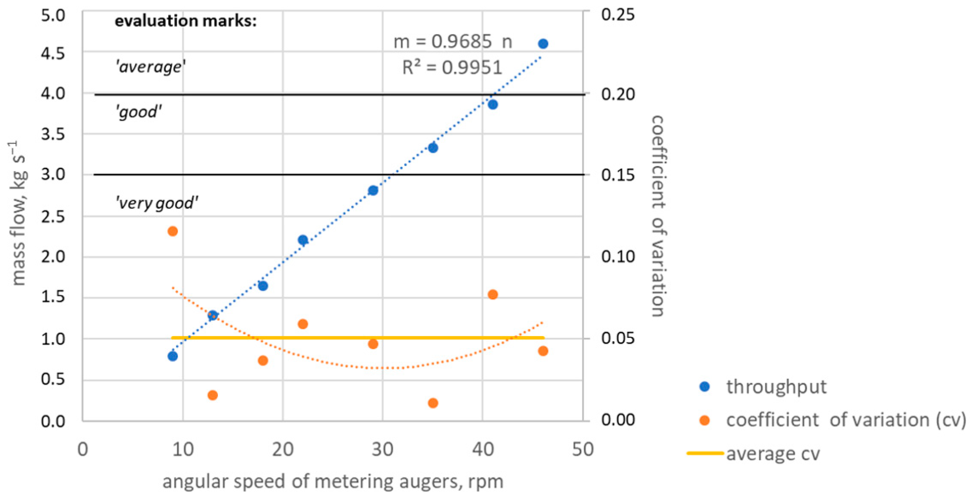
Three open metering augers at a distance of one meter are placed in the bottom of the tank. They take up the material from the tank and discharge it via the respective injection tine. The screw diameter was selected to ensure a reliable flow of the material from the tank into the screw. Bridging over the screw must be prevented and its complete filling ensured. On the other hand, the material must be accurately metered and fed to the injection tine via a hydraulic flow valve. A shaft diameter of 300 mm proved to be optimal for the materials investigated. Depending on the driving speed, the empirically determined necessary auger speeds of 25 to 55 rpm are suitable for the targeted output quantity of 1–10 kg m−1.
A separate hydraulic circuit has been developed for the mixing and metering operations (Figure 7). A hydraulic pump as propulsion for the hydraulic motors is driven by the tractor PTO. One circuit controls the mixing device in the tank. Synchronization of the two mixing shafts is neither desired nor necessary.
The second hydraulic circuit controls the metering by individual hydraulic motors.
The required torque of 200 Nm was determined with a torque wrench. The angular speed of the motors and thus the application rate can be controlled via a manually or electrically adjustable flow valve with a downstream flow divider. The flow divider ensures the synchronization of the three shafts by interlocking mechanical connection.
3.2. Technology Evaluation
3.2.1. Dosing Quality
3.2.2. Mixing Quality
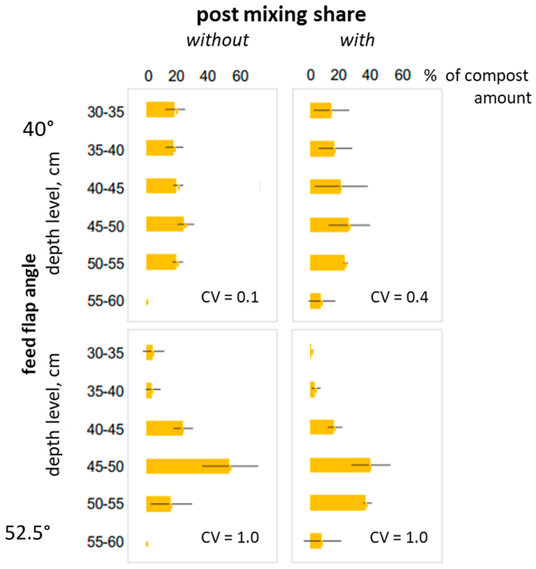
The mixing quality of the compost with the subsoil is influenced by the setting of the guide flap in the injection channel. The angle must be adjusted in a way that the compost is directed into the stream of receding soil. The angle setting is therefore also dependent on the soil type as clay and sandy soils have different flow characteristics. A post-mix coulter can additionally influence the mixing quality.
Accordingly, two flap settings (40 and 52.5°) represented by the angle between soil surface and flap were compared with and without mixing coulter. The means and deviations of the mixed mass for each depth levels and their CVs are shown in Figure 9. The flap angle of 40° and thus higher mixing-in point shows a lower CV than the one at 52.5°. The post-mixing coulter shows the effect of increasing amount in lower layers. The results of the test show that a post-mixing coulter should not be used under these conditions.
3.2.3. Quality of Work in the Field
In Figure 10 the work quality after the subsoil melioration is illustrated by photos. The stripe depth was about 56 cm. It can be seen that the mixing of the compost in the B horizon was successful and there was no mixing of the A and B horizons (left photo). The top layer soil next to the stripe is undisturbed and its structure is unaffected.
The levelling blades complete the melioration and ensure that on the one hand the removed A-horizon is returned to the furrow, and on the other hand that the surface of the field is prepared for successive tillage. On the right photo the loosened soil surface with the melioration stripes can be seen. The following tillage can be preferably performed by a cultivator with lower energy demand.
3.3. Agronomical Evaluation of the Soil3 Procedure
The tests included compost and green cuttings in comparison to pure deep loosening and a control variant without melioration.
In 2017, 6 months after melioration, the crop rotation started with spring barley, followed by winter wheat, winter barley and oats on the same site.
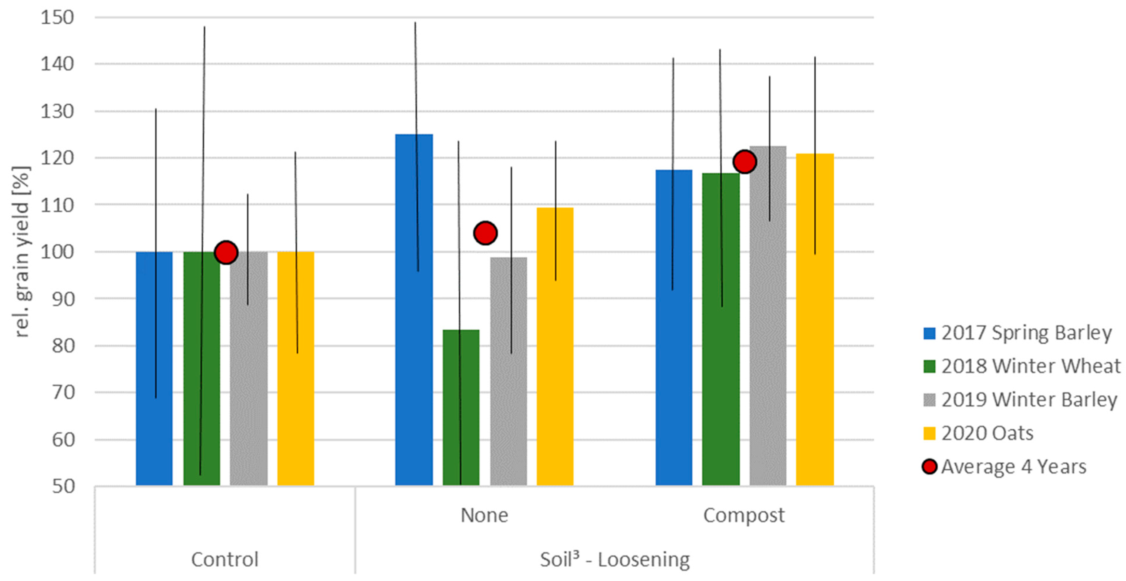
The respective relative yields (Figure 11) are shown in columns, the mean values of the variants as dots. Significant effects are visible, but not statistically validated–caused by the high standard deviations. Deep loosening alone sometimes shows higher, sometimes lower yields but in average the grain yield was 5% higher.
The effects of deep loosening with compost are obvious. In each year, the average yield was 20% higher than the control.
How long higher yield can be achieved has to be investigated in future.
3.4. Summary of the Machine Concept
A device for subsoil melioration in stripes with simultaneous admixing of organic material has been developed (Figure 12). The individual subassemblies were developed in separate and developed processes, optimized and tested in the field according to the procedural requirements. The implement has been assessed in field experiments on light and heavy soils with low stone content.
The incorporation of the compost is done in one operation, and is precisely placed on the ground level. The mixing of soil and compost was rated with a CV of approximately 0.15 according to the score “very good”.
The working width of the implement is 3 m. It was deployed on stubble fields and in standing catch crop with good success. Travel speeds of up to 4 km h−1 can be achieved. Higher speeds are not recommended due to the reaction times of the tractor driver in case of disturbances. The power requirement is about 200 kW, depending on the soil type and status. To avoid high wheel-slip the tractor has to be appropriately ballasted in field work.
For truck transportation the machine can be dismounted into two parts.
4. Conclusions
An innovative implement for subsoil-melioration with admixing non-liquid organic materials into subsoil has been developed. The device has a modular design. Each assembly corresponds to a function and has been individually designed and tested.
The challenge of an undisturbed and functional soil and material flow has been solved. The passive mixing process of soil and compost requires individual adjustment. The constructive implementation of the mixing device into the machine requires minimal installation space and no active tools. The requirement not to mix topsoil and subsoil and to mix the compost into the subsoil only was also met.
The working quality of the machine and each of their components were tested with good results and can be described as high.
With a working width of 3 m, a mass of less than 3 t (depending on the compost filling) and a possible working speed of up to 1.5 m s−1, the melioration equipment is suitable for practical use.
The prerequisite is a deep, rock-free soil. The integrated safety device protects against damage when medium stones are encountered.
The melioration method could be applied in typical arable crop rotations. Melioration in the fall, followed by an intercrop and the cultivation of a spring crop in the following year has been proven successfully.
Multi-year trial results were presented. Up to 20% higher grain yield has been demonstrated in field trials under farm conditions. The increase of yield and its sustainability is only proved for deep loosening with additional structure-stabilizing compost in the subsoil. Intensive deep loosening without structure-stabilizing substrates cannot be recommended on the basis of our study. The problem of evaluation beneficial long-term effects of subsoiling can be confirmed [5].
The Soil3-procedure is applicable on field scale. Further studies on choice of organic material and their optimal amount must now follow and need to be evaluated agronomically.
In future, this technology allows more studies on utilization of subsoil resources of water and nutrients for crops considering dry periods in the vegetation period due to climate change.
5. Patents
The principle of subsoil melioration in stripes with admixing of organic material and the developed technology is patent pending (DE102018120092A1) [20].
Author Contributions
Conceptualization, O.S.; methodology, O.S.; validation, O.S., A.C. and P.S.L.; formal analysis, O.S., A.C. and P.S.L.; investigation, O.S. and A.C.; resources, O.S., A.C. and P.S.L.; data curation, O.S. and A.C.; writing—original draft preparation, O.S.; writing—review and editing, O.S., A.C. and P.S.L.; visualization, O.S. and A.C.; supervision, O.S. and P.S.L.; project administration, O.S. and P.S.L.; funding acquisition, O.S. and P.S.L. All authors have read and agreed to the published version of the manuscript.
Funding
This research was financially funded by the German Federal Ministry of Education and Research (BMBF), grant number 031B0515.
Data Availability Statement
Data sharing not applicable.
Acknowledgments
As a part of the BonaRes program, the authors would like to thank all contributors to the Soil3 project and the team of the research farm Campus Klein-Altendorf for their support.
Conflicts of Interest
The authors declare no conflict of interest. The funders had no role in the design of the study; in the collection, analyses, or interpretation of data; in the writing of the manuscript, or in the decision to publish the results.
References
- Seneviratne, S.I.; Luthi, D.; Litschi, M.; Schar, C. Landatmosphere coupling and climate change in Europe. Nature 2004, 443, 205–209. [Google Scholar] [CrossRef] [PubMed]
- Davies, W. Root signals and the regulation of growth and development of plants in drying soil. Annu. Rev. Plant Physiol. Plant Mol. Biol. 1991, 42, 55–76. [Google Scholar] [CrossRef]
- Angers, D.A.; Caron, J. Plant-induced changes in soil structure: Processes and feedbacks. Biogeochemistry 1998, 42, 55–72. [Google Scholar] [CrossRef]
- Batey, T. Soil compaction and soil management—A review. Soil Use Manag. 2009, 25, 335–345. [Google Scholar] [CrossRef]
- Schneider, F.; Don, A.; Hennings, I.; Schmittmann, O.; Seidel, S.J. The effect of deep tillage on crop yield—What do we really know? Soil Tillage Res. 2017, 174, 193–204. [Google Scholar] [CrossRef]
- Schulze Lammers, P.; Schmittmann, O. Schlitzsägerät für die einphasige Aussaat von Zuckerrüben. Landtechnik 2014, 69, 139–142. [Google Scholar] [CrossRef]
- Cai, H.; Ma, W.; Zhang, X.; Ping, J.; Yan, X.; Liu, J.; Yuan, J.; Wang, L.; Ren, J. Effect of subsoil tillage depth on nutrient accumulation, root distribution, and grain yield in spring maize. Crop J. 2014, 2, 297–307. [Google Scholar] [CrossRef] [Green Version]
- Ghosh, P.K.; Mohanty, M.; Bandyopadhyay, K.K.; Painuli, D.K.; Misra, A.K. Growth, competition, yield advantage and economics in soybean/pigeonpea intercropping system in semi-arid tropics of India. Field Crop. Res. 2006, 96, 80–89. [Google Scholar] [CrossRef]
- Blanco-Canqui, H.; Wienhold, B.J.; Jin, V.L.; Schmer, M.R.; Kibet, L.C. Long-term tillage impact on soil hydraulic properties. Soil Tillage Res. 2017, 170, 38–42. [Google Scholar] [CrossRef] [Green Version]
- Hartmann, C.; Poss, R.; Noble, A.D.; Jongskul, A.; Bourdon, E.; Brunet, D.; Lesturgez, G. Subsoil improvement in a tropical coarse textured soil: Effect of deep-ripping and slotting. Soil Tillage Res. 2008, 99, 245–253. [Google Scholar] [CrossRef]
- Kirkegaard, J.A.; Lilley, J.M.; Howe, G.N.; Graham, J.M. Impact of subsoil water use on wheat yield. Aust. J. Agric. Res. 2007, 58, 303. [Google Scholar] [CrossRef]
- Zhang, Y.; Wang, R.; Wang, S.; Wang, H.; Xu, Z.; Jia, G.; Wang, X.; Li, J. Effects of different sub-soiling frequencies incorporated into no-tillage systems on soil properties and crop yield in dryland wheat-maize rotation system. Field Crop. Res. 2017, 209, 151–158. [Google Scholar] [CrossRef]
- Evanylo, G.; Sherony, C.; Spargo, J.; Starner, D.; Brosius, M.; Haering, K. Soil and water environmental effects of fertilizer-, manure-, and compost-based fertility practices in an organic vegetable cropping system. Agric. Ecosyst. Environ. 2008, 127, 50–58. [Google Scholar] [CrossRef]
- Diacono, M.; Montemurro, F. Long-term effects of organic amendments on soil fertility. A review. Agron. Sustain. Dev. 2010, 30, 401–422. [Google Scholar] [CrossRef] [Green Version]
- Abiven, S.; Menasseri, S.; Chenu, C. The effects of organic inputs over time on soil aggregate stability—A literature analysis. Soil Biol. Biochem. 2009, 41, 1–12. [Google Scholar] [CrossRef]
- Freibauer, A.; Rounsevell, M.D.; Smith, P.; Verhagen, J. Carbon sequestration in the agricultural soils of Europe. Geoderma 2004, 122, 1–23. [Google Scholar] [CrossRef]
- Silber, W. Vorrichtung zur Bewässerung von Reihenkulturen in Trockenzonen. German Patent DE 10 2014 005 054 A1, 8 October 2015. [Google Scholar]
- Reich, J.; Unger, H.; Streitenberger, H. Verfahren und Vorrichtung zur Verbesserung verdichteter Unterböden. German Patent DD000000233915A1, 19 March 1986. [Google Scholar]
- Nicholson, C. Solving the Commercial Constraints Preventing Adoption of Subsoil Ameloration in South West Victoria; S. 9f; SFS Ltd.: Inverleigh, VIC, Australia, 2016. [Google Scholar]
- Deutsches Patent-und Markenamt 2018. Verfahren zur Bodenbearbeitung und/oder zur Bodenmodifikation durch Einbringen von Wachstumsförderndem Organischem Material in Einen Ackerboden. German Patent DE102018120092A1, 20 February 2020. [Google Scholar]
- Jakobs, I.; Schmittmann, O.; Schulze Lammers, P. Short-term effects of in-row subsoiling and simultaneous admixing of organic material on growth of spring barley (H. vulgare). Soil Use Manag. 2017, 33, 620–630. [Google Scholar] [CrossRef]
- Jakobs, I.; Schmittmann, O.; Athmann, M.; Kautz, T.; Lammers, P.S. Cereal Response to Deep Tillage and Incorporated Organic Fertilizer. Agronomy 2019, 9, 296. [Google Scholar] [CrossRef] [Green Version]
- DLG. DLG-Prüfbericht 6045F—Verteilqualität Stallmist und Kompost; S. 1; Deutsche Landwirtschafts-Gesellschaft e.V.: Groß-Umstadt, Germany, 2011. [Google Scholar]
- DüV; Bundesministerium fuer Justiz und Verbraucherschutz. Verordnung über die Anwendung von Düngemitteln, Bodenhilfsstoffen, Kultursubstraten und Pflanzenhilfsmitteln nach den Grundsätzen der guten fachlichen Praxis beim Düngen2. Available online: http://www.gesetze-im-internet.de/d_v_2017/ (accessed on 10 August 2021).
- EU. Regulation (EU) No 1306/2013 of the European Parliament and of the Council of 17 December 2013. Off. J. Eur. Union 2013, 347, 549–607. [Google Scholar]
- DIN EN 13080. Stalldungstreuer—Umweltschutz—Anforderungen und Prüfmethoden, Deutsche Industiernorm; Beuth Verlag GmbH: Berlin, Germany, 2003. [Google Scholar]
- VDI-RICHTLINIE 2221. Methodik zum Entwickeln und Konstruieren technischer Systeme und Produkte; VDI: Düsseldorf, Germany, 1993. [Google Scholar]
- VDI-RICHTLINIE 2222. Methodisches Entwickeln von Lösungsprinzipien; VDI: Düsseldorf, Germany, 1997. [Google Scholar]
- FAO; Iuss Working Group Wrb. World reference base for soil resources 2014, update 2015: International soil classification system for naming soil and creating legends for soil maps. World Soil Resour. Rep. 2015, 106, 192. [Google Scholar]
- SPSS. Statistical Package for the Social Sciences; Version 27; IBM: Armonk, NY, USA, 2020. [Google Scholar]
- AutoDesk: Inventor 2020 Professional; Autodesk GmbH: Muenchen, Germany, 2019.
- StVO. Available online: https://www.stvo.de/strassenverkehrsordnung/105-22-ladung (accessed on 19 August 2021).
Figure 1.
Soil3 subsoil melioration principle and the expected Gaussian biomass distribution above the stripe.
Figure 1.
Soil3 subsoil melioration principle and the expected Gaussian biomass distribution above the stripe.

Figure 2.
Phases of the Soil3 melioration process and selected photos of the technology from the preliminary tests for tool selection and design.
Figure 2.
Phases of the Soil3 melioration process and selected photos of the technology from the preliminary tests for tool selection and design.

Figure 3.
Scheme of the technology concept of a single-phase machine to be developed.

Figure 4.
Modifications of the scraper blade for furrow forming.

Figure 5.
Injection tine. Components (left), material flow and mixing process (right) of compost (green) and subsoil (brown).
Figure 5.
Injection tine. Components (left), material flow and mixing process (right) of compost (green) and subsoil (brown).

Figure 6.
Compost tank with two hydraulically driven mixing and three metering augers.

Figure 7.
Scheme of the hydraulic system for compost mixing and metering.

Figure 8.
Mass flow versus angular speed of the metering augers and dosing quality rated by the coefficient of variation according to DLG test framework.
Figure 8.
Mass flow versus angular speed of the metering augers and dosing quality rated by the coefficient of variation according to DLG test framework.

Figure 9.
Mixing quality of compost and subsoil and impact of an additional mixing coulter for different feed flap settings, rated by the coefficient of variation and distribution (%) in the different layers.
Figure 9.
Mixing quality of compost and subsoil and impact of an additional mixing coulter for different feed flap settings, rated by the coefficient of variation and distribution (%) in the different layers.

Figure 10.
Melioration stripes with mixed compost (left) and field surface after melioration (right).
Figure 10.
Melioration stripes with mixed compost (left) and field surface after melioration (right).

Figure 11.
Yield-effects after subsoil-melioration with and without organic material in a grain crop rotation on a high-yielding site.
Figure 11.
Yield-effects after subsoil-melioration with and without organic material in a grain crop rotation on a high-yielding site.

Figure 12.
The developed prototype for Soli3 subsoil melioration.


Table 1.
Requirements for the design of the Soil3-melioration technology.
| Functional Requirements | Priority | |
|---|---|---|
| F1 | Working depth 60 cm | P1 |
| F2 | Removal of topsoil | P1 |
| F3 | Injection of organic material into subsoil | P1 |
| F4 | Mixing of different organic substrates only into subsoil | P1 |
| F5 | Recompaction | P2 |
| F6 | Levelling after injection | P1 |
| F7 | Tank for compost | P1 |
| Working Requirements | Priority | |
| W1 | Process in one phase | P1 |
| W2 | Working quality (no mixing of top- and subsoil) | P1 |
| W3 | Working quality (no organic material in subsoil) | P2 |
| W4 | Blockage-free soil preparation and admixing | P1 |
| W5 | Protection against destruction and overload | P1 |
| W6 | Soil protection | P2 |
| W7 | Low-maintenance technology | P2 |
| Interface Requirements | Priority | |
| I1 | Compatible for tractor use | P1 |
| I2 | Mounted on tractors | P1 |
| I3 | Compatible to road traffic | P2 |
| I4 | Transportability for truck | P1 |
Publisher’s Note: MDPI stays neutral with regard to jurisdictional claims in published maps and institutional affiliations. |
© 2021 by the authors. Licensee MDPI, Basel, Switzerland. This article is an open access article distributed under the terms and conditions of the Creative Commons Attribution (CC BY) license (https://creativecommons.org/licenses/by/4.0/).
Share and Cite
MDPI and ACS Style
Schmittmann, O.; Christ, A.; Schulze Lammers, P. Subsoil Melioration with Organic Material—Principle, Technology and Yield Effects. Agronomy 2021, 11, 1970. https://0-doi-org.brum.beds.ac.uk/10.3390/agronomy11101970
AMA Style
Schmittmann O, Christ A, Schulze Lammers P. Subsoil Melioration with Organic Material—Principle, Technology and Yield Effects. Agronomy. 2021; 11(10):1970. https://0-doi-org.brum.beds.ac.uk/10.3390/agronomy11101970
Chicago/Turabian StyleSchmittmann, Oliver, Andreas Christ, and Peter Schulze Lammers. 2021. "Subsoil Melioration with Organic Material—Principle, Technology and Yield Effects" Agronomy 11, no. 10: 1970. https://0-doi-org.brum.beds.ac.uk/10.3390/agronomy11101970
Note that from the first issue of 2016, this journal uses article numbers instead of page numbers. See further details here.