Article

On the Influence of Volumetric Energy Density and Inter-Layer Time on the Material Properties of Case-Hardening Steels

1
Institute of Photonic Technologies (LPT), Friedrich-Alexander-Universität Erlangen-Nürnberg (FAU), Konrad-Zuse-Straße 3/5, 91052 Erlangen, Germany
2
Erlangen Graduate School in Advanced Optical Technologies (SAOT), Friedrich-Alexander-Universität Erlangen-Nürnberg (FAU), Paul-Gordan-Straße 6, 91052 Erlangen, Germany
*
Author to whom correspondence should be addressed.
Submission received: 19 June 2023 / Revised: 11 August 2023 / Accepted: 23 August 2023 / Published: 25 August 2023
(This article belongs to the Special Issue Design of New Metallic Alloys for AM)

Abstract

:
Case-hardening steels are gaining increasing interest in the field of laser powder bed fusion (PBF-LB/M) due to their excellent weldability. In combination with post-process carburization heat treatment, the surface properties can be improved to generate high-strength products. When manufacturing larger products by means of PBF-LB/M, the in situ heat accumulation and the altered cooling rates affect the resulting material properties. Therefore, the fabrication of larger products requires an understanding on the influencing factors that affect the material properties. This work investigates the effect of different volumetric energy densities (VED) on the resulting microstructural and mechanical properties. It is found that the hardness decreases continuously along the build direction. The gradient depends on the applied energy and is stronger for higher energy inputs due to heat accumulation and lowered cooling rates. Furthermore, countering strategies are investigated to avoid process-specific hardness reduction along the build direction. This includes a reduced number of parts within the build job as well as a modified inter-layer time (ILT) between consecutive layers of the specimen. Applying a moderate inter-layer time helps to counter process-specific overheating, which is indicated by an almost homogeneous material hardness and melt pool size along the build direction.

1. Introduction

Case-hardening steels like 16MnCr5 and 20MnCr5 are used for a variety of different applications due to their beneficiary material properties. Their good ductility facilitates the processing using shaping technologies, while their excellent carbon diffusivity supports the local hardening of the material for later use [1]. Typical products are shafts, gearings, or bearing applications. By exposing these specimens to a carbon- or nitrogen-rich atmosphere at elevated temperatures, these elements diffuse into the case of the material and improve the hardenability of the material [2]. The resulting microstructure (e.g., martensite or iron nitrides) leads to a high surface hardness, which is required for the aforementioned applications [3]. When aiming at optimizing these products or at expanding the application portfolio of this class of materials even further, conventionally established processes like forming reach their limitations [4]. Additive manufacturing processes like laser powder bed fusion of metals (PBF-LB/M), however, enable the generation of highly complex structures with bionic [5] or load-adapted geometries [6]. This high freedom of design facilitates the integration of, e.g., complex cooling/tempering and lightweight structures to improve performance and longevity of the final product [7].
Reviewing the literature reveals that these low-alloyed steels like 16MnCr5 [8] and 20MnCr5 [9] have recently been processed with great success. The works by Schmitt et al. [10,11] show that this class of material can be processed without larger defects. Further investigations focused on the case-hardenability of additively manufactured case-hardening steels [12,13]. Comparable hardness values could be obtained after hardening even though the process-specific fine microstructure might negatively affect the carbon diffusion. Furthermore, the first approaches in the field of in situ alloying were carried out for the low-alloyed steel 16MnCr5 with the goal of substituting these energy-intensive carburizing processes [14,15]. When aiming at avoiding these processes, e.g., via the application of in situ alloying approaches, a profound understanding on the microstructure formation in the as-built state is necessary. The first investigations by Schmitt et al. [11] and Aumayr et al. [13] state that a bainitic–martensitic microstructure is achieved when processing low-alloyed steels by means of PBF-LB/M. The material properties were thereby concluded based on the underlying hardness, which is typically lower than the one of martensite but higher than the one of lower-strength microstructure constituents like ferrite. In-depth investigations by Bartels et al. [16] using a different case-hardening steel show that a predominantly bainite-like microstructure is achieved when processing low-alloyed steels by means of PBF-LB/M.
However, for completely exploiting the potential of the PBF-LB/M process, manufacturing strategies are required that facilitate the defect-free fabrication of structures that are larger than that of the typically investigated small cubic specimens with an edge length of 10 mm [16] or even only 6 mm [17]. One major issue is the formation of defects along the build direction. PBF-LB/M parts are typically characterized by several defects like (micro-)crack formation, lack-of-fusion, and gas porosity defects [18]. Whereas cracks typically do not occur for low-carbon materials like case-hardening steels, lack-of-fusion defects can be avoided by selecting a sufficiently high energy for melting the powder [19,20]. In doing so, the formation of pores, which is typically the consequence of an excessive energy input during PBF-LB/M [21,22], needs to be avoided.
Mohr et al. [23,24] have found that the layer-by-layer approach in PBF-LB/M can result in an excessive heat accumulation along the build direction. This heat accumulation acts as in situ platform preheating and lowers the required energy input for melting the material. Due to the consequently reduced energy delta required for melting the material in higher layers, an increased porosity can be observed along the build height in PBF-LB/M. High volumetric energy densities (VEDs) result in high penetration depths of the melt pool into the underlying material. In contrast, lower VEDs reduce the penetration depth since the overall energy input is reduced. Similar observations were made by Keshavarzkermani et al. [25]. These altered melt pool geometries again affect the thermal gradients during PBF-LB/M. Smaller melt pools are characterized by a faster cooling [26]. Larger melt pools, in contrast, result in a slower cooling of the structure. Thus, the corresponding hardness will be lower for higher VEDs since hardness-beneficiary effects like fine-grain hardening are not as pronounced as for lower VEDs [27]. The first investigations by Schmitt et al. [11] have shown that when fabricating larger specimens, the altered cooling gradients and in situ heat treatments during PBF-LB/M result in a reduced hardness along the build direction. Similar effects can be observed for other materials like AlSi10Mg [28] and 316L [23].
Another decisive factor for influencing this overheating is the time that lies between the manufacturing of two consecutive layers. This time is often referred to as idle time [29] or inter-layer time [30]. Keeping this time at minimum results in the largest penetration depths of the single weld tracks [23]. When increasing the inter-layer time, the penetration depth of the weld track is reduced since the specimen gains more time to dissipate the excessive heat through heat flux. Furthermore, Mohr et al. [23] found that the ratio of area exploitation (which will here be referred to as the number of parts) plays a significant role when designing a build job. This is mainly caused by the fact that the number of parts affects the inter-layer time since less parts require a shorter illumination. Thus, the inter-layer time and the corresponding cooling time is reduced between two layers.
In this work, the influence of different process conditions on the material properties of case-hardening steels are investigated to facilitate the fabrication of larger parts with specific material properties. Since the resulting material properties depend strongly on the design of the build job, two main influencing factors were manipulated. On the one hand, the applied energy for manufacturing the specimens was altered. The aim is to study how different VEDs affect the resulting material properties. On the other hand, the process-specific boundary conditions like the number of parts and the inter-layer time are varied to investigate how adjusted inter-layer times affect the microstructure and hardness. The overarching goal of this work is to derive processing strategies that help to avoid an overheating of the specimens and that support homogeneous material properties. This goal is divided into the following two sub-goals:
  • How does the VED affect the properties, primarily the hardness, of the material for large part heights?
  • Which countering strategies are promising to counter inhomogeneous material properties, primarily the hardness, along the build direction?

2. Materials and Methods

The nitrogen-gas-atomized low-alloyed steel Bainidur AM (Deutsche Edelstahlwerke Speciality Steel GmbH, Krefeld, Germany) was used for performing the experiments. A particle size distribution of 15 to 45 µm was selected for the PBF-LB/M process. The used powder material was mainly spherical. Figure 1 shows the particle shape and the experimentally determined particle size distribution using a CamSizer (Microtrac Retsch GmbH, Haan, Germany).
The powder was dried in a vacuum furnace at 120 °C for twelve hours prior to processing. All experiments were performed on a commercially available PBF-LB/M machine of type AconityMINI (Aconity 3D, Herzogenrath, Germany). The machine was operated with a reduced build envelope that allows smaller amounts of powder to be processed (see Figure 1d). A 1 kW SPI redPower QUBE single-mode fiber laser emitting at a wavelength of 1080 nm was used for the investigations (Southampton, UK). The scanner used was an AxialScan-30 from Raylase GmbH (Wessling, Germany). As substrate, the low-alloyed steel 16MnCr5 (Abrams Stahl, Osnabrück, Germany) was used. Circular blanks with a diameter of 55 mm were laser-cut using a CO2 laser. The thickness of these plates was 6.3 mm. Table 1 shows the chemical composition of the Bainidur AM powder material.

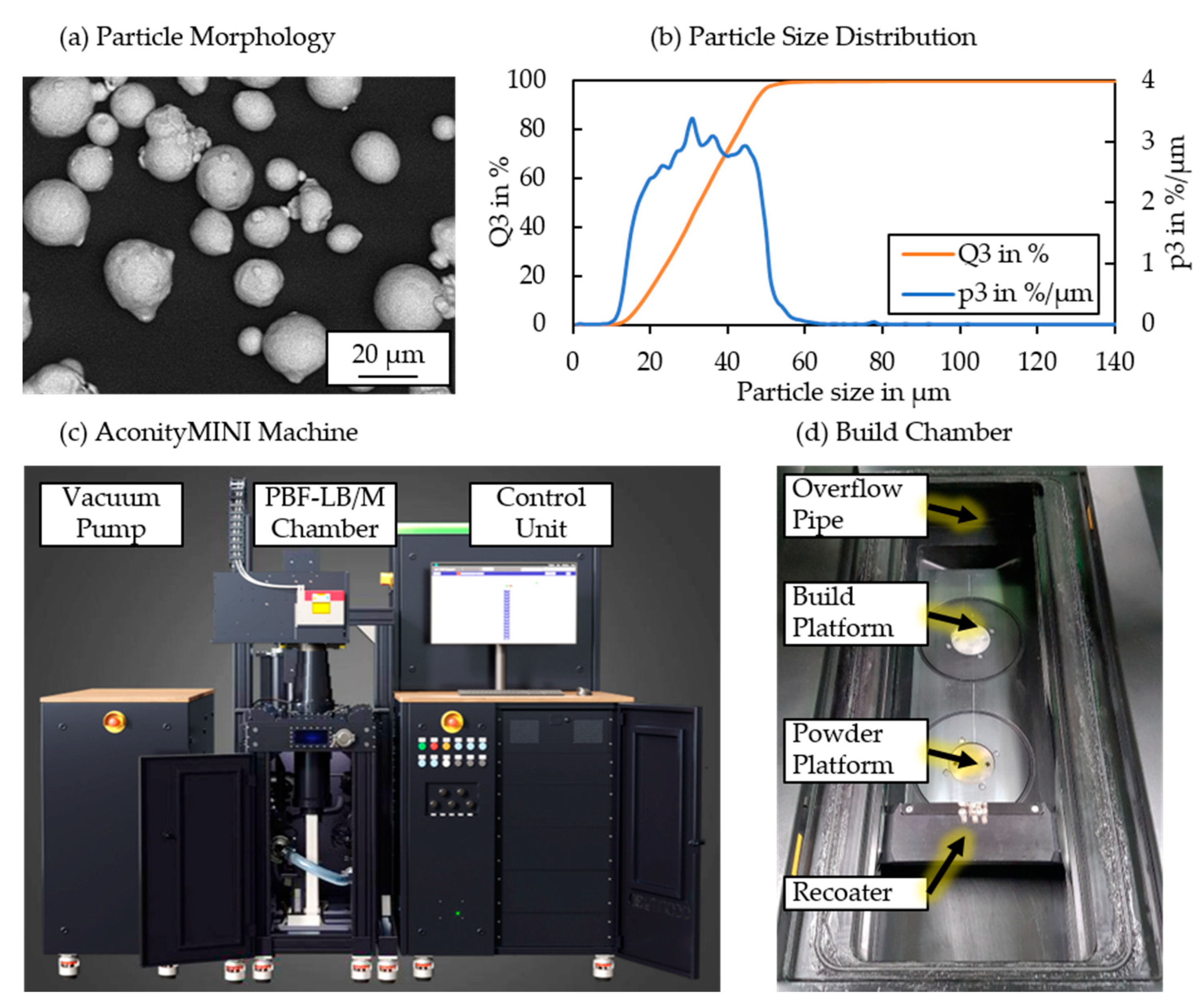
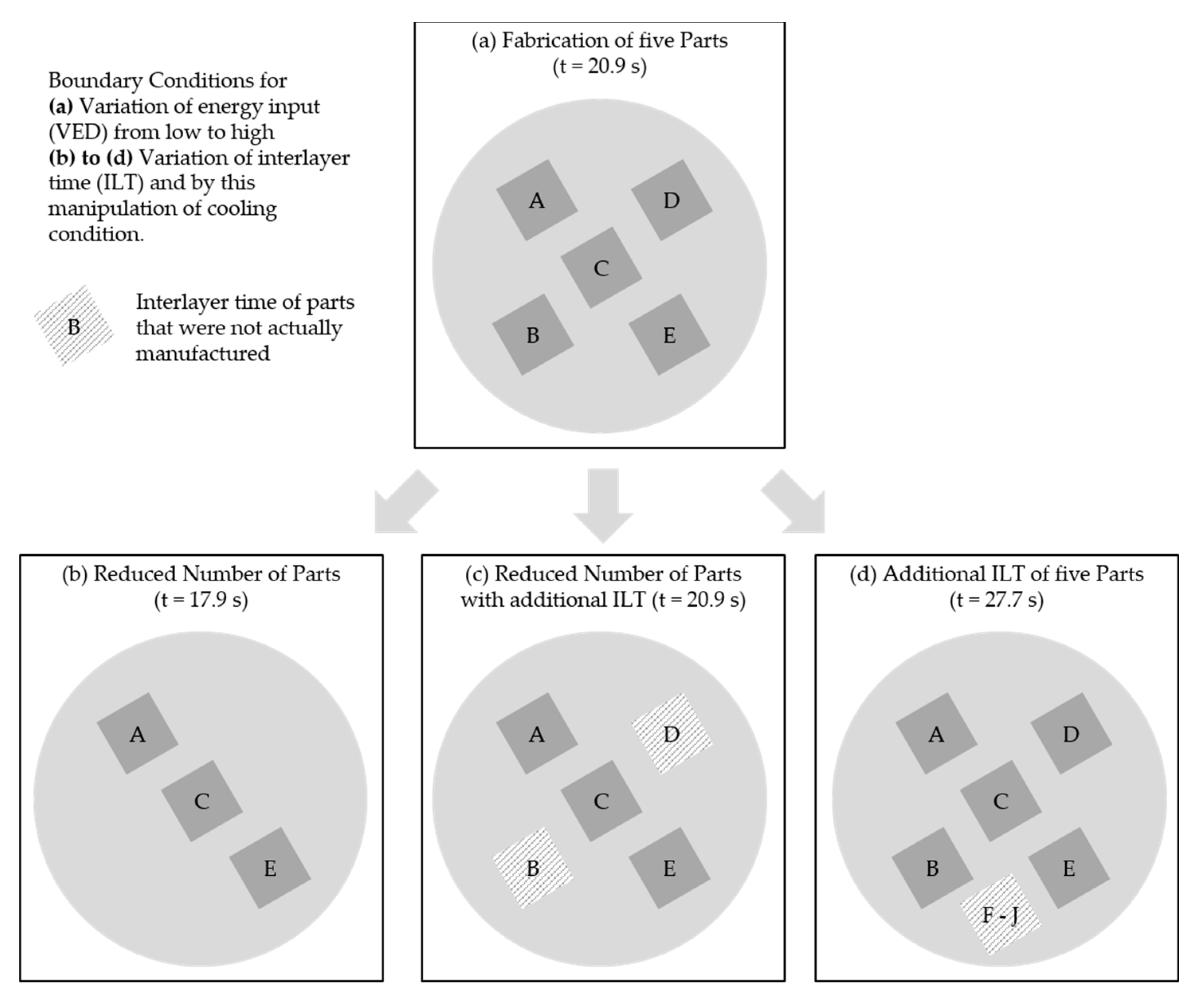
2.1. Sample Fabrication

Different build jobs were designed to investigate the influence of different PBF-LB/M-specific conditions. Thereby, reference investigations were performed using three different VEDs. Five parts were manufactured per build job for these initial investigations. Building on these findings, the number of parts as well as the average time per layer were modified. The methodological approach is presented in Figure 2. The fundamental design of the build job and the part geometry were maintained constant throughout all experiments. Edge length in x- and y-direction was set to 10 mm each, while the part height (z-direction) was set to 60 mm. Layer thickness and laser spot size were kept constant at 60 µm and 105 µm, respectively.
The scanning orientation was rotated by 67° after every layer. Laser power and scanning speed for manufacturing the contour were set to 325 W and 450 mm/s, respectively. No preheating was applied throughout the experiments. In the first step (see Figure 2a), three different volumetric energy densities (VEDs) were studied. Laser spot size was set to 105 µm. The applied process parameters are presented in Table 2. These parameters are oriented at a previous study for the material Bainidur AM [16].
The aim of a decreased VED is to avoid the process-specific overheating, which was already described by Mohr et al. [24]. Correlated with modified VEDs, especially when adjusting hatch spacing or scanning speed, the average time required for manufacturing one layer decreased (see Table 2). This time per layer was averaged over several consecutive layers (>20 layers).
The following investigations regarding the influence of different boundary conditions (Figure 2b–d) were performed using the parameter set VED High. This process parameter was chosen since VED High resulted in the most noticeable hardness gradient along the build direction while still possessing a good relative part density.
In the next step, the number of parts per build job was reduced from five to three specimens (RNP, see Figure 2b). Reducing the number of parts results in a decreased average layer time (from 20.9 s to 17.9 s). Correspondingly, the time for cooling the additively manufactured structures is reduced compared to when five samples are fabricated within one build job. Furthermore, the overall energy input into the substrate during PBF-LB/M is reduced, which could affect overheating effects in the early stages of the process.
Further investigations were performed by building the reduced number of parts (three specimens) with an additional inter-layer time (RNP + ILT, 1.4 s per specimen; in total, 2.8 s). The aim was to add this inter-layer time to make up for the time that is missing when two specimens are removed (see Figure 2c). In combination with the studies using the reference parameter set (Figure 2a) and the reduced number of parts (Figure 2b), this allows the assessment of whether the time per layer or the number of parts is more decisive regarding overheating.
In the final step, a build job with five specimens and an additional inter-layer time, which was equal to five more parts, was designed (see Figure 2d). The average time per layer correspondingly increased from 20.9 s to 27.7 s. After fabrication, all specimens were analyzed regarding their micro- and macroscopic materials. This includes investigations on the relative part density, microstructure formation, and the associated material hardness.

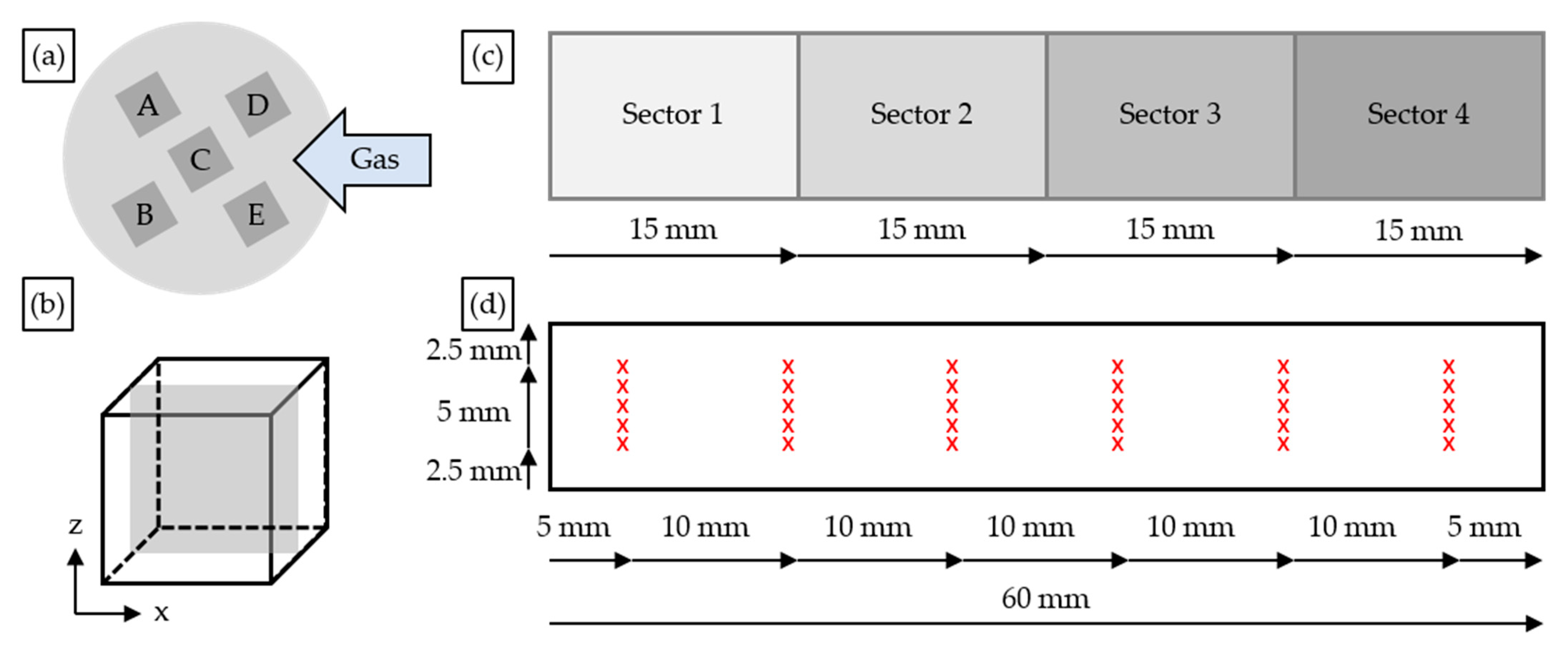
2.2. Sample Preparation

Figure 3 presents the approach for sample preparation. The as-built samples were cold-embedded using an epoxy resin. After solidification of the resin, the specimens were grinded until the center region was reached before polishing the surface down to one µm (exemplary shown in Figure 3b). Next, optical light microscopy was used to analyze the specimens regarding internal defects like pores, lack of fusion, or cracks. A Zeiss microscope was used for generating the images. These images were binarized for determining the residual porosity. After that, the specimen was grinded and polished again to reveal porosity and internal defects in a different position within the specimen. This procedure was repeated three times per sample. Furthermore, the hardness was determined on the polished cross-sections using an indentation tester of type KB30S (Hegewald & Peschke, Nossen, Germany). Since the part height can significantly affect the material properties, the relative part density and hardness were measured in different regions of the specimen. The relative part density was determined in different regions of the specimen (Figure 3c).
The material hardness was determined at specific positions within the specimens (see Figure 3d). Six measurement rows were defined: one in the bottom (after 5 mm), lower half (after 15 mm), middle (after 25 and 35 mm), upper half (after 45 mm) and top (after 55 mm). Six indentations were made per measurement row to determine the hardness. Since specimen D always possessed a high porosity (possibly due to the inert gas flow, indicated in Figure 3a), this sample was spared from the investigations.
After the hardness measurements were performed, the specimens were etched using a 3% Nital etching solution. The microstructure was again analyzed using optical light microscopy. Since the specimens were not polished prior to this etching procedure, the microstructure could be investigated specifically in the regions where the hardness measurements were performed earlier.

3. Results

This section is divided into three sub-sections. In the first step, the relative part density for the different processing strategies is analyzed. The second subsection focusses on the influence on the resulting mechanical material properties. In the third subsection, the underlying microstructure is studied and correlated with the applied processing strategies.

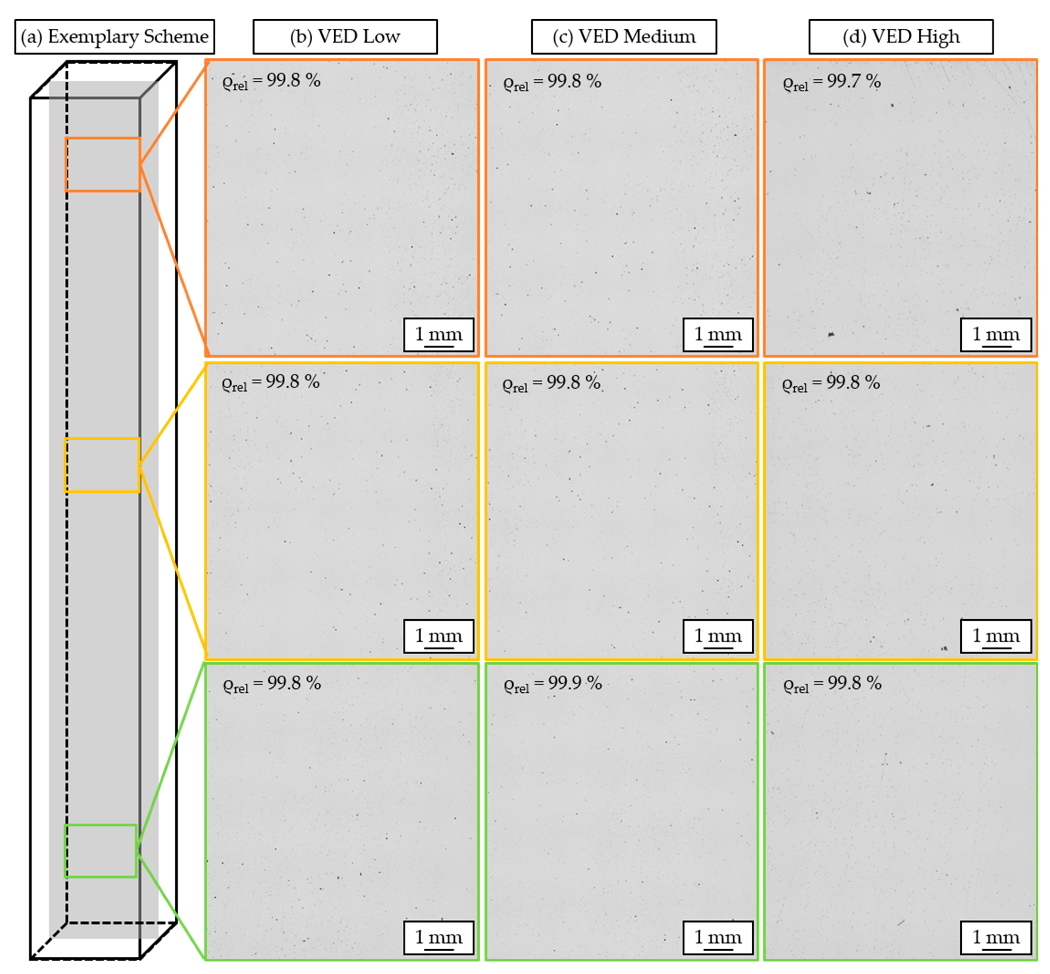
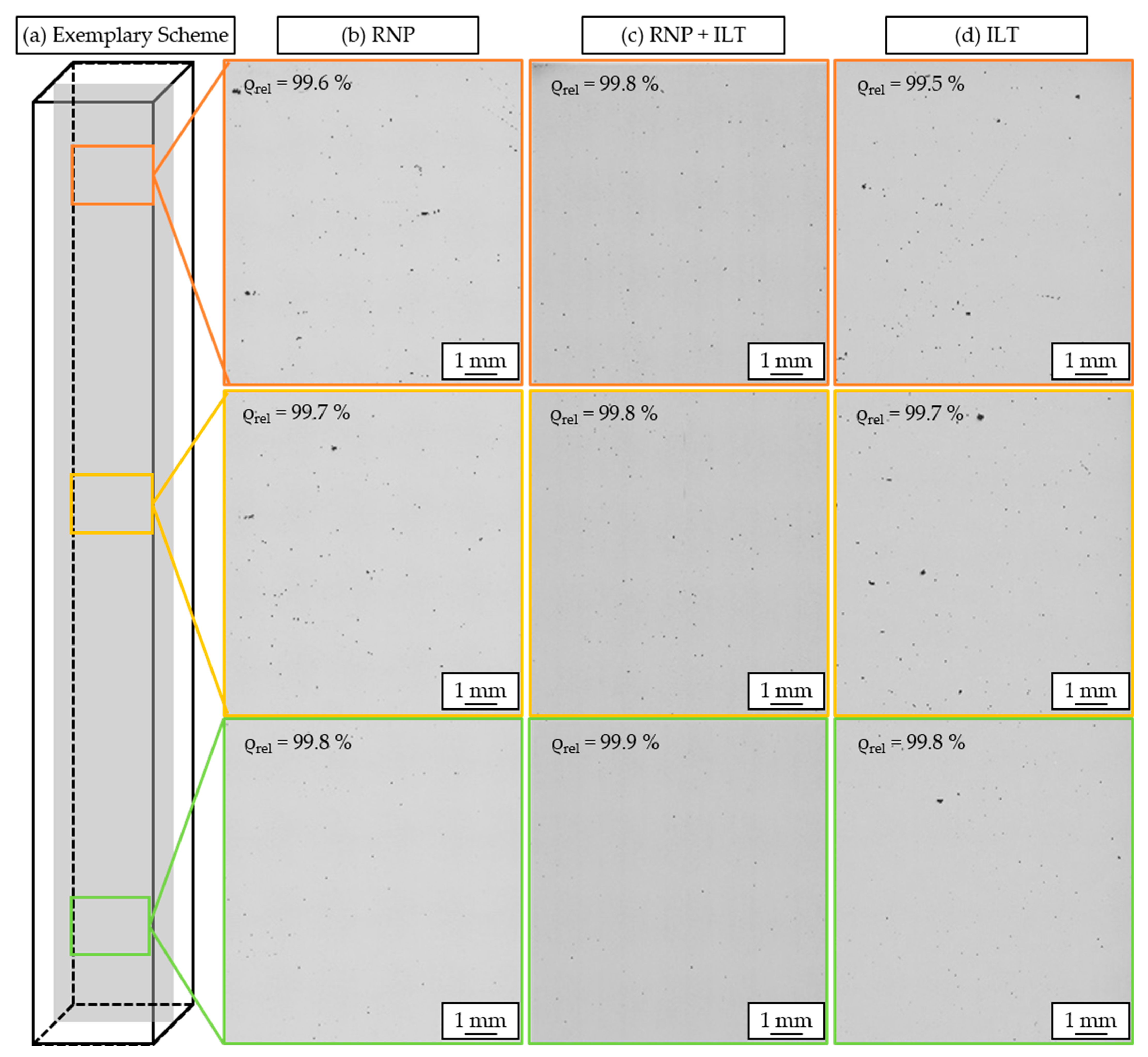
3.1. Relative Part Density

In the first step, the relative part density was assessed for the different VEDs. The part density was determined on longitudinal cross-sections along the build direction. Four specimens were analyzed per build job since one specimen was highly affected by the part positioning on the substrate (specimen D). Figure 4 presents the results on the cross-sections for the different VEDs. Three different regions were thereby selected according to the scheme in Figure 4a. All parameter combinations facilitate the fabrication of almost fully dense specimens. The relative part density exceeds 99.7% in all investigated regions of the specimens. For the parameter combination VED Low, a fine porosity can be identified in the bottom region of the specimen. This potentially could be lack-of-fusion porosity due to an insufficient energy input. With an increasing part height, these defects reduce, which manifests this assumption.
Both VED Medium and VED High also result in a homogeneous relative part density along the build direction. For VED High, a slightly lower relative part density can be observed, which could again be attributed to a partial overheating of the specimen, especially in the higher regions of the sample. Overall, all parameter combinations are characterized by a good part density that exceeds 99.7% in all regions.
Next, the influence of different countering strategies like inter-layer times, and number of parts on the relative part density was studied. The parameter set VED High was chosen for these investigations. Figure 5 shows the cross-sections of the specimens manufactured using the different countering strategies. Reducing the overall number of parts in one build job without adjusting the inter-layer time (RNP, Figure 5a) promotes porosity formation along the build direction. Thereby, mainly spherical pores can be observed. The shape indicated that the pores might be the consequence of keyholing mechanisms during PBF-LB/M, which can result in gas entrapment when the keyhole collapses [21]. However, additional investigations on this topic are required to exclude other mechanisms for the formation of these defects.
When adding an additional inter-layer time equivalent to the time required for manufacturing two specimens (RNP + ILT, Figure 5c), an almost homogeneous porosity along the build direction can be achieved. The porosity is lower compared to both the specimens manufactured with VED High (Figure 5d) as well as the ones with fewer samples (Figure 5a). However, further increasing the inter-layer time to the equivalent of five specimens (Figure 5d, ILT) reduces the relative part density significantly. The defects are shaped asymmetrically, indicating lack-of-fusion defects. Thereby, the inter-layer time was too long to facilitate defect-free fabrication. Comparing the different processing strategies, it is recommended to use as little energy as possible when aiming at fabricating nearly fully dense specimens. To avoid undesired gas porosity defects, the applied VED should be kept as low as possible. Otherwise, overheating effects might negatively affect the porosity with increasing part size. The inter-layer time should further be selected to avoid an excessive cooling of the structure. Increasing the average time per layer by approximately 20% has proven suitable to avoid negative effects on the relative part density.

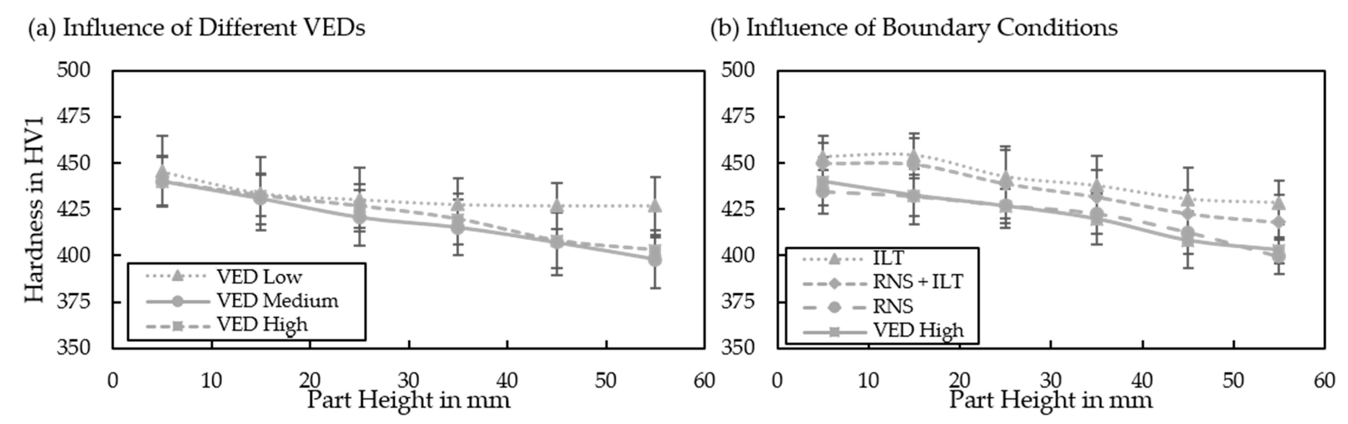
3.2. Microhardness along Build Direction

Since all specimens possess a sufficient relative part density exceeding 99.5%, no negative influence of minor defects like pores or cracks on the resulting hardness is assumed. The hardness was determined in different regions within the samples to assess the impact of the part height on the material properties. Figure 6 shows the hardness propagation for different (a) VEDs and (b) boundary conditions.
For all parameter combinations, the highest hardness was observed in the bottom region of the layer. VED Low, VED Medium, and VED High (see Figure 6a) all possess a similar hardness after a build height of approximately 5 mm. After that, the hardness decreased for all specimens, independently of the applied volumetric energy density. For VED Low, only a minor decrease in the material hardness was detected. The initial hardness of 446 ± 19 HV1 falls to 427 ± 16 HV1 in the top region after manufacturing approximately 55 mm. Applying VED Medium and VED High, a stronger drop-off in hardness is detectable. While the hardness in the bottom region is comparable (440 ± 14 HV1 for VED Medium, 440 ± 13 HV1 for VED High), a similar trend for the hardness fall-off is evident. The hardness in the highest regions of the specimens falls to 398 ± 16 HV1 (VED Medium) and 403 ± 7 HV1 (VED High). This hardness exceeds the one of additively manufactured specimens from Bainidur AM obtained in a previous work by Bartels et al. [16]. The hardness in the bottom regions is somewhere in the middle between the hardness of the as-built (around 405 HV1) and hardened (around 460 HV1) specimens. However, since lower VEDs were applied in this work, a promoted fine-grain hardening can be assumed as one reason for the increased hardness [31]. Another potential explanation might be that powder-aging effects favored oxidation of the material. The oxidized particles would then reinforce the matrix, which could help in explaining the slightly higher hardness in the as-built state [32]. They could also affect the weldability since higher energies are required for a sufficient melting of the material. This could explain the partially increased porosity. Furthermore, the thermal cycle during PBF-LB/M associated with heat accumulation could promote secondary hardening mechanisms like carbide precipitation during the manufacturing process [33].
Figure 6b shows the material hardness for the different countering strategies to reduce the process-intrinsic overheating. The lowest hardness is observed for the specimens manufactured with the reduced number of samples (RNS). Here, the shorter inter-layer time (17.9 s) favors an overheating of the structure. The increased preheating temperatures of the specimens during cooling then result in a reduced cooling rate. Thus, the maximum material hardness decreases since beneficiary effects like fine-grain-hardening are attenuated. The second lowest hardness is observed when fabricating five specimens (VED High). Even though more specimens were manufactured, a similar trend can be identified. Adding an inter-layer time that is equivalent to two specimens (RNS + ILT) results in a higher average hardness along the build direction. The slightly promoted cooling of the entire build job due to heat flux is thereby almost sufficient to counter the process-intrinsic overheating. When manufacturing five specimens with an additional inter-layer time equivalent to five specimens (ILT), a further increase in the hardness is observed. Apart from the bottom region, a homogeneous hardness can be observed along the z-direction. This shows the power of both processing strategies when aiming at optimizing the material properties for larger parts.
The decreasing material hardness with increasing part height can be explained by the heat accumulation during the layer-by-layer manufacturing process. Consequently, the energy delta required for melting the powder material is reduced. Since the applied VED remains the same throughout the manufacturing process, the average melt pool depth and size will most likely increase along the build direction. This increase in the melt pool size is strongly correlated with the material hardness and can be attributed to at least two effects. First, larger melt pools result in lower cooling rates since the molten volume is larger [34,35]. Thus, the beneficiary effect of fine-grain hardening is mitigated in the top regions for larger parts. Secondly, the process-induced overheating affects the transformation of the phases during cooling. High-strength phases like martensite are formed at high cooling rates. These cooling rates are typically present in laser-based processes. However, elevated temperatures might suppress a complete transformation into the martensite or result in a tempering of the martensitic structure. Correspondingly, the strength of the final part reduces. To validate whether the heat accumulation is mirrored in the weld tracks that form the final specimen, the cross-sections were etched and analyzed using optical light microscopy.

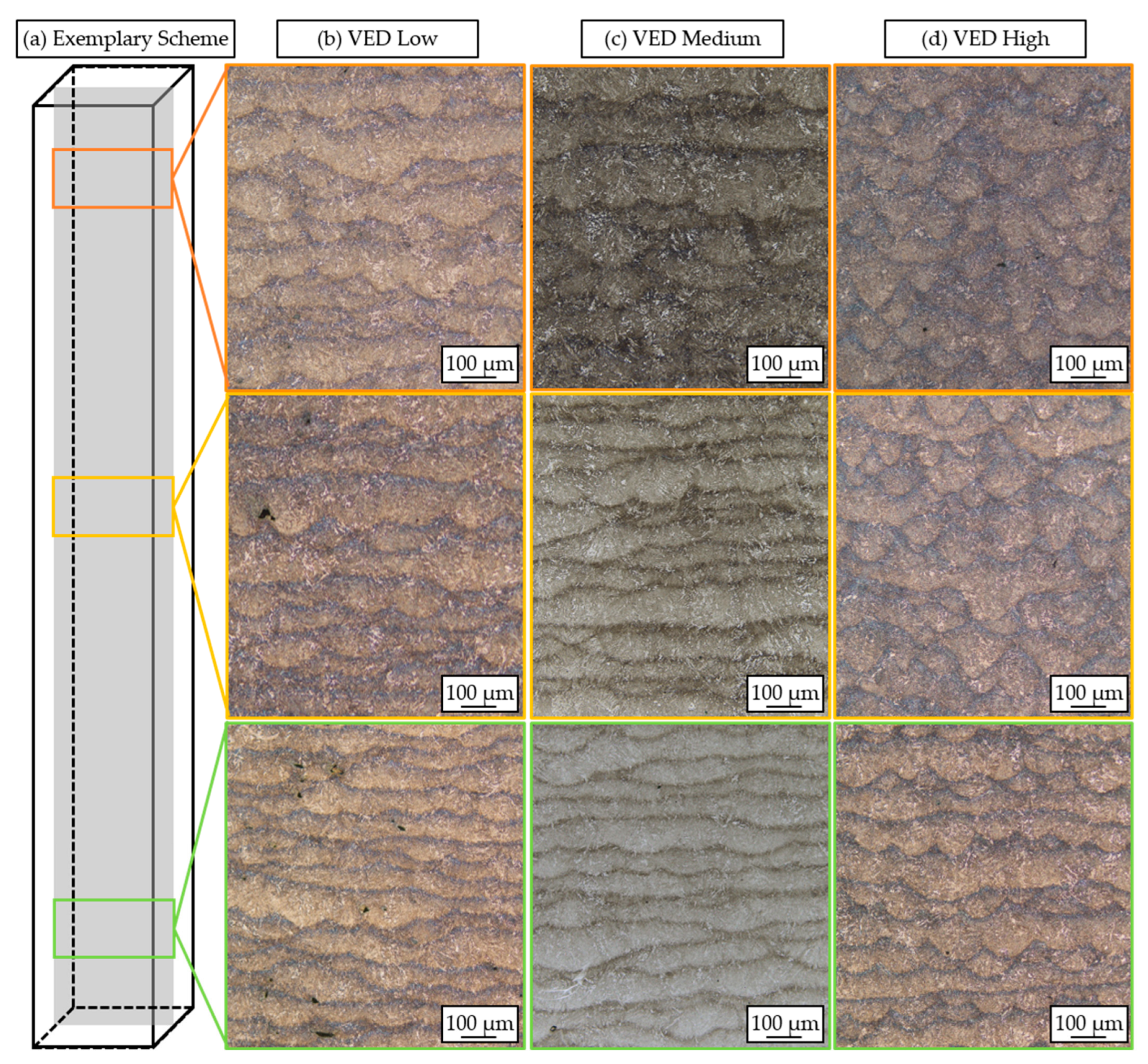
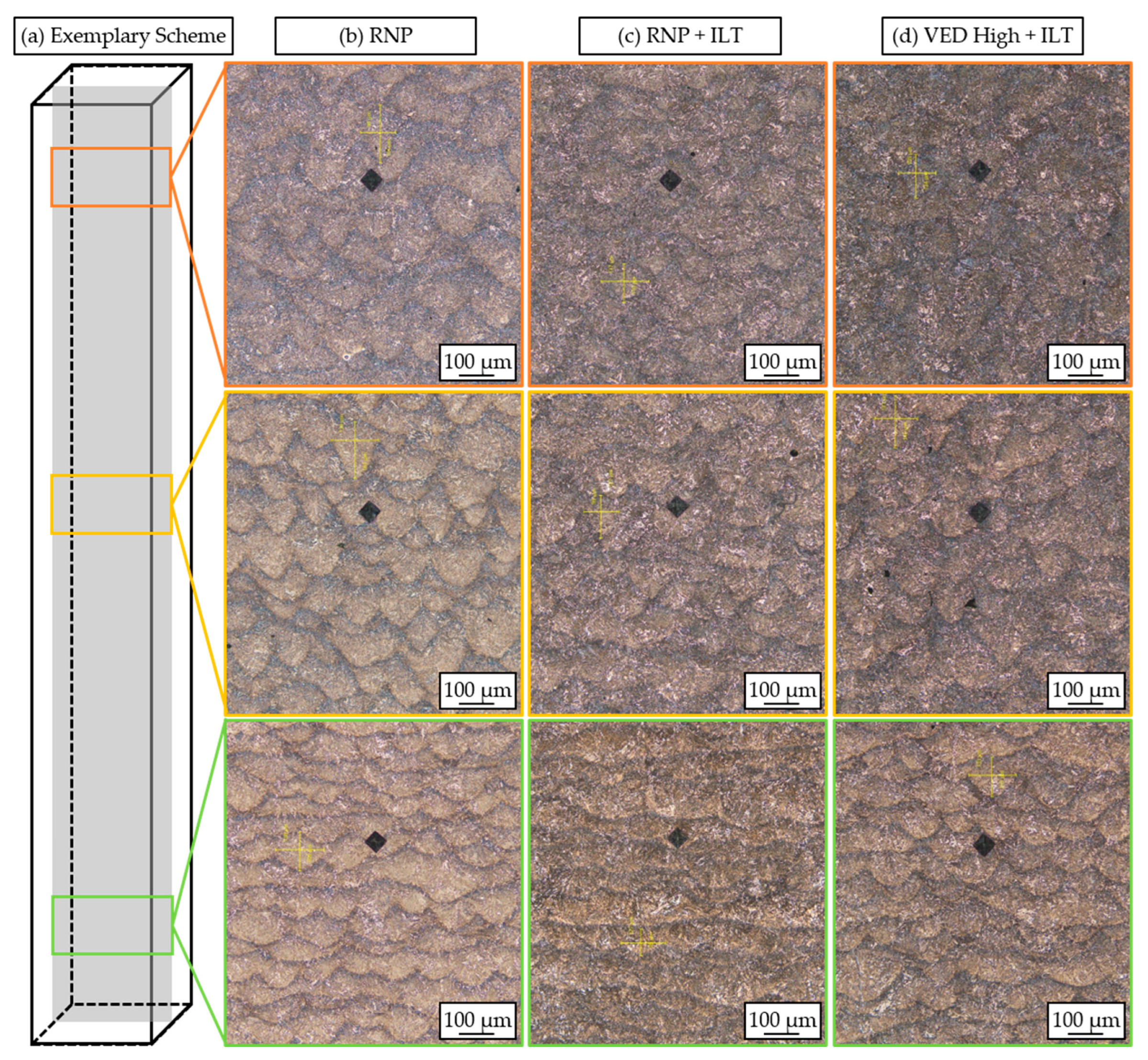
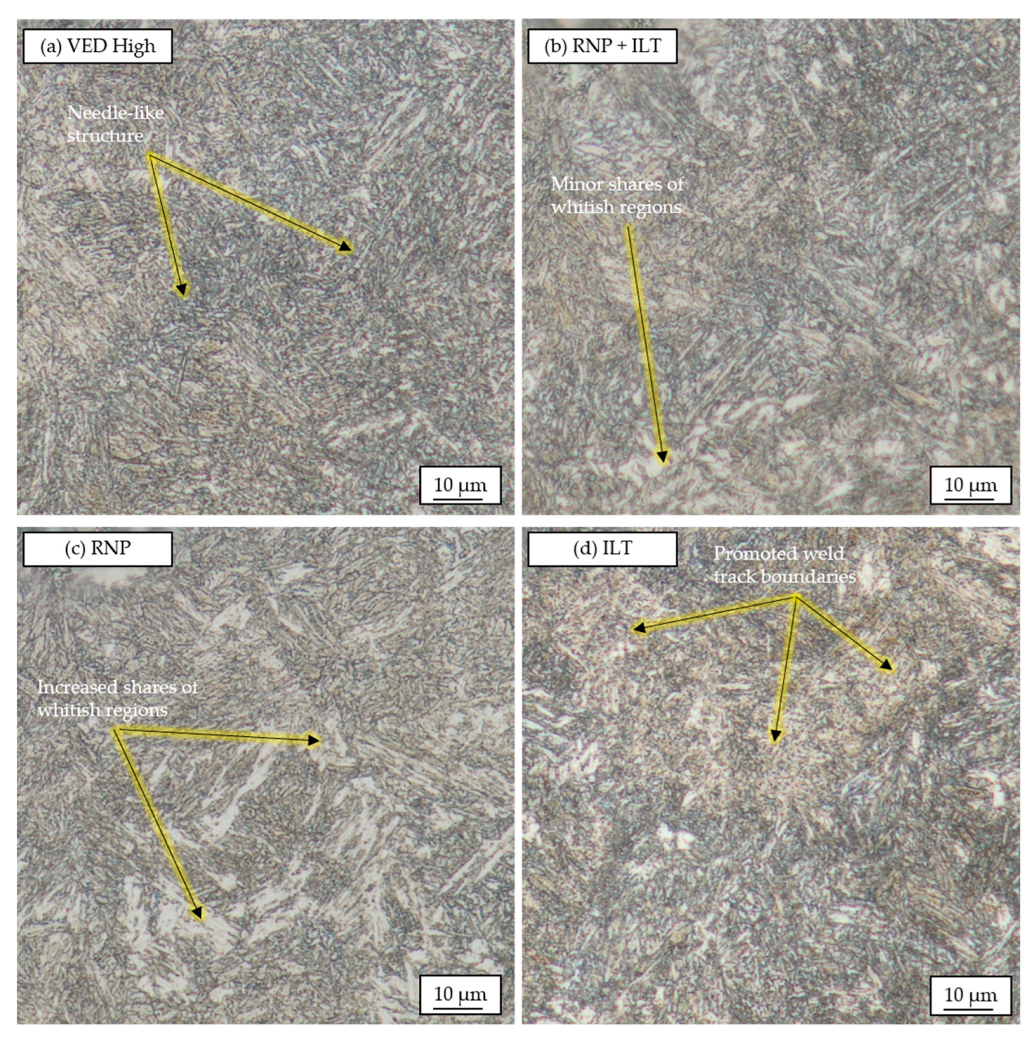
3.3. Microstructure Formation

Similarly to the relative part density, the development of the microstructure was analyzed for the different process conditions. Thereby, a distinction into overview images of several weld tracks and magnifications of a region that only consists of few single tracks was made. Figure 7 shows optical overview images of the etched cross-sections for the three different VEDs. These cross-sections were analyzed in three different regions of the specimen, as indicated in Figure 7a. For the lowest VED, lack-of-fusion pores can be identified within the bottom region of the specimen. These defects are characterized by their aspheric shape and can be predominantly found at the lower boundaries of the weld tracks within the additively manufactured structure. Their presence reduces with an increasing part height. Here, an influence of the heat accumulation along the build direction is assumed. This correlates with the weld track geometry, which is also affected by the applied VEDs. In the bottom region, the entire weld tracks appears like a longish block. Moving towards higher regions, the typical lenticular shape of the weld tracks starts to form. The increased penetration depth is associated with a reduced material hardness, as shown in Figure 6a. This supports the assumption that the reduced hardness is caused by the heat accumulation and the lower cooling rates along the build direction during PBF-LB/M. Furthermore, the weld track boundaries possess a blueish color. This can be an indicator for ferrite, which correlates with previous findings that were obtained for the case-hardening steel Bainidur AM [16].
Increasing the VED results in a larger penetration depth into the lower layers of the weld track already in the bottom regions. As for VED Low, this effect is further promoted when moving towards higher regions within the specimen. Here, the weld track depth increases with increasing part height. The heat accumulation during PBF results in an in situ preheating. These elevated temperatures result in larger melt pools, as can be seen for the different VEDs. Since this effect is thermally driven, the influence of the different PBF-LB/M-specific boundary conditions on the formation of the weld tracks was studied. Figure 8 presents the cross-section of the specimens RNP, RNP + ILT, and ILT.
Reducing the number of parts (Figure 8b) results in a larger penetration depth in the bottom region compared to the specimens that were manufactured in a build job with more parts (Figure 7d). As for the different VEDs, it can be seen that the weld track geometry is altered when moving towards higher regions within the specimen. This effect is observed independent of the applied countering strategy.
This effect is damped when adding an additional inter-layer time while still manufacturing the same amount of parts (Figure 8c). The added time (2.8 s) provides more time for the heat to dissipate. Even though this time is very short, a difference in the penetration depth of the weld tracks can be observed. Consequently, the average size of the weld tracks reduces. This effect is also seen when manufacturing five samples with an additional inter-layer time that is equal to five specimens. However, this inter-layer time appears too high, as increased defect formation can be determined for this parameter set. It is therefore recommended to avoid excessive inter-layer times when lower energy inputs, which might only be just sufficient for melting the powder material, are chosen. To better assess the microstructure, even larger magnifications of the underlying weld tracks and their corresponding microstructures were generated. Figure 9 shows the microstructure of the specimens manufactured with VED High and the three different countering strategies.
Parameter combination VED High is characterized by a fine and needle-like structure (Figure 9a). This structure appears to be like a martensitic one. When reducing the number of specimens within the build job, an increased amount of whitish blocks can be observed within the samples (Figure 9c). This is an indicator for retained austenite, which correlates well with the reduced material hardness for these specimens. When increasing the dwell time between two layers (Figure 9b), the amount of these whitish blocks decreases. Increasing the inter-layer time even further leads to an almost complete absence of these whitish regions within the geometry. The longer dwell times support a better heat dissipation, which again leads to lower average layer temperatures. This helps to achieve a more homogeneous transformation of the martensite upon cooling. Furthermore, the weld track boundaries are more pronounced for longer inter-layer times. A similar effect was also shown in Figure 8.
Overall, the appearance of the microstructure is affected by the different processing strategies. Slight changes can be identified when modifying the processing strategy through the addition of, e.g., inter-layer times or by reducing the number of parts within one build job. This shows the sensitivity of the final material properties of low-alloyed steels when processed by means of laser-based additive manufacturing.

4. Conclusions

This work shows the influence of different volumetric energy densities (VEDs) on key material properties like microstructure, weld track geometry, and material hardness. Since a correlation between the applied VED and the resulting properties that can be associated with a process-intrinsic overheating could be observed, additional countering strategies were investigated. These include prolonged inter-layer time and a modified number of parts per build job. The main findings of this work are as follows:
  • The applied VED strongly affects the material properties as higher energy inputs result in overheating. Associated with this overheating are increased weld penetration depths and hardness drop-offs.
  • By modifying the applied VED, the severity of this effect can be reduced, even though it cannot be avoided completely.
  • While low VEDs almost completely avoid the hardness drop-off, lack-of-fusion defects make this parameter combination unsuited for the fabrication of loaded products.
  • The inter-layer time between two consecutive layers was identified to be the most critical influencing factor to avoid or force an overheating of the specimens.
  • Increasing the inter-layer time can help in reducing overheating effects. This, however, might be associated with undesired material properties (e.g., brittle martensitic phases due to higher cooling gradients) and prolonged manufacturing times. The characterization of these properties will be scope of future work using experimental techniques like X-ray diffraction.
  • The minimal VED should not fall below 25 J/mm3 to avoid lack-of-fusion defects during build-up.
  • Adding moderate inter-layer times that are equivalent to a few specimens (≈20% of the build job time) helps in homogenizing the material properties by suppressing or at least postponing overheating effects.
It is recommended to use low VEDs for the fabrication of larger structures. However, the VEDs should be sufficiently high to avoid lack-of-fusion porosity. Future work could focus on the influence of different processing strategies on the material properties within specific part regions. This could include the continuous lowering of the VED or the spatial adjustment of the material properties to generate discontinuous material properties.

Author Contributions

D.B.: Conceptualization, Methodology, Validation, Investigation, Writing—original draft preparation, Visualization; M.E.A.: Investigation, Validation; F.N.: Writing—review and editing, Methodology; M.S.: Writing—review and editing, Supervision, Project administration, Funding acquisition, Resources. All authors have read and agreed to the published version of the manuscript.

Funding

This research was funded by the German Research Foundation (DFG) for Project-ID 61375930, SFB 814—“Additive Manufacturing” TP A05.

Data Availability Statement

Raw data and material are available upon reasonable request.

Acknowledgments

The authors want to thank the German Research Foundation (DFG) for Project-ID 61375930–SFB 814—“Additive Manufacturing” TP A05. We acknowledge financial support provided by Deutsche Forschungsgemeinschaft and Friedrich-Alexander-Universität Erlangen-Nürnberg within the funding program “Open Access Publication Funding”. The authors gratefully acknowledge the support provided by the Erlangen Graduate School in Advanced Optical Technologies. We would also like to thank Deutsche Edelstahlwerke Specialty Steel GmbH for their respective support within this work.

Conflicts of Interest

The authors declare no conflict of interest.

References

  1. Grosch, J.; Bartz, W.J. Einsatzhärten: Grundlagen–Verfahren–Anwendung–Eigenschaften einsatzgehärteter Gefüge und Bauteile; Kontakt & Studiumv. 356; Expert: Tübingen, Germany, 2019. [Google Scholar]
  2. Sharma, R.C. Principles of Heat Treatment of Steels; New Age International: New Delhi, India, 1996. [Google Scholar]
  3. Rakhit, A.K. Heat Treatment of Gears—A Practical Guide for Engineers; ASM International: Materials Park, OH, USA, 2010. [Google Scholar]
  4. Kamps, T. Leichtbau von Stirnzahnrädern aus Einsatzstahl mittels Laserstrahlschmelzen. Ph.D. Thesis, Technische Universität München, München, Germany, 2018. [Google Scholar]
  5. Emmelmann, C.; Sander, P.; Kranz, J.; Wycisk, E. Laser Additive Manufacturing and Bionics: Redefining Lightweight Design. Phys. Procedia 2011, 12, 364–368. [Google Scholar] [CrossRef]
  6. Elliott, A.M.; Waters, C. Additive Manufacturing for Designers—A Primer; SAE International: Warrendale, PA, USA, 2019. [Google Scholar] [CrossRef]
  7. Todd, M.K. High Value Manufacturing: Advanced Research in Virtual and Rapid Prototyping. In Proceedings of the 6th International Conference on Advanced Research in Virtual and Rapid Prototyping, Leiria, Portugal, 1–5 October 2013; CRC Press: Boca Raton, FL, USA, 2013. [Google Scholar]
  8. Bartels, D.; Klaffki, J.; Pitz, I.; Merklein, C.; Kostrewa, F.; Schmidt, M. Investigation on the Case-Hardening Behavior of Additively Manufactured 16MnCr5. Metals 2020, 10, 536. [Google Scholar] [CrossRef]
  9. Yang, M.; Sisson, R.D. Carburizing Heat Treatment of Selective-Laser-Melted 20MnCr5 Steel. J. Mater. Eng. Perform. 2020, 29, 3476–3485. [Google Scholar] [CrossRef]
  10. Schmitt, M.; Schlick, G.; Seidel, C.; Reinhart, G. Examination of the processability of 16MnCr5 by means of laser powder bed fusion. Procedia CIRP 2018, 74, 76–81. [Google Scholar] [CrossRef]
  11. Schmitt, M.; Gerstl, F.; Boesele, M.; Horn, M.; Schlick, G.; Schilp, J.; Reinhart, G. Influence of Part Geometry and Feature Size on the Resulting Microstructure and Mechanical Properties of the Case Hardening Steel 16MnCr5 processed by Laser Powder Bed Fusion. Procedia CIRP 2021, 104, 726–731. [Google Scholar] [CrossRef]
  12. Schmitt, M.; Kempter, B.; Inayathulla, S.; Gottwalt, A.; Horn, M.; Binder, M.; Winkler, J.; Schlick, G.; Tobie, T.; Stahl, K.; et al. Influence of Baseplate Heating and Shielding Gas on Distortion, Mechanical and Case hardening Properties of 16MnCr5 fabricated by Laser Powder Bed Fusion. Procedia CIRP 2020, 93, 581–586. [Google Scholar] [CrossRef]
  13. Aumayr, C.; Platl, J.; Zunko, H.; Turk, C. Additive Manufacturing of a Low-alloyed Engineering Steel. BHM 2020, 165, 137–142. [Google Scholar] [CrossRef]
  14. Schmitt, M.; Gottwalt, A.; Winkler, J.; Tobie, T.; Schlick, G.; Stahl, K.; Tetzlaff, U.; Schilp, J.; Reinhart, G. Carbon Particle In-Situ Alloying of the Case-Hardening Steel 16MnCr5 in Laser Powder Bed Fusion. Metals 2021, 11, 896. [Google Scholar] [CrossRef]
  15. Bartels, D.; Novotny, T.; Hentschel, O.; Huber, F.; Mys, R.; Merklein, C.; Schmidt, M. In situ modification of case-hardening steel 16MnCr5 by C and WC addition by means of powder bed fusion with laser beam of metals (PBF-LB/M). Int. J. Adv. Manuf. Technol. 2022, 120, 1729–1745. [Google Scholar] [CrossRef]
  16. Bartels, D.; Novotny, T.; Mohr, A.; van Soest, F.; Hentschel, O.; Merklein, C.; Schmidt, M. PBF-LB/M of Low-Alloyed Steels: Bainite-like Microstructures despite High Cooling Rates. Materials 2022, 15, 6171. [Google Scholar] [CrossRef]
  17. Huber, F.; Rasch, M.; Schmidt, M. Laser Powder Bed Fusion (PBF-LB/M) Process Strategies for In-Situ Alloy Formation with High-Melting Elements. Metals 2021, 11, 336. [Google Scholar] [CrossRef]
  18. Zhang, B.; Li, Y.; Bai, Q. Defect Formation Mechanisms in Selective Laser Melting: A Review. Chin. J. Mech. Eng. 2017, 30, 515–527. [Google Scholar] [CrossRef]
  19. Kumar, P.; Farah, J.; Akram, J.; Teng, C.; Ginn, J.; Misra, M. Influence of laser processing parameters on porosity in Inconel 718 during additive manufacturing. Int. J. Adv. Manuf. Technol. 2019, 103, 1497–1507. [Google Scholar] [CrossRef]
  20. Cacace, S.; Semeraro, Q. On the Lack of fusion porosity in L-PBF processes. Procedia CIRP 2022, 112, 352–357. [Google Scholar] [CrossRef]
  21. Moussaoui, K.; Rubio, W.; Mousseigne, M.; Sultan, T.; Rezai, F. Effects of Selective Laser Melting additive manufacturing parameters of Inconel 718 on porosity, microstructure and mechanical properties. Mater. Sci. Eng. A 2018, 735, 182–190. [Google Scholar] [CrossRef]
  22. de Terris, T.; Andreau, O.; Peyre, P.; Adamski, F.; Koutiri, I.; Gorny, C.; Dupuy, C. Optimization and comparison of porosity rate measurement methods of Selective Laser Melted metallic parts. Addit. Manuf. 2019, 28, 802–813. [Google Scholar] [CrossRef]
  23. Mohr, G.; Altenburg, S.J.; Hilgenberg, K. Effects of inter layer time and build height on resulting properties of 316L stainless steel processed by laser powder bed fusion. Addit. Manuf. 2020, 32, 101080. [Google Scholar] [CrossRef]
  24. Mohr, G.; Sommer, K.; Knobloch, T.; Altenburg, S.J.; Recknagel, S.; Bettge, D.; Hilgenberg, K. Process Induced Preheating in Laser Powder Bed Fusion Monitored by Thermography and Its Influence on the Microstructure of 316L Stainless Steel Parts. Metals 2021, 11, 1063. [Google Scholar] [CrossRef]
  25. Keshavarzkermani, A.; Marzbanrad, E.; Esmaeilizadeh, R.; Mahmoodkhani, Y.; Ali, U.; Enrique, P.D.; Zhou, N.Y.; Bonakdar, A.; Toyserkani, E. An investigation into the effect of process parameters on melt pool geometry, cell spacing, and grain refinement during laser powder bed fusion. Opt. Laser Technol. 2019, 116, 83–91. [Google Scholar] [CrossRef]
  26. Tang, M.; Pistorius, P.C.; Narra, S.P.; Beuth, J.L. Rapid Solidification: Selective Laser Melting of AlSi10Mg. JOM 2016, 68, 960–966. [Google Scholar] [CrossRef]
  27. Song, B.; Dong, S.; Deng, S.; Liao, H.; Coddet, C. Microstructure and tensile properties of iron parts fabricated by selective laser melting. Opt. Laser Technol. 2014, 56, 451–460. [Google Scholar] [CrossRef]
  28. Rasch, M.; Bartels, D.; Sun, S.; Schmidt, M. AlSi10Mg in Powder Bed Fusion with Laser Beam: An Old and Boring Material? Materials 2022, 15, 5651. [Google Scholar] [CrossRef] [PubMed]
  29. Montevecchi, F.; Venturini, G.; Grossi, N.; Scippa, A.; Campatelli, G. Idle time selection for wire-arc additive manufacturing: A finite element-based technique. Addit. Manuf. 2018, 21, 479–486. [Google Scholar] [CrossRef]
  30. Denlinger, E.R.; Heigel, J.C.; Michaleris, P.; Palmer, T. Effect of inter-layer dwell time on distortion and residual stress in additive manufacturing of titanium and nickel alloys. J. Mater. Process. Technol. 2015, 215, 123–131. [Google Scholar] [CrossRef]
  31. Spierings, A.B.; Dawson, K.; Uggowitzer, P.J.; Wegener, K. Influence of SLM scan-speed on microstructure, precipitation of Al3Sc particles and mechanical properties in Sc- and Zr-modified Al-Mg alloys. Mater. Des. 2018, 140, 134–143. [Google Scholar] [CrossRef]
  32. Lee, H.; Jung, J.E.; Kang, D.-S.; Jeong, H.W.; Yun, D.W.; Choe, J.; Yoo, Y.S.; Seo, S.-M. Oxide dispersion strengthened IN718 owing to powder reuse in selective laser melting. Mater. Sci. Eng. A 2022, 832, 142369. [Google Scholar] [CrossRef]
  33. Wang, M.; Li, W.; Wu, Y.; Li, S.; Cai, C.; Wen, S.; Wei, Q.; Shi, Y.; Ye, F.; Chen, Z. High-Temperature Properties and Microstructural Stability of the AISI H13 Hot-Work Tool Steel Processed by Selective Laser Melting. Met. Mater. Trans. B 2019, 50, 531–542. [Google Scholar] [CrossRef]
  34. Hooper, P.A. Melt pool temperature and cooling rates in laser powder bed fusion. Addit. Manuf. 2018, 22, 548–559. [Google Scholar] [CrossRef]
  35. Pauly, S.; Wang, P.; Kühn, U.; Kosiba, K. Experimental determination of cooling rates in selectively laser-melted eutectic Al-33Cu. Addit. Manuf. 2018, 22, 753–757. [Google Scholar] [CrossRef]
Figure 1. (a) Morphology of the Bainidur AM particles, (b) its particle size distribution, (c) the AconityMINI machine used for the experiments, and (d) the build chamber with the reduced build envelope.
Alloys 02 00013 g001
Figure 2. Methodological approach for the investigations within this work.
Alloys 02 00013 g002
Figure 3. (a) Build job design, (b) sample preparation, (c) regions for determining the relative part density, and (d) scheme for hardness measurements.
Alloys 02 00013 g003
Figure 4. Cross-sections of the specimens manufactured with the different VEDs. The images were extracted from three different regions along build direction.
Alloys 02 00013 g004
Figure 5. Cross-sections of the specimens manufactured with different countering strategies to avoid the intrinsic overheating. The specimens were extracted from three different regions along the build direction.
Alloys 02 00013 g005
Figure 6. Material hardness of the specimens manufactured with (a) different VEDs and (b) different countering strategies.
Alloys 02 00013 g006
Figure 7. Etched cross-sections of the specimens manufactured with different VEDs.
Alloys 02 00013 g007
Figure 8. Etched cross-sections of the specimens manufactured with different countering strategies.
Alloys 02 00013 g008
Figure 9. Magnified cross-sections of the specimens manufactured using different countering strategies.
Alloys 02 00013 g009
Table 1. Elemental composition of the Bainidur AM powder material according to the supplier’s certificate.
Element Concentration in wt.-%
CSiMnPSCrMoNiVFe
0.220.71.2<0.02<0.021.00.9<0.3<0.15Bal.
Table 2. Process parameters selected for the fabrication of the specimens.
ParameterVED LowVED MediumVED High
Laser Power [W]175 W200 W250 W
Scanning Speed [mm/s]950 mm/s850 mm/s700 mm/s
Hatch Distance [µm]120 µm120 µm110 µm
Avg. Time per Layer [s]19.6 s20.2 s20.9 s
VED [J/mm3]25.6 J/mm332.7 J/mm354.1 J/mm3
Disclaimer/Publisher’s Note: The statements, opinions and data contained in all publications are solely those of the individual author(s) and contributor(s) and not of MDPI and/or the editor(s). MDPI and/or the editor(s) disclaim responsibility for any injury to people or property resulting from any ideas, methods, instructions or products referred to in the content.

