Article

Fretting Corrosion Performance Evaluation of Uncoated Cladding, Cr Coating Cladding and AlCrNbSiTi Coating Cladding

Reactor Material Corrosion and Protection Laboratory, Institute of Reactor Engineering and Technology, China Institute of Atomic Energy, Beijing 102413, China
*
Author to whom correspondence should be addressed.
Submission received: 31 August 2023 / Revised: 18 September 2023 / Accepted: 21 September 2023 / Published: 28 September 2023
(This article belongs to the Special Issue New Alloys for Surface Engineered Coatings, Interfaces and Films)

Abstract

:
In pressurized water reactors (PWRs), flow-induced vibration (FIV) induces the fretting wear of fuel rods and supporting grids, and the process is accompanied by corrosion, which is called fretting corrosion. In this paper, fretting corrosion experiments were carried out in a simulated cladding service environment, and the fretting corrosion performance of AlCrNbSiTi coating cladding, Cr coating cladding and uncoated cladding with the supporting grids were investigated using a three-dimensional white light interferometer and a scanning electron microscope (SEM). The results showed that the AlCrNbSiTi coating cladding has the strongest fretting corrosion performance, the Cr coating cladding has the second best fretting corrosion performance and the uncoated cladding has the worst fretting corrosion performance. The coating also changes the wear mechanism of the cladding and improves the corrosion resistance of the cladding, which is responsible for the improvement in the fretting corrosion performance of the cladding. By comparing the AlCrNbSiTi coating with the Cr coating, it was found that the AlCrNbSiTi coating has a better fretting corrosion performance than the Cr coating due to its higher hardness and stronger corrosion resistance.

1. Introduction

Zirconium alloys have been selected as claddings for UO2 fuel since 1950 due to their good oxidation resistance, excellent resistance to neutron irradiation, good ductility and low thermal neutron absorption cross-section. In the process of nuclear reactor operation, the gaps between the zirconium alloy claddings and the supporting grids are generated, and when the gaps are large enough, under the action of flow-induced vibration (FIV), there is a relative sliding displacement between the claddings and the supporting grids, so that the fretting wear occurs, and, at the same time, this process is accompanied by corrosion, known as fretting corrosion [1], which will cause serious damage to the zirconium alloy cladding [2,3].
The 2011 Fukushima nuclear accident demonstrated that zirconium alloys react strongly with water at high temperatures to produce large amounts of hydrogen, which has a significant safety risk of hydrogen explosion and seriously threatens the safety of the reactor [4,5]. Since then, the safety performance of nuclear fuel under extreme accident conditions has received much attention, and the concept of accident-tolerant fuel (ATF) cladding has been proposed with the aims of improving the oxidation resistance of the cladding, reducing the temperature rise and hydrogen release and prolonging the response time in case of accidents [6]. At present, the major international nuclear materials research institutes, such as the United States Westinghouse (WHE), France Farmaton (CEA), Korea Atomic Energy Authority (KAERI), China Nuclear Power Research, Design Institute (NPIC), etc., have carried out a lot of research work [7,8,9,10], and have formed their own advantages of the ATF cladding development technical route. Their main research findings include the research and development of various new ATF cladding materials, including FeCrAl cladding and SiC cladding [11,12], and the exploration of the technology involved in producing ATF cladding coatings on the surface of zirconium alloy cladding, such as Cr coatings [8], MAX-phase coatings [13], high-entropy alloy coatings and other coatings [14], which have received extensive attention and research investigations; in addition, the selection of coating processes is based on their respective technical advantages, such as arc ion plating, magnetron sputtering, laser cladding and physical vapor deposition [7,8,9,10], which have all previously been applied.
The research work carried out in this paper is on the evaluation of the performance of ATF coating cladding, and, therefore, the common ATF coating cladding is described in detail. In the current research on various types of coatings, Cr has become the most promising ATF coating material by virtue of its easy-to-control compositional structure as a coating material, the relatively good match between its thermophysical properties and zirconium matrix, the similar coefficient of thermal expansion with the zirconium matrix, the good adaptability to the synergistic deformation of the film matrix that may occur in the process of service, the fact that no phase transformation occurs during its temperature rise process, and the ability to generate a dense Cr2O3 protective film on the surface after oxidation at high temperatures. In France, CEA Bischoff [15] et al. used PVD to produce the Cr coating cladding in various types of experiments and have shown good performance. Additionally, in South Korea, Kim et al. [10] carried out Cr coating cladding in the PWR’s environment corrosion experiment, and the results show that the Cr coating cladding has better corrosion resistance. Maier et al. [16] also produced Cr coating cladding using PVD, which showed strong oxidation resistance in a water vapor environment at 1300 °C. MAX-phase materials have also become one of the ATF cladding coating candidates due to their excellent high-temperature oxidation resistance, high hardness, high melting point, etc. A number of scholars have carried out comparative studies on the performance of various types of MAX-phase coating claddings, and the results show that the corrosion resistance and high-temperature oxidation resistance of different MAX-phase coating materials are not completely consistent, and the intrinsic brittleness of MAX-phase materials directly affects its ability to co-deform as a surface coating and interfilm base of a zirconium matrix, so it is difficult to carry out the practical application of them as ATF coating materials [17,18,19]. High-entropy alloy, as an emerging material with high thermal stability, good high-temperature strength and hardness, and excellent corrosion resistance and irradiation resistance, has become a development direction for researchers working on the development of ATF coating materials. This paper uses AlCrNbSiTi, which is a high-entropy alloy material; at present, less relevant research exists on high-entropy alloy coating cladding as the majority of research in this area focuses on the sole properties of high-entropy alloys. Poulia et al. [20] studied the wear resistance of MoTaWNbV refractory high entropy alloy using the ball and disk abrasion method, and the results showed that it has very strong wear resistance. Additionally, Kumar et al. [21] compared the anti-irradiation properties of Fe27Ni28Mn27Cr18-HEA and conventional austenitic steels, such as FeNiCr and FeMnCr. The results show that only Fe27Ni28Mn27Cr18-HEA exhibits high phase stability; the elemental segregation induced by irradiation at the grain boundaries is significantly suppressed and no voids are observed, collectively indicating that it has better swelling resistance.
ATF coating cladding has been developed over the years, and relevant studies have shown that the key factor in improving accident tolerance through the application of ATF coatings is to maintain the integrity of the coatings produced without significant degradation during the normal operation of the reactor [22], and, thus, it is important to ensure the integrity of the coatings during fretting corrosion. At present, some research investigations on the fretting corrosion performance of ATF cladding have been carried out in various countries. For instance, Lee et al. [23] conducted a comparative study on the fretting corrosion performance of Nano-structured Ferritic Alloy, FeCrAl, SiC, and Zr, and found that the ATF materials have extremely strong fretting corrosion resistance compared to Zr. Winter et al. [24] investigated the effect of temperature on the fretting corrosion performance of FeCrAl. They found that its fretting corrosion performance initially increases with rising temperature and then decreases after reaching 350 °C. Brachet et al. [25] evaluated the fretting corrosion performance of Cr coating Zr-4 cladding and found that there was almost no change observed in the Cr coating Zr-4 cladding during the experiment. Bischoff et al. [15] investigated the fretting corrosion performance of Cr coating M5 cladding and found that the total wear of the Cr coating cladding was reduced by two orders of magnitude compared to the uncoated cladding. Reed et al. [26] conducted fretting corrosion experiments on Cr coating ZIRLO cladding in a simulated service environment and found that the Cr coating significantly improved the fretting corrosion performance of the cladding.
In this study, a Zr–Sn–Nb alloy cladding was utilized as the matrix. AlCrNbSiTi and Cr coatings were produced using the arc ion plating deposition technology. Grid-to-rod fretting corrosion experiments were conducted using the fretting corrosion tester in a simulated primary circuit water environment of pressurized water reactors (PWRs). The three-dimensional morphology, two-dimensional contour, microscopic morphology, and element distribution of wear marks on the worn surfaces of uncoated cladding, AlCrNbSiTi coating cladding, and Cr coating cladding were analyzed and compared. Consequently, the fretting corrosion performance of the three types of cladding was evaluated, and the influence mechanism of the two coatings on the fretting corrosion behavior of the cladding was studied.

2. Materials and Methods

2.1. Experimental Materials

AlCrNbSiTi coatings were manufactured using the arc ion plating deposition technology on a single alloy target. The martix of the coating is a Zr–Sn–Nb alloy tube (12 mm × φ 9.5 mm, wall thickness 0.57 mm). Prior to the deposition, the zirconium tube was cleaned and dried. The deposition process began once the vacuum chamber was heated to 300 °C and the vacuum degree reached 6 × 10⁻⁴ Pa. The Ti target was initially connected to a DC arc power supply for ion etching cleaning in order to further clean the matrix surface and improve the coating adhesion (target current of 100 A, Ar of 0.5 Pa, bias voltage of −150 V, duty cycle of 70%, etching time of 30 min). The sample was allowed to cool in the furnace to room temperature after the deposition was completed and then removed. The process for producing the Cr coating was identical to that of AlCrNbSiTi coating. The supporting grid materials use Zr-4 plates as the friction auxiliary material.
The primary composition of the Zr–Sn–Nb alloy is shown in Table 1. The composition of the AlCrNbSiTi coating is shown in Table 2.
The hardness of the AlCrNbSiTi coating cladding, Cr coating cladding, and uncoated cladding was measured using a nanoindentation instrument. A loading force of 100 mN was applied at ten different points, and the average value was calculated. The measurement results are shown in Figure 1. The hardness of the AlCrNbSiTi coating was significantly higher than that of the other two materials. The hardness of the Cr coating sample is slightly higher than that of the uncoated clad.

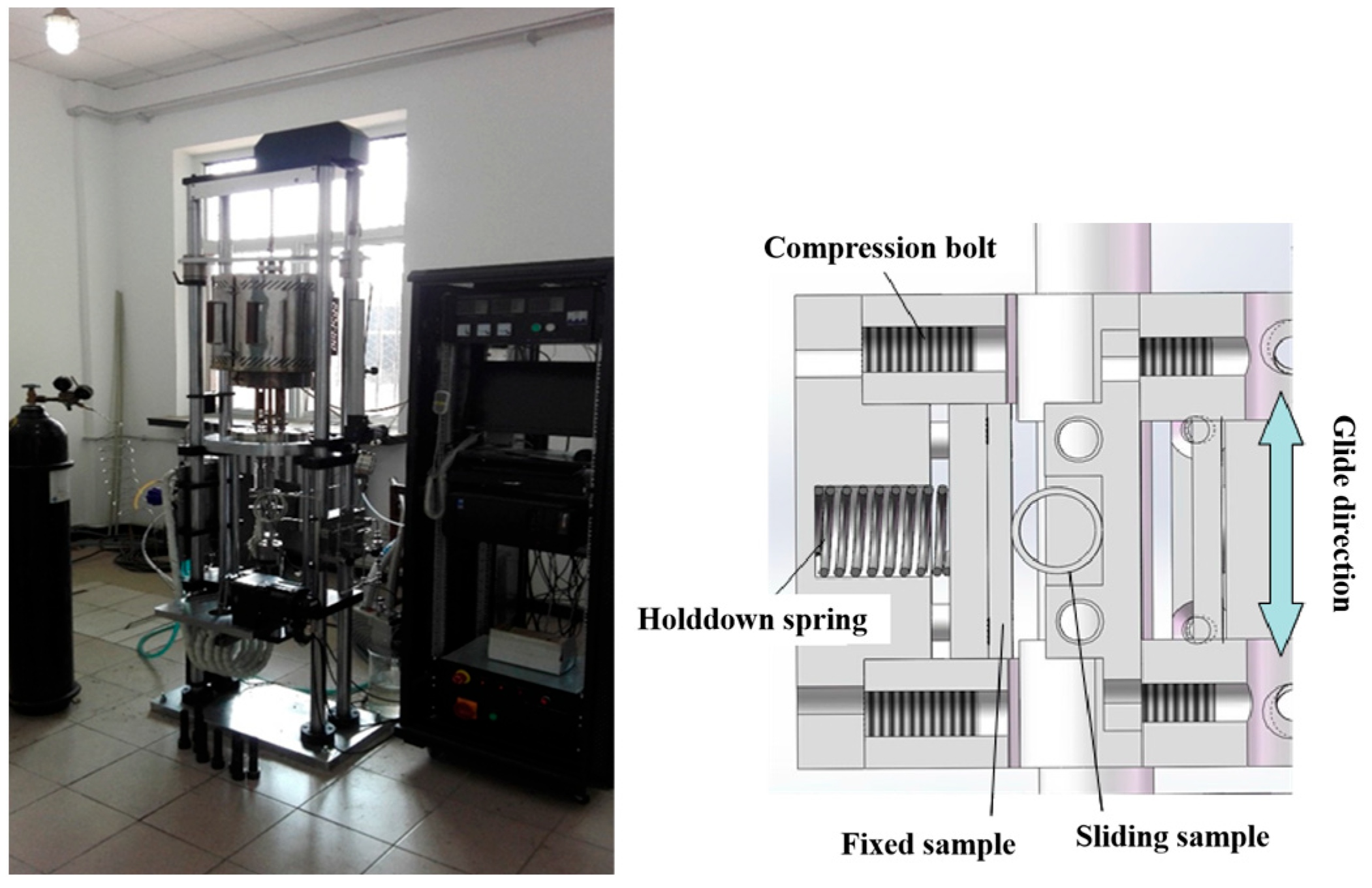
2.2. Experimental Equipment

As shown in Figure 2, the high-temperature and high-pressure fretting corrosion tester primarily consists of three parts: the autoclave and fixture inside the autoclave, the vibration generation and transmission mechanism, and the control system. The sheet and tubular samples are, respectively, held by a set of clamps and placed together inside the autoclave. The autoclave contains boron–lithium water, which is used to simulate the primary circuit water environment of the pressurized water reactor. The base where the sample fixture is located is connected to the vibration generating device through the transmission mechanism. The vibration-generating device is controlled by the computer to generate micro-vibrations of specific amplitude, and the actual slip distance is monitored by the displacement sensor in real time.

2.3. Experimental Conditions and Parameters

(1)
Temperature: 300 °C;
(2)
Pressure: 9.5 MPa;
(3)
Water chemical environment: 650 ppm B + 3.5 ppm Li;
(4)
Normal force: 10 N;
(5)
Slip distance: 100 μm;
(6)
Frequency: 20 Hz;
(7)
Time: 2 × 10⁶ times.

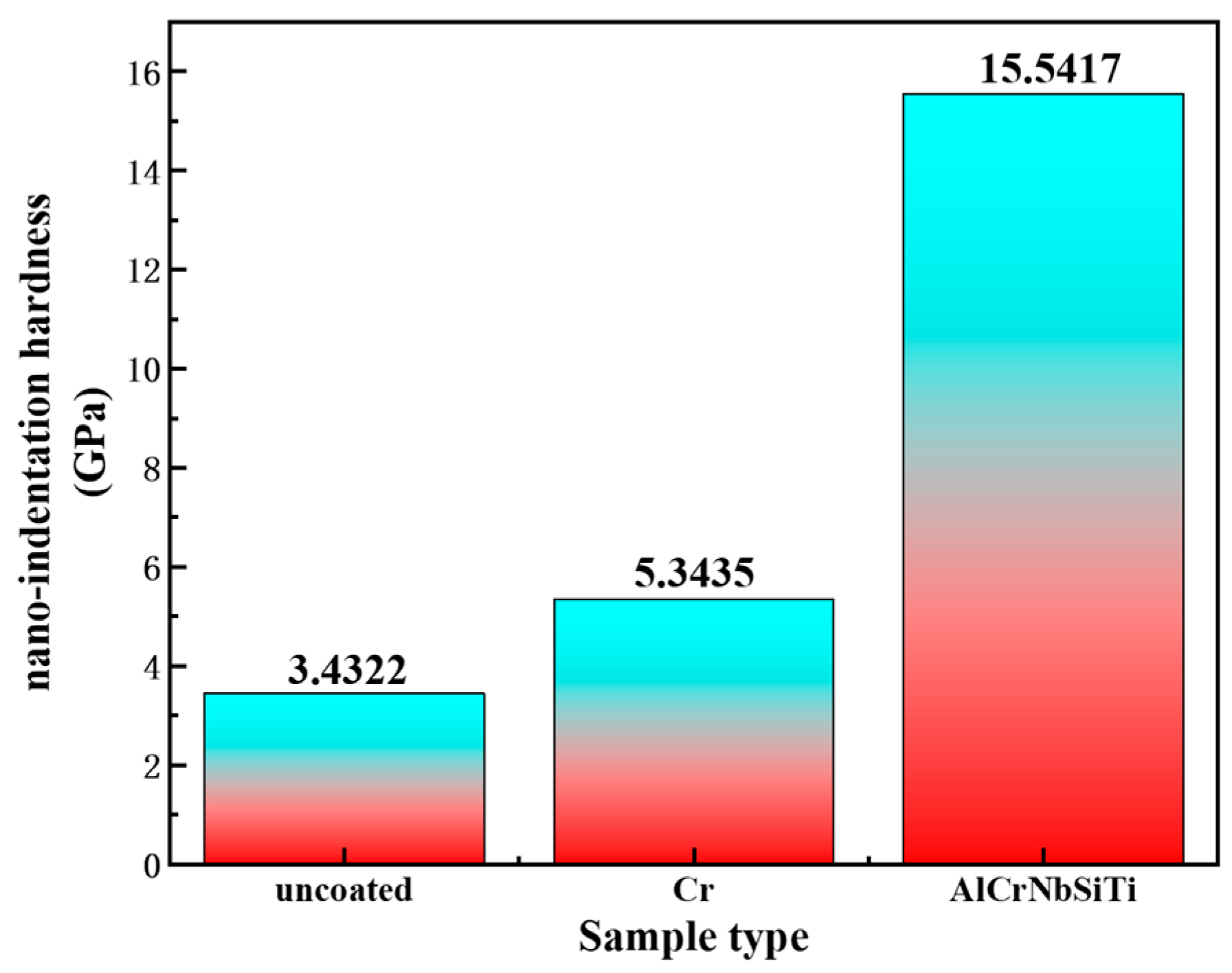
2.4. Microstructure Analysis of Experimental Samples

After completing the fretting corrosion experiments, the sample is cleaned and dried. The three-dimensional and two-dimensional contours of the sample are accurately measured using a 3D white light interferometer (Bruker ContourGT-K, New York, NY, USA). Observations are made regarding the position, shape, and distribution of wear marks, and the wear depth and volume are measured. Subsequently, a SEM (Zeiss Merlin Compact, German Zeiss, Oberkochen, Germany) is used for the meticulous observation of these wear marks, as well as the analysis of their morphology and elemental content.

2.5. Analysis and Evaluation of Fretting Corrosion Data

Wear volume is the primary index used for evaluation, according to the Archard model:
V ˙ = k W ˙
W ˙ = 1 t F d S
V ˙  denotes the volume wear rate and W ˙ denotes the work rate. k represents the wear coefficient, F denotes the normal force, S denotes the sliding distance, and t denotes the time. The wear coefficient k reflects the fretting corrosion performance of different samples, with higher values of k indicating more severe fretting corrosion under equal conditions. The wear coefficient k of different types of samples was calculated for reference.

3. Results

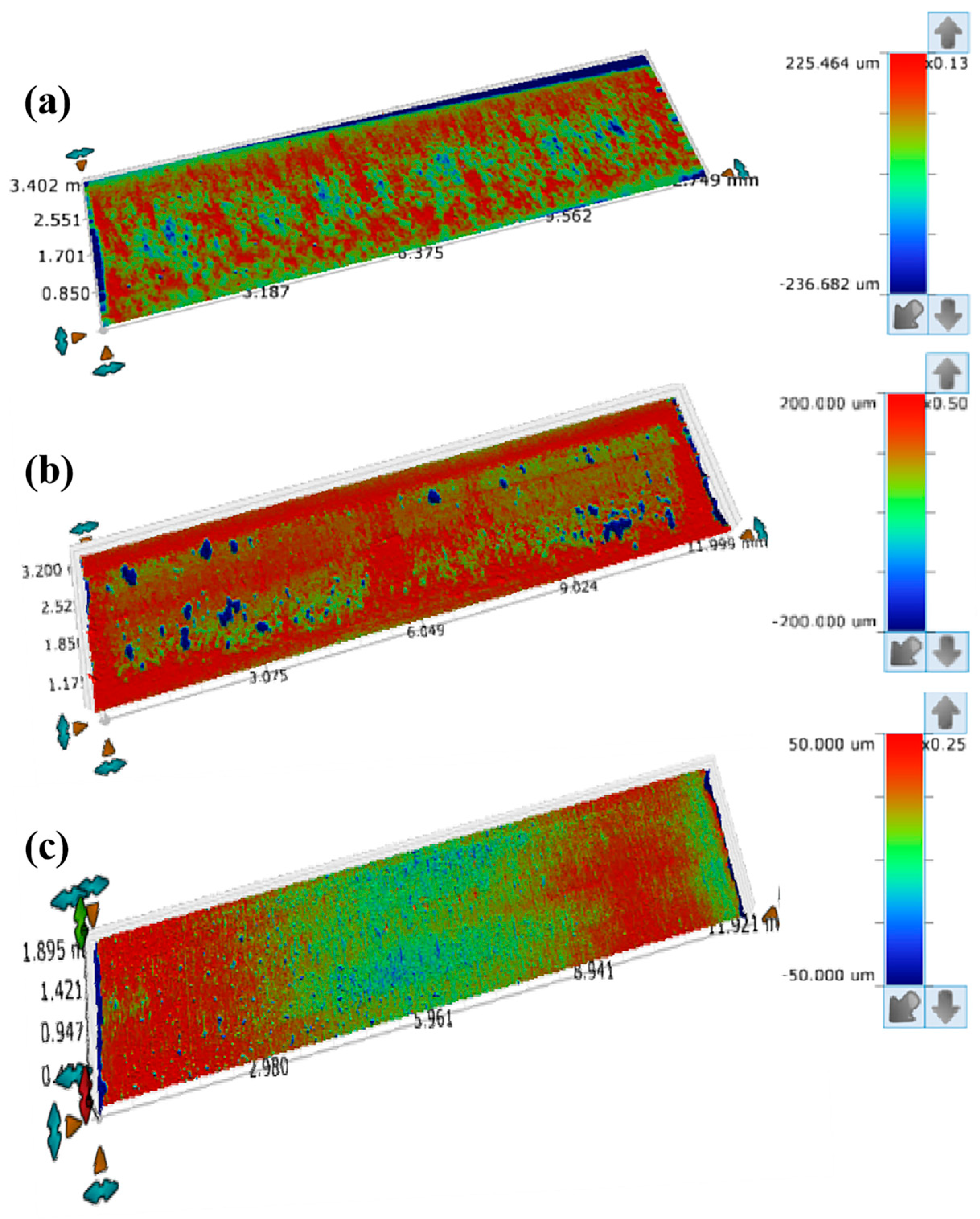
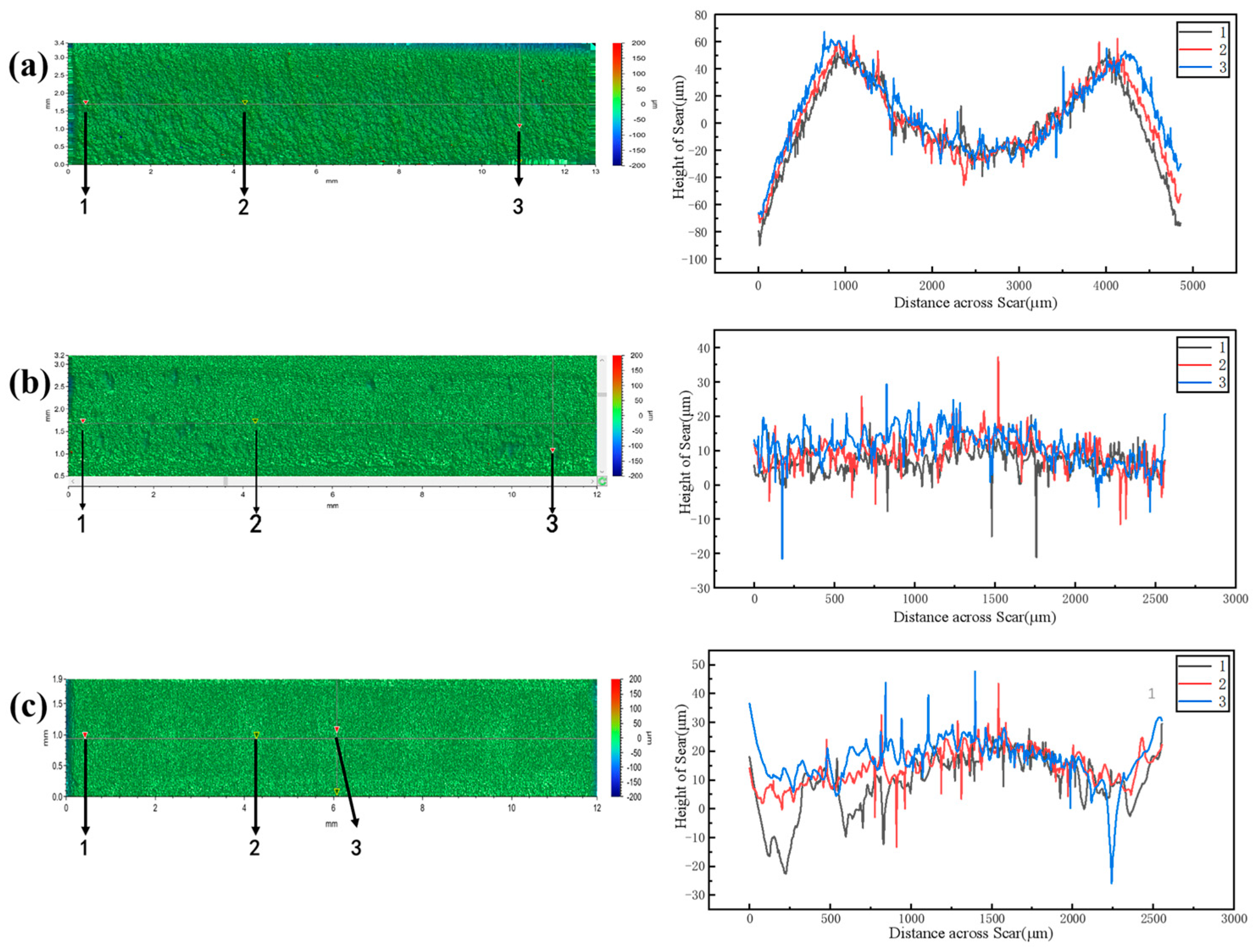
3.1. The Wear Marks Morphology and Contours

During fretting corrosion, the interaction between the cladding and the grid leads to the formation of wear marks on the cladding surface. These wear marks typically exhibit a parallel orientation to the direction of fretting, while indentations tend to appear perpendicular to the fretting direction. This particular study focuses on analyzing the wear marks present on the cladding surface. Figure 3 depicts the three-dimensional morphology of these wear marks, which was measured using a white light interferometer. Through careful observation of the 3D morphology of the wear marks and subsequent comparison and analysis of wear volume, maximum wear depth, and wear coefficient, the fretting corrosion performance of the AlCrNbSiTi coating cladding, Cr coating cladding, and uncoated cladding can be evaluated.
As illustrated in Figure 3, the overall morphology of the wear marks on the three types of cladding is essentially linear, but there is a significant variance in the extent of wear. The surface of the uncoated cladding shows severe wear, with deep wear depth and a large area of deep wear, leading to extensive material loss. The surface of the Cr coating cladding has less wear, and although the wear depth is relatively large, the deep wear area is minimal and scattered around the edges of the wear marks. This is speculated to be a result of coating delamination, resulting in relatively small material loss. The surface wear on the AlCrNbSiTi coating cladding is the least, with a lower wear depth. There is only a slightly deeper area in the center of the wear scar, and the deepest depth of wear is approximately 50 μm, there is virtually no loss of material. Figure 4 shows the 2D contours of wear marks on different types of cladding surfaces. According to reference [27], the portion below the original reference surface of the friction pair is the material loss or wear volume, and the portion above the original surface is the material transfer. From the cross-sectional profile curves of the wear marks on the uncoated cladding, it is evident that there was material loss on the cladding surface. In contrast, the AlCrNbSiTi coating cladding and the Cr coating cladding exhibit virtually no material loss but show a small amount of material transfer. This transfer is due to the adhesion of some friction auxiliary materials on the surfaces of the two types of coating claddings. Upon comparing the cross-sectional profile curves of the three types of claddings, it is evident that the uncoated cladding has a larger wear mark width, roughly twice that of the coating claddings. Its profile curve is an “M” shape, with large abrasion pits in the center of the wear mark, indicating severe wear. Both types of coating claddings have smaller and nearly identical wear mark widths, and their contour curves are gentler, indicating that the wear on the coating claddings is lighter.
The wear volume of three types of cladding was analyzed using the volume analysis module of a white light interferometer, and the wear coefficients of the three types of cladding were calculated based on the Archard equation [28,29,30]. Table 3 displays the calculation results. The table clearly shows that the wear volume and wear coefficient of the uncoated cladding are significantly higher than those of the two types of coating cladding, suggesting poor fretting corrosion performance. The wear volume and wear coefficient of the Cr coating cladding are slightly higher than those of the AlCrNbSiTi coating cladding, and its fretting corrosion performance is good. The wear volume and wear coefficient of the AlCrNbSiTi coating cladding are smaller, demonstrating the strongest fretting corrosion performance.

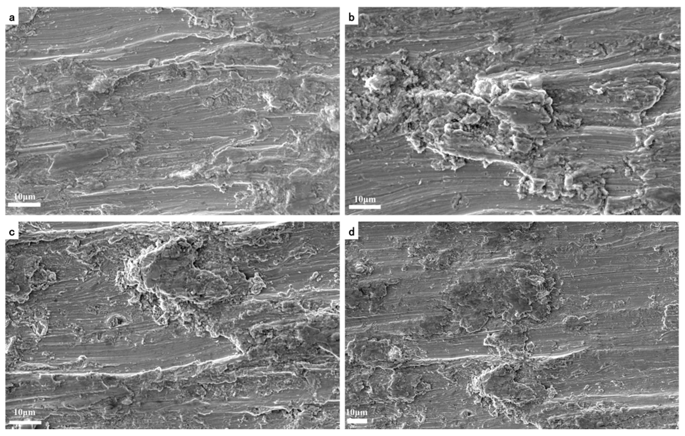
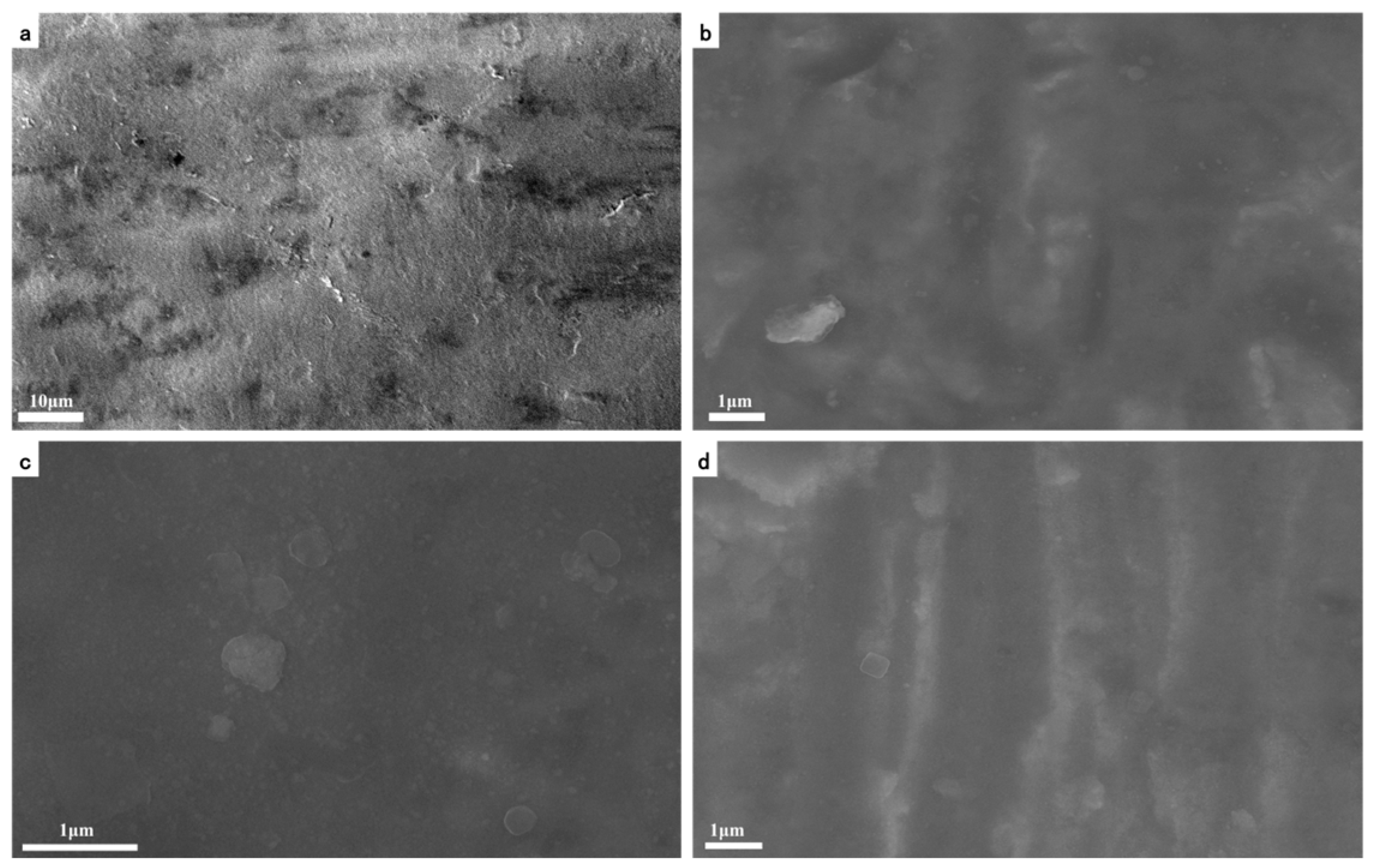
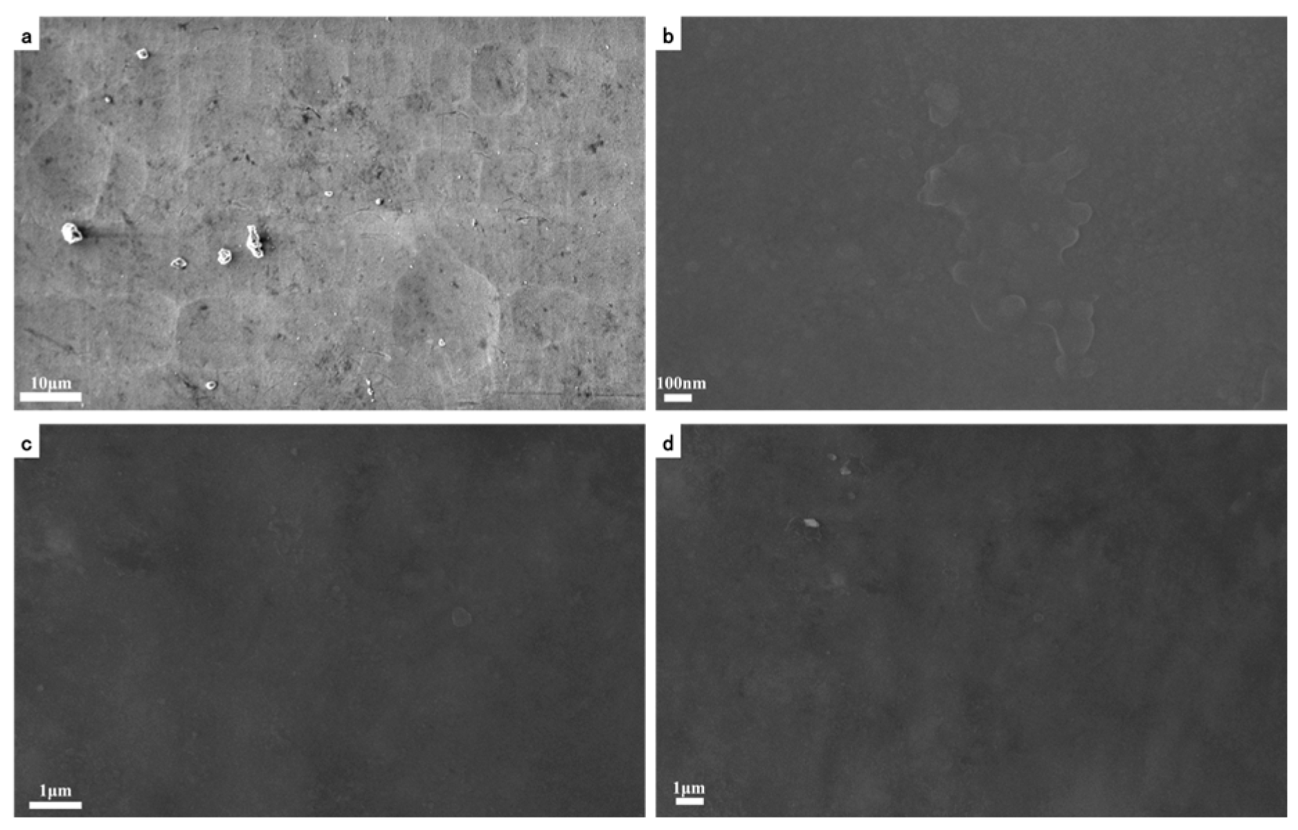
3.2. Microscopic Damage Mechanisms

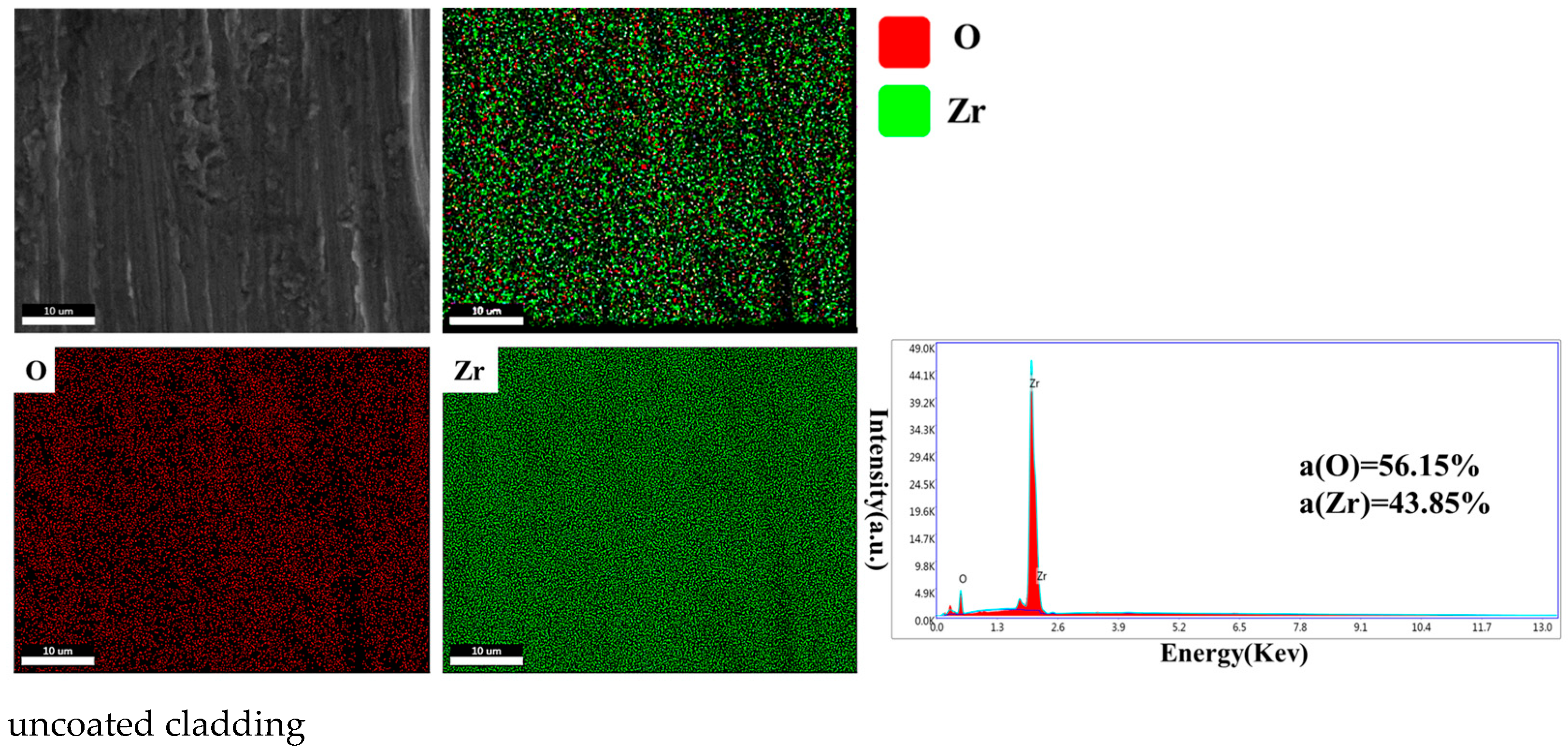
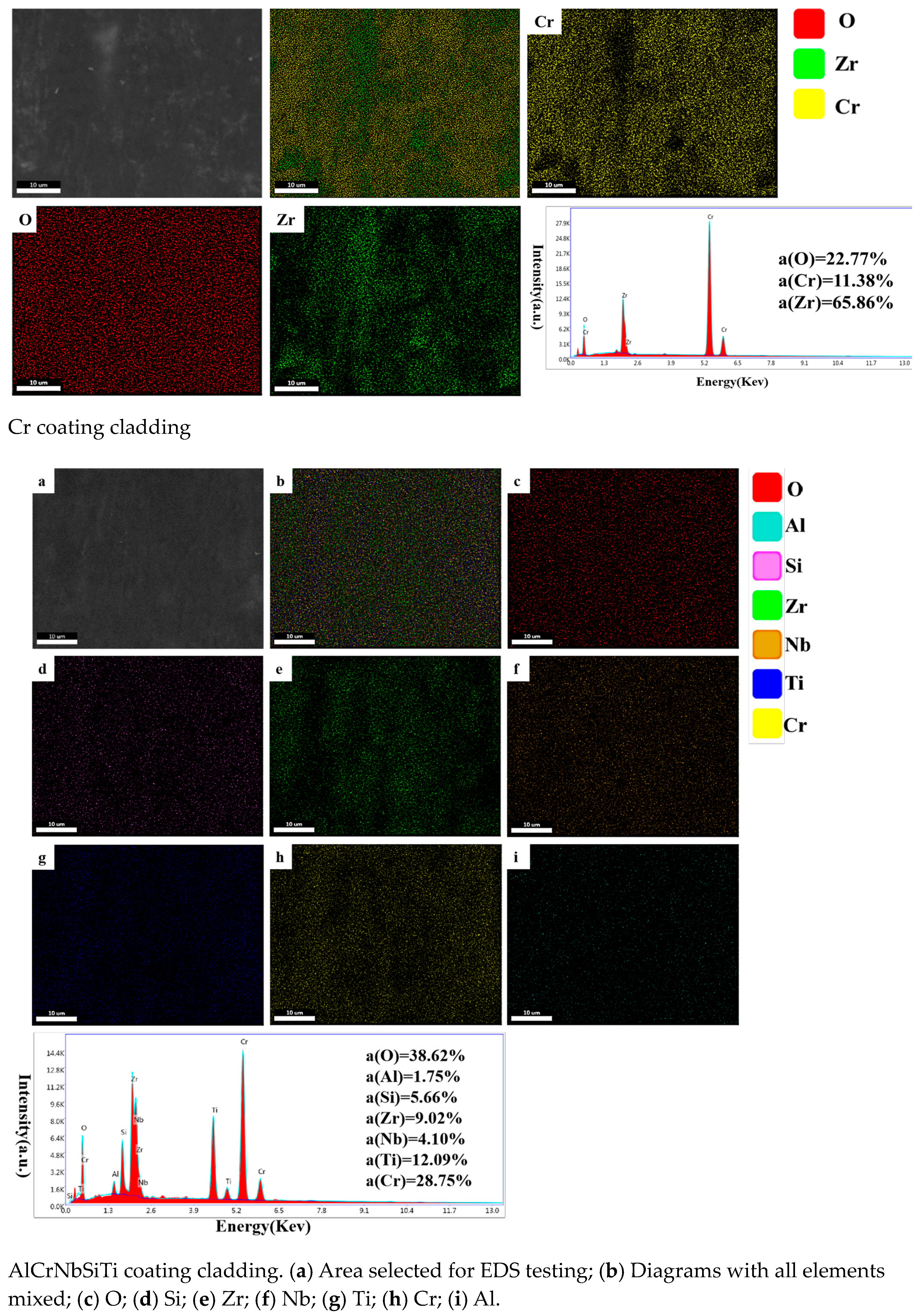
3.2.1. Surface Morphology and Elemental Distribution of Wear Marks

Figure 5 shows the SEM diagram of the wear surface morphology for the uncoated cladding. The surface exhibits numerous grooves and plow groove traces that are parallel to the fretting direction, along with a significant amount of finely crushed and agglomerated abrasive debris, as well as a small number of block particles. These harder abrasive particles act as abrasive particles in the reciprocating motion between the contact surfaces of the friction pair, gradually producing a plowing effect on the surface of the cladding. The wear marks on the uncoated cladding surface exhibit typical abrasive wear. At the same time, there is a significant amount of tear damage on the surface of the sample, indicating that adhesive wear during the experiment is more severe. Therefore, the wear mechanism of the uncoated cladding mainly involves adhesive wear and abrasive wear.
Figure 6 presents the SEM diagram of the surface morphology of the worn area of the Cr coating cladding. The sample surface displays slight damage, and the worn surface appears to be covered with a thin layer of debris. This is a result of material transfer from the friction pair to the cladding during the fretting corrosion. Upon magnification, an extremely small number of particles and very slight scratches are observed on the sample surface. The SEM experimental results suggest that the wear mechanism of the Cr coating cladding involves unidirectional material transfer and slight abrasive wear.
Figure 7 depicts the SEM diagram of the surface morphology of the AlCrNbSiTi coating cladding wear area. The sample surface shows minimal damage, with a small amount of granular abrasive debris and extremely fine scratches visible on the surface of the wear mark. These abrasions were caused by the material transfer from the friction pair to the cladding during the fretting corrosion. Further magnification reveals a small amount of extremely tiny particles on the sample surface, but virtually no scratches. Therefore, the SEM results demonstrate that the wear mechanism of the AlCrNbSiTi coating cladding involves only a very small amount of unidirectional material transfer.
EDS surface scanning was used to analyze the element distribution in the wear areas of the uncoated, Cr coating, and AlCrNbSiTi coating cladding surfaces, and to simultaneously analyze and compare the corrosion degrees of the three types of cladding. As shown in Figure 8, a comparison of the oxygen content on the surface of the three types of cladding reveals oxidation on all three types under the simulated conditions of a pressurized water reactor primary circuit. However, the degree of oxidation varies, with the uncoated cladding experiencing the most severe oxidation, followed by the AlCrNbSiTi coating cladding, and the Cr coating cladding displaying the least oxidation. Oxygen forms a protective oxide layer on the surface of both types of coating cladding, which, together with the coating, provides complete protection for the cladding. In contrast, although oxygen generates a protective layer of zirconia on the surface of the uncoated cladding, its protective ability is less effective than that of the two types of coating samples, resulting in greater wear on the uncoated cladding. At the same time, it is observed that both coating samples have Zr elements on the surface, suggesting material transfer during the experimental process. The Cr coating surface has a higher content of Zr elements, with a large amount of Zr transferred from the Zr-4 friction pair material to the Cr coating cladding during the experiment. In contrast, the AlCrNbSiTi coating sample has a lower content of Zr elements, indicating a small amount of Zr transferred from the Zr-4 friction pair material to the AlCrNbSiTi coating cladding during the experiment.

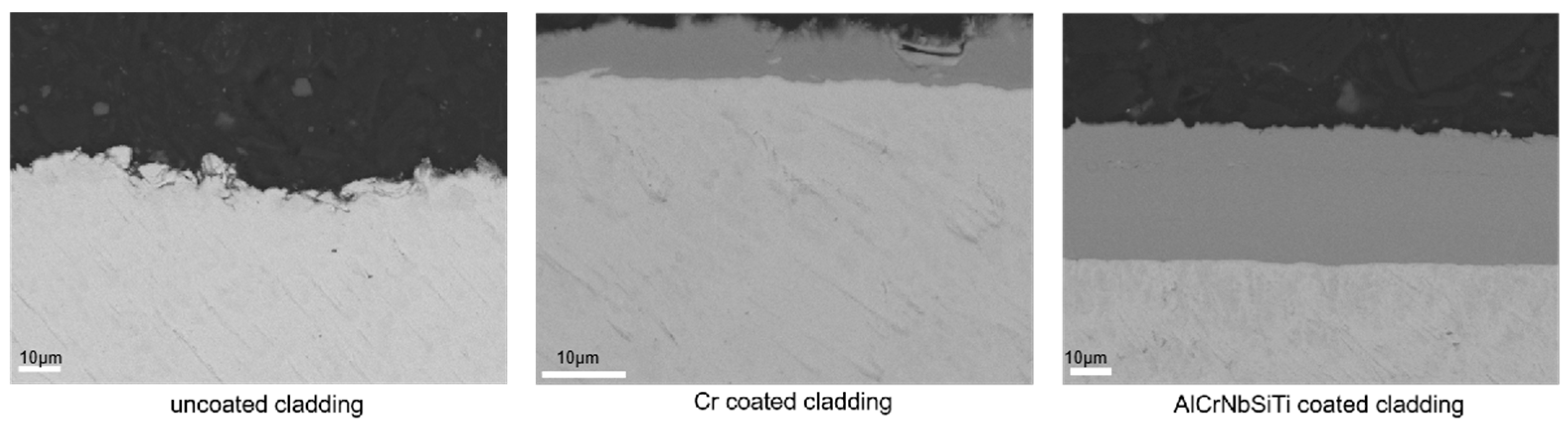
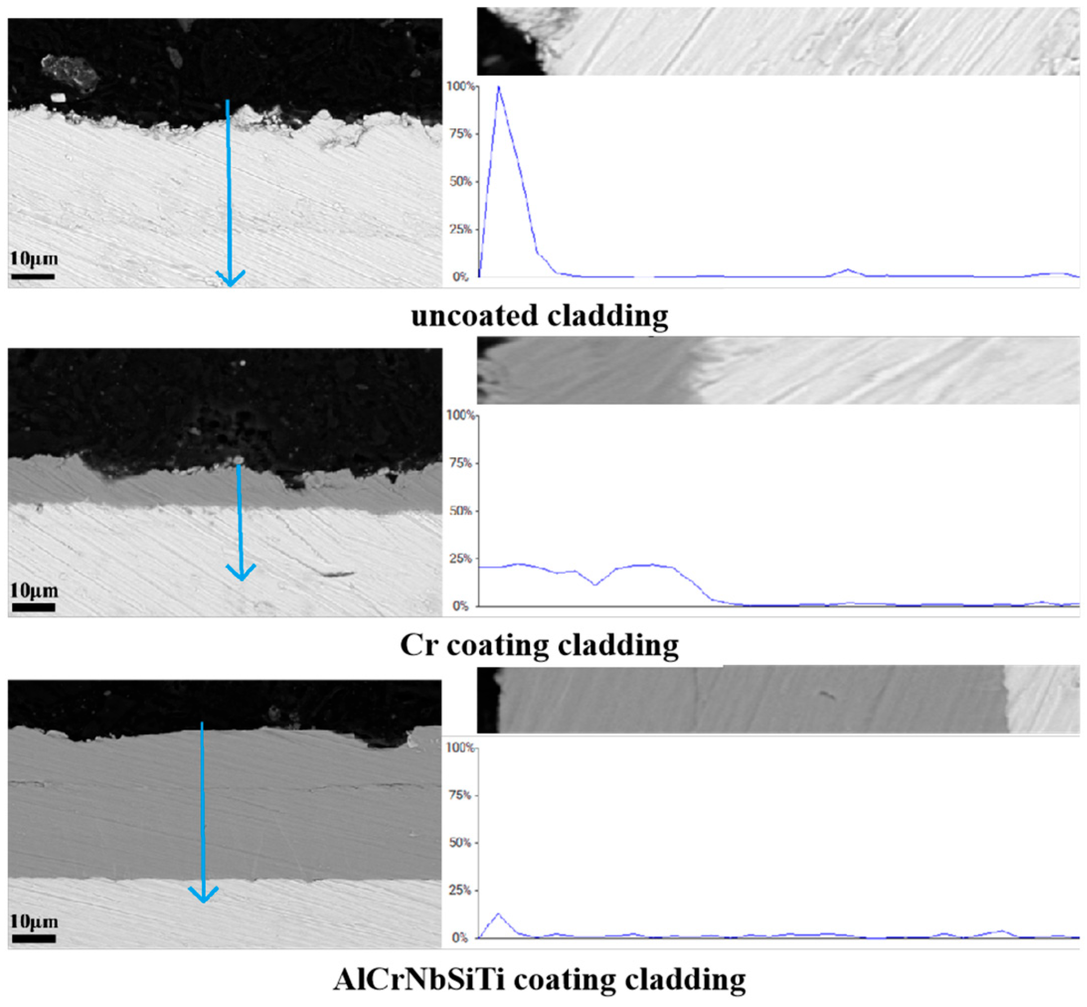
3.2.2. Cross-Sectional Morphology and Elemental Distribution of Wear Marks
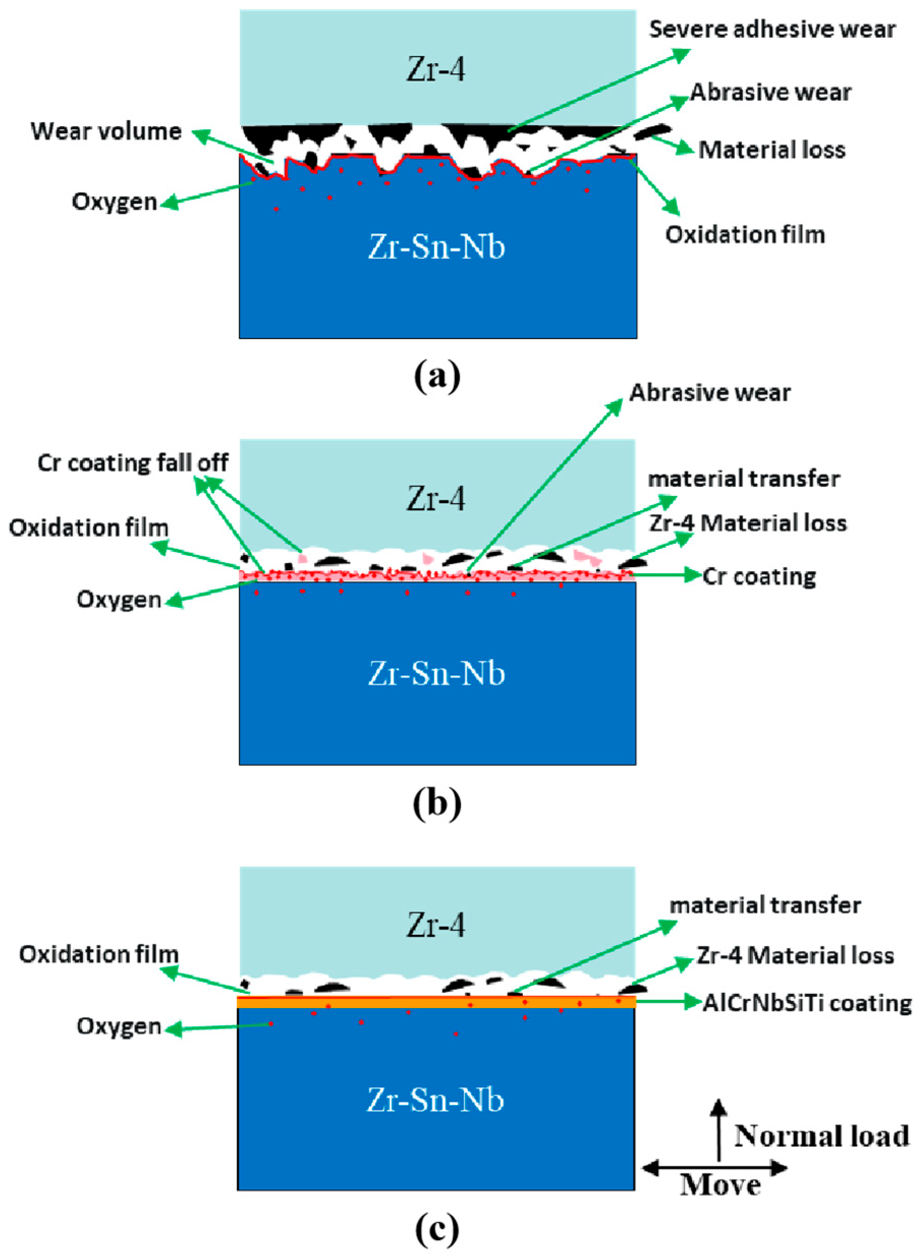
As shown in Figure 9, the SEM diagram for the cross-sectional morphology of the wear area for the three types of cladding shows severe wear and substantial material loss on the uncoated cladding surface. The Cr coating cladding surface also displays significant damage, but the coating remains intact, providing effective protection for the matrix material. The AlCrNbSiTi coating cladding samples exhibit only extremely minimal damage on the surface, suggesting excellent protection for the matrix material. The difference between the two coating cladding samples is attributed to the hardness of the two coatings, with the AlCrNbSiTi coating cladding displaying superior fretting corrosion performance during the experiment due to its considerably higher hardness compared to the Cr coating cladding.
The oxygen distribution in the cross-sections of the uncoated, Cr coating, and AlCrNbSiTi coating cladding sections is analyzed using EDS, as shown in Figure 10. It shows that, under simulated conditions of a pressurized water reactor primary circuit, all three types of cladding experienced some degree of oxidation. The most severe oxidation occurred in the cross-sections of the uncoated cladding samples, with a significant amount of the surface oxidation layer detaching. The cross-sectional oxidation of the Cr coating cladding samples is relatively serious, with a higher degree of oxidation present in the Cr coating than in the base material. The distribution of oxygen across the sample is uniform. The AlCrNbSiTi coating samples have the least cross-sectional oxidation, with only the sample surface oxidized. The experimental results show that both coatings improve the corrosion resistance of the cladding compared to the uncoated cladding. However, the AlCrNbSiTi coating exhibits superior corrosion resistance. Oxidation only occurs on the surface of the coating, with almost no oxygen diffusing into the coating interior, resulting in minimal coating detachment. Conversely, the Cr coating, being slightly less corrosion-resistant, shows almost complete oxidation, which led to some coating detachment. However, the zirconium alloy matrix was not exposed, indicating that the Cr coating still provides protection.

4. Discussion

According to the above research and analysis, the fretting corrosion mechanism of the three types of cladding was analyzed. Figure 11a provides a schematic diagram of the fretting corrosion mechanism between the uncoated cladding and the supporting grid. The abrasion tear-like damage on the surface of the uncoated cladding (seen in Figure 5) suggests that severe adhesive wear occurs between the uncoated cladding and the supporting grid. The plow groove traces on the surface of the uncoated cladding (also seen in Figure 5) suggest that the cladding also experiences abrasive wear due to the action of abrasive debris. The wear volume test results in Table 3 show that the uncoated cladding has the greatest material loss. The uncoated cladding sample’s EDS analysis results (shown in Figure 8 and Figure 10) reveal that the uncoated cladding has poor corrosion resistance, experiences severe oxidation, and loses a large amount of oxide film. This leads to the conclusion that the uncoated cladding has inferior fretting corrosion performance.
Figure 11b shows a schematic of the fretting corrosion mechanism between the Cr coating cladding and the supporting grid. Figure 4b and Figure 6, as well as the EDS analysis results of the Cr coating cladding sample in Figure 8, illustrate the occurrence of severe unidirectional material transfer from the supporting grid to the Cr coating cladding during the experiment. The scratches on the wear mark surface in Figure 6d demonstrate a small amount of abrasive wear during the experiment. The wear volume test results in Table 3 show a lower material loss in the Cr coating cladding, but higher than that of the AlCrNbSiTi coating cladding. The improved fretting corrosion performance of the Cr coating cladding compared to the uncoated cladding can be attributed to several factors. The presence of the Cr coating alters the wear mechanism between the cladding and the supporting grid. This alteration completely avoids adhesive wear and reduces abrasive wear due to the Cr coating’s strong bond to the matrix and its high hardness. Further, the EDS analysis results of the Cr coating cladding sample, shown in Figure 8 and Figure 10, reveal that the Cr coating provides a certain degree of corrosion resistance. This protective layer prevents the zirconium alloy matrix from corroding. However, the Cr coating itself undergoes serious oxidation. Observations during the experimental process indicated that parts of the Cr coating cladding partially detached, but the material matrix was not exposed. This detachment is speculated to be related to the oxidation of the Cr coating, which increases its brittleness, leading to partial detachment during the experimental process. Despite this, the Cr coating cladding still demonstrated strong fretting corrosion performance.
Figure 11c shows a schematic diagram of the fretting corrosion mechanism between the AlCrNbSiTi coating cladding and the supporting grid. As shown in Figure 4c, and in the EDS analysis results of the AlCrNbSiTi coating cladding samples in Figure 8, there is only a slight unidirectional transfer of material from the supporting grid to the AlCrNbSiTi coating cladding during the experiment. The results in Figure 7 and Figure 9 reveal virtually damage-free sample surfaces. The AlCrNbSiTi coating’s improved fretting corrosion performance, similar to that of the Cr coating, is due to several factors. Firstly, it completely prevents adhesive wear between the cladding and the supporting grid because of its superior bonding with the matrix. Secondly, the hardness of the AlCrNbSiTi coating is significantly higher than that of the Cr coating, which enables it to avoid abrasive wear entirely. The wear volume test results in Table 3 demonstrate that AlCrNbSiTi coating cladding has the strongest fretting wear performance among the three types of cladding, with extremely low material loss. The EDS analysis results of the AlCrNbSiTi coating cladding sample, shown in Figure 8 and Figure 10, indicate that, although the surface oxidation of the AlCrNbSiTi coating is more severe, it plays a crucial role in preventing the diffusion of oxygen to the inside of the coating. Only a very small amount of oxygen elements diffused to the inside of the coating, indicating that the coating does not corrode extensively. Therefore, it can be concluded that AlCrNbSiTi coating claddings have strong fretting corrosion performance.

5. Conclusions

This paper conducted fretting corrosion experiments in a simulated service environment. The fretting corrosion performance of AlCrNbSiTi coating cladding, Cr coating cladding, and uncoated cladding was analyzed using testing measures such as a 3D white light interferometry and a SEM. The results show the following:
(1)
The AlCrNbSiTi coating cladding has the best fretting corrosion performance, the Cr coating cladding has the second best fretting corrosion performance, and the uncoated cladding has the worst fretting corrosion performance.
(2)
The AlCrNbSiTi and Cr coatings alter the wear mechanism of the cladding, preventing adhesive wear and reducing abrasive wear. Additionally, they enhanced the cladding’s corrosion resistance by restricting oxygen’s penetration into the matrix. These two factors are primary contributors to the improvement in the cladding’s fretting corrosion performance.
(3)
The fretting corrosion performance of the AlCrNbSiTi coating cladding is slightly higher than that of the Cr coating cladding, and the higher hardness of the AlCrNbSiTi coating cladding almost completely prevents abrasive wear. Additionally, the AlCrNbSiTi coating cladding reduces oxidation due to its high corrosion resistance and avoids the peeling of the coating. On the other hand, severe oxidation occurs in the Cr coating cladding, which leads to the partial detachment of the Cr coating. This difference in fretting corrosion performance between these two types of coating cladding can be attributed to this reason.
In summary, compared with the widely studied Cr coating cladding all over the world, the AlCrNbSiTi coating cladding demonstrates better performance. However, there is less related research, so we hope that it can receive more attention from researchers in the future and that its application can be realized as soon as possible in order to effectively improve the reactor accident tolerance.

Author Contributions

Writing—original draft and formal analysis, X.L.; Writing—review and editing, Y.H.; Investigation and resources, S.L.; Conceptualization and methodology, H.W.; Data curation, M.T. and B.Z.; All authors have read and agreed to the published version of the manuscript.

Funding

This research was funded by the China National Nuclear Corporation, Grant No. 197801.

Data Availability Statement

All data are presented in this manuscript.

Conflicts of Interest

The authors declare no conflict of interest.

Abbreviations

PWRspressurized water reactors
FIV flow-induced vibration
SEM scanning electron microscope
ATF accident tolerant fuel
WHE the United States Westinghouse
CEA the French Atomic Energy Commission
KAERI Korea Atomic Energy Authority
NPIC China Nuclear Power Research and Design Institute
PVD physics vapor deposition
DC direct current
3D three-dimensional
2D two-dimensional
EDS Energy Dispersive Spectrometer

References

  1. Kim, K.T.; Jang, Y.K.; Choi, J.H. A Study of Flow-Induced Grid-to-Rod Fretting Wear in PWR Fuel Assemblies. In Proceedings of the ASME/JSME 2004 Pressure Vessels and Piping Conference, San Diego, CA, USA, 25–29 July 2004. [Google Scholar]
  2. Rubiolo, P.R.; Young, M.Y. On the Factors Affecting the Fretting-Wear Risk of PWR Fuel Assemblies. Nucl. Eng. Des. 2009, 239, 68–79. [Google Scholar] [CrossRef]
  3. Pettigrew, M.J.; Carlucci, L.N.; Taylor, C.E. Flow-induced vibration and related technologies in nuclear components. Nucl. Eng. Des. 1991, 131, 81–100. [Google Scholar] [CrossRef]
  4. Tanabe, F. Fukushima NPP accident related: Analysis of core melt accident in Fukushima Daiichi-Unit 1 nuclear reactor. J. Nucl. Energy Sci. Power Gener. Technol. 2011, 48, 1135–1139. [Google Scholar]
  5. Chung, H.M. Fuelbehavior under Loss-of-Cool Antaccident Situations. Nucl. Eng. Technol. 2005, 37, 327–362. [Google Scholar]
  6. Ott, L.J.; Robb, K.R.; Wang, D.J. Preliminary assessment of accident-tolerant fuels on LWR performance during normal operation and under DB and BDB ac-cident conditions. J. Nucl. Mater. 2014, 448, 520–533. [Google Scholar] [CrossRef]
  7. Trujillo, I.I.; Flem, M.L.; Brachet, J.C. Assessment at CEA of Coated Nuclear Fuel Cladding for LWRS with Increased Margins in Loca and beyond Loca Conditions. In Proceedings of the LWR Fuel Performance Meeting/TopFuel 2013, Charlotte, NC, USA, 15–19 September 2013. [Google Scholar]
  8. Yeom, H.; Maier, B.; Johnson, G.; Dabney, T.; Lenling, M.; Sridharan, K. High Temperature Oxidation and Microstructural Evolution of Cold Spray Chromium Coatings on Zircaloy-4 in Steam Environments. J. Nucl. Mater. 2019, 526, 151737. [Google Scholar] [CrossRef]
  9. Wei, T.G.; Zhang, R.Q.; Yang, H.Y. Microstructure, Corrosion Resistance and Oxidation Behavior of Cr-Coatings on Zircaloy-4 Prepared by Vacuum Arc Plasma Deposition. Corros. Sci. 2019, 158, 108077. [Google Scholar] [CrossRef]
  10. Kim, H.G.; Kim, I.H.; Jung, Y.I. Adhesion Property and High-Temperature Oxidation Behavior of Cr-Coated Zircaloy-4 Cladding Tube Prepared by 3D Laser Coating. J. Nucl. Mater. 2015, 465, 531–539. [Google Scholar] [CrossRef]
  11. Terrani, K.A.; Zinkle, S.J.; Snead, L.L. Advanced oxidation-resistant iron-based alloys for LWR fuel cladding. J. Nucl. Mater. 2014, 448, 420–435. [Google Scholar] [CrossRef]
  12. Terrani, K.A.; Pint, B.A.; Parish, C.M. Silicon Carbide Oxidation in Steam up to 2 MPa. J. Am. Ceram.Soc. 2014, 97, 2331–2352. [Google Scholar] [CrossRef]
  13. Wen, T.L.; Zhen, L. A high oxidation resistance Ti2AlC coating on Zirlo substrates for loss-of-coolant accident conditions. Ceramurgia. Int. 2019, 4, 89. [Google Scholar]
  14. Yeom, H.; Maier, B.; Johnsom, G. Development of cold spray process for oxidation-resistant FeCrAl and Mo diffusion barrier coatings on optimized ZIRLO™. J. Nucl. Mater. 2018, 5, 14. [Google Scholar] [CrossRef]
  15. Bischoff, J.; Delafoy, C.; Vauglin, C. AREVA NP’s enhanced accident-tolerant fuel developments: Focus on Cr-coated M5 cladding. Nucl. Eng. Technol. 2018, 50, 223–228. [Google Scholar] [CrossRef]
  16. Maier, B.; Yeom, H.; Johnsom, G. Development of Cold Spray Chromium Coatings for Improved Accident Tolerant Zirconium-Alloy Cladding. J. Nucl. Mater. 2019, 519, 247–254. [Google Scholar] [CrossRef]
  17. Daub, K.; Van, N.R.; Nordin, H. Investigation of the Impact of Coatings on Corrosion and Hydrogen Uptake of Zircaloy-4. J. Nucl. Mater. 2015, 467, 260–270. [Google Scholar] [CrossRef]
  18. Alat, E.; Motta, A.T.; Comstock, R.J. Multilayer (TiN, TiAlN) Ceramic Coatings for Nuclear Fuel Cladding. J. Nucl. Mater. 2016, 478, 236–244. [Google Scholar] [CrossRef]
  19. Van, N.R.; Andersson, V.; Balak, J. In-Pile Testing of CRN, TiAlN, and AlCrN Coatings on Zircaloy Cladding in the Halden Reactor. In Proceedings of the Zirconium in the Nuclear Industry: 18th International Symposium, West Conshohocken, PA, USA, 15–19 May 2018. [Google Scholar]
  20. Poulia, A.; Georgatis, E.; Lekatou, A. Dry-sliding wear response of MoTaWNbV high entropy alloy. Adv. Eng. Mater. 2017, 19, 1600535. [Google Scholar] [CrossRef]
  21. Kumar, N.A.; Kiran, P. Microstructural stability and mechanical behavior of FeNiMnCr high entropy alloy under ion irradiation. Acta Mater. 2016, 113, 230–244. [Google Scholar] [CrossRef]
  22. Lee, Y.H.; Park, D.J.; Jung, Y.I. Impact Fretting Wear Behavior of Cr-Alloy Coating Layer for Accident-Tolerant Fuel Cladding. In Proceedings of the TMS 2022 151st Annual Meeting & Exhibition, Daejeon, Republic of Korea, 7 February 2022. [Google Scholar]
  23. Lee, Y.H.; Byun, T.S. A comparative study on the wear behaviors of cladding candidates for accident-tolerant fuel. J. Nucl. Mater. 2015, 465, 857–865. [Google Scholar] [CrossRef]
  24. Winter, T.; Thomas, N.; Richard, W.S. Coefficient of friction evolution with temperature under fretting wear for FeCrAl fuel cladding candidate. J. Nucl. Mater. 2019, 520, 140–151. [Google Scholar] [CrossRef]
  25. Tupin, M.; Brachet, J.C.; Vandenberghe, V. Early studies on Cr-Coated Zircaloy-4 as Enhanced Accident Tolerant Nuclear Fuel Claddings for Light Water Reactors. J. Nucl. Mater. 2019, 517, 268. [Google Scholar]
  26. Reed, B.; Wang, R.; Lu, R.Y. Autoclave grid-to-rod fretting wear evaluation of a candidate cladding coating for accident-tolerant fuel. Wear. 2021, 203578, 466–467. [Google Scholar] [CrossRef]
  27. Elleuch, K.; Fouvry, S. Wear analysis of A357 aluminium alloy under fretting. Wear 2002, 253, 662–672. [Google Scholar] [CrossRef]
  28. Guo, X.; Lai, P.; Tang, L. Effects of sliding amplitude and normal load on the fretting wear behavior of alloy 690 tube exposed to high temperature water. Tribol. Int. 2017, 116, 155–163. [Google Scholar] [CrossRef]
  29. Xue, X.; Wang, S.; Li, B. Modification methodology of fretting wear in involute spline. Wear 2016, 368, 435–444. [Google Scholar] [CrossRef]
  30. Ghosh, A.; Leonard, B.; Sadeghi, F. A stress based damage mechanics model to simulate fretting wear of Hertzian line contact in partial slip. Wear 2013, 307, 87–99. [Google Scholar] [CrossRef]
Figure 1. Three types of cladding nano-indentation hardness.
Alloys 02 00016 g001
Figure 2. High-temperature and high-pressure fretting corrosion tester and sample installation diagram.
Alloys 02 00016 g002
Figure 3. The 3D morphology of cladding wear marks. (a) uncoated; (b) Cr; (c) AlCrNbSiTi.
Alloys 02 00016 g003
Figure 4. The 2D contour of cladding wear marks. (a) uncoated; (b) Cr; (c) AlCrNbSiTi.
Alloys 02 00016 g004
Figure 5. Surface wear morphology of Zr–Sn–Nb cladding without coating. (a) Numerous groove and furrow marks; (b) agglomerated abrasive debris; (c,d) tear damage.
Alloys 02 00016 g005
Figure 6. Surface wear morphology of Cr coating cladding. (a) Zirconium alloy grinding chips on the Cr coating cladding surface; (b,c) abrasive particles; (d) abrasion mark.
Alloys 02 00016 g006
Figure 7. Surface wear morphology of AlCrNbSiTi coating cladding. (a,b) abrasive particles; (c,d) no scratches on the surface.
Alloys 02 00016 g007
Figure 8. Elemental distribution of wear marks on the surface of three types of cladding.
Alloys 02 00016 g008aAlloys 02 00016 g008b
Figure 9. Three types of cladding section morphology.
Alloys 02 00016 g009
Figure 10. Cross-sectional oxygen distribution for three types of cladding wear marks.
Alloys 02 00016 g010
Figure 11. Schematic diagram of the fretting corrosion mechanism of three types of cladding. (a) uncoated; (b) Cr; (c) AlCrNbSiTi.
Alloys 02 00016 g011
Table 1. Composition of the zirconium alloy matrix (wt%).
ElementZrSnNbFe
content97.830.921.130.12
Table 2. Composition of AlCrNbSiTi coating (wt%).
ElementAlCrNbSiTi
content849121219
Table 3. Clad wear volume and wear coefficient.
Sample TypeWear Volume (mm3)Wear Coefficient (Pa−1)
uncoated cladding0.2566.4 × 10−14
Cr coating cladding0.0441.1 × 10−14
AlCrNbSiTi coating cladding0.0225.5 × 10−15
Disclaimer/Publisher’s Note: The statements, opinions and data contained in all publications are solely those of the individual author(s) and contributor(s) and not of MDPI and/or the editor(s). MDPI and/or the editor(s) disclaim responsibility for any injury to people or property resulting from any ideas, methods, instructions or products referred to in the content.

