Article

Study of the Influence of Helical Milling Parameters on the Quality of Holes in the UNS R56400 Alloy

by
Francisco Javier Puerta-Morales
*,
Jorge Salguero Gomez
and
Severo Raul Fernandez-Vidal
Faculty of Engineering, Mechanical Engineering and Industrial Design Department, University of Cadiz, Av. Universidad de Cadiz 10, E-11519 Puerto Real, Cadiz, Spain
*
Author to whom correspondence should be addressed.
Submission received: 28 December 2019 / Revised: 17 January 2020 / Accepted: 22 January 2020 / Published: 24 January 2020

Abstract

:
Helical milling has been positioned as an alternative to conventional drilling, where the advantages it offers make it very attractive for use on difficult-to-machine alloys such as the titanium alloy UNS R56400. However, the correlation between the indicator of hole quality and the kinematic parameters has rarely been studied. The kinematics are what bring most advantages and that is why it is necessary to know their influence. In this aspect, there are different focuses of problems associated with the complexity of the process kinematics, which makes it necessary to undertake a deeper analysis of the process and to carry out a preliminary study. To address this problem, a DOE (Design of Experiments) is proposed to identify the sensitivity and the main trends of the properties that define the quality holes with respect to the kinematic parameters. At the same time, a nomenclature is proposed to unify and avoid misinterpretations. This study has allowed us to obtain conclusive results that offer very relevant information for future research

1. Introduction

Currently, helical milling is positioned as a good alternative to conventional drilling. In fact, the aerospace industry characterized by being at the forefront of technology seems to have found in this strategy an ally to improve the performance of drilling operations. This fact is reflected in research programs such as “Clean Sky” founded by the European Union for Horizon 2020, whose objectives include the development of innovative technologies to reduce the environmental impact of air transport and improve the sustainability of current manufacturing processes, being of great interest for this machining strategy [1,2].
In this context, the aerospace industry faces the challenge of digitizing production processes in factories using sensors and information systems to transform production processes and make them more efficient. The challenge of achieving industry 4.0 must include the added difficulty of the high qualities required of the elements and the use of difficult-to-machine material. This highlights the titanium alloy UNS R56400 commonly called Ti6Al4V, which due to its excellent relationship between mechanical properties/weight, and corrosion resistance stands out from other materials.
Many drilling techniques uses of cutting fluids to minimize the generations of typical hole defect, especially in this material. Cutting fluids have benefits such as lubrication and cooling of the machining process, reducing the coefficient of friction between the tool and the workpiece, and between the tool and the evacuated chip. In addition, they favour the evacuation of the heat in the cutting area, which contributes to removal of the generated chip and improves the tool life. However, the use of mineral-based cutting fluids, require special treatment once they have been used to eliminate the toxic component and comply with environmental legislation [3]. The use of cutting fluid can reach a cost overrun of 16% to the machining process [4]. For this reason, there is a worldline tendency to minimize or eliminate the use of traditional cutting fluid in machining operations, betting on techniques more committed to the environment. The current trend is to use dry or near-dry machining techniques for green manufacturing [5,6,7].
The use of helical milling to obtain holes brings many advantages that were discussed in R. Pereira’s review [8]. These include the flexibility that kinematics brings to the process, more efficiently chip removal, the use of external cooling, and the forces developed during machining in the axial axis are lower compared to conventional drilling, a relevant factor in the formation of burrs in metal alloys and delamination in composite materials [9,10].
Different researchers have addressed a large part of the typical defectology of the hole associated with this process. For example, D. Olvera compares two helical milling strategies and one drilling strategy, concluding that the best precision is obtained with helical although the diameters are always lower due to the flexibility of the tool; however, he does not find significant improvements in terms of surface quality [11]. D.Sun compares conventional drilling with helical milling and concludes that helical milling improves surface quality and fatigue resistance [12]. H. Wang studied the helical milling of Ti/CFRP stacks, finding an oversizing of the hole in CFRP and a reduction in the case of titanium [13]. Hao Li observe the tool wear and its impact on the quality of the holes, finding a high quality of the holes until the end of the tool life; however, the frontal wear has a great impact on the burr exit [14]. On the other hand, Q. Zhao compares conventional drilling and helical milling, studying tool wear and concluding that the tool’s life in helical milling is longer than in conventional drilling. In addition, it is found that helical milling produces compressive residual stresses [15]. G. Urbicain compares conventional drilling with two other strategies (helical milling and contouring milling), obtaining greater diameter accuracy, less angular deviation and burr-free deviation in helical milling [16]. E. Brinksmeier [17] performs a mathematical decomposition of the movement carried out to facilitate its study, relating the material that is milled and the material drilled during an operation according to two independent parameters (hole and tool diameter), and defining a new “G” parameter, as the quotient between milled material and drilled, deducing that this ratio is independent of the axial velocity, as verified in Equation (1):
G = V 1 V 2 = ( D B 2 D w 2 D W 2 )
where V1 and V2 are the volumes of milled and drilled material respectively, DB is the diameter of the hole and Dw is the diameter of the tool. Another work found that for aluminium alloy, down milling and the use of MQL (minimum quantity of lubricant) produces higher burrs than in up and dry milling [9]. X.D. Qin makes a comparison between conventional drilling and helical milling, concluding that the cutting forces in helical milling are about 1/5 of the forces in drilling, tool wear is improved, and all machining precision indicators are better in helical milling, especially burr formation [18].
On the other hand, the properties shown by these elements when in service are influenced by the machining processes used, due to the impact on the surface integrity of the components. The concept of surface integrity includes both exterior and internal defects. The first can be microdefects where the concepts of surface quality and waviness are included, or macrodefects that include the concepts of shape. The internal defects are located in the sub-surface producing alterations that include microstructural transformations, heat-affected areas, hardness, residual stresses etc. [19,20,21]. In these types of component, fatigue strength is one of the most important properties, and where residual stresses have an important role.
The effect of the helical milling strategy on the residual stresses and fatigue life of the machined part has always conditioned the choice of more traditional methods. However, several studies have shown that the influence of the helical milling process on the generation of residual stresses can be beneficial by inducing so-called “good” stresses (compressive residual stresses) and lead to improved performance in fatigue tests. Dan Sun et al. in their investigations [12,22] compared among other characteristics, the residual stresses and fatigue life generated by conventional drilling and helical milling processes. These studies concluded that the elements machined with helical milling showed a longer fatigue life, causing, among other factors, the induced stresses to be compressive stresses. On the other hand, Ruihu Zhou et al. in their study [23], carried out an analytical model to predict the residual stresses induced by helical milling, finding a good relationship between the theoretical models and the experimental results, and compression stresses were obtained in all cases.
In this context, and recognizing the importance of the drilling process before assembly operations, helical milling is positioned as an alternative to conventional drilling where potentially advantageous characteristics are identified. However, the correlation between the variables associated with hole quality and the parameters associated with kinematics for difficult-to-machine materials has rarely been studied.
Therefore, the objective of this study is to identify the sensitivity and the main trends of the properties that define the quality of the holes in relation to the kinematic parameters of the helical milling process in the UNS R56400 alloy. During the study, a lack of consensus was detected among the different researchers over identifying the source of problems that generate ambiguity in the interpretation of the kinematic parameters of the helical milling process. This is due to the variability of ways to define these parameters, the units used and the different nomenclatures, which generate an important focus of problems when approaching the study, understanding, choice and definition of parameters, and application of calculations. This makes it difficult and even prevents in many cases comparability between different studies and the reproducibility of the tests. Therefore, at the same time it is proposed to establish a common nomenclature to avoid the ambiguities and difficulties that arise in this regard (Table 1).
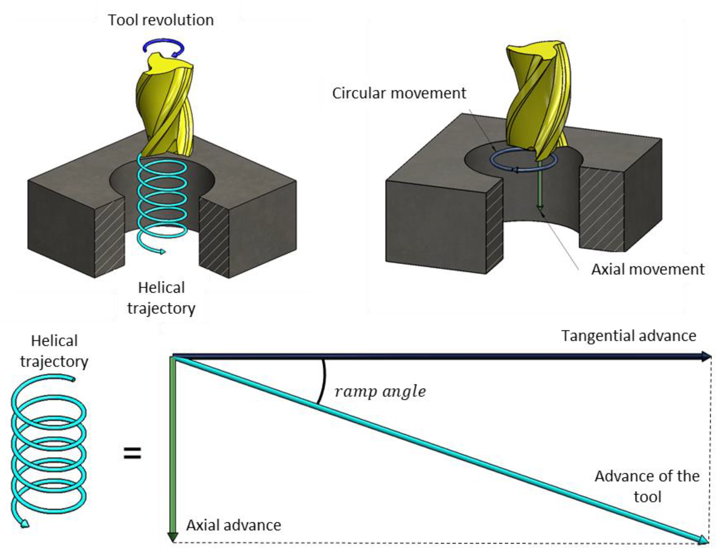
The difficulties found are associated with the kinetics of the process. In helical milling, the holes are obtained through the combination of the rotation movement of the tool together with its translation along a helical trajectory (feed rate). At the same time, the movement of the tool on the helical trajectory is a relative movement between the tool and the part that can decompose into a circular movement on the work plane and an axial movement perpendicular to it (generating the tangential and axial feed rate) (Figure 1).
In this sense, three aspects have been detected as sources of imprecision, in addition to the variability of nomenclature used.
First of all, the “Sense of rotation”. This parameter is a categorical variable that makes it necessary to duplicate experimental tests, and although the importance of the machining direction (up milling, down milling) is known in conventional milling [24,25,26], there are many helical milling research works in which there is no reference to this parameter. It is considered absolutely necessary to identify this parameter in the process in order to correctly evaluate and compare the results.
Secondly, there are the parameters that define tangential feed rate and the units used. There is a problem associated with the difference between orbital or tangential speed (Vfht) (speed developed by the centre of the tool while describing the orbit), and peripheral speed (Vft) (described by the main cutting edges of the mill). Figure 2 shows the tangential and peripheral speed of the tool in its translation movement.
V f h t = V f t · ( D b D t ) D b
V f t = f z t · z · n
The units must be correctly defined, the feed per tooth must be referred to the hole perimeter, which is related to the peripheral speed, as defined by B. Dankena and E. Brinksmeier in their respective papers [17,27]. From Equations (2) and (3) essential information for the calculations is identified and must be defined.
Table 2 shows in blue the values provided in the papers, in orange the values calculated, and in in grey where there is a different result for each spindle speed, highlighting those that are not reproducible because of an absence of information.
Millimetres per tooth or millimetres per tool revolution are the most commonly used units in the literature consulted to define the tangential feed rate, as shown in Table 2. However, providing the units in mm/tooth referring to tangential velocity without alluding to or identifying this difference between velocities or without providing additional data, may allow a misinterpretation.
Other investigations define this parameter as orbital rotation speed, expressed in millimetres per minute, understood as a speed of the centre of the tool on the helical path.
Finally, Lan Zhou proposes and defines a parameter that represents the ratio between spindle speed and orbital revolutions [28].
The choice of feed rate units will depend on the study objectives. The choice of mm·min−1 will provide more convenient information for studies related to process performance (material remove rate). However, conclusions cannot be extrapolated to cases where this parameter is measured in mm·tooth−1 because combining the different tangential feed rates with the cutting speeds generates a different feed per tooth in each case. On the other hand, if this parameter is defined as mm/tooth, we obtain different information about the process, which can easily be related to chip thickness and what it involves.
Thirdly, axial feed rate also can present difficulties of interpretation related to units. Table 3, Table 4 and Table 5 show in blue the values provided in the papers, in orange the values are calculated, and it highlights those that are not reproducible.
The tool manufacturers consulted express this data in an angle defined in degrees (α), as defined by D. Olvera et al. in their work [11]. However, there are many other ways of defining and expressing this parameter, an important number of articles consulted express this parameter in millimetres per revolution, where it must be assumed that reference is made to the revolutions of the tool (spindle), not to the revolutions on the orbital trajectory. In other research this data is also given in millimetres per revolution, with the clarification that it is about millimetres per orbital revolution (also defined as the pitch of the helix) being essential, and finding again a focus of possible errors of interpretation when the same parameter can be defined with the same units by interpreting them in two different ways. Finally, it can also be found expressed in millimetres per tooth, as indicated by D. Nespor in [30].
Figure 3 shows the decomposition of the advance movement, identifying through Equations (4)–(6) the information necessary to relate the different ways of expressing this parameter:
α = a r c t a n ( V f h a V f h t )
a p = tan α · π · D h
a p = f z a · π · D b f z t
All this shows the complexity of the process and shows the deep knowledge needed to achieve the objectives pursued. Also, it must be borne in mind that the paths must be programmed in CNC (Computer numerical control) machining and the way the kinematics information must be entered must be taken into account.
Also, the difficulty of making comparisons between different studies is reflected, and it is shown that the conclusions obtained depend on the choice and definition of parameters, being only applicable for that configuration. In addition, the absence of information may impede the reproducibility of the tests.
Finally, an experimental design has been carried out to identify and evaluate the sensitivity and main trends of the hole quality indicators with the kinematic variables of the process.

2. Materials and Methods

The high number of variables to be studied entails a high number of tests and resource consumption. Therefore, it has been decided to opt for a two-level fractional factorial experimental design. In this design a complete factorial design subset is used, allowing a reduction in the resources employed. This experimental design is selected on the assumption that higher order effects are negligible in order to obtain information on the main effects and lower order iterations. The structure of the fractional factorial design is as shown through the Table 6:
The fraction 1/2 indicates that half of the trials will be carried out, and the design resolution IV describes how the effects of a fractional factorial design form alias structures with other effects (the alias structure describes the patter of confusion in a design). In this case, no main effects form alias structure with any other main effect or two factor interactions, but some two factor interactions form alias structures with others two factor interactions and the main effects form alias structures with 3-factor interactions.
A 30 × 300 mm plate of 5 mm thick titanium alloy UNS R56400 has been selected as a sample. Holes of 6.35 mm diameter will be made. The composition of the material is shown in Table 7.
The selected tool is from the manufacturer KENDU, its reference is uniKENCut 6302.60. It is a tool manufactured according to DIN 6527K standards, 4 mm diameter, 42° ÷ 47° helical angle, WC-Co (10% Co) without coating. The main dimensions and features are shown in Table 8.
The tests were carried out in the absence of lubricant. The cutting parameters have been selected from the manufacturer’s advice seeking to optimize the performance of the process, with the result shown Table 9.
The tests were carried out on a 5-axis machining centre Kondia Five 400 (Elgoibar, Guipúzcoa, Spain), controlled by a control system Heidenhain iTNC530 (Traunreut, Baviera, Germany). During test 6 the tool broke, preventing the realization of this combination of parameters.
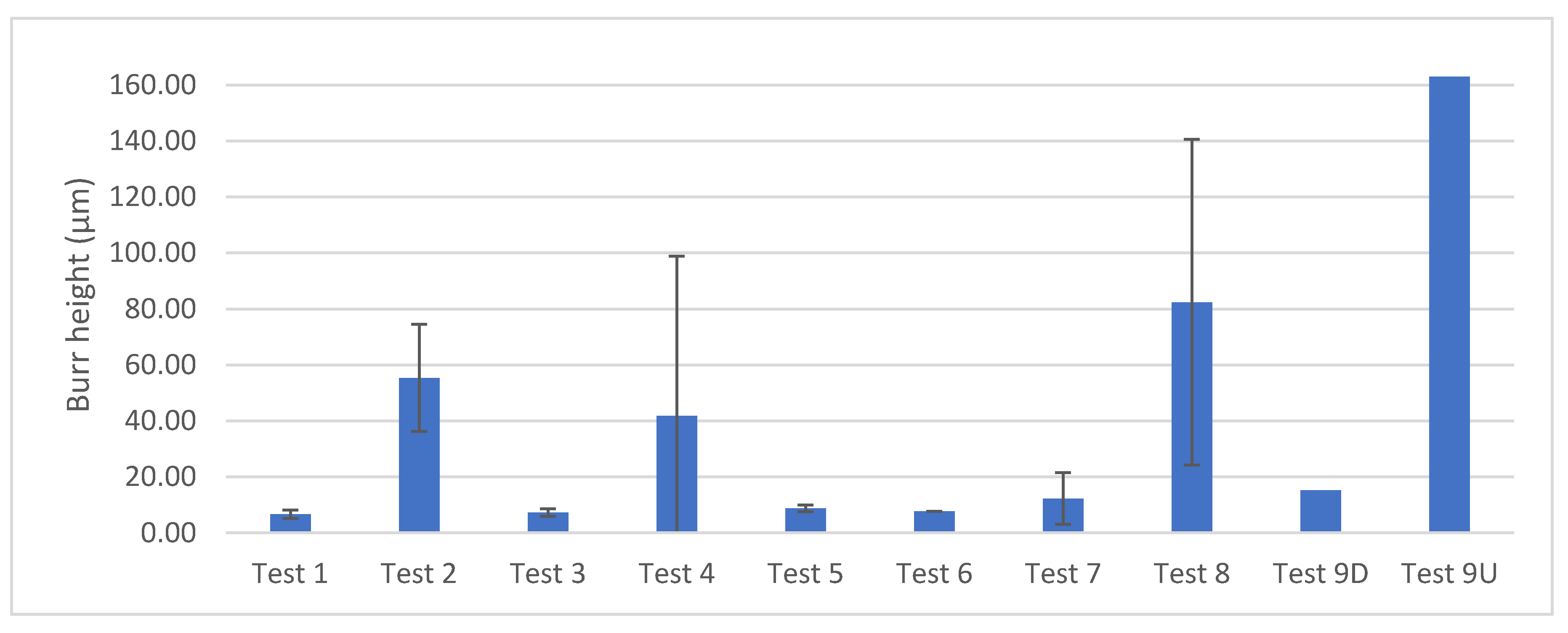
The quality of the holes was analysed from three indicators (burr height, roughness and diameter). A stereoscopic microscope was used to detect the burrs (Nikon, SMZ 800, Tokyo, Japan) (Figure 4a). After a visual inspection of the images, the areas where the burr can be seen are identified and with the help of a roughness-meter (Mahr Perthometer PGK 120, Göttingen, Germany) several surface profiles were obtained (Figure 4b). For the correct measurement of the burr height, the values of the obtained profiles are treated mathematically generating a line with the method of the “least squares” taken as a reference the surface of the specimen and as a measure of the burr height the most unfavourable case (Figure 4c). In cases where this defect is not clearly identified, a measurement is made on a random generatrix to obtain a profile that will be used to measure its height.
The same roughness meter has been used for the evaluation of surface quality. The surface quality has been evaluated from the arithmetic roughness parameter (Ra) under UNE-EN ISO 4288:1998. Two measurements have been made on the surface of the hole at 0° and 180° as shown in Figure 5.
Finally, the diameters have been evaluated using an internal micrometre of three contacts Micromar 44 A (Esslingen am Neckar, Germany), making two equidistant measurements in each hole (Figure 6).

3. Results and Discussion

3.1. Tool Wear

During the tests, the appearance of wear was detected (Figure 7). Despite the low number of holes made by each tool, a different wear mechanism can be observed in the front area of the cutting edge and in the peripheral area of the cutting edge, as indicated by Hao Li in his work [14]. This suggests that tool wear under dry machining occurs progressively and rapidly.
After macroscopic analysis, the main wear mechanisms are microfracture and adhesion. Coloured areas can also be observed as a consequence of being thermally affected.
In this work, the catastrophic failure of the tool was caused by an excess of adhered material. This can be caused by a combination of wear mechanisms, with adhesive wear occurring with increasing temperature due to fractures at the cutting edges.

3.2. Surface Quality

Surface quality has been evaluated through the arithmetic mean roughness parameter (Ra) because it is the parameter used by the aerospace sector, generally with Ra below than 1.6 μm [36].
The value used for the analysis is the average of two measurements taken in each hole. Figure 8 shows the values obtained in the three repetitions of each combination of parameters. It shows a visual differentiation between the up-milling and down-milling tests.
In spite of the observed wear, the repeatability of the tests is high, with the largest deviation being found in test 5 with a standard deviation value of 0.30 µm.
The values obtained are within the ranges observed in other investigations, for example [14] found roughness between 0.4 and 0.8 µm, relating this increase with the tool wear and reaching a maximum of 0.96 µm when tool failure. Some research corroborates that the results in helical milling are better than those obtained in conventional drilling obtaining an average of 0.61 µm in [11], and values between 0.2 and 0.7 in [22,32], nevertheless Zhao in [15] found better results in conventional drilling. All these values are in line with the values obtained in this experiment.
The result obtained have been statistically processed in Minitab® 18.1 (Minitab, LLC, Pennsylvania State, PA, USA) software. The influence of each parameter or combination of them on Ra is reflected in the Pareto Chart of the Standardized Effects graph (Figure 9), where it is verified that the direction of rotation (Down or Up milling) is the parameter with the greatest influence, followed by the combination of two factors, and to a lesser extent the tangential feed rate per tooth.
Figure 10 shows the main effects of the parameters on roughness, where it is observed that the down-milling strategy provides lower roughness values than those obtained with up-milling, and to a lesser extent an increase in the tangential feed rate per tooth (fzt) improves surface quality.
The trends are not exactly the same as the results obtained in [32], where they coincide in the trend in the tangential feed rate but not in the axial feed rate. In both, an increase in parameters leads to an increase in roughness. On the other hand, an influence of cutting speed in the case of dry machining was observed associated with the adhesion caused by high temperature; nevertheless in the present study this parameter presents the least influence on roughness.
This effect was already known in peripheral milling, and in helical milling it is shown to have a very similar behaviour. Therefore, the fact that better qualities appear in down milling may be due to the same reasons, among which are that no burnishing or reworking of the chips appears.
Table 10 shows the results of the P value and F value for the test parameters. Observing the data shows that both the strategy, tangential advance and the combination of two parameters are below 0.05 (95% confidence level), with the direction of rotation being the most evident next to a higher f-value (indicating its significance). The strategy is the most relevant factors in the variation of Ra, obtaining a p-value = 0.000, lower than the level of significance (α = 0.05). In addition, f-value is greater than the rest of the parameters (f = 68.15), confirming once again the importance of the direction of rotation in Ra during the helical milling process.

3.3. Diameter

The value used for the diameter analysis was the average of the values obtained in the two measurements of each hole. Figure 11 shows the values obtained in the three repetitions of the tests for each combination of parameters. As in the roughness, there is little variation between test repetitions, with the largest deviation found in test 2, with a standard deviation of 8 µm.
It can be seen that depending on the parameters used we can find deviations above and below the programmed diameter. However, other researchers only find deviations in one of the senses. It was found by [18] that all deviations are above the desired diameter, but on the contrary [11,14,28] obtained lower values than those programmed. In all cases, good accuracy is attributed to the process, with values between IT6-IT11 according to ISO 286-1:2010.
The influence of each parameter or combinations of them on the diameter of the hole is reflected in the Pareto chart of the standardized effects graph (Figure 12), where it is verified that the axial feed rate per tooth (fza) is the parameter with the greatest influence, followed by a combination of two factors and to a lesser extent the tangential feed rate per tooth (fzt). Figure 13 shows the main effects of the parameters on the diameter, where it is observed that lower axial feed rate generates smaller hole diameters.
The diameter obtained may be closely related to the forces during milling, since an increase in these forces in the radial direction may cause them to deflect. At the same time, temperature can also play an important role, which can be related to the thickness chip.
Table 11 shows that both the axial feed rate per tooth (fza), two parameter combinations and to a lesser extent tangential feed rate per tooth (fzt) present p-values below 0.05, with the axial advance being the one that presents greater evidence next to a greater f-value, indicating its significance.

3.4. Burr Height

The burr defect forms most pronounced at the exit of the hole and, therefore, it is in that area where the measurement is made.
With the help of an optical microscope, a visual inspection of the holes has been carried out, identifying the areas where the burr defect has appeared most clearly.
Figure 14 shows the values obtained in the three repetitions of the tests for each combination of parameters. In contrast to the roughness and diameter, the burr formation presents important variations between its repetitions, the biggest difference being found in test 8 with a standard deviation value of 58.21 µm. These deviations increase notably in the tests with higher cutting speed (Vc), finding that the variations between repetitions for low values of cutting speed are very small.
In [14], the burr is classified in three differentiates stages. In the first place, stage I is where there are burrs heights between 0 and 0.1, stage II is where the burr heights between 0.1 and 0.3, and a last stage defines that the burr would be excessive. According to this classification, the results obtained would fit in stage I with the worst results remaining in stage II, except the case where tool broke (not represented).
Figure 15 shows the Pareto chart of the standardized diagram of effects, where no parameter appears as significant. However, in Figure 16 there is a marked slope that indicates the trend of the term. In this way, it can be observed that there is a tendency to increase when there are greater values of cutting speed, tangential advance and up-milling strategy, although the increase in the height of the burr is related to the increase in temperature and the axial forces, there is not sufficient evidence to statistically assure their significance.
Burr formation is a complex process that can involve many uncontrolled variables, including tool wear and temperature. This could explain the variability between repetitions and, therefore, makes it difficult to obtain a significant parameter from the tests carried out.
Table 12 shows the analysis of variance where it is observed that none of the terms have a p-value below 0.05, indicating that there is no evidence that any term is significant. In spite of this, the terms’ cutting speed and tangential advance are the closest and have a greater f value, being reflected in the slope of the effect’s graphs.

3.5. Response Optimization

Finally, a mathematical treatment has been carried out based on the results obtained, whose objective is to reach the desired diameter with a minimum roughness and burr height. For this purpose, all characteristics were considered the same weight and the same importance. Table 13 shows the objective of the defined quality parameters and results obtained.
Table 14 presents the solution obtained. It shows a composite desirability close to 1, which indicates that the settings seem to achieve favourable results for all responses. In addition, the highest probable value for the mean response and prediction of the highest probable value of each response has been determined with a 95% confidence interval.

4. Conclusions

The bibliographic review has made it possible to identify the sources of problems associated with the parameters that define the movement of helical milling. Kinetics has been defined from different studies, proposing a unique nomenclature to unify and standardize the process parameters and its units. This step would allow the comparison of different works.
On the other hand, it has been possible to develop an experimental design with a reduced number of combinations. The results show the main trends of the hole quality indicators against the kinematic variables of the helical milling process.
The results have shown the sensitivity of the quality indicators of the hole. The helical milling conditions that have most affected the roughness of the machined surface have been milling direction (strategy) and to a lesser extent the tangential feed rate per tooth (fzt). The lowest roughness values are found with down milling and an increase in the tangential feed rate per tooth.
Values above and below the programmed value have been found. It has been possible to observe the influence that the feed-rate parameters (axial and tangential) have on the diameter of the hole, which may be strongly related to the cutting forces.
The burr formation is the most unstable defect, and from which it has not been possible to obtain sufficient evidence to affirm the influence of the kinematic parameters, which may be due to uncontrolled factors such as temperature or tool wear.

Author Contributions

F.J.P.-M. and S.R.F.-V. developed drilling tests and data treatment. F.J.P.-M. and S.R.F.-V. analyzed the influence of the parameters involved. F.J.P.-M. collaborated in preparing figures and tables and F.J.P.-M., J.S.G. and S.R.F.-V. wrote the paper. All authors have read and agreed to the published version of the manuscript.

Funding

This research received no external funding.

Conflicts of Interest

The authors declare no conflict of interest.

References

  1. Welcome to the Clean Sky | Clean Sky. Available online: https://www.cleansky.eu/ (accessed on 16 December 2019).
  2. Supporting Clean Sky—Innovation – Airbus. Available online: https://www.airbus.com/newsroom/stories/supporting-clean-sky.html (accessed on 16 December 2019).
  3. Debnath, S.; Reddy, M.M.; Yi, Q.S. Environmental friendly cutting fluids and cooling techniques in machining: A review. J. Clean. Prod. 2014, 83, 33–47. [Google Scholar] [CrossRef]
  4. Sreejith, P.S.; Ngoi, B.K.A. Dry machining: Machining of the future. J. Mater. Process. Technol. 2000, 101, 287–291. [Google Scholar] [CrossRef]
  5. Paul, S.; Chattopadhyay, A.B. Environmentally conscious machining and grinding with cryogenic cooling. Mach. Sci. Technol. 2006, 10, 87–131. [Google Scholar] [CrossRef]
  6. Ali, S.; Polytechnique, N.; Songmene, V.; Sup, T. Green Machining of Ti-6Al-4V Under Minimum Quantity Lubrication (MQL) Condition. In Machining of Titanium Alloys; Davim, J.P., Ed.; Materials Forming, Machining and Tribology; Springer: Berlin/Heidelberg, Germany, 2014; Volume 29, pp. 58–62. ISBN 978-3-662-43901-2. [Google Scholar]
  7. Kohse-Höinghaus, K.; Troe, J.; Grabow, J.-U.; Olzmann, M.; Friedrichs, G.; Hungenberg, K.-D. Green Manufacturing Processes and Systems; Davim, J.P., Ed.; Materials Forming, Machining and Tribology; Springer: Berlin/Heidelberg, Germany, 2013; Volume 20, ISBN 978-3-642-33791-8. [Google Scholar]
  8. Pereira, R.B.D.; Brandão, L.C.; de Paiva, A.P.; Ferreira, J.R.; Davim, J.P. A review of helical milling process. Int. J. Mach. Tools Manuf. 2017, 120, 27–48. [Google Scholar] [CrossRef]
  9. Brinksmeier, E.; Fangmann, S. Burrs - Analysis, Control and Removal; Aurich, J.C., Dornfeld, D., Eds.; Springer: Berlin/Heidelberg, Germany, 2010; ISBN 978-3-642-00567-1. [Google Scholar]
  10. Liu, D.; Tang, Y.; Cong, W.L. A review of mechanical drilling for composite laminates. Compos. Struct. 2012, 94, 1265–1279. [Google Scholar] [CrossRef]
  11. Olvera, D.; de Lacalle, L.N.L.; Urbikain, G.; Lamikiz, A.; Rodal, P.; Zamakona, I. Hole making using ball helical milling on titanium alloys. Mach. Sci. Technol. 2012, 16, 173–188. [Google Scholar] [CrossRef]
  12. Sun, D.; Lemoine, P.; Keys, D.; Doyle, P.; Malinov, S.; Zhao, Q.; Qin, X.; Jin, Y. Hole-making processes and their impacts on the microstructure and fatigue response of aircraft alloys. Int. J. Adv. Manuf. Technol. 2018, 94, 1719–1726. [Google Scholar] [CrossRef] [Green Version]
  13. Wang, H.; Qin, X.; Li, H.; Tan, Y. A comparative study on helical milling of CFRP/Ti stacks and its individual layers. Int. J. Adv. Manuf. Technol. 2016, 86, 1973–1983. [Google Scholar] [CrossRef]
  14. Li, H.; He, G.; Qin, X.; Wang, G.; Lu, C.; Gui, L. Tool wear and hole quality investigation in dry helical milling of Ti-6Al-4V alloy. Int. J. Adv. Manuf. Technol. 2014, 71, 1511–1523. [Google Scholar] [CrossRef]
  15. Zhao, Q.; Qin, X.; Ji, C.; Li, Y.; Sun, D.; Jin, Y. Tool life and hole surface integrity studies for hole-making of Ti6Al4V alloy. Int. J. Adv. Manuf. Technol. 2015, 79, 1017–1026. [Google Scholar] [CrossRef] [Green Version]
  16. Urbicain, G.; Olvera, D.; De Lacalle, L.N.L.; Zamakona, I.; Rodal, P. New strategies for hole making in Ti-6Al-4V. AIP Conf. Proc. 2009, 1181, 361–369. [Google Scholar]
  17. Brinksmeier, E.; Fangmann, S.; Meyer, I. Orbital drilling kinematics. Prod. Eng. 2008, 2, 277–283. [Google Scholar] [CrossRef]
  18. Qin, X.D.; Sun, X.T.; Wang, Q.; Chen, S.M.; Li, H. Comparative Study on Helical Milling and Drilling of Ti-6Al-4V. Key Eng. Mater. 2012, 499, 200–204. [Google Scholar] [CrossRef]
  19. Jawahir, I.S.; Brinksmeier, E.; M’Saoubi, R.; Aspinwall, D.K.; Outeiro, J.C.; Meyer, D.; Umbrello, D.; Jayal, A.D. Surface integrity in material removal processes: Recent advances. CIRP Ann. 2011, 60, 603–626. [Google Scholar] [CrossRef]
  20. Gómez-Parra, A.; Puerta, F.J.J.; Rosales, E.I.I.; González-Madrigal, J.M.M.; Marcos, M. Study of the influence of cutting parameters on the Ultimate Tensile Strength (UTS) of UNS A92024 alloy dry turned bars. Procedia Eng. 2013, 63, 796–803. [Google Scholar] [CrossRef] [Green Version]
  21. Davim, J.P. (Ed.) Surface Integrity in Machining, 2009th ed.; Springer: London, UK, 2010; ISBN 978-1-84882-873-5. [Google Scholar]
  22. Sun, D.; Keys, D.; Jin, Y.; Malinov, S.; Zhao, Q.; Qin, X. Hole-making and its Impact on the Fatigue Response of Ti-6AL-4V Alloy. Procedia CIRP 2016, 56, 289–292. [Google Scholar] [CrossRef] [Green Version]
  23. Zhou, R.; Yang, W. Analytical modeling of residual stress in helical end milling of nickel-aluminum bronze. Int. J. Adv. Manuf. Technol. 2017, 89, 987–996. [Google Scholar] [CrossRef]
  24. Mohn, W.R.; Bergh, M.R.; Van Den Slawson, T.; Mamon, O.L.; Buck, M.E.; Plank, D.; Wood, R.; Koster, W.P.; Gurganus, T.B. ASM Handbook—Machining Process; ASM International: Novelty, OH, USA, 1989; ISBN 978-0871700223. [Google Scholar]
  25. Hadi, M.A.; Ghani, J.A.; Che Haron, C.H.; Kasim, M.S. Comparison between up-milling and down-milling operations on tool wear in milling Inconel 718. Procedia Eng. 2013, 68, 647–653. [Google Scholar] [CrossRef] [Green Version]
  26. Sonja, J.; Dražen, B.; Sandra, T. Flank Wear in Down and Up Milling. Ann. Proc. DAAAM Int. 2012, 23, 251–254. [Google Scholar]
  27. Denkena, B.; Boehnke, D.; Dege, J.H. Helical milling of CFRP-titanium layer compounds. CIRP J. Manuf. Sci. Technol. 2008, 1, 64–69. [Google Scholar] [CrossRef]
  28. Zhou, L.; Dong, H.; Ke, Y.; Chen, G. Analysis of the chip-splitting performance of a dedicated cutting tool in dry orbital drilling process. Int. J. Adv. Manuf. Technol. 2017, 90, 1809–1823. [Google Scholar] [CrossRef]
  29. Rey, P.A.; LeDref, J.; Senatore, J.; Landon, Y. Modelling of cutting forces in orbital drilling of titanium alloy Ti-6Al-4V. Int. J. Mach. Tools Manuf. 2016, 106, 75–88. [Google Scholar] [CrossRef]
  30. Denkena, B.; Nespor, D.; Rehe, M.; Dege, J.H. Process Force Prediction in Orbital Drilling of Process Force Prediction in Orbital Drilling of TiAl6V4. In Proceedings of the 9th International Conference on Advanced Manufacturing Systems and Technology (AMST’11), Mali Losinj, Croatia, 16–17 June 2011; 2016; pp. 113–128. [Google Scholar]
  31. Liu, J.; Ren, C.; Qin, X.; Li, H. Prediction of heat transfer process in helical milling. Int. J. Adv. Manuf. Technol. 2014, 72, 693–705. [Google Scholar] [CrossRef]
  32. Qin, X.; Gui, L.; Li, H.; Rong, B.; Wang, D.; Zhang, H.; Zuo, G. Feasibility Study on the Minimum Quantity Lubrication in High-Speed Helical Milling of Ti-6Al-4V. J. Adv. Mech. Des. Syst. Manuf. 2012, 6, 1222–1233. [Google Scholar] [CrossRef] [Green Version]
  33. Fernández-Vidal, S.R.; Mayuet, P.; Rivero, A.; Salguero, J.; Del Sola, I.; Marcos, M. Analysis of the Effects of Tool Wear on Dry Helical Milling of Ti6Al4V Alloy. Procedia Eng. 2015, 132, 593–599. [Google Scholar] [CrossRef] [Green Version]
  34. Ji, C.; Li, Y.; Qin, X.; Zhao, Q.; Sun, D.; Jin, Y. 3D FEM simulation of helical milling hole process for titanium alloy Ti-6Al-4V. Int. J. Adv. Manuf. Technol. 2015, 81, 1733–1742. [Google Scholar] [CrossRef] [Green Version]
  35. Qin, X.; Zhang, X.; Li, H.; Rong, B.; Wang, D.; Zhang, H.; Zuo, G. Comparative analyses on tool wear in helical milling of Ti-6Al-4V using diamond-coated tool and TiAlN-coated tool. J. Adv. Mech. Des. Syst. Manuf. 2014, 8, JAMDSM0004. [Google Scholar] [CrossRef] [Green Version]
  36. Berzosa, F.; Agustina, B.; De Rubio, E.M. Tool Selection in Drilling of Magnesium UNSM11917 Pieces under Dry and MQL Conditions based on Surface Roughness. Procedia Eng. 2017, 184, 117–127. [Google Scholar] [CrossRef]
Figure 1. Kinetic decomposition of helical movement.
Applsci 10 00845 g001
Figure 2. Tangential and peripheral speed.
Applsci 10 00845 g002
Figure 3. Feed decomposition: (a) Decomposition of the feed rate in tangential speed and axial speed, (b) Decomposition advance per helical revolution in pitch per helical revolution and perimeter of the helix trajectory.
Applsci 10 00845 g003
Figure 4. Burr evaluation procedure. (a) Visual inspection. (b) Obtaining the surface profile. (c) Burr weight measurement.
Applsci 10 00845 g004
Figure 5. Measurement procedure of surface quality at 0° and 180° degrees.
Applsci 10 00845 g005
Figure 6. (a) Evaluation with micrometre of three contacts. (b) Diameter evaluation positions.
Applsci 10 00845 g006
Figure 7. Tool wear after the test.
Applsci 10 00845 g007
Figure 8. Graph of roughness results.
Applsci 10 00845 g008
Figure 9. Pareto chart of the standardized effects for Ra.
Applsci 10 00845 g009
Figure 10. Main effects plot for Ra.
Applsci 10 00845 g010
Figure 11. Graph of diameter results.
Applsci 10 00845 g011
Figure 12. Pareto chart of the standardized effects for diameter.
Applsci 10 00845 g012
Figure 13. Effects plot for diameter.
Applsci 10 00845 g013
Figure 14. Measured burr height values.
Applsci 10 00845 g014
Figure 15. Pareto chart of the standardized effects for burr height.
Applsci 10 00845 g015
Figure 16. Effect plot for burr height.
Applsci 10 00845 g016
Table 1. Proposed Nomenclature for kinematic parameters of the helical milling process.
ParameterNomenclatureUnits
Cutting speedVcm·min−1
Feed rateVfmm·min−1
Tangential speedVfhtmm·min−1
Peripheral speedVftmm·min−1
Axial speedVfhamm·min−1
Tangential speed per toothfztmm·tooth−1
Axial speed per toothfzamm·tooth−1
Ramp angleαdegrees
Pitch per helical revolutionapmm
Bore diameterDbmm
Tool diameterDtmm
Helix diameterDhmm
Spindle speednRPM
Tool teethzUnits
Table 2. Values provided in the publication consulted for tangential movement.
Ref.N° of Teeth (z)mm·Tooth−1mm·Rev−1mm·Min−1Spindle Speed·Helical Rev.−1
[11]20.07 0.014
[14]40.04 0.016
[15]40.04 0.016
[29]30.04 0.012
[30]20.07 0.014
[18]-0.050.08 *
[16]-0.07 *
[31]40.04 0.016
[32]-0.030.040.050.06*
[13]40.04 0.016
[33]20.0250.03750.05 0.050.0750.1
[22]40.01 0.04
[34]4 200240280320
[35]-**480 *
[28]5 20406080
* Incomplete information.
Table 3. Values provided in the publication consulted for axial movement in millimetre per tool revolution and millimetre per tooth.
Ref.N° of Tooth (z)mm·Rev−1 (Spindle)mm·Tooth−1
[14]40.20 0.050
[15]40.20 0.050
[29]30.010.3 0.0030.1
[13]40.10 0.030
[34]40.150.20.30.30.0400.10.10.1
[31]40.100.2 0.0300.1
[30]20.01 0.010
Table 4. Values provided in the publication consulted for axial movement in ramp angle and millimetre per helical revolution.
Ref.ØhRamp AngleMm·Helical Rev.−1
[11]44.55° 0.5
[22]-* 0.2
[18]30.61°1.22° 0.10.2
[16]- * 0.5
[32]40.46°0.68°0.9°1.1°0.10.150.20.3
[35]- * 0.2
* Incomplete information.
Table 5. Values provided in the publication consulted for axial movement in millimetre per minute and millimetre per second.
Ref.mm·Min−1mm·S−1
[33]65971301952603901.11.62.23.34.36.5
[28]612 0.10.2
Table 6. Fractional factorial design.
Design Summary
Factors:4Base Design:4; 8Resolution:IV
Runs:26Replicates:3Fraction:1/2
Blocks:1Center pts (total):2
Design Generator: D = ABC
Alias Structure
I + ABCDB + ACDD + ABC AC + BD
A + BCDC + ABDAB + CD AD + BC
Table 7. Component elements’ properties.
Aluminum, AlCarbon, CHydrogen, HIron, FeNitrogen, NOxygen, OTitanium, TiVanadium, V
≤6.5%≤0.08%≤0.015%≤0.30%≤0.05%≤0.20%90%4.0%
------www.MatWeb.com
Table 8. Main tool features.
DDILZD3L3cCh Applsci 10 00845 i001
F8H6
4685433.7170.20.1
Table 9. Summary of machining parameters.
TestVc (m·Min−1)n (Rpm)fzt (mm·Tooth−1)Vfht (mm·Min−1)fza (mm·Tooth−1)Vfha (mm·Min−1)Strategy
18063660.0150106.0200.000509.549Down
216012,7320.0150212.0390.0005019.099Up
38063660.0300212.0390.000509.549Up
416012,7320.0300424.0790.0005019.099Down
58063660.0150106.0200.0010019.099Up
616012,7320.0150212.0390.0010038.197Down
78063660.0300212.0390.0010019.099Down
816012,7320.0300424.0790.0010038.197Up
9D12095490.0225238.5440.0007521.486Down
9U12095490.0225238.5440.0007521.486Up
Table 10. Variance analysis for Ra.
Sourcef-Valuep-Value
Model15.550.000
Linear23.360.000
Vc0.140.715
fzt5.510.032
fza3.800.069
Strategy68.150.000
2-Way Interactions5.630.008
Vc * fzt13.870.002
Vc * fza5.540.032
Vc * Strategy2.160.161
Table 11. Variance analysis for diameter.
Sourcef-Valuep-Value
Model41.540.000
Linear61.650.000
Vc2.310.148
fzt5.950.027
fza210.060.000
Strategy0.690.420
2-Way Interactions10.530.000
Vc * fzt7.890.013
Vc * fza0.280.606
Vc * Strategy17.830.001
Table 12. Variance analysis for burr height.
Sourcef-Valuep-Value
Model1.580.213
Linear2.320.102
Vc3.930.065
fzt0.730.406
fza0.000.997
Strategy2.890.108
2-Way Interactions0.570.644
Vc * fzt 0.560.467
Vc * fza0.040.853
Vc * Strategy1.410.252
Table 13. Parameter optimization.
ResponseGoalLowerTargetUpperWeightImportance
Burr heightMinimum 5.36441162.97211
DiameterTarget6.34356.350006.39811
RaMinimum 0.120001.21511
Table 14. Response optimization solution.
VcfztfzaStrategyComposite Desirability
1600.0150.0005245Down0.985158
95% Upper 95% Upper
ResponseFitConfidence BoundPrediction Bound
Burr height10.8061.60100.3
Diameter6.356.366.36
Ra0.13050.280.39

