Design and Evaluation of Uniform LED Illumination Based on Double Linear Fresnel Lenses
by
 ,
,
Hoang Vu
1, 
Ngoc Minh Kieu
2,3,
Do Thi Gam
4,
Seoyong Shin
1,*,
Tran Quoc Tien
2,3,* and
Ngoc Hai Vu
5,* 1
Department of Information and Communication Engineering, Myongji University, 116 Myongji-ro, Cheoin-gu, Yongin, Gyeonggi-do 17058, Korea
2
Institute of Materials Science, Vietnam Academy of Science and Technology, 18 Hoang Quoc Viet, Cau Giay, Hanoi 1000, Vietnam
3
Vietnam Academy of Science and Technology, Graduate University of Science and Technology, 18 Hoang Quoc Viet, Cau Giay, Hanoi 11307, Vietnam
4
Vietnam Academy of Science and Technology, Center for High Technology Development, Hanoi 11307, Vietnam
5
Faculty of Electrical and Electronics Engineering and Phenikaa Institute for Advanced Study, Phenikaa University, Yen Nghia, Ha-Dong District, Hanoi 12116, Vietnam
*
Authors to whom correspondence should be addressed.
Appl. Sci. 2020, 10(9), 3257; https://0-doi-org.brum.beds.ac.uk/10.3390/app10093257
Submission received: 31 March 2020
/
Revised: 29 April 2020
/
Accepted: 4 May 2020
/
Published: 7 May 2020
(This article belongs to the Collection Optical Design and Engineering)
Abstract
:Redistribution of LED radiation in lighting is necessary in many applications. In this article, we propose a new optical component design for LED lighting to achieve a higher performance. The design consists of a commercial collimator and two linear Fresnel lenses. The LED radiation is collimated by a collimator and redistributed by double linear Fresnel lenses to create a square-shaped, uniform distribution. The linear Fresnel lenses design is based on Snell’s law and the “edge-ray principle”. The optical devices are made from poly methyl methacrylate (PMMA) using a high-speed computer numerical control (CNC) machine. The LED prototypes with complementary optics were measured, and the optical intensity distribution was evaluated. The numerical results showed we obtained a free-form lens that produced an illumination uniformity of 78% with an efficiency of 77%. We used the developed LED light sources for field experiments in agricultural lighting. The figures of these tests showed positive effects with control flowering criteria and advantages of harvested products in comparison with the conventional LED sources. This allows our approach in this paper to be considered as an alternative candidate for highly efficient and energy-saving LED lighting applications.
1. Introduction
In recent years, LEDs have been used in many different fields. With the highlight of energy savings, long life, and safety for users [1,2], LEDs are replacing other traditional lamps. However, LEDs have disadvantages of a wide beam angle (from 120° to 150°) depending on the type of LEDs [3] and have Lambertian distributions. Illumination should be redistributed using an integrated primary optical system or secondary optical system to control distribution shape and uniformity [4].
Utilizing free-form optics is a new trend to design secondary optical components for LEDs. The advantages of free-form optics are their unique design, compact size, and precise irradiation control [5]. In order to design a free-form lens, various methods have been proposed. For example, the Miñano group developed the simultaneous multiple-surface method (SMS method) [6] to design a collimator for LEDs [7]. This method redistributes light from the source to the reflective surface to produce a parallel beam with a beam angle of ±1.5°. This method also uses a wave-front theory of geometrical optics [8] to design a Fresnel lens with combined functions of LED collimation and redistribution for uniform illumination. Wang et al. used a light energy mapping method to make a compact freeform lens create an even distribution in many different shapes [5]. In addition, the optimal numerical method can also be used to design free surfaces for LED arrays, such as in Yu et al. [9]. All of the above methods work very well in controlling the distribution shape and producing a uniform light distribution, but they are not flexible in different types of LEDs. Equations for lens surface calculations have parameters dependent on the light source. Therefore, the lens structure must be recalculated when applied to different types of LEDs.
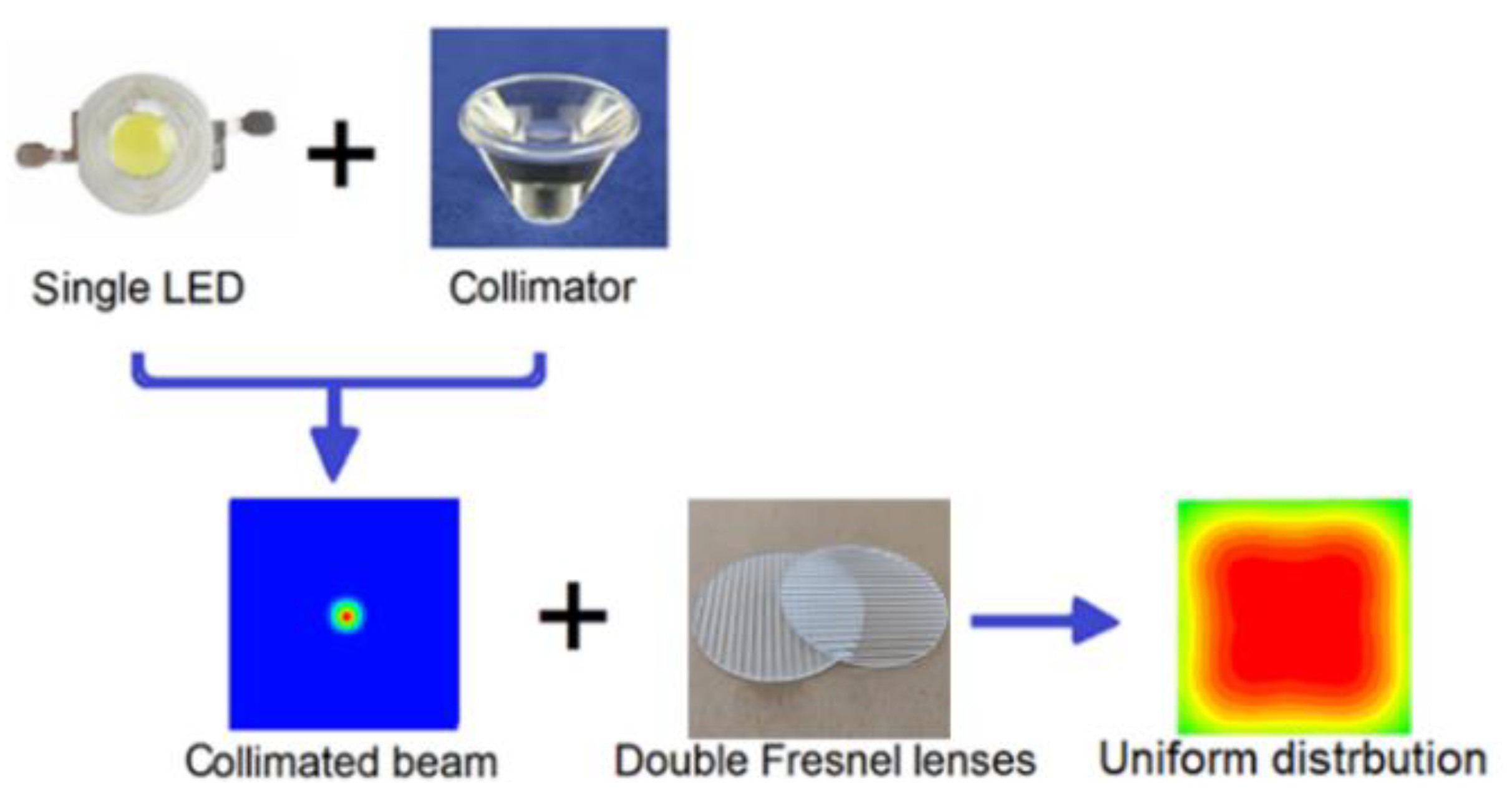
In this paper, we present a method to fabricate an optical component for a single LED, which can be applied to many types of LEDs with different beam angles to make a uniform distribution. The single LED can be a high-power LED or chip-on-board LED (COB LED). The commercial collimator lens is placed on top of the single LED to collect and collimate the light output from the LED. The collimated beam is redistributed by two linear Fresnel lenses [10] to create a uniform distribution on the receiver, as shown in Figure 1. The surface of the linear Fresnel lens is designed by using the edge-ray principle [11] and Snell’s law. The parameters of the linear Fresnel lens are not dependent on the LED chips and the collimators, where poly methyl methacrylate (PMMA) material is used to produce the lens. The results include the simulation of uniformity and efficiency of the system, comparison of simulations, and experimental results. Finally, an experiment on chrysanthemum was conducted to control flowering. Other experiments on flowering control do not present how the uniformity of the light source has an effect on plant growth, and most studies have focused on the wavelength and power of light sources [12]. Therefore, this study will be a useful reference to achieve better quality of agricultural products by improving lighting uniformity.
2. Module Design and Simulation
2.1. Module Design
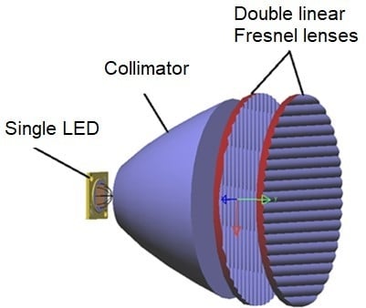
In this section we present the theory of designing a uniform illumination system for single LEDs. We propose a novel uniform illumination system consisting of three parts: LED, collimator, and two perpendicular linear Fresnel lenses, as shown as in Figure 2. The collimator was used to collimate all light from the LED source. The collimated beam from the collimator lens was redistributed using double linear Fresnel lenses to provide uniform light distribution over the given target.
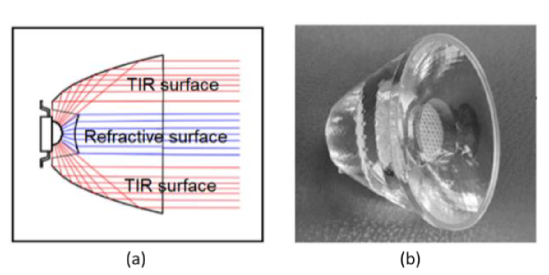
Commercial collimators are cone-like lenses. We chose a collimator from Led-link Optics Inc. [8] for our experiment. The image of the commercial collimator lens is shown in Figure 3. Collimators are often designed for point sources and a fixed wavelength to create ideal collimated beams, while LED chips are usually 1 × 1 mm or larger. Therefore, the output beams from the collimator are slightly divergent. Details will be presented in the simulation part.
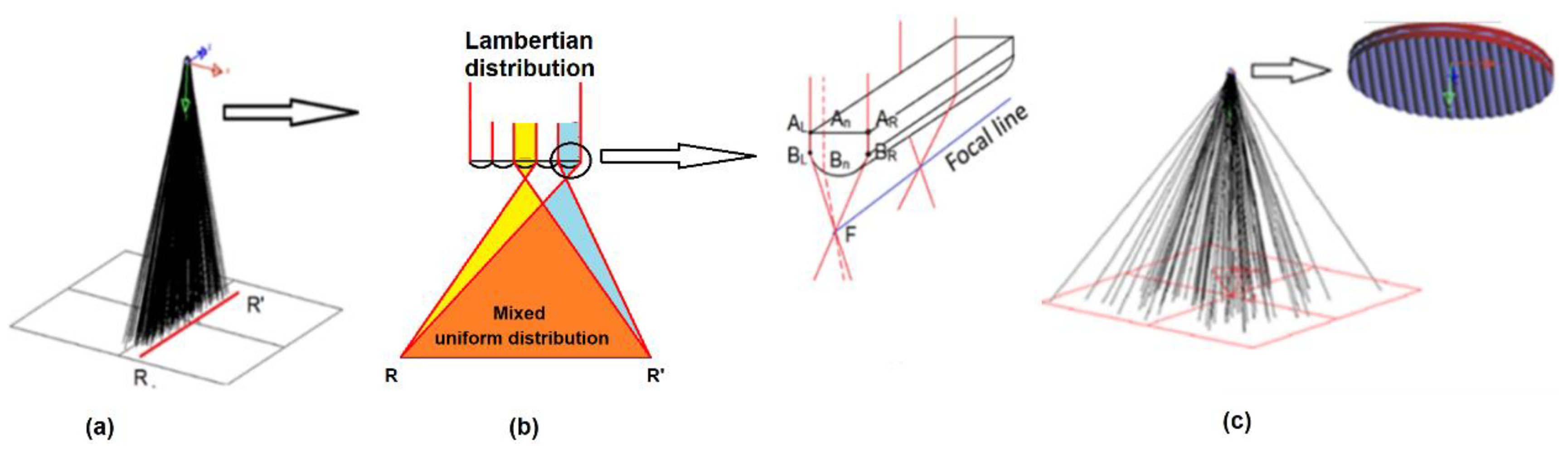
The collimated beam needs to be distributed to create uniform illumination. We used the double linear Fresnel lenses as a redistribution module, the design method as shown in Figure 4. A single linear Fresnel lens can redistribute the collimated beam in one direction in the receiver area, as shown in Figure 4a. Although the incident beam does not have a uniform distribution, the Fresnel lens consists of many small grooves, where each groove is similar to a linear convex lens. When the collimated beam passes through the linear Fresnel lens, these grooves will split the incident beam (a divided beam can be considered to have a uniform distribution) and spread it over the receiver in one direction. When two linear Fresnel lenses are perpendicular to each other, they will direct the collimated beam to spread across the receiver in two directions.
We applied the “edge-ray principle” and optical path length conservation to calculate the curves of Fresnel lens grooves. The calculation is shown in Figure 4b and consists of three steps.
Step 1: Some initial conditions of light source (collimated light beam) such as left edge , right edge of the segment, position of Fresnel lens, and receiver size (illumination space: RR ‘) are selected.
Step 2: The ray to the left edge of passes through a linear Fresnel lens groove and refracts to the right side of the receiver (point R ‘). The ray to the right edge of passes through a groove and refracts to the left side of the receiver (point R). These two rays intersect at the focal line. Similarly, the rays between the and rays must also intersect at the focal line. Based on the law of optical path length (OPL) conservation, we have Equation (1):
where , are refractive indices of air and materials of Fresnel lens, respectively. Based on the above equation, all coordinates of the segment surface curves are calculated.
Step 3: Repeat the calculation process, and all the other grooves of linear Fresnel lens are obtained by the same procedure.
Because a linear Fresnel lens distributes light in only one direction, we placed two linear Fresnel lenses perpendicularly to propagate light in two directions over the lighting area, as shown in Figure 4c. So, a two-dimensional redistribution will create a square shape on the receiver.
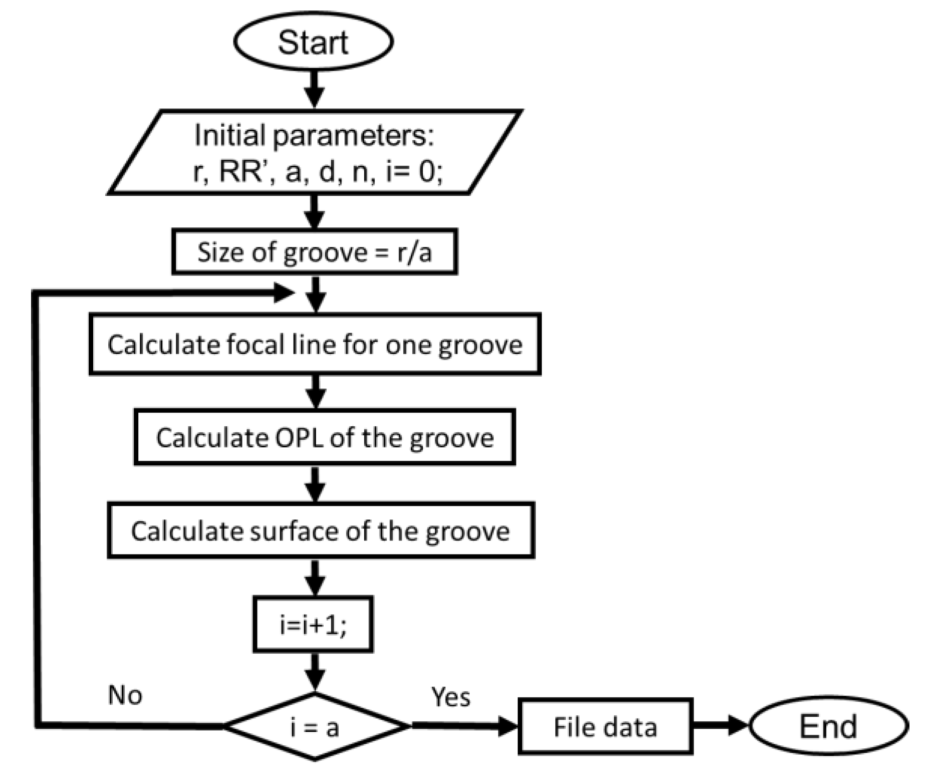
The focal line is important in this linear Fresnel lens. The LED light was focused on the focal line and was spread across the receiver RR’. Figure 5 shows the design process of the novel lens in Matlab. Some initial conditions of the light source such as Fresnel lens radius (r), number of grooves (a), distance from the light source to the receiver (d), refractive index (n), receiver size (RR’), and so forth were selected. Based on these initial conditions, the coordinates of the Fresnel lens surface in one direction was designed.
We designed a linear Fresnel lenses system for a 5W power COB LED, whose wavelength was 630 nm and had a collimator lens diameter of 100 mm. The lighting distance was 2 m, and the lighting area was 2 m × 2 m. The number of grooves of a linear Fresnel lens affects uniformity and efficiency [10]. Based on the previous results in [10], we selected a linear Fresnel lens with a groove number of 20. Table 1 shows the optical system specifications.
2.2. Simulation: Illumination Performance and Tolerance Analyses
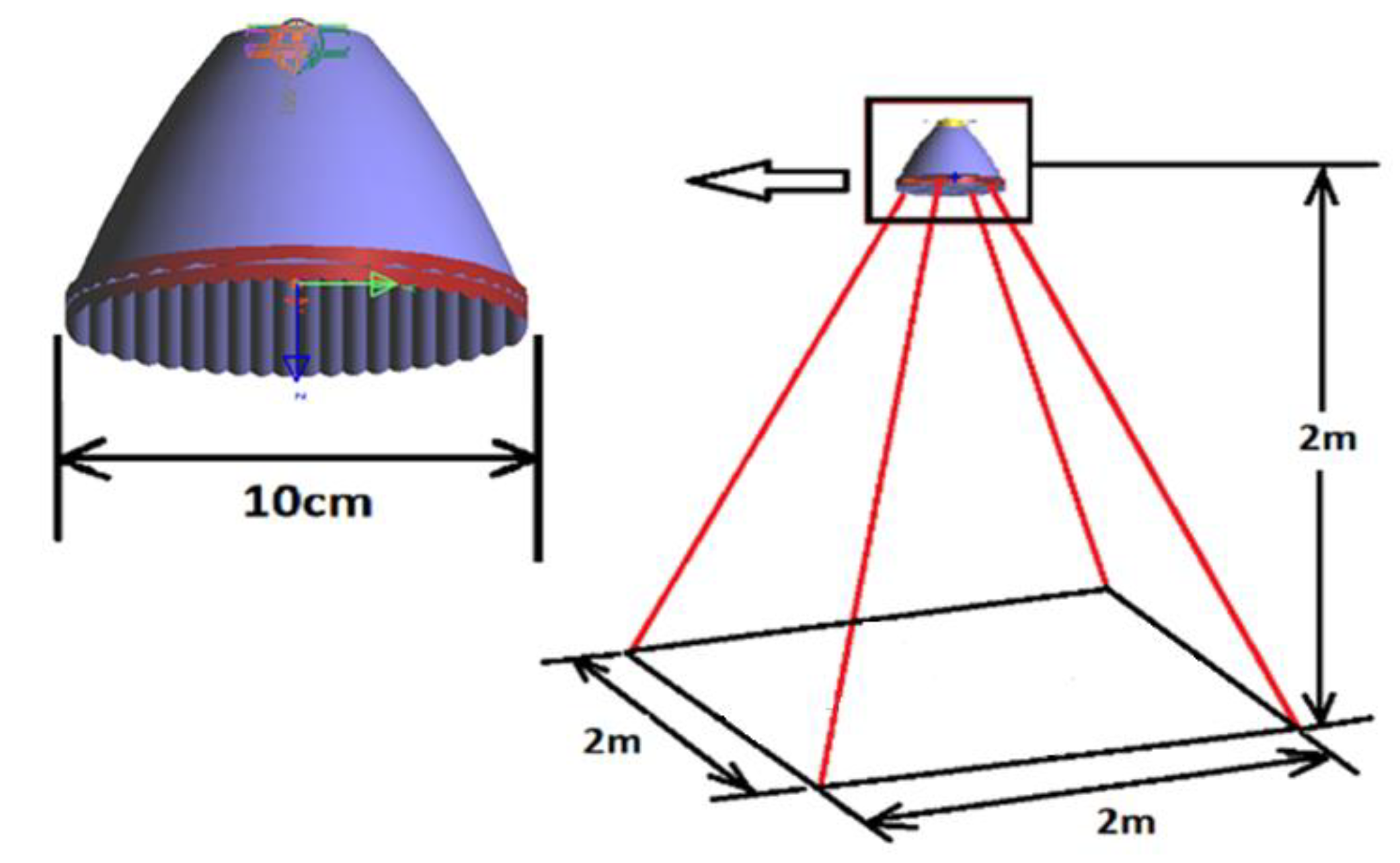
LightToolsTM optical simulation software was used to simulate the structure of the proposed LED lighting system. The structure of the simulation system is shown in Figure 6. A square lighting shape was chosen as an example to investigate the performance of the designed lighting system. As described above, the LED lighting system consisted of a single LED, a commercial collimator lens, and a set of double linear Fresnel lenses to redistribute light on the receiver. A 5W, 630 nm COB LED was used in simulations with a luminous flux of 200 lm. Fresnel lenses and the collimator lens were made of poly methyl methacrylate (PMMA) material. Double Fresnel lenses produced a uniform distribution of illumination on a 2 m × 2 m receiver. The receiver was located 2 m away from the light source.
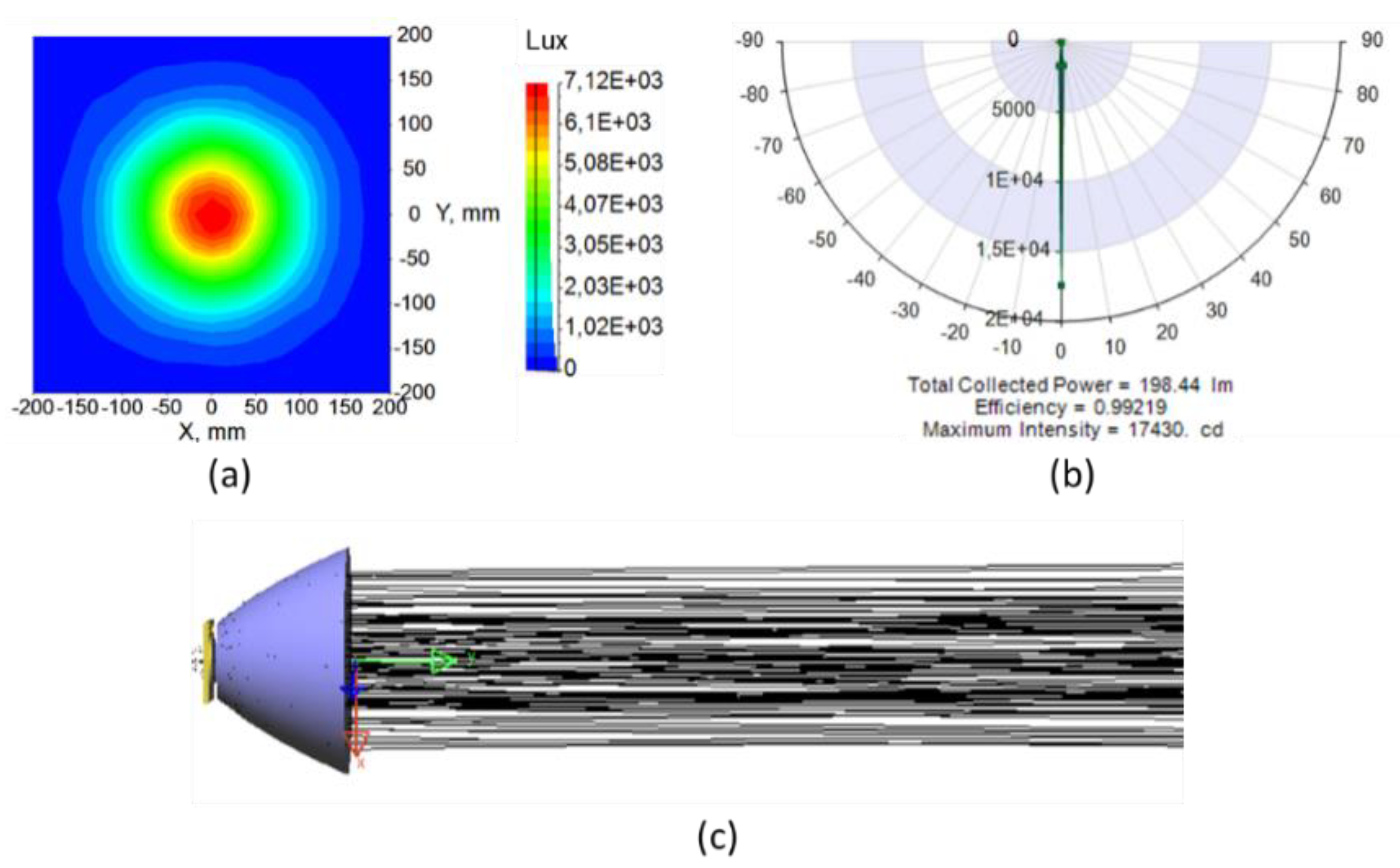
The simulation results of ray tracing of the collimator lens are shown in Figure 7. Figure 7a shows the illumination distribution in the receiver. With a lighting distance of 2 m, the distribution on the receiver area has a radius of 15 cm. Figure 7b shows the intensity distribution of the far-field receiver. It shows that the full width at half-maximum intensity angle was 1.2°. The total flux was 198.4 lm. Figure 7c intuitively displays the rays passing through the collimator lens.
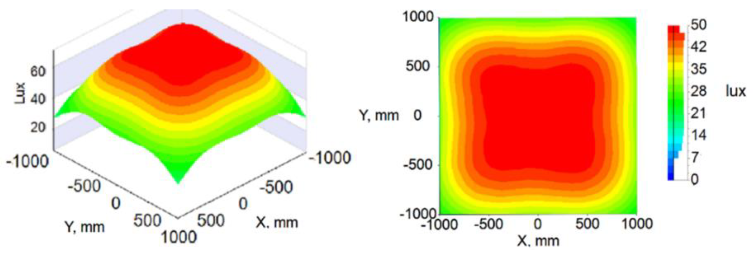
Simulation results of the optical distribution of the COB LED with the collimator and double Fresnel lenses are shown in Figure 8. It shows the illumination with a size of 2 × 2 m square on the target surface. The distribution formed a square radiation pattern with a size of 1.8 m× 1.8 m at height of 2 m, which was in agreement with the expected shape. The uniformity of illumination on the target surface was 78% with a minimum intensity of 28 lux and maximum intensity is 48 lux. The efficiency was 77%. Illumination uniformity is calculated by Equation (2):
where is the minimum intensity value and is the averaged intensity value of all the pixels.
To evaluate the losses in the system, we inserted two optical surface receivers in the simulation process, as shown in Figure 9. The system losses were from the loss of the collimator and the loss of the double Fresnel lenses. The loss of the collimator was from the material absorption and the Fresnel losses. The loss of the collimator was 1.56 Lux, as show in Figure 7b. The collimator losses are denoted by. Using LightTools™ software, can be calculated by Equation (3):
The loss of double Fresnel lenses was from the material absorption, the Fresnel losses, and the geometrical loss of the Fresnel lens. Geometrical loss of the Fresnel lens occurred when a non-ideal collimated beam was applied to this design. Although the theoretical design was optimized for an ideal parallel beam, this design still worked with a highly collimated beam, with a slight reduction in optical efficiency and uniformity. In this research, the selected collimator provided a beam with a divergence of 1.2°, so there were some staggered rays that could not reach the receiver. The loss of the double Fresnel lenses was 44.26 Lux. The double Fresnel lenses are denoted by . Using LighTools™ software, can be calculated by Equation (4):
By calculating Equations (3) and (4), respectively, we found L1 = 0.7% and L2 = 22.3%. The total loss is the sum of and and can be calculated by Equation (5):
With the parameters given above, the efficiency was found to be 77%, including the material absorption, the Fresnel losses, and the geometrical loss of the Fresnel lens.
Tolerance is an important issue for free-form lenses. In this study, the effects of the angle between the collimator lens and double linear Fresnel lens were analyzed in terms of uniformity and efficiency as shown in Figure 10. Figure 10a–c shows the effects of the line distributions along the X axis and Y axis across the center of the illuminated area for dT angles of 2°, 3°, and 4°. Figure 10d shows the results of simulations of the efficiency and the uniformity as a function of angle tolerance. When the deflection angle dT of the elements increased from 0° to 4°, the efficiency and the uniformity were reduced accordingly. Because the change in angle between optical devices changes the incident angle of the collimated light beam to the linear Fresnel lens, the distribution will be skewed to the corresponding angle, reducing uniformity. The permissible deviation of dT is 1.8° as long as the uniformity and the efficiency are kept at 90%.
In addition, another tolerance was also considered in this study, which is the angle of the collimated beam. The simulation results of the efficiency and the uniformity as a function of beam angle of the collimated beam dθ of 2°, 4°, and 6° are shown in Figure 11a–c. When the beam angle was wider, the square illumination shape changed more, and the uniformity and efficiency also decreased. This is explained by the beam angle related to incident angle of the light to the Fresnel lens. When the beam angle is wider, the output light does not focus on the focal line, so it is impossible to control the shape of distribution in two directions. The maximum beam angle was 3°, and 90% efficiency and uniformity was obtained.
3. Experiment
3.1. Manufacturing Process of Double Fresnel Lenses
We used a commercial collimator lens from Led-link Optics Inc. [13] to collimate all light from the LED. A 5W COB LED with 630 nm wavelength was selected. Redistribution module consisted of two linear Fresnel lenses perpendicular to each other. Optical elements were made of poly methyl methacrylate (PMMA). The module size was determined by a commercial collimator lens with a diameter of 100 mm. Based on this, the two linear Fresnel lenses had 100 mm diameters, respectively. The lens system was designed for a lighting area of 2 × 2 m, and the distance from the light source to the target was 2 m.
The prototype was made based on the simulated Fresnel lens structure. We changed the simulation file into a CAD file, generated G-code, and processed the lens by high-speed CNC milling. CNC Proxxon MF70 was used to realize the prototype [14]. The basic information of this method is presented in reference [15]. We used an acrylic sheet (PMMA) with a thickness of 5 mm to create the grooves in the linear Fresnel lenses. The CNC milling machine has an accuracy of 2 µm, so we applied a polishing process to make the lenses clearer. Figure 12 shows the two Fresnel lenses after polishing. Efficiency measurement results showed that the linear Fresnel lenses after polishing had a transmission efficiency up to 95% with a 650 nm laser.
3.2. Prototype Test
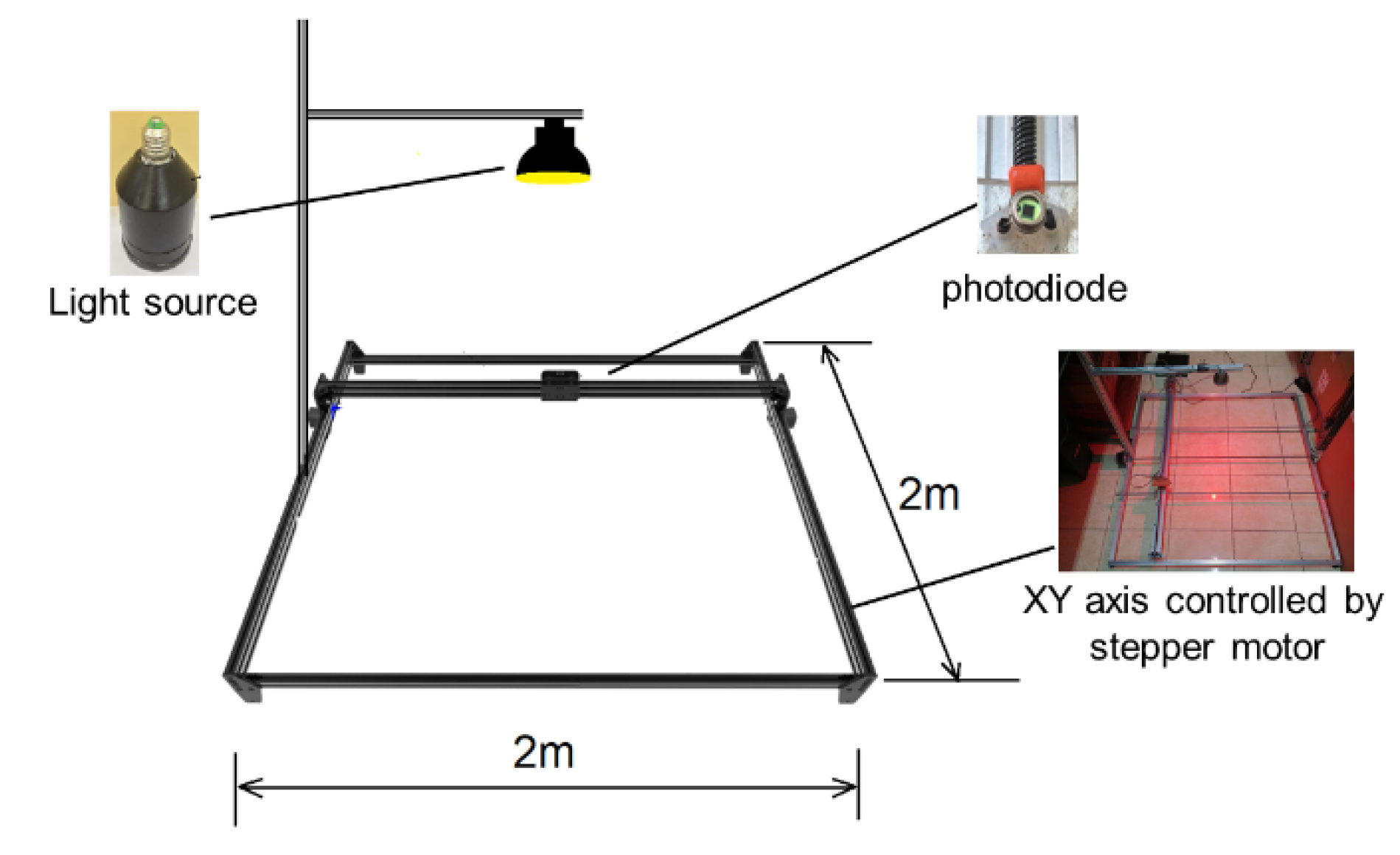
We made the optical distribution measurement system shown in Figure 13. Osram bpw21 photodiode [16] was used to collect optical energy from the light source, and this photodiode was located along the XY axis, which could be moved and controlled by computer. We made a program for the photodiode to sample at consecutive locations 4 cm apart. The measurement system had an area of 2 m × 2 m. So, the square detector system had 50 × 50 pixels. The value of the pixel ranged from 0 to 255 (8 bits analog to digital converter (ADC)), which quantitatively represents the intensity of light.
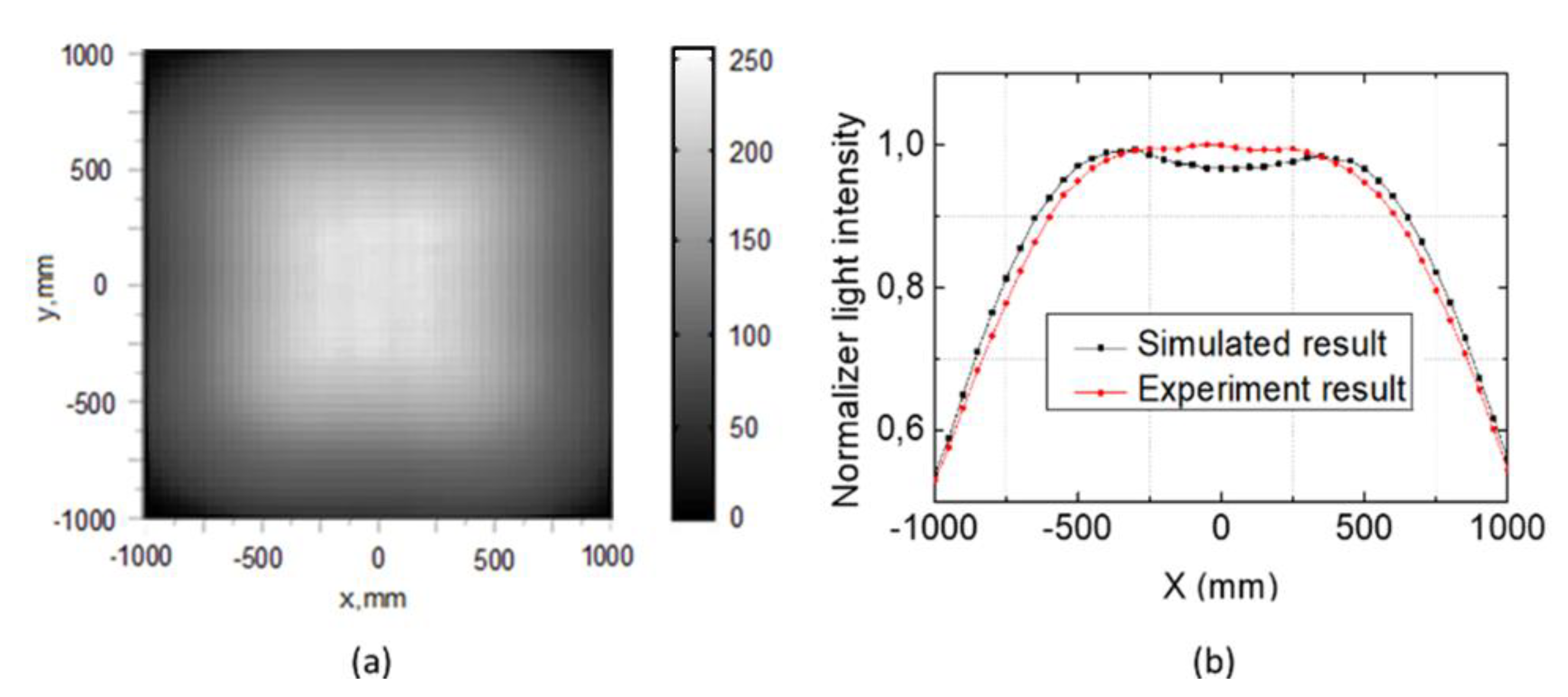
The simulated intensity and the measured intensity were normalized to compare simulation and test results. Figure 14 shown the Experiment results of the distribution measuring system. Figure 14a shows the measured optical distribution, and Figure 14b shows a comparison of the line distributions along the X axis across the center of the illuminated area.
Most of the linear distributions along the X axis for simulation and experiment results were consistent with each other. The experiment achieved a uniformity of 75% with a minimum value of 110 and maximum value of 243, where uniformity was calculated by Equation (2). The difference between simulation and test results can be explained by many factors. Firstly, the exact value of the PMMA refractive index could be different from the simulation. In addition, the size of the engraving tools may cause quality degradation. Creating lens morphologies may not entirely be accurate with this design. Increasing the accuracy of engraving tools helps to achieve a more precise morphology. However, studies have also shown that if an engraving tool is too small, it can deteriorate the quality of the work surface [11].
3.3. Outdoor Test
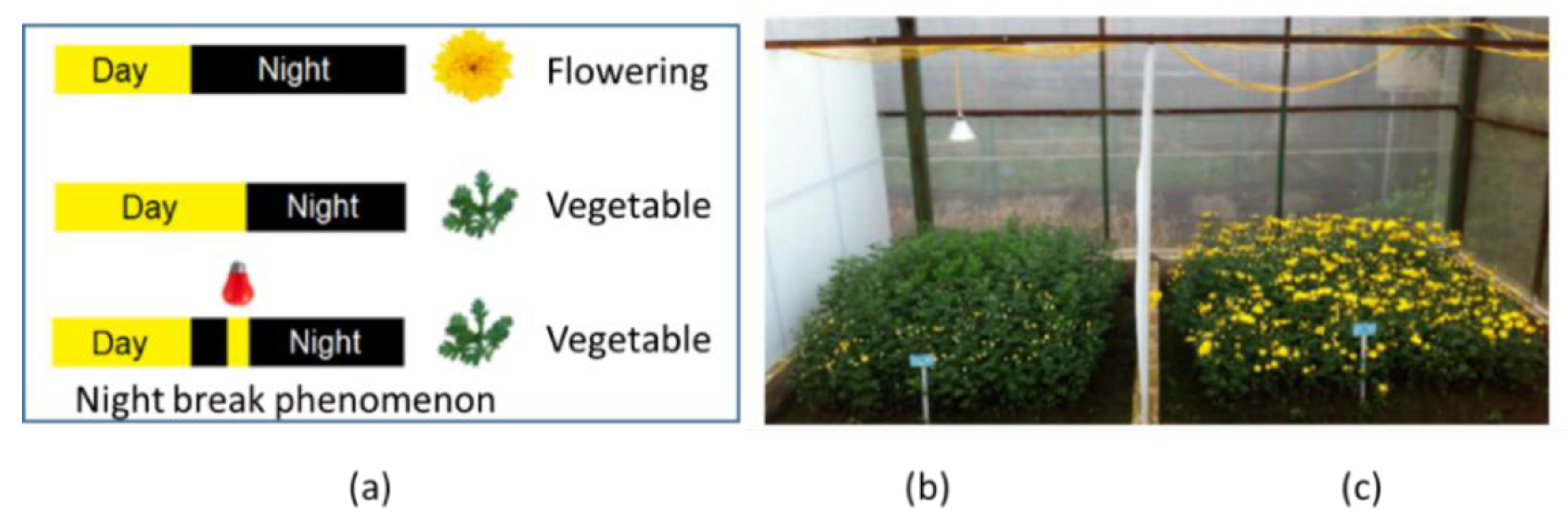
An LED with an optical component in this study was applied to control chrysanthemum flowering. Chrysanthemum is a short-day plant, which flowers only when the provided photoperiod is shorter than the “critical period” [17]. We used night break phenomenon [12] as show in Figure 15 to control chrysanthemum flowering. We made a short flash of light in the middle of the night so the plant would behave as if it had been exposed to a long day. The differences of chrysanthemum growth between controlled flowering and uncontrolled flowering are shown in Figure 15b and Figure 15c, respectively. When chrysanthemums were under uncontrolled flowering, it flowered at a time of no demand. Flower sizes were small, and the quality was also low. Chrysanthemums under controlled flowering had a longer vegetative process, resulting in taller chrysanthemums. With time-controlled flowering, the quality of the product improved.
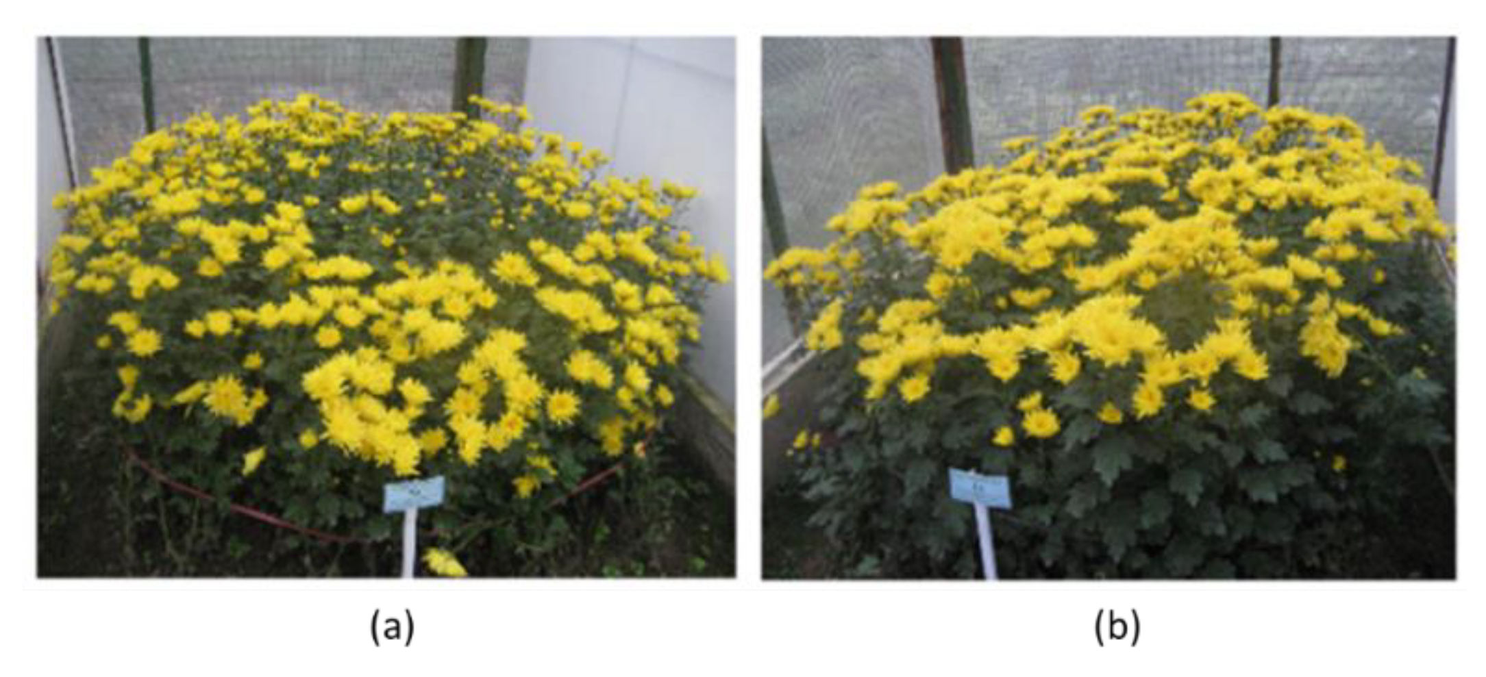
The flowering process takes 20 to 30 days after stopping the night break phenomenon. The wavelength that is suitable for illumination is 630 nm [18]. In this experiment, we used two flowerbeds of chrysanthemums. The first flowerbed was under a 5W COB LED with 630 nm wavelength with optical components we designed, and the second flowerbed was under the same LED with a traditional parabolic reflector. Chrysanthemums were illuminated at night with a projection time of 2 h per day, and the distance between stems was 10 × 16 cm. The area of the flowerbed was 4 m2 (2 × 2 m). Thus, 250 flowers were planted in each flowerbed. After two months, the results are shown in Figure 16.
As shown in Figure 16a, chrysanthemums under LED with parabolic reflectors had non-uniform heights; the plants on the edge of the area were shorter than the plants at the center, which results in a lower-quality commercial product. On the other hand, chrysanthemums under LED with our optical components showed quite uniform heights, which is important in the market. Specific numerical results are shown in Table 2.
Based on the data in Table 2, we can see that both samples had good results in controlled flowering; more than 94% of plants had no flowers before stopping the night break illumination. The LED with our optical components was better than the LED with a parabolic reflector for controlling the flowering effect in terms of uniformity in height. Also, the overall height of flowers under our light source was higher than those under the conventional LED source by 12%. The flower size was also 6% larger in our case.
A uniform light distribution on the cultivated area using our proposed design is a very promising solution in the field of high-value-added agriculture. Our method can be applied to many types of LEDs, reducing costs and achieving high efficiency.
4. Conclusions
In this paper, double linear Fresnel lenses made of PMMA with 20 grooves each were fabricated using high-speed CNC milling. The method of making the lenses demonstrated its capability for high-volume-based manufacturing. Design, simulation, fabrication, and measurement of double linear Fresnel lenses were discussed. The achieved uniformity of the redistributed irradiation was about 75%, which is consistent with the simulation result. An outdoor test of the performance of our design for agricultural lighting and a comparison between our light source and a conventional light source were conducted. It shows our proposed design exhibits great potential for commercialization.
Author Contributions
S.S.; T.Q.T., and N.H.V. proposed the ideas and designed the simulation and experiments. H.V. and N.M.K. performed simulations and experiments and analyzed the data. D.T.G. collected agricultural experiment results. All authors have read and agreed to the published version of the manuscript.
Funding
This research was funded by Vietnam Academy of Science & Technology under Grant Number QTKR01.01/18-19, National Science & Technology Program for Development of Center Highlands (Vietnam) under Grant Number TN18/C08 and Ministry of Science and Technology of Vietnam under Grant Number NĐT.46. KR/18.
Conflicts of Interest
The authors declare no conflicts of interest.
References
- Giang, D.T.; La, T.L.; Tien, T.Q.; Duong, P.H.; Tong, Q.C. A simple designed lens for human centric lighting using LEDs. Appl. Sci. 2020, 10, 1–9. [Google Scholar]
- Giang, D.T.; Pham, T.S.; Ngo, Q.M.; Nguyen, V.T.; Tien, T.Q.; Duong, P.H. An Alternative Approach for High Uniformity Distribution of Indoor Lighting LED. IEEE Photonics J. 2020, 12. [Google Scholar] [CrossRef]
- E. Fred Schubert Light-Emitting Diodes, 2nd editio; Cambridge University Press: Cambridge, UK, 2006.
- Ding, Y.; Liu, X.; Zheng, Z.; Gu, P. Freeform LED lens for uniform illumination. Opt. Express 2008, 16, 12958. [Google Scholar] [CrossRef] [PubMed] [Green Version]
- Wang, K.; Chen, F.; Liu, Z.; Luo, X.; Liu, S. Design of compact freeform lens for application specific light-emitting diode packaging. Opt. Express 2010, 18, 413. [Google Scholar] [CrossRef] [PubMed] [Green Version]
- Benı´tez, P. Simultaneous multiple surface optical design method in three dimensions. Opt. Eng. 2004, 43, 1489. [Google Scholar] [CrossRef]
- Miñano, J.C.; Benítez, P.; Liu, J.; Infante, J.; Chaves, J.; Wang, L. Applications of the SMS method to the design of compact optics. Opt. Model. Des. 2010, 7717, 77170I. [Google Scholar]
- Wang, G.; Wang, L.; Li, F.; Kong, D. Design of optical element combining Fresnel lens with microlens array for uniform light-emitting diode lighting. J. Opt. Soc. Am. A 2012, 29, 1877. [Google Scholar] [CrossRef] [PubMed]
- Yu, X.; Wei, X.; Zhang, O.; Zhang, X. Research on illumination uniformity of high-power LED array light source. AIP Conf. Proc. 2018, 1971. [Google Scholar] [CrossRef] [Green Version]
- Vu, N.H.; Pham, T.T.; Shin, S. LED uniform illumination using double linear fresnel lenses for energy saving. Energies 2017, 10, 2091. [Google Scholar] [CrossRef] [Green Version]
- Ries, H.; Rabl, A. Edge-ray principle of nonimaging optics. J. Opt. Soc. Am. A 1994, 11, 2627. [Google Scholar] [CrossRef]
- Shimomachi, T. Effect of Night Break Treatment on Growth and Flowering in. Metab. Clin. Exp. 2011, 8521, 303–308. [Google Scholar]
- Lens by LED. Available online: https://www.ledlink-optics.com/lens/ (accessed on 6 March 2020).
- High Speed CNC Milling. Available online: https://www.proxxon.com/en/micromot/27110.php (accessed on 6 March 2020).
- Blalock, T.; Medicus, K.; DeGroote Nelson, J. Fabrication of freeform optics. Opt. Manuf. Test. XI 2015, 9575, 95750H. [Google Scholar]
- BPW 21-Photodiode. Available online: https://www.osram.com/ecat/Metal Can® TO39 Ambient Light Sensor BPW 21/com/en/class_pim_web_catalog_103489/global/prd_pim_device_2219533/ (accessed on 18 April 2020).
- Higuchi, Y. Florigen and anti-florigen: Flowering regulation in horticultural crops. Breed. Sci. 2018, 68, 109–118. [Google Scholar] [CrossRef] [PubMed] [Green Version]
- Tripathi, S.; Hoang, Q.T.N.; Han, Y.J.; Kim, J. Il Regulation of photomorphogenic development by plant phytochromes. Int. J. Mol. Sci. 2019, 20, 6165. [Google Scholar] [CrossRef] [PubMed] [Green Version]
Figure 1.
The principle of our proposed uniform LED illumination system.

Figure 2.
Structure of LED illumination system composed of an LED chip, collimator, and double linear Fresnel lenses.
Figure 2.
Structure of LED illumination system composed of an LED chip, collimator, and double linear Fresnel lenses.

Figure 3.
Illustration of collimator using in this research: (a) Principles of Total Internal Reflection (TIR) lens; (b) A commercial collimator lens.
Figure 3.
Illustration of collimator using in this research: (a) Principles of Total Internal Reflection (TIR) lens; (b) A commercial collimator lens.

Figure 4.
Design method of linear Fresnel lens (a) A single linear Fresnel lens redistributes light to a receiver. (b) Design for a segment of a linear Fresnel lens. (c) The lights were spread in two dimensions by double Fresnel lenses.
Figure 4.
Design method of linear Fresnel lens (a) A single linear Fresnel lens redistributes light to a receiver. (b) Design for a segment of a linear Fresnel lens. (c) The lights were spread in two dimensions by double Fresnel lenses.

Figure 5.
The flowchart of the design process of the linear Fresnel lens.

Figure 6.
The simulation parameters using LighttoolsTM software.

Figure 7.
Simulation performance of collimator lens: (a) light distribution of output beam; (b) viewing angle of LED with collimator at 1.2°; and (c) ray tracing of LED with collimator.
Figure 7.
Simulation performance of collimator lens: (a) light distribution of output beam; (b) viewing angle of LED with collimator at 1.2°; and (c) ray tracing of LED with collimator.

Figure 8.
Light distribution on an LED receiver using a collimator and double linear Fresnel lenses.
Figure 8.
Light distribution on an LED receiver using a collimator and double linear Fresnel lenses.

Figure 9.
Illustration of the simulation structure for loss analysis and ray-tracing analysis.

Figure 10.
Light distribution on a receiver with (a) dT = 2°; (b) dT=3°; and (c) dT=4°. (d) Efficiency and uniformity depend on deflection angle dT.
Figure 10.
Light distribution on a receiver with (a) dT = 2°; (b) dT=3°; and (c) dT=4°. (d) Efficiency and uniformity depend on deflection angle dT.

Figure 11.
Light distribution on a receiver with (a) dθ = 2°; (b) dθ = 4°; and (c) dθ = 6°. (d) Efficiency and uniformity depend on the angle of the collimated beam.
Figure 11.
Light distribution on a receiver with (a) dθ = 2°; (b) dθ = 4°; and (c) dθ = 6°. (d) Efficiency and uniformity depend on the angle of the collimated beam.

Figure 12.
Photograph of the fabricated linear Fresnel lenses.

Figure 13.
Experimental setup of light distribution measurements.

Figure 14.
Experiment results of the distribution measuring system. (a) Distribution on the target surface. (b) Comparison of the simulation and experiment distribution along the X axis across the center of the target surface.
Figure 14.
Experiment results of the distribution measuring system. (a) Distribution on the target surface. (b) Comparison of the simulation and experiment distribution along the X axis across the center of the target surface.

Figure 15.
Night break phenomenon (a) Principle; (b) Chrysanthemum with controlled flowering by LED. (c) Chrysanthemum without controlled flowering.
Figure 15.
Night break phenomenon (a) Principle; (b) Chrysanthemum with controlled flowering by LED. (c) Chrysanthemum without controlled flowering.

Figure 16.
Chrysanthemums under controlled flowering (a) By LED with a parabolic reflector. (b) By LED with our optical component.
Figure 16.
Chrysanthemums under controlled flowering (a) By LED with a parabolic reflector. (b) By LED with our optical component.


Table 1.
The double Fresnel lenses design parameters.
| Design Parameters | |
|---|---|
| Type of LED | COB |
| Type of collimator | TIR |
| Refractive index of the Fresnel lens | 1.49 |
| Thickness of the Fresnel lens | 5 mm |
| Number of grooves of the Fresnel lens | 20 |
| Diameter of the Fresnel lens | 100 mm |
Table 2.
Results of chrysanthemums after 2 months of testing.
| Parameter | LED with Double Fresnel Lenses | LED with Parabolic Reflector |
|---|---|---|
| Number of stems surveyed Rate of early flowering | 216 4.2% | 207 5.9% |
| Lowest height of the stems | 75 cm | 58 cm |
| Highest height of the stems | 84 cm | 80 cm |
| Average height of the stems | 82 cm | 72 cm |
| Average diameter of the flower | 7.8 cm | 7.3 cm |
© 2020 by the authors. Licensee MDPI, Basel, Switzerland. This article is an open access article distributed under the terms and conditions of the Creative Commons Attribution (CC BY) license (http://creativecommons.org/licenses/by/4.0/).
Share and Cite
MDPI and ACS Style
Vu, H.; Kieu, N.M.; Gam, D.T.; Shin, S.; Tien, T.Q.; Vu, N.H. Design and Evaluation of Uniform LED Illumination Based on Double Linear Fresnel Lenses. Appl. Sci. 2020, 10, 3257. https://0-doi-org.brum.beds.ac.uk/10.3390/app10093257
AMA Style
Vu H, Kieu NM, Gam DT, Shin S, Tien TQ, Vu NH. Design and Evaluation of Uniform LED Illumination Based on Double Linear Fresnel Lenses. Applied Sciences. 2020; 10(9):3257. https://0-doi-org.brum.beds.ac.uk/10.3390/app10093257
Chicago/Turabian StyleVu, Hoang, Ngoc Minh Kieu, Do Thi Gam, Seoyong Shin, Tran Quoc Tien, and Ngoc Hai Vu. 2020. "Design and Evaluation of Uniform LED Illumination Based on Double Linear Fresnel Lenses" Applied Sciences 10, no. 9: 3257. https://0-doi-org.brum.beds.ac.uk/10.3390/app10093257
Note that from the first issue of 2016, this journal uses article numbers instead of page numbers. See further details here.