Safety Assessment of Masonry Arch Bridges Considering the Fracturing Benefit


Department of Structural, Geotechnical and Building Engineering, Politecnico di Torino, 24 Corso Duca degli Abruzzi, 10129 Torino, Italy
*
Author to whom correspondence should be addressed.
Appl. Sci. 2020, 10(10), 3490; https://0-doi-org.brum.beds.ac.uk/10.3390/app10103490
Submission received: 9 April 2020
/
Revised: 30 April 2020
/
Accepted: 6 May 2020
/
Published: 18 May 2020
(This article belongs to the Section Civil Engineering)
Abstract
:Featured Application
The study of the fracturing process provides an accurate and effective whole service life assessment of masonry arch bridges, and more in general, for a great number of historical masonry structures still having strategic or heritage importance in the infrastructure system.
Abstract
The evolutionary analysis of the fracturing process is an effective tool to assess of the structural bearing capacity of masonry arch bridges. Despite their plain basic assumptions, it must be remarked that elastic analysis and plastic or limit analysis can hardly be used to describe the response and predict damage for moderate or service load levels in masonry arch bridges. Therefore, a fracture mechanics-based analytical method with elastic-softening regime for masonry is suitable in order to study the global structural behaviour of arch bridges, highlighting how the arch thrust line is affected by crack formation, and the maximum admissible load evaluated by means of linear elastic fracture mechanics is larger than the load predicted by elasticity theory. Such an increment in terms of bearing capacity of the arch bridge can be defined “fracturing benefit”, and it is analogous to the “plastic benefit” of the plastic limit analysis. The fracturing process, which takes into account the fracture initiation and propagation in the masonry arch bulk, occurs before the set-in of the conditions established by means of the plastic limit analysis. In the present paper, the study of the elastic-fracture-plastic transitions is performed for three monumental masonry arch bridges with different shallowness and slenderness ratios. This application returns an accurate and effective whole service life assessment of masonry arch bridges, and more in general it can be suitable for a great number of historical masonry structures still having strategic or heritage importance in the infrastructure systems.
1. Introduction
The essential structural shape of masonry bridges has been strikingly constant throughout the civilized world, from Roman times through the medieval European period up to nowadays [1]. As long as the Roman Empire lasted, bridge building was closely connected to the personality of the head of the Roman army, known as the Pontifex Maximus, or chief bridge builder [2]. It is interesting to note that, with time, this title passed from the Roman emperors to the head of the Roman Catholic church, who is supposed to be the chief builder of bridges connecting Earth and heaven.
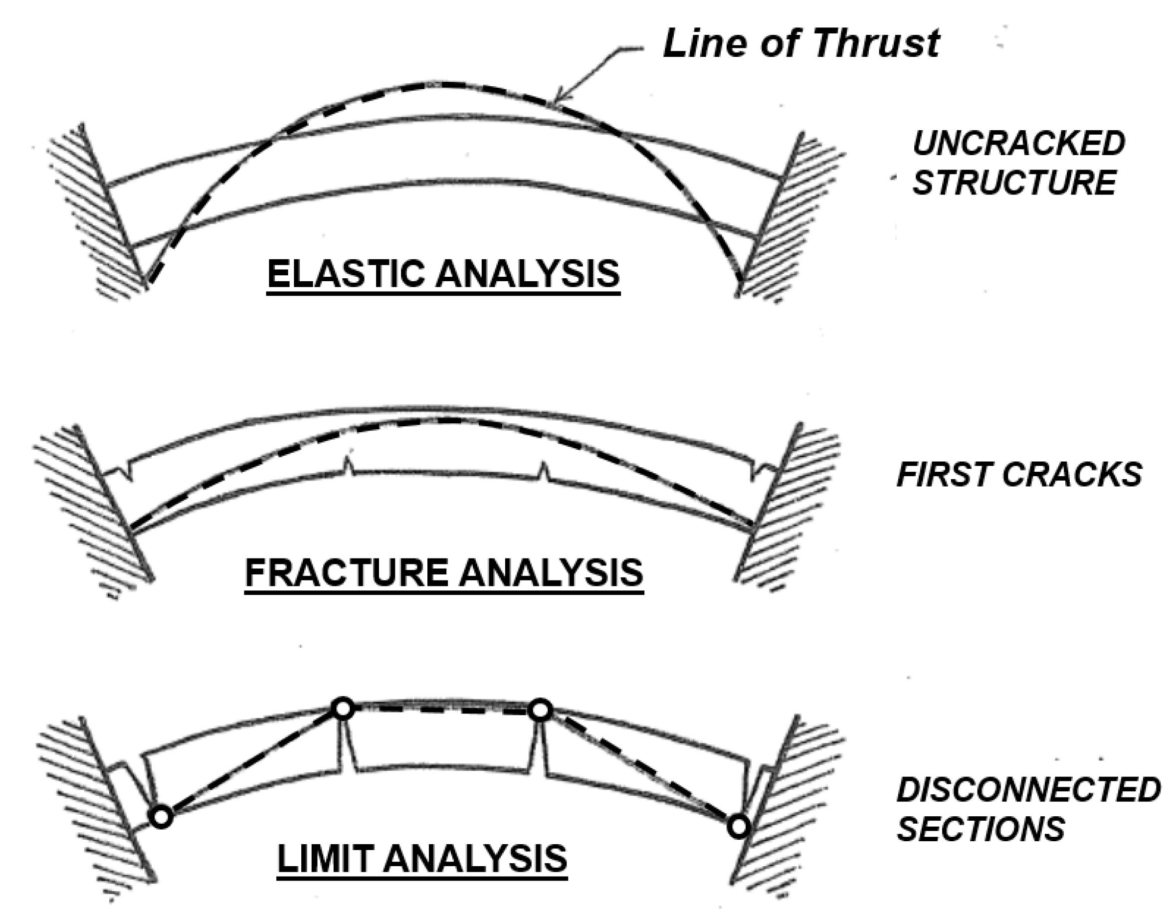
Later, during 19th and 20th centuries, the Ecole Nationale des Ponts et Chaussées in Paris formalized the structural principles at the base of the masonry arch bridge shape [3,4]. These structural principles are based on the fundamental concept of line of thrust (Figure 1).
The line of thrust, or line of pressure, can be defined as the set of lines of action of the successive resultant forces acting on a structure, or rather, that act as internal constraint reactions, proceeding from one end to the other of the structure itself [5]. If we imagine constructing an arch that presents exactly the form of the pressure line, thus the bending moment vanishes at each point of the arch. Between one section and another, only a compressive force would then be transmitted, as the internal reaction is always tangential to the axis of the curved beam. This is the situation that tends to occur when non-tensile resistant materials are used, as for masonry bridges.
Within elasticity theory, the distribution of stresses at the interfaces between masonry arch segments is proved to be function of the line of thrust. Classically, as masonry is supposed to be non-tensile resistant, the resulting pressure line has to lie within the central kern of the arch cross-section in order to prevent tension [6].
On the other hand, by means of the plastic analysis [7] the notions mentioned above are further simplified by the understanding that the arch limit condition can be represented by a thrust line superimposed on the whole arch structure, and that the plastic condition is described by that thrust line being everywhere inscribed within the arch [8]. In spite of its plain basic assumptions, it must be remarked that plastic or limit analysis can hardly be used to describe the response and predict damage for moderate or service load levels in masonry arch bridges (Figure 1), not leading to their limit condition [9].
Considering the aforesaid structural theories, a conceptual need arises, considering the damaging process, i.e., cracks initiation and growth between elastic and collapse mechanisms formation, in order to provide a better prediction of the actual behavior of masonry arch bridges [10,11].
In the present work, the evolutionary analysis of the fracturing process is highlighted as an effective tool to assess the structural bearing capacity of masonry arch bridges. By means of damage assessment, this evolutionary analysis shows how the arch thrust line is affected by crack formation, and how the maximum admissible load evaluated by means of linear elastic fracture mechanics (LEFM) is greater than the load predicted by elasticity theory. Such an increment in terms of bearing capacity of the arch bridge can be defined “fracturing benefit”, and it is analogous to the “plastic benefit” of the limit analysis. The fracturing process, taking into account crack initiation and propagation in the masonry arch bulk, occurs before the set-in of the conditions established by means of the plastic limit analysis. The study of the elastic-fracture-plastic transitions (Figure 1) returns an accurate and effective whole service life assessment of masonry arch bridges, and more in general for a great number of historical masonry structures still having strategic or heritage importance in the infrastructure systems.
2. Masonry Arch Off-Center Compression: LEFM Based Approach
In order to highlight the LEFM-based approach to the dominant problem concerning the off-center compression in masonry arches, the definition of the concept of stress concentration has to be compared with the more conceptual one of stress intensification. Whereas the former concept represents the amplification of the stress applied to a body, which occurs at the tip of a notch, the latter measures the severity of this amplification in the case where, instead of the notch, there is a sharp crack, as usually in the case of a masonry structure, and the amplification itself tends to infinity at the crack tip [12,13].
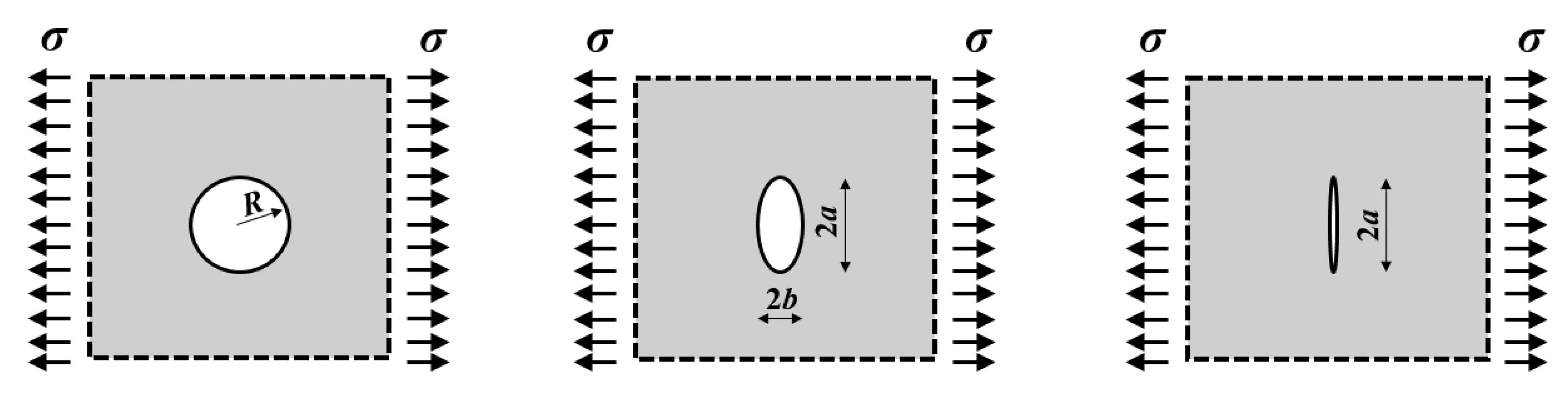
For the sake of clarity, let us consider the following cases in terms of stress concentration vs. stress intensification (Figure 2): (i) structural plate weakened by circular hole; (ii) structural plate notched by elliptical hole; (iii) structural plate having a rectilinear crack. Let us consider that each structure is subjected to a tensile stress, σ, applied from outside, orthogonally to the straight line to which the crack or the notch belongs.
As it is well known from elasticity theory, if the notches are relatively small in comparison with the size of the corresponding structural plate, the failure point is reached for external stresses, σ, that have the value of σ = σu/3, where σu is the material strength, in the case of circular holes [14], and the value of in the case of elliptical holes, with the major semi-axis, a, and the minor semi-axis, b (Figure 2). Following the elastic formulation of Inglis [15], when the elliptical hole tends to represent a crack, i.e., when the stress concentration factor 1 + 2a/b tends to infinity, the failure point becomes σ = 0, then no stresses can be applied to the damaged structure.
For this reason, the concept of stress concentration must be overcome in order to take into account the structural damage, and, in the case of a plate structure weakened by an internal crack (Figure 2), the fracture point is a function of an amplification factor, the so-called stress-intensity factor, KI, which is a real measure of crack opening severity. When KI reaches its critical value, KIC, the crack propagates. Considering the plate structure weakened by an internal crack [16], the stress intensification following LEFM [17,18] is represented by:
and, therefore, the critical condition becomes:
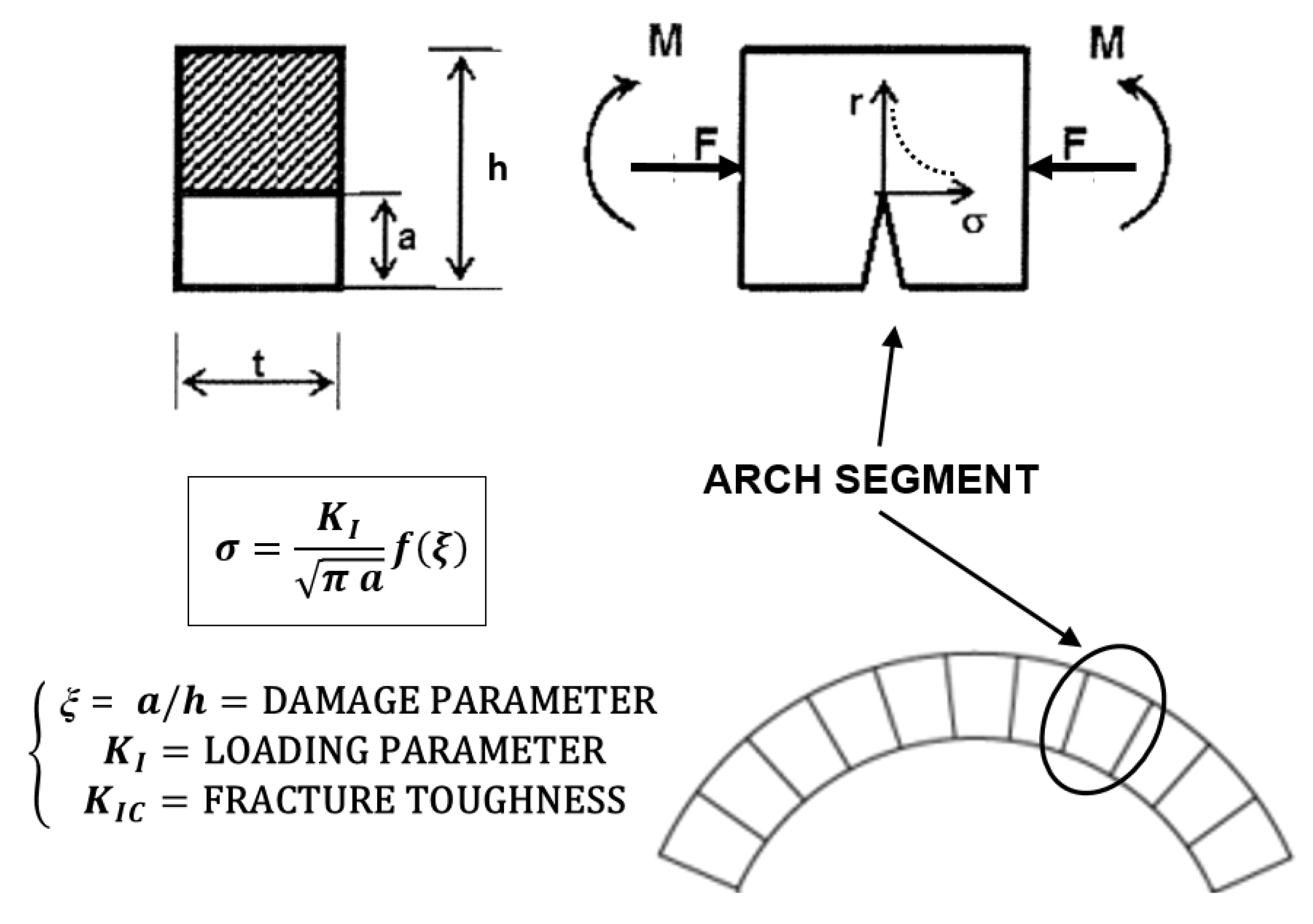
The possibility of generalizing this reasoning to geometries different from the abovementioned academic ones is very important, as in the case of an arch subjected to off-center compression (Figure 3). Note that, for certain structural geometries and loading conditions, the process of crack propagation is unstable, in the sense that once a certain critical load is reached, the crack propagates spontaneously and without further increments in load, as at first considered by Griffith [16].
On the other hand, there are cases in which crack propagation is first stable and then unstable, or, vice versa, first unstable and then stable. Among the latter there is the case of the eccentric compression of a cracked beam of rectangular cross section (Figure 3; [19]). This case, explained below, can represent in an effective way the static regime of an arch segment subjected to axial force and bending moment [20,21,22].
As it is well known from linear elastic fracture mechanics [23], a bending moment, M (Figure 3), induces a stress-intensity factor at the crack tip equal to:
while a tensile axial force, F, induces the factor:
where ξ = a/h is the relative crack depth, and the so-called weight functions, YM and YF, for a relative crack depth 0 ≤ ξ ≤ 0.7, are [23]: YM(ξ) = 6 (1.99ξ1/2 − 2.47ξ23/2 + 12.97ξ5/2 − 23.17ξ7/2 + 24.80ξ9/2) and YF(ξ) = 1.99ξ1/2 − 0.41ξ23/2 + 18.70ξ5/2 − 38.48ξ7/2 + 53.85ξ9/2.
When the axial force, F, is a compression and the bending moment, M, tends to open the crack, as generally happens at the cross sections of arch-structures, the total stress-intensity factor representing the loading parameter can be obtained by applying the superposition principle:
where e denotes the eccentricity of the equivalent eccentric axial force.
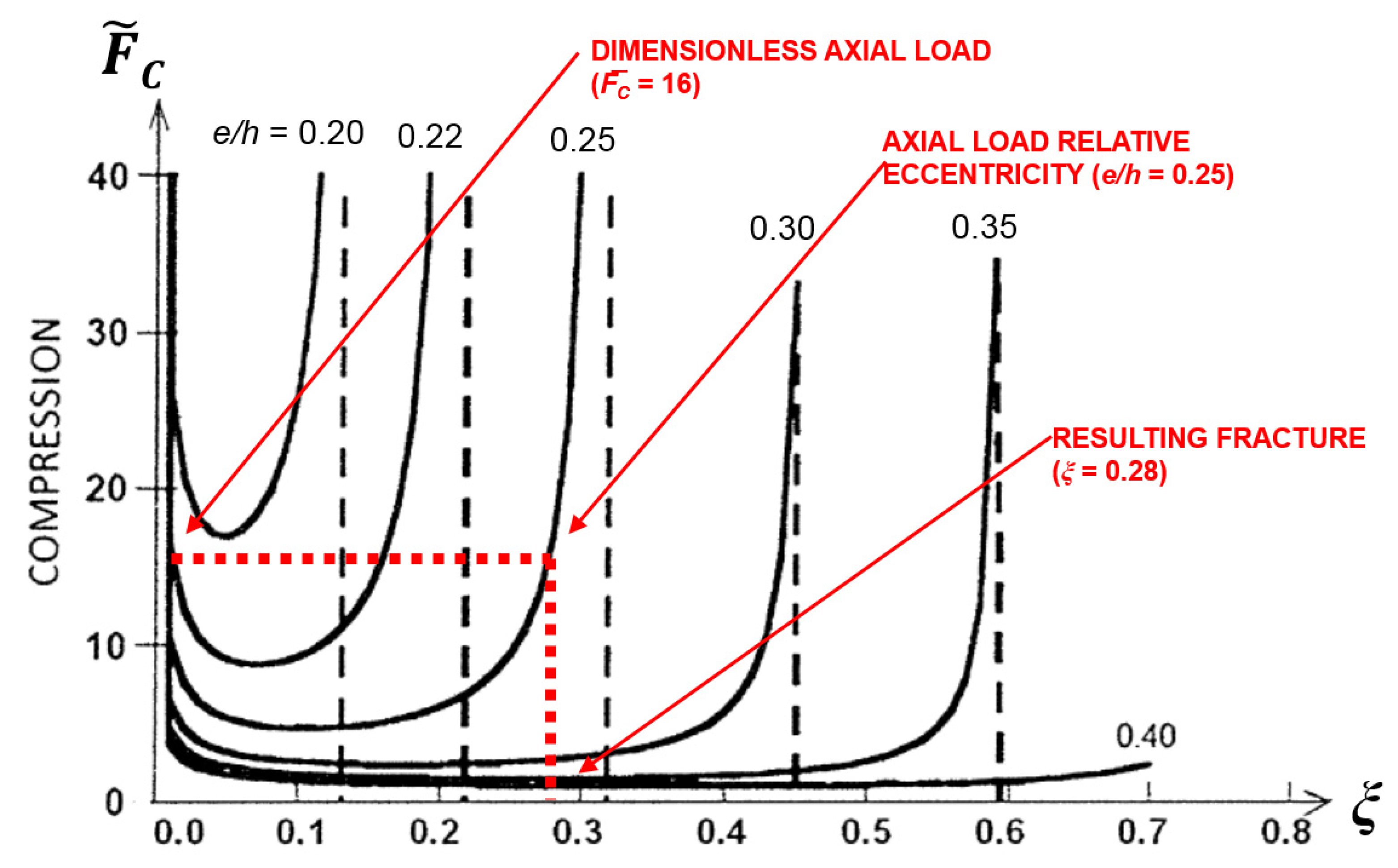
From the critical condition of crack propagation, i.e., when the loading parameter reaches the fracture toughness, KI = KIC, the dimensionless axial force of crack extension can be obtained, as a function of the relative crack depth, ξ, and as the relative eccentricity e/h of the load varies:
The curves of Figure 4 graphically represent the arch-structure fracturing process (Equation (6)), and show how, with the eccentricity e/h fixed, fracturing reaches a stable stage only after presenting an unstable one. If the load F does not have the possibility of following the unstable descending branch of the curve e/h = constant, fracturing will display a catastrophic behavior and the representative point in the diagram of Figure 4 will advance horizontally to meet up again with the curve e/h = constant on its stable branch. In Figure 4, an example of mechanism of crack opening for off-center compression is shown: starting from a dimensionless axial force, , equal to 16, and a relative eccentricity of the axial force, e/h, equal to 0.25, the corresponding relative crack depth in the cross-section is found as ξ = 0.28.
It is moreover important to consider that, for each relative crack depth, ξ, a relative eccentricity, e/h, exists, under which the crack closes again, at least partially [19,24]. From the closing condition, KI = 0, we have:
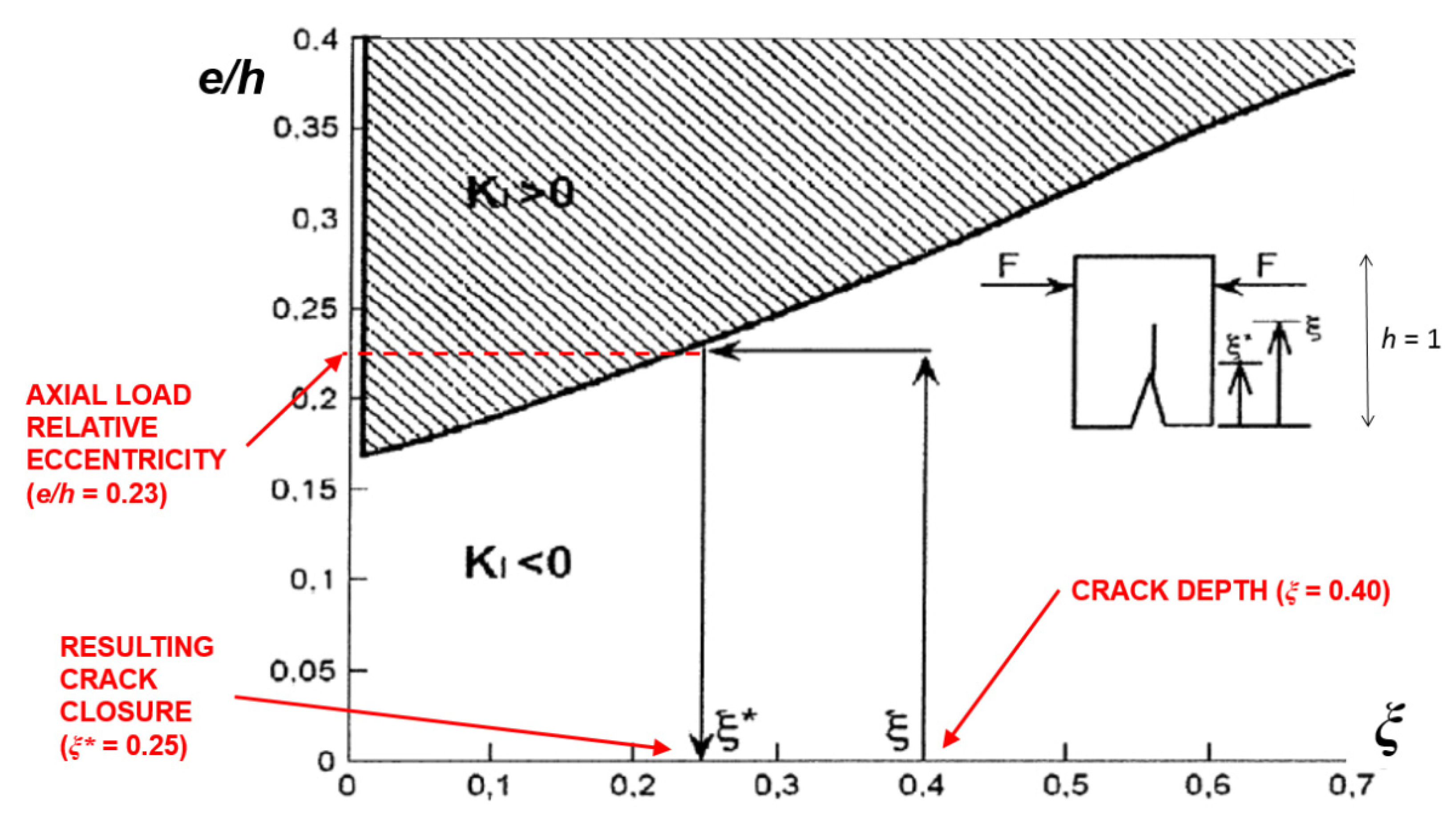
The curve of Figure 5 graphically represents Equation (7). The points under the curve represent arch-structure cracks and loading conditions for which KI < 0, i.e., the condition of crack closure. In Figure 5, an example of mechanism of crack closure for off-center compression is shown: starting from an arch cross-section with a crack depth equal to ξ = 0.40, and subjected to an off-center compression with a relative eccentricity of the axial force e/h = 0.23, it returns a crack closure corresponding to ξ* = 0.25.
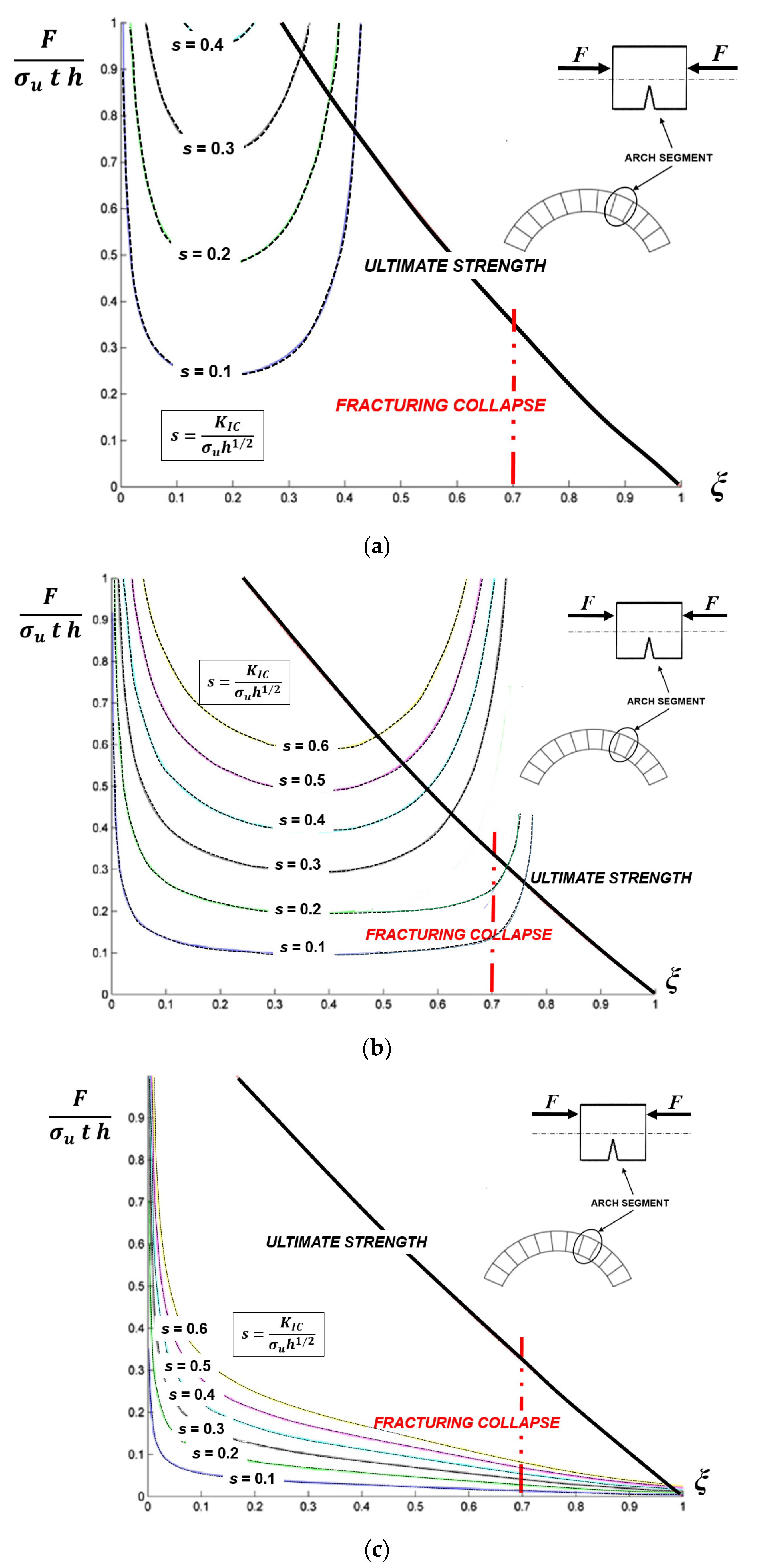
Moreover, a LEFM-based approach to the analysis of masonry arches can take into account scale effects [12,25,26,27], that are always present in structural engineering due to the different physical dimensions of two mechanical parameters of the materials: strength, σu, and fracture toughness, KIC. The former is related to the plastic or ultimate strength collapse, whereas the latter is related to the brittle crack propagation. The competition between the two collapses of different nature in masonry arches can easily be shown by considering Equation (5), for the critical condition KI = KIC [20]. Considering the arch cross section subjected to off-center compression, if both members of Equation (5) are divided by σu h1/2, where σu is the masonry compressive strength, we obtain:
where s is a dimensionless parameter, the so-called brittleness number [13], which allows one to measure the scale-dependent susceptibility of fractures to propagate in unstable condition, .
On the other hand, it is possible to consider the non-dimensional load of ultimate strength in the arch cross-section of depth h-ξ:
Equations (8) and (9) are plotted in Figure 6 as functions of the normalized crack depth, ξ, and different values of relative eccentricity of the axial force, e/h. While the former produces a set of curves by varying brittleness number, s, the latter is represented by a unique curve [20].
Note that, in the arch cross-section, crack propagation collapse is possible only if the value ξ = 0.7 is reached, i.e., the crack depth damages at least 70% of section height [28]: graphically, this means that fracturing collapse occurs only if the curve plotted from Equation (8) reaches ξ = 0.7 before intercepting the curve of ultimate strength (Equation (9)).
In Figure 6a, with e/h = 0.15, it is evident that for low values of relative eccentricity of the axial force, i.e., for small bending moments, the ultimate strength collapse at the arch ligament precedes and obscures crack propagation collapse for each brittleness number s: all the curves representing the arch structural behaviours intercept the ultimate strength limit before reaching the fracturing collapse condition ξ = 0.7.
In Figure 6c, with e/h = 0.35, it is evident that for high values of relative eccentricity of the axial force, i.e., for large bending moments, the crack propagation collapse precedes ultimate strength collapse at the arch ligament for each brittleness number s: all the curves representing the structural behaviours of the arch intercept the fracturing collapse, ξ = 0.7, before reaching the ultimate strength limit (thick curve).
In the intermediate cases (Figure 6b), 0.15 ≤ e/h ≤ 0.35, the ultimate strength collapse at the arch ligament precedes crack propagation collapse when the brittleness number, s, shows higher values, i.e., when the arch structure presents high fracture toughness, low ultimate strength, and/or small structural size.
3. Masonry Arch Bridge Assessment: Elastic-Fracture-Plastic Transitions
Elastic and plastic analyses, currently exploited in order to evaluate the behaviour of arch or vault structures, often leave some doubts in the engineering practice. Elastic analysis, specifically Mery’s method, is applicable to arch structures when the line of thrust lies within the inertial core of the arch cross-section, in order to prevent the onset of detrimental tensile stresses. Mery’s studies, dating back to 1840, gained widespread recognition in the field of arch structures design: his method was based on the use of a graphic procedure in order to check the thrust line in agreement with the stress limitations identified by the theory of elasticity [29].
On the other hand, plastic theory, specifically the limit analysis, was firstly defined by Heyman [7] for masonry arch assessment. In his work, Heyman investigated arch structures using the principles of plastic design developed originally for steel frames. He applied in detail these principles to the analysis of the structural system of the gothic cathedral. The formation of a plastic hinge in masonry arches is acknowledged right where the thrust line is tangent to the arch edges. Three tangent points lead to the formation of three hinges: the limit to trigger a kinematic collapse mechanism generally lies in the formation of a fourth hinge [8].
Starting from these assumptions, none of the previous two analyses can capture the intermediate static regimes characterised by damage (see Figure 1): in other words, the elastic analysis describes the structure until the first non-linearity arises, whereas the plastic analysis defines the last condition of an arch structure before the final collapse occurs [10]. A more sophisticated analytical method is therefore needed, that allows the fracturing process between the elastic regime and the final collapse to be manifest [11].
In this context, a fracture mechanics-based analytical method with elastic-softening regime for masonry is suitable in order to study the global structural behaviour of masonry arches [19,20,21,22]. An elastic-softening constitutive law for masonry is taken into account, exploiting an elastic constitutive law coupled with a fracturing process based on LEFM. As a matter of fact, crack initiation and growth in an arch structure with elastic-softening behaviour can influence the position of the line of thrust, redistributing the internal stresses similarly to an elastic-plastic structure when affected by the formation of plastic hinges [30]. In this way, the evolutionary analysis of fracturing processes assesses how the arch structural behaviour is affected by cracks formation, as well as by the internal stress redistribution, clarifying how the maximum admissible load evaluated by means of LEFM is larger than the load predicted by elasticity theory. Such an increase in terms of maximum admissible load can be defined “fracturing benefit”, and it is analogous to the “plastic benefit” of the plastic limit analysis. On the other hand, the arch structure final condition determined by plastic analysis, i.e., the four hinges kinematic chain (Figure 1), can be foreseen by a fracture mechanics point of view: namely, while an uncracked cross-section of the arch structure carries out an internal action of perfectly fixed joint, a cracked cross section carries out an internal action of elastically fixed joint [19]. Such a stiffness loss can be represented by the so-called “brittle hinge” [11,21,30].
In the following, a comparison between elastic, plastic and fracture analyses of the structural behaviour of three monumental masonry arch bridges having different shallowness and slenderness ratios is performed. The purpose of the comparison is to highlight the different values of the maximum live load prior to failure that can be achieved using the three abovementioned analyses, with particular focus on the position of brittle hinges simulating the cracks, and the plastic ones triggering the kinematic collapse.
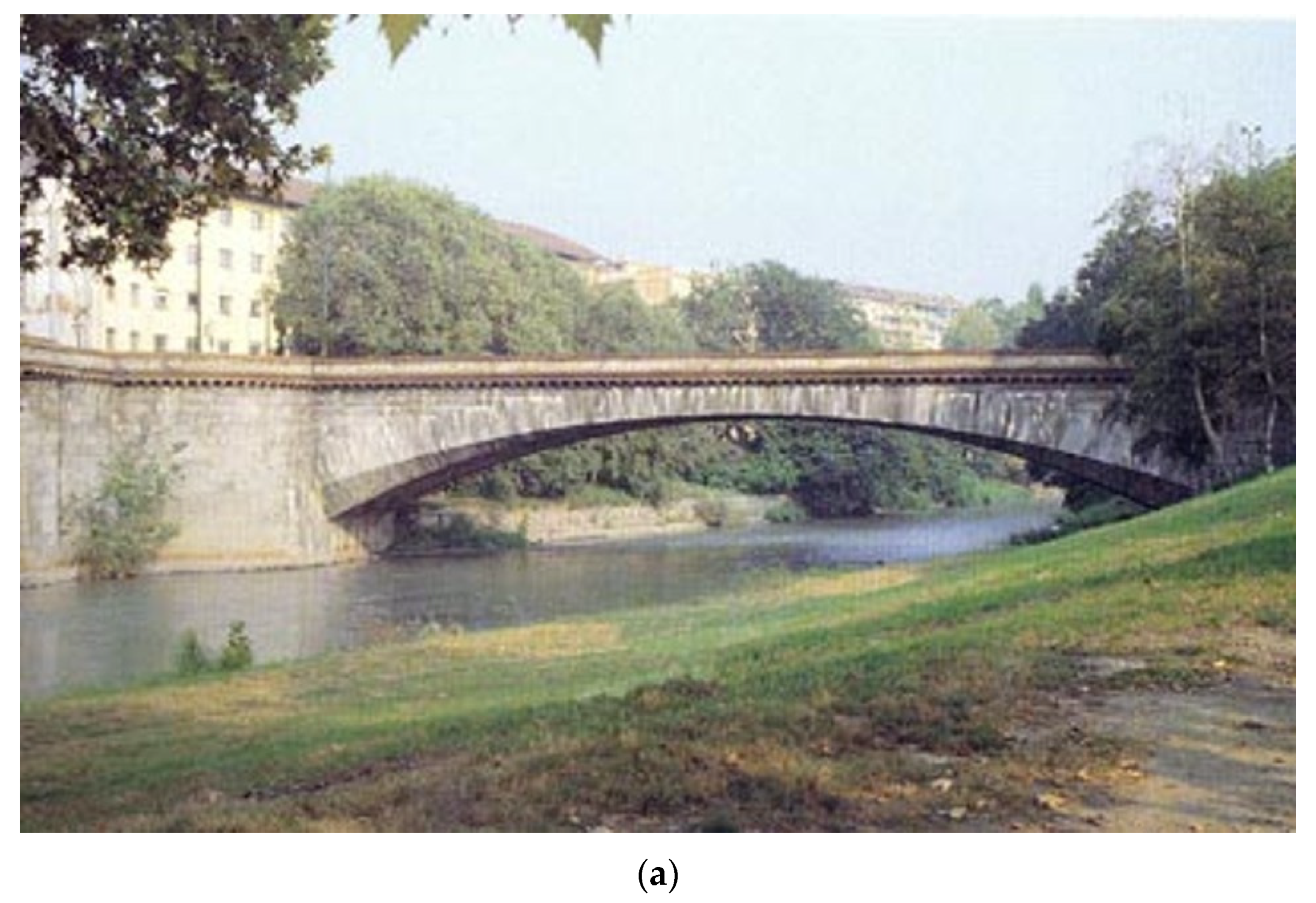
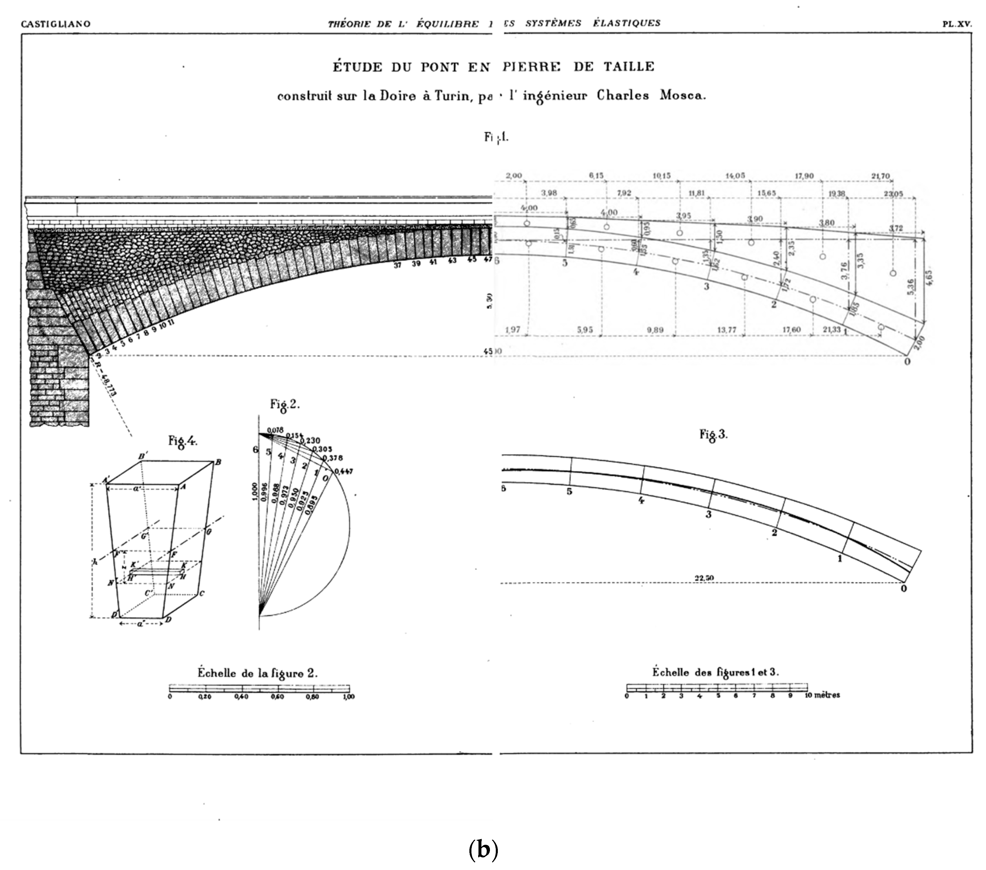
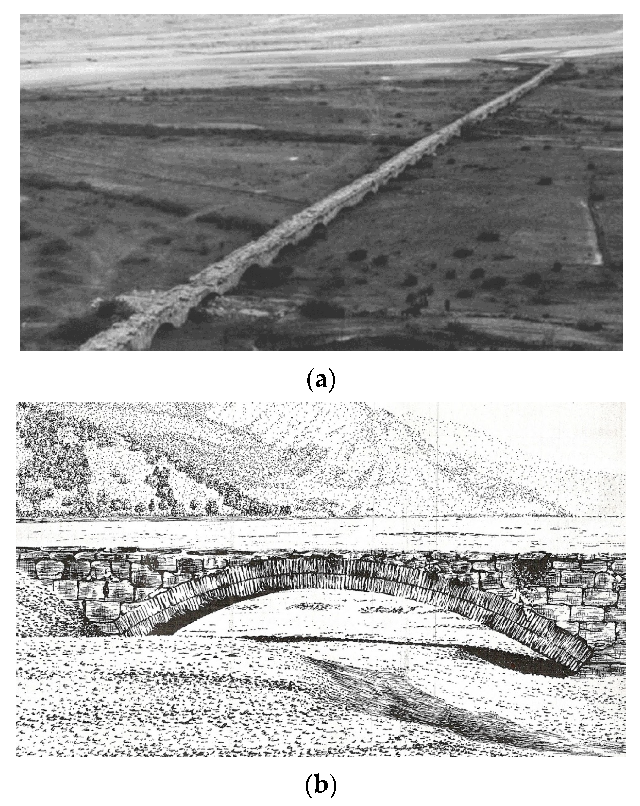
The first case study refers to the Mosca bridge, located in Turin, Italy (Figure 7). The Mosca bridge is the most daring construction built in Turin in the first half of the XIXth century. The total length of the arch bridge is 129 m, and its width is 13.7 m.
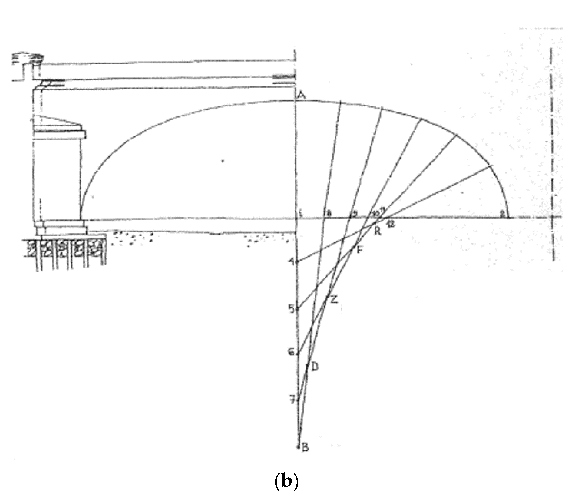
The principal structure, entirely cut in stone, is a single shallow arch of 45 m in length, with a rise of 5.5 m, and a depth of 1.5 m. The impressive arch structure shallowness ratio results to be 1/8. The structural material of the arch structure is Malanaggio stone, a greenish-gray gneiss with mechanical characteristics similar to those of granite. It was extracted from the main quarry of Malanaggio, near Turin [32]. The main geometrical and mechanical characteristics of the Mosca bridge are reported in Table 1.
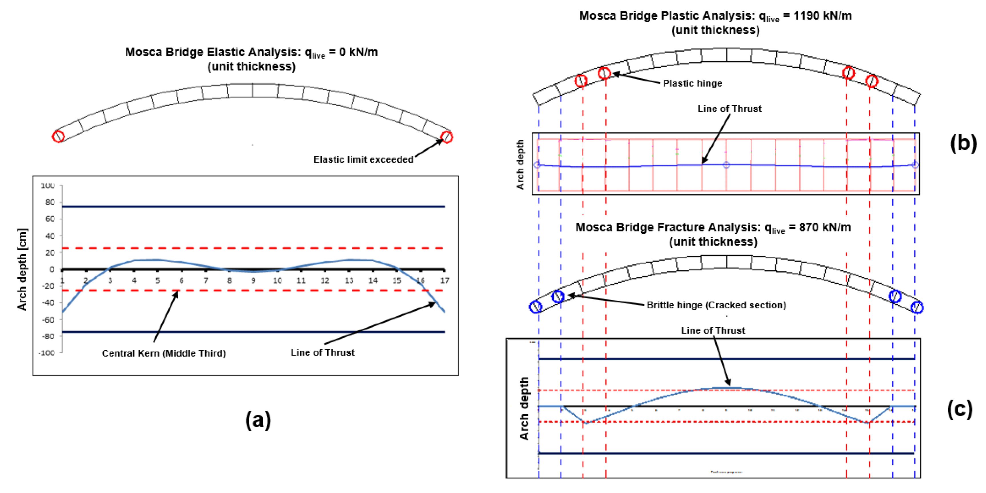
The purpose of the comparison between the three above mentioned analyses is to obtain the elastic-fracture-plastic transitions in terms of maximum live load, as uniformly distributed over the whole bridge deck, and the position of the critical sections representing both the brittle hinges and cracks within the fracture analysis, or the plastic hinges within the limit analysis. In Figure 8, the elastic-fracture-plastic transitions are shown.
A Mosca bridge elastic analysis (Figure 8a) presents a line of thrust outside the central kern (middle third) for a uniformly distributed live load equal to zero, since tensile stresses in the masonry arise immediately. The elastic limit is overtaken in the two arch section at the springings. In Figure 8a, red circles represent the points where the line of thrust exceeds the middle third of the arch cross section.
Limit analysis (Figure 8b) shows that the uniformly distributed maximum live load affordable by the arch structure is 1190 kN/m, a value for which the masonry compressive strength in four points is reached. In these positions, although the line of thrust results to be within the arch volume, plastic hinges (red circles in Figure 8b) due to compressive failure take places triggering the kinematic collapse of the arch bridge.
On the other hand, fracture analysis (Figure 8c) allows the uniformly distributed live load to reach the maximum value of qlive = 870 kN/m. Note that the positions of the cracked sections, the so-called brittle hinges [21,30], are identified by means of the abovementioned fracture mechanics approach, considering the damaging mechanisms (Figure 4 and Figure 5) in a step-by-step loading process. In particular, for qlive = 5 kN/m, two cracks of length ξ = 0.2, i.e., a = 30 cm, appear at the springings. Then, increasing the live load to 20 kN/m, the fracturing processes at the springings present a crack closure (Figure 5) equal to ξ* = 0.03, i.e., a * = 4.5 cm, which remains stable until four cross-sectional failures (blue circles in Figure 8c) due to compression in the arch ligament arise at qlive = 870 kN/m. For these reasons, the positions of the brittle hinges (cracked cross-sections) differ from those of the plastic hinges due to the fact that the real fracturing process is taken into account. Note that the aforesaid crack closure condition entailed a re-centering of the line of thrust, resulting in an improved bearing capacity of the arch structure. The total fracturing benefit computed by fracture analysis points out an increase in the arch bearing capacity from null value to 870 kN/m.
As a second case study, the structural behavior of the Limyra bridge is described. The Limyra bridge is a late Roman monumental arch bridge located in the ancient protectorate of Lycia, in modern West Turkey (Figure 9), and it represents one of the oldest and longest segmental arch bridges in the world, spanning over a length of 360 m on 26 shallow arch structures [33]. This monumental bridge, crossing over the Alakır river, connected the ancient cities of Limyra and Pamphylia, along the imperial road of Lycia. Before its restoration, the bridge had been totally sunken in alluvial soils for years, and only a few spans were accessible.
The main geometrical and mechanical characteristics of the Limyra Bridge are reported in Table 1. Also for this case study, the elastic-fracture-plastic transitions return an effective comparison about the different values of maximum live load, as uniformly distributed over the whole bridge deck, and the positions of the critical sections representing the brittle hinges (cracks) within the fracture analysis, or the plastic hinges within the limit analysis (Figure 10).
A Limyra bridge elastic analysis (Figure 10a) presents a line of thrust outside the central kern (middle third) for a uniformly distributed live load equal to zero, since tensile stresses in the masonry arise immediately. The elastic limit is overtaken in the two arch section at the springings, suddenly concluding the elastic analysis. In Figure 10a, red circles represent the points where the line of thrust exceeds the middle third of the arch cross section.
Limit analysis (Figure 10b) shows that the uniformly distributed maximum live load affordable for the arch structure is 3490 kN/m, a value for which the masonry compressive strength in four points is reached. In these positions, plastic hinges (red circles in Figure 10b) due to compressive failure take place triggering the kinematic collapse of the arch bridge. Also in this case, the line of thrust remains within the arch volume, the ultimate structural behavior of the arch being characterized solely by the masonry compressive strength.
On the other hand, fracture analysis (Figure 10c) allows the uniformly distributed live load to reach the value of qlive = 480 kN/m, for which four cracked arch sections, or brittle hinges, appear (blue circles in Figure 10c). In particular, for the maximum live load qlive = 480 kN/m, in the abovementioned four cross-sections the crack length ξ = 0.7, i.e., a = 70 cm, is reached, leading to the fracturing failure due to the complete inefficiency of the arch ligament. In this case, the compressive stress level in the arch ligament for the four cracked cross-sections is lower than 10 MPa, whereas the masonry compressive strength is equal to 50 MPa. Therefore, a consistent fracturing process is taken into account, contrary to what is accomplished by plastic analysis. Finally, the fracturing benefit here computed points out an increase in the arch bearing capacity from null value to 480 kN/m.
The last case study object of this work is related to the Vittorio Emanuele I bridge, erected in Turin by Napoleon’s government after 1810 (Figure 11). Initially known as the “Stone bridge”, after the return of the Savoy royal family to Turin in 1814, it was renamed “Vittorio Emanuele I bridge”, the name that it still retains. At the time of its construction, this monumental arch bridge constituted the main entrance to Turin from Genoa and its harbor [32].
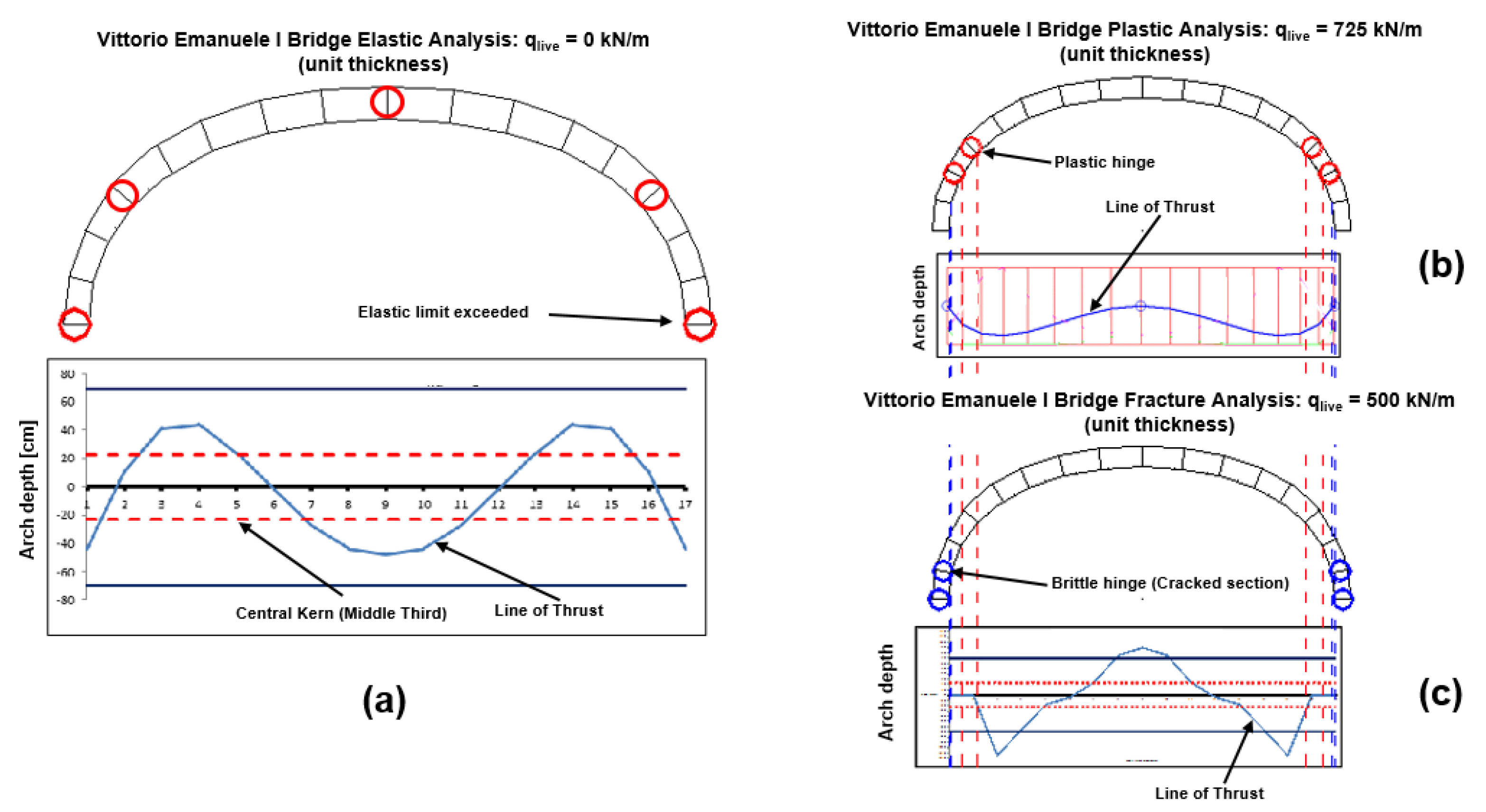
The main geometrical and mechanical characteristics of the Vittorio Emanuele I bridge are reported in Table 1, whereas the elastic, plastic, and fracture analyses results are summarized in Figure 12.
An elastic analysis (Figure 12a) returns a null value of the uniformly distributed live load, the arch structure showing the line of thrust outside the middle third for the most part of the bridge span.
On the contrary, limit analysis (Figure 12b) allows the live load to reach the value of 725 kN/m. However, for this value, the compressive strength of the masonry is exceeded in four points (plastic hinges), the line of thrust remaining within the arch bulk. Also for the Vittorio Emanuele I bridge, the line of thrust remains within the arch volume for the whole bridge span, the ultimate structural behavior being characterized solely by the masonry compressive strength.
The analysis of the fracturing process of the Vittorio Emanuele I arch structure (Figure 12c) returns a maximum live load qlive = 500 kN/m, when the formation of four cracked sections is acknowledged, triggering the global cracking failure of the bridge. In particular, up to qlive = 350 kN/m, two cracks of length ξ = 0.1, i.e., a = 10 cm, characterize the springing ligaments. Then a complete crack closure (Figure 5; ξ * = 0.0) sets in, with a consequent re-centering of the line of thrust, and four cross-sectional failures (blue circles in Figure 12c) take place at qlive = 500 kN/m, due to high compression stress in the arch ligament. Also for the Vittorio Emanuele I bridge, a consistent fracturing process is taken into account for the arch structure, complying with the crucial need of a more accurate global assessment of the load carrying capacity of masonry bridges.
Moreover, a comparison between the structural behaviours shown by the three analyzed bridges leads to the following comments. The three ultimate structural behaviours appear to be very diversified in terms of damage mechanisms and maximum live loads affordable by the three arch structure. This is due to the fact that the three bridges present two different main geometrical characteristics affecting the structural behavior: the arch shallowness ratio, and the arch depth (see Table 1). The Mosca bridge shows a shallowness ratio equal to 1/8 and arch depth of 1.5 m, whereas Limyra bridge is less shallow (1/5 in shallowness ratio) but thinner (1.0 m in arch depth). It has been demonstrated above that when the arch structure is more shallow, it tends to assume the ultimate structural behavior of a rectilinear beam, showing its cracked sections at the abutements (see Mosca bridge, Figure 8c). On the contrary, when the arch is less shallow, it tends to assume the structural behavior of a round arch (shallowness ratio: 1/2) with the cracked sections at the haunches (see Limyra bridge, Figure 10c). Furthermore, besides the different shallowness ratios, Mosca bridge and Limyra bridge show also a difference for the second main geometrical parameter: the arch depth, which contributes to the arch ultimate bearing capacities, in addition to the mechanical parameters of the masonry. With an arch depth equal to 1.5 m, the Mosca bridge shows an ultimate bearing capacity of 870 kN/m2, whereas the Limyra bridge, whose arch depth is 1.0 m, offers an ultimate capacity of 480 kN/m2. Finally, the structure characterising the Vittorio Emanuele I bridge presents a different type of arch shape: a polycentric arch (see Figure 11b). For this arch structure, high compression stresses arises at the springings, where crushing failures affect the cross-sections. Furthermore, the ultimate bearing capacity of the arch structure, 500 kN/m2, results to be function of the arch depth (1.0 m) that is comparable to that of the Mosca bridge.
Generally speaking, from the point of view of the fracture analysis, the fracturing benefit computed for the three arch bridges points out an increase in the ultimate bearing capacity from a null value to 870 kN/m2 for the Mosca bridge, to 480 kN/m2 for the Limyra bridge, and to 500 kN/m2 for the Vittorio Emanuele I bridge. On the other hand, from the point of view of the safety assessment, the aforesaid ultimate capacities are largely consistent with the international load model for road bridges [35]: considering Load Model 1, and the dispersal of concentrated load equal to 1.0 m in depth, we obtain a uniformly distributed load value equal to 600/(4 × 4) + 9 = 46.5 kN/m2. This characteristic value is widely recovered by the computed bearing capacities of the Mosca bridge, Limyra bridge, and Vittorio Emanuele I bridge.
Lastly, it is shown that the structural behavior of a masonry arch bridge is strongly affected by crack formation, as well as the internal stress redistribution following to the repositioning of the line of thrust. The arch damaging process, which takes place when the conditions assessed through theory of elasticity are no longer valid, and before the set-in of the conditions established by means of plastic analysis, involves fractures initiation and propagation, which are often not easily detectable along the bridge span. In particular, the problem of recognizing on site an incipient damaging process at the arch springings is not easy to approach, due to the fact that, in these positions, the damage arises at the arch extrados, hided by the filling. In this case, the on-site damage detection could be effectively performed by acoustic emission structural monitoring [36,37]. This non-destructive technique, coupled with the abovementioned fracture analysis, can return a thorough whole service life assessment of masonry arch bridges [38].
4. Conclusions
Despite of their plain basic assumptions, it must be remarked that elastic analysis and plastic or limit analysis can hardly be used to describe the response and predict damage for moderate or service load levels in masonry arch bridges. Therefore, a fracture mechanics-based analytical method with elastic-softening regime for masonry is suitable in order to study the global structural behaviour of arch bridges, highlighting how the thrust line trend is affected by cracks formation, as well as by the internal stress redistribution. In particular, the maximum admissible load for masonry arch bridges evaluated by means of linear elastic fracture mechanics is greater than the load predicted by elasticity theory. Such an increment in terms of bearing capacity of the arch bridge can be defined “fracturing benefit”, and it is analogous to the “plastic benefit” of the limit analysis. The fracturing process, that takes into account the fracture initiation and propagation in the masonry arch bulk, occurs before the set-in of the conditions established by means of the plastic limit analysis. The study of the elastic-fracture-plastic transitions returns an accurate and effective whole service life assessment of masonry arch bridges, and more in general for a great number of historical masonry structures still having strategic or heritage importance in the infrastructure systems.
Author Contributions
Conceptualization, F.A.; methodology, G.L.; software, F.A.; validation, G.L.; formal analysis, F.A.; investigation, F.A.; resources, G.L.; data curation, G.L.; writing—original draft preparation, F.A.; writing—review and editing, G.L.; visualization, F.A.; supervision, G.L. All authors have read and agreed to the published version of the manuscript.
Funding
This research received no external funding.
Acknowledgments
The authors gratefully acknowledge Eng. Diego Randazzo for his effective support.
Conflicts of Interest
The authors declare no conflict of interest.
Symbols
| a = crack length |
| h = arch depth |
| t = arch thickness |
| KI = stress intensity factor |
| YM, YF = weight functions of the stress intensity factor KI |
| KIC = Fracture Toughness |
| ξ = a/b = relative crack depth |
| ξ* = relative crack closure |
| F = axial force acting on the arch cross-section |
| M = bending moment acting on the arch cross-section |
| e = M/F = eccentricity of the axial force F with respect to the cross-section center of gravity |
| = dimensionless axial force of crack extension |
| σu = material strength |
| s = KIC/(σu h1/2) = brittleness number |
References
- Wallsgrove, J. The aesthetics of loadbearing masonry arch bridges. Arch Bridges 1995, 1, 3–10. [Google Scholar]
- Lancaster, L.C. Concrete Vaulted Construction in Imperial Rome: Innovations in Context; Cambridge University Press: Cambridge, UK, 2005. [Google Scholar]
- Becchi, A. The statics of arches between France and Italy. Proc. First Int. Congr. Constr. Hist. 2003, 1, 353–364. [Google Scholar]
- Kurrer, K.E. The History of the Theory of Structures. From Arch Analysis to Computational Mechanics; Ernst & Sohn: Berlin, Germany, 2008. [Google Scholar]
- Carpinteri, A. Structural Mechanics Fundamentals; CRC Press: Boca Raton, FL, USA, 2013. [Google Scholar]
- Block, P.; De Jong, M.J.; Ochsendorf, J.A. As hangs the flexible line: Equilibrium of masonry arches. Nexus Netw. J. 2006, 8, 9–19. [Google Scholar] [CrossRef] [Green Version]
- Heyman, J. The stone skeleton. Int. J. Solids Struct. 1966, 2, 255–296. [Google Scholar] [CrossRef]
- Boothby, T.E. Analysis of Masonry Arches and Vaults. Prog. Struct. Eng. Mater. 2001, 3, 246–256. [Google Scholar] [CrossRef]
- Roca, P.; Cervera, M.; Gariup, G.; Pelà, L. Structural Analysis of Masonry Historical Constructions. Classical and Advanced Approaches. Arch. Comput. Methods Eng. 2010, 17, 299–325. [Google Scholar] [CrossRef] [Green Version]
- Foce, F.; Aita, D. The Masonry Arch Between «Limit» and «Elastic» Analysis. A Critical Re-Examination of Durand-Claye’s Method. In Proceedings of the 1st International Congress on Construction History, Madrid, Spain, 20–24 January 2003; Volume 1, pp. 895–908. [Google Scholar]
- Moreira, V.N.; Fernandes, J.; Matos, J.C.; Oliveira, D.V. Reliability-based assessment of existing masonry arch railway bridges. Constr. Build. Mater. 2016, 115, 544–554. [Google Scholar] [CrossRef]
- Barenblatt, G.I. Flow, Deformation and Fracture; Cambridge University Press: Cambridge, UK, 2014. [Google Scholar]
- Carpinteri, A. Notch sensitivity in fracture testing of aggregative materials. Eng. Fract. Mech. 1982, 16, 467–481. [Google Scholar] [CrossRef]
- Kirsch, E.G. Die Theorie der Elastizität und die Bedürfnisse der Festigkeitslehre. Z. Ver. Dtsch. Ing. 1898, 42, 797–807. [Google Scholar]
- Inglis, C.E. Stresses in Plates Due to the Presence of Cracks and Sharp Corners. Trans. Inst. Naval Archit. 1913, 55, 219–241. [Google Scholar]
- Griffith, A.A. The phenomena of rupture in solids. Philos. Trans. R. Soc. 1921, A221, 163–198. [Google Scholar]
- Muskhelishvili, N.I. Some Basic Problems of the Mathematical Theory of Elasticity (in Russian). In Proceedings of the USSR Academy of Sciences, Leningrad, 4th ed.; Noordhoff: Groningen, The Netherlands, 1933. (In English) [Google Scholar]
- Westergaard, H.M. Bearing pressures and cracks. J. Appl. Mech. 1939, 6, 49–53. [Google Scholar]
- Carpinteri, A.; Lacidogna, G.; Accornero, F. Evolution of the fracturing process in masonry arches. J. Struct. Eng. 2015, 141, 04014132. [Google Scholar] [CrossRef]
- Accornero, F.; Lacidogna, G.; Carpinteri, A. Evolutionary fracture analysis of masonry arches: Effects of shallowness ratio and size scale. Comptes Rendus Mécanique 2016, 344, 623–630. [Google Scholar] [CrossRef]
- Accornero, F.; Lacidogna, G.; Carpinteri, A. Medieval arch bridges in the Lanzo Valleys, Italy: Incremental structural analysis and fracturing benefit. J. Bridge Eng. 2018, 23, 05018005. [Google Scholar] [CrossRef]
- Lacidogna, G.; Accornero, F. Elastic, plastic, fracture analysis of masonry arches: A multi-span bridge case study. Curved Layer. Struct. 2018, 5, 1–9. [Google Scholar] [CrossRef]
- Tada, H.; Paris, P.C.; Irwin, G.R. The Stress Analysis of Crack Handbook; Paris Productions: St. Louis, MI, USA, 1985. [Google Scholar]
- Carpinteri, A.; Accornero, F. Residual crack opening in fiber-reinforced structural elements subjected to cyclic loading. Strength Fract. Complex. 2020, 12, 63–74. [Google Scholar] [CrossRef]
- Carpinteri, A. Scaling laws and renormalization groups for strength and toughness of disordered materials. Int. J. Solids Struct. 1994, 31, 291–302. [Google Scholar] [CrossRef]
- Carpinteri, A.; Accornero, F. Rotation versus curvature fractal scaling in bending failure. Phys. Mesomech. 2019, 22, 46–51. [Google Scholar] [CrossRef]
- Accornero, F.; Rubino, A.; Carpinteri, A. Ductile-to-brittle transition in fiber-reinforced concrete beams: Scale and fiber volume fraction effects. Mater. Des. Process. Commun. 2020, 1–11. [Google Scholar] [CrossRef] [Green Version]
- UIC. Recommendations for the Assessment of the Load Carrying Capacity of Existing Masonry and Mass-Concrete Arch Bridges (Code 778-3); International Union of Railways (UIC): Paris, France, 1995. [Google Scholar]
- Brencich, A.; Morbiducci, R. Masonry Arches: Historical Rules and Modern Mechanics. Int. J. Archit. Herit. 2007, 1, 165–189. [Google Scholar] [CrossRef]
- Taylor, N.; Mallinder, P. The brittle hinge in masonry arch mechanisms. Struct. Eng. 1993, 71, 359–366. [Google Scholar]
- Castigliano, A. Théorie de l’Equilibre des Systèmes Elastiques et ses Applications; Del Negro: Turin, Italy, 1879. [Google Scholar]
- Re, L. Bridges of Turin; Edizioni Centro Studi Piemontesi: Turin, Italy, 2019. (In Italian) [Google Scholar]
- O’Connor, C. Roman Bridges; Cambridge University Press: Cambridge, UK, 1993. [Google Scholar]
- Limyra Bridge. Available online: https://kantaratlas.blogspot.com/2018/02/limyra-bridge.html (accessed on 4 April 2020).
- EN 1991-2. Eurocode 1: Actions on Structures-Part 2: Traffic Loads on Bridges; CEN: Brussels, Belgium, 2003. [Google Scholar]
- Carpinteri, A.; Lacidogna, G.; Accornero, F. Fluctuations of 1/f noise in damaging structures analyzed by Acoustic Emission. Appl. Sci. 2018, 8, 1685. [Google Scholar] [CrossRef] [Green Version]
- Carpinteri, A.; Lacidogna, G.; Corrado, M.; Di Battista, E. Cracking and crackling in concrete-like materials: A dynamic energy balance. Eng. Fract. Mech. 2016, 155, 130–144. [Google Scholar] [CrossRef]
- Han, Q.; Xu, J.; Carpinteri, A.; Lacidogna, G. Localization of acoustic emission sources in structural health monitoring of masonry bridge. Struct. Control Health Monit. 2015, 22, 314–329. [Google Scholar] [CrossRef]
Figure 1.
Elastic-fracture-plastic transitions in masonry arches: softening and fracturing process.

Figure 2.
Transition from stress concentration (circular and elliptical hole) to stress intensification (crack).
Figure 2.
Transition from stress concentration (circular and elliptical hole) to stress intensification (crack).

Figure 3.
Arch segment subjected to off-center compression.

Figure 4.
Mechanism of crack opening for off-center compression (arch-structure fracturing process): case of an axial force corresponding to = 16, with a relative eccentricity e/h = 0.25, leading to a relative crack depth in the cross-section ξ = 0.28 (dotted line).
Figure 4.
Mechanism of crack opening for off-center compression (arch-structure fracturing process): case of an axial force corresponding to = 16, with a relative eccentricity e/h = 0.25, leading to a relative crack depth in the cross-section ξ = 0.28 (dotted line).

Figure 5.
Crack closing condition for off-center compression (arch-structure crack closure): case of an arch cross-section with a crack depth equal to ξ = 0.40, and subjected to an off-center compression with e/h = 0.23, which returns a crack closure corresponding to ξ* = 0.25.
Figure 5.
Crack closing condition for off-center compression (arch-structure crack closure): case of an arch cross-section with a crack depth equal to ξ = 0.40, and subjected to an off-center compression with e/h = 0.23, which returns a crack closure corresponding to ξ* = 0.25.

Figure 6.
Scale effects in masonry arch structures: Dimensionless load of brittle crack propagation versus normalized crack depth, ξ, for e/h = 0.15 (a); e/h = 0.20 (b); e/h = 0.35 (c).
Figure 6.
Scale effects in masonry arch structures: Dimensionless load of brittle crack propagation versus normalized crack depth, ξ, for e/h = 0.15 (a); e/h = 0.20 (b); e/h = 0.35 (c).

Figure 7.
Mosca Bridge, Turin (Italy): Overview (a); Arch sketch by Alberto Castigliano, 1879 [31] (b).
Figure 7.
Mosca Bridge, Turin (Italy): Overview (a); Arch sketch by Alberto Castigliano, 1879 [31] (b).


Figure 8.
Mosca bridge: (a) Elastic, (b) plastic, and (c) fracture analyses.

Figure 9.
Limyra bridge (Turkey): Overview (a); Single arch sketch (b) [34].
Figure 9.
Limyra bridge (Turkey): Overview (a); Single arch sketch (b) [34].

Figure 10.
Limyra Bridge: (a) Elastic, (b) plastic, and (c) fracture analyses.

Figure 11.
Vittorio Emanuele I Bridge, Turin (Italy): Overview (a); Sketch of the polycentric arch (b).
Figure 11.
Vittorio Emanuele I Bridge, Turin (Italy): Overview (a); Sketch of the polycentric arch (b).


Figure 12.
Vittorio Emanuele I bridge: (a) Elastic, (b) plastic, and (c) fracture analyses.


Table 1.
Geometrical and mechanical parameters of the analyzed arch bridges.
| Arch Bridge | Arch Span (m) | Shallowness Ratio (-) | Arch Depth (cm) | Slenderness Ratio (-) | Young Modulus (MPa) | Masonry Density (kN/m3) | Compressive Strength (MPa) | Tensile Strength (MPa) | Fracture Toughness (daN/cm3/2) |
|---|---|---|---|---|---|---|---|---|---|
| Mosca | 45 | 1/8 | 150 | 1/30 | 50,000 | 25 | 50 | 1.5 | 100 |
| Limyra | 10 | 1/5 | 100 | 1/10 | 30,000 | 18 | 30 | 1.0 | 70 |
| Vittorio Emanuele I | 25 | 1/3 | 100 | 1/25 | 50,000 | 25 | 50 | 1.5 | 100 |
© 2020 by the authors. Licensee MDPI, Basel, Switzerland. This article is an open access article distributed under the terms and conditions of the Creative Commons Attribution (CC BY) license (http://creativecommons.org/licenses/by/4.0/).
Share and Cite
MDPI and ACS Style
Accornero, F.; Lacidogna, G. Safety Assessment of Masonry Arch Bridges Considering the Fracturing Benefit. Appl. Sci. 2020, 10, 3490. https://0-doi-org.brum.beds.ac.uk/10.3390/app10103490
AMA Style
Accornero F, Lacidogna G. Safety Assessment of Masonry Arch Bridges Considering the Fracturing Benefit. Applied Sciences. 2020; 10(10):3490. https://0-doi-org.brum.beds.ac.uk/10.3390/app10103490
Chicago/Turabian StyleAccornero, Federico, and Giuseppe Lacidogna. 2020. "Safety Assessment of Masonry Arch Bridges Considering the Fracturing Benefit" Applied Sciences 10, no. 10: 3490. https://0-doi-org.brum.beds.ac.uk/10.3390/app10103490
Note that from the first issue of 2016, this journal uses article numbers instead of page numbers. See further details here.