Detection of Parking Slots Based on Mask R-CNN

Department of Vehicle Engineering, Jiangsu University, Zhenjiang 212013, China
*
Author to whom correspondence should be addressed.
Appl. Sci. 2020, 10(12), 4295; https://0-doi-org.brum.beds.ac.uk/10.3390/app10124295
Submission received: 31 May 2020
/
Revised: 16 June 2020
/
Accepted: 19 June 2020
/
Published: 23 June 2020
(This article belongs to the Section Mechanical Engineering)
Abstract
:Obtaining information on parking slots is a prerequisite for the development of automatic parking systems, which is an essential part of the automatic driving processes. In this paper, we proposed a parking-slot-marking detection approach based on deep learning. The detection process involves the generation of mask of the marking-points by using the Mask R-CNN algorithm, extracting parking guidelines and parallel lines on the mask using the line segment detection (LSD) to determine the candidate parking slots. The experimental results show that the proposed method works well under the condition of complex illumination and around-view images from different sources, with a precision of 94.5% and a recall of 92.7%. The results also indicate that it can be applied to diverse slot types, including vertical, parallel and slanted slots, which is superior to previous methods.
1. Introduction
Parking is an essential task in the driving process as vehicles will have to park at some point during or at the end of the driving process. However, completing this task conveniently and safely during the driving process is not trivial. As a result, empirical research on developing intelligent, safe and convenient parking systems abounds in literature [1,2]. One of such parking systems that has drawn much attention is the automatic parking system (APS) with its major component being the identification of parking slots that affects path planning and motion control. Three main methods were employed in the detection of parking slots: the infrastructure-based methods, the free-space-based approach and the parking-slot-marking-based approach. The infrastructure-based method [3,4,5] usually requires the installation of intelligent infrastructure in the parking slots in order for the parking slots information to be obtained in real-time. However, the drawback of this approach is the high cost for its commercialization. The free-space-based approach [6,7,8,9,10,11,12,13,14,15,16,17,18,19] has been widely studied and typically uses different types of sensors, such as short-range radars [6,7], lidars [8,9,10,11] and ultrasonic radars [12,13,14,15], which provide range distance information to detect parking slots. Compared with the ultrasonic radar, the short-range radars and lidars have higher frequency, which is able to detect parking slots with longer distance and provide high accuracy of the edge information, especially when driving at high speed. However, the cost of these two sensors is high. Ultrasonic radar is the most widely used because it is cheap and easy to install, but it usually needs to design a complex algorithm to improve the detection accuracy of parking slots. The disadvantages of above sensors are that they cannot detect free spaces when there is no adjacent vehicle, with its accuracy dependent on the positions of adjacent vehicles.
Compared with the free-space-based method, the parking-slot-marking-based approach provides more accurate information on parking slots using around-view monitoring (AVM) systems composed of multiple fisheye cameras that provide a wider field of vision without depending on the presence of adjacent vehicles. This method uses visual algorithms for the detection of the parking slots.
The research direction of the around-view monitoring (AVM) system mainly focuses on camera calibration [16,17,18] and image stitching [19,20,21]. Zhang’s calibration [16] has maintained the accuracy of calibration while ensuring the simplicity of the calibration experiment. It has become one of the main methods for camera calibration of machine vision systems. The mainstream image stitching methods usually select different image features (such as SURF [19], SIFT [20]) for automatic registration to achieve image stitching. These methods are insensitive to the geometric transformation of the image and have high robustness, but they are computation-intensive and time-consuming, which cannot satisfy real-time requirements of an AVM system.
Most of the current visual algorithms are based on two visual features: corners and lines, detected by some low-level vision algorithms (such as Fast detector [22], Harris detector [23,24,25], Hough transform [26], Radon transform [27], Ransac transform [28,29,30]), which are sensitive to light and make it difficult to maintain robustness. Therefore, to solve the above problems, this paper proposes a method to detect parking slots based on deep learning. The mask of marking-points is generated by Mask R-CNN [31]; then, after the line segment detection (LSD) algorithm [32] is used to detect the mask and filter the interference lines, the guidelines and parallel lines can be found to finalize candidate parking slots.
Our contributions in this paper are summarized as follows:
- (1)
- A method for detecting parking slots based on Mask R-CNN is proposed. Specifically, we employed Resnet101 [33] and feature pyramid networks (FPN) [34] to extract and combine the image features of marking-points, which have more robust detection under varied illumination conditions, compared with traditional detectors and the detector trained by machine learning.
- (2)
- The proposed method can detect parking slots with different tilt angles and accurately separate the parking guidelines from the adjacent lane lines, which is prior to previous methods.
- (3)
- There is a single training image type of previous learning-based methods. We make and collect different types of AVM images for training. The proposed method accurately detects the marking-points in the AVM images with different stitching effects and gives more robust detection results.
Aside from the introduction, the rest of this paper is organized as follows. Section 2 introduces related research, Section 3 explains the generation of around-view images, Section 4 describes the proposed scheme and experimental results are presented in Section 5. Finally, Section 6 concludes the paper.
2. Research Status
2.1. Traditional Algorithms
The traditional methods for feature utilization algorithms can be categorized into two types: slot-corner-detection-based [22,23,24,25] and line-detection-based methods [26,27,28,29,30]. For instance, Chen et al. [22] used the Fast detector to recognize corners to determine parking slots. Jae-kyu et al. [23,24,25] used the corner features to identify slot patterns and parking slots. They used Harris detector to extract the lowest level features (corners) in the hierarchical tree structure. Although their results indicated a decent performance in parking-slot identification, it was hard to obtain the exact position and heading angle of corner features. The success rate also largely depended on the robustness of the corner detector.
On the other hand, line-detection-based algorithms include Hough [26], Radon [27], RANSAC [28,29,30]. Jung et al. [26] detected parking slots by finding parallel line pairs using a specialized filter and Hough transform. Wang et al. [27] utilized a similar method that locates parallel line pairs using the Radon transform. Jae kyu et al. [28] also used RANSAC to detect separating lines in AVM images; parking slots were generated by pairing the combined separating lines based on the geometric constraints. The location and orientation of parking slots can be determined fast by line detection, however, it is susceptible to interference from external objects, such as lane lines, curbs, buildings, etc., around the parking slots. Therefore, complex filters or classification methods need to be designed.
2.2. Machine Learning and Deep Learning
The rapid development of machine learning in the field of image processing has also been applied to parking-slot detection. For instance, Zhang et al. [35] proposed a parking-slot detection method, which uses a dataset of marking-points trained on multiple corresponding detectors with AdaBoost cascade classifier, where the parking slots can be inferred with six Gaussian templates. Li et al. [36] also used the LSD algorithm to detect parallel line pairs first, then T-shaped or L-shaped marking-points of parking slots determined by the trained detector. Compared to the approach in Zhang et al. [35], only one detector needs to be trained. Although the above two methods were based on learning image features that improved the accuracy and stability of detecting the marking-points to a great extent, they only detected parallel and vertical parking slots in terms of the ability to extract image features. These approaches extracted the marking-points by artificially selecting low-level image features (such as Haar, LBH) for training, which had a certain gap with deep learning.
With regard to the use of deep learning algorithms for the detection of parking slots, in a preliminary attempt, Zinelli et al. [37] roughly detected four vertices of parking slots on the AVM image using Faster R-CNN. Jang et al. [38] also proposed a method using semantic segmentation and vertical grid encoding to detect parking slots and static obstacles based on the AVM system. A lot of the algorithms that use deep learning to detect parking slots used static images taken from a camera [39,40,41]. These approaches are typically used to detect vacant slots for parking-lot management and are not applicable to dynamic environments, as they rely on strong a priori knowledge in the location of the slots. Therefore, our study seeks to fill this gap by developing a parking-slot detection approach using Mask R-CNN to detect parking slots under dynamic environments and various illuminating conditions.
3. Generation of Around-View Images
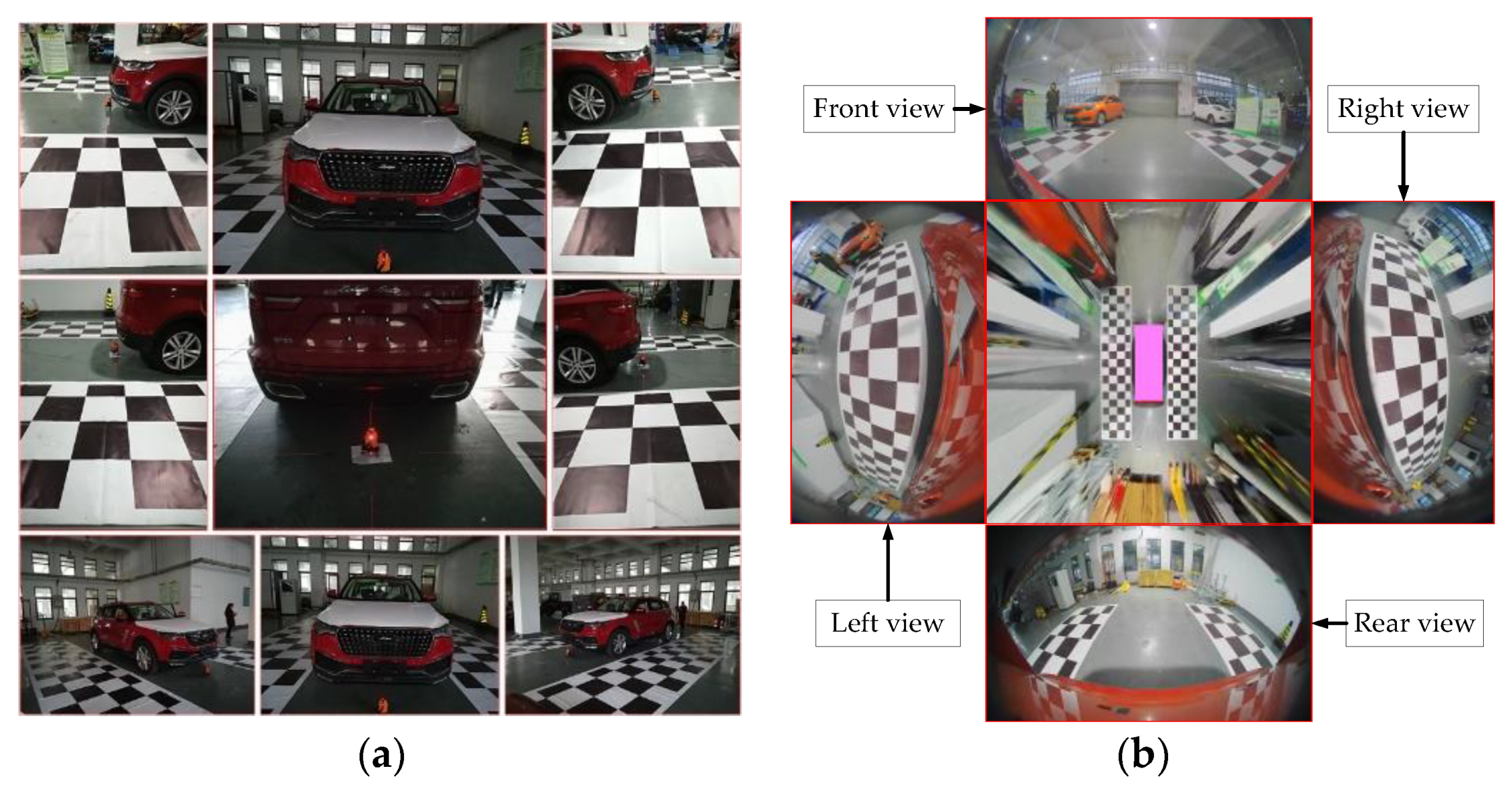
The around-view parking-assist system provides drivers with real-time information on the surrounding environment of the vehicle in an imaging manner. It usually consists of multiple fisheye cameras installed around the vehicle, each camera facing a different direction, thus ensuring that each fisheye camera and the images taken by two adjacent fisheye cameras have overlapping areas.
Four fisheye cameras are mounted on the experimental vehicle, each of which has a horizontal field of view of 180 degrees. We use four fisheye images and camera parameters are input to synthesize a 360-degree panorama around the vehicle image, as shown in Figure 1b.
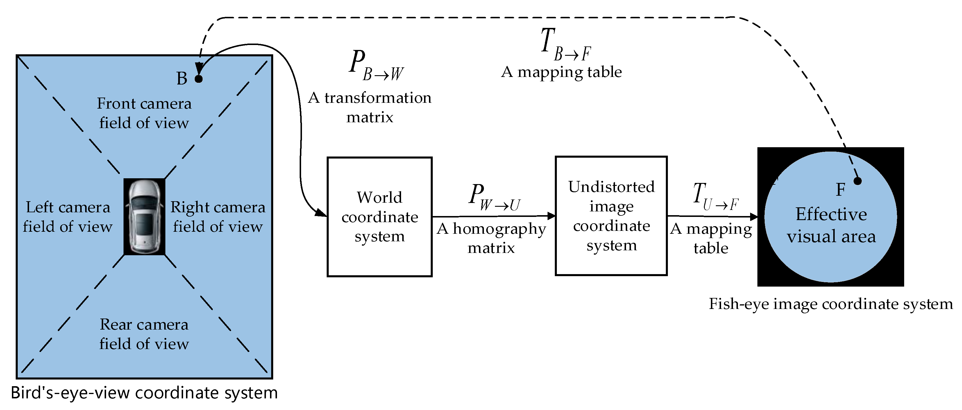
The generation of the AVM image is the process of mapping from the bird’s-eye view coordinate system to the original fisheye image. The key step is to generate the mapping table TB→F, then to take a pixel point F out of the original fisheye image and fill it into a corresponding position B in the bird’s-eye view image based on OpenCL [42] quickly and efficiently. As shown in Figure 2, the mapping process and related coordinate transformation of the bird’s-eye view image are explained.
We divide the bird’s-eye view into four areas and each area corresponds to a mapping table TB→F, as shown in Figure 2. In the traversal of bird’s-eye view image, the coordinates of each pixel are mapped to the world coordinate system by a transformation matrix PB→W, then the world coordinate system is projected to the undistorted image coordinate system by a homography matrix PW→U. Finally, the lookup table TU→F maps a point on the undistorted image to a position on the original input fisheye image.
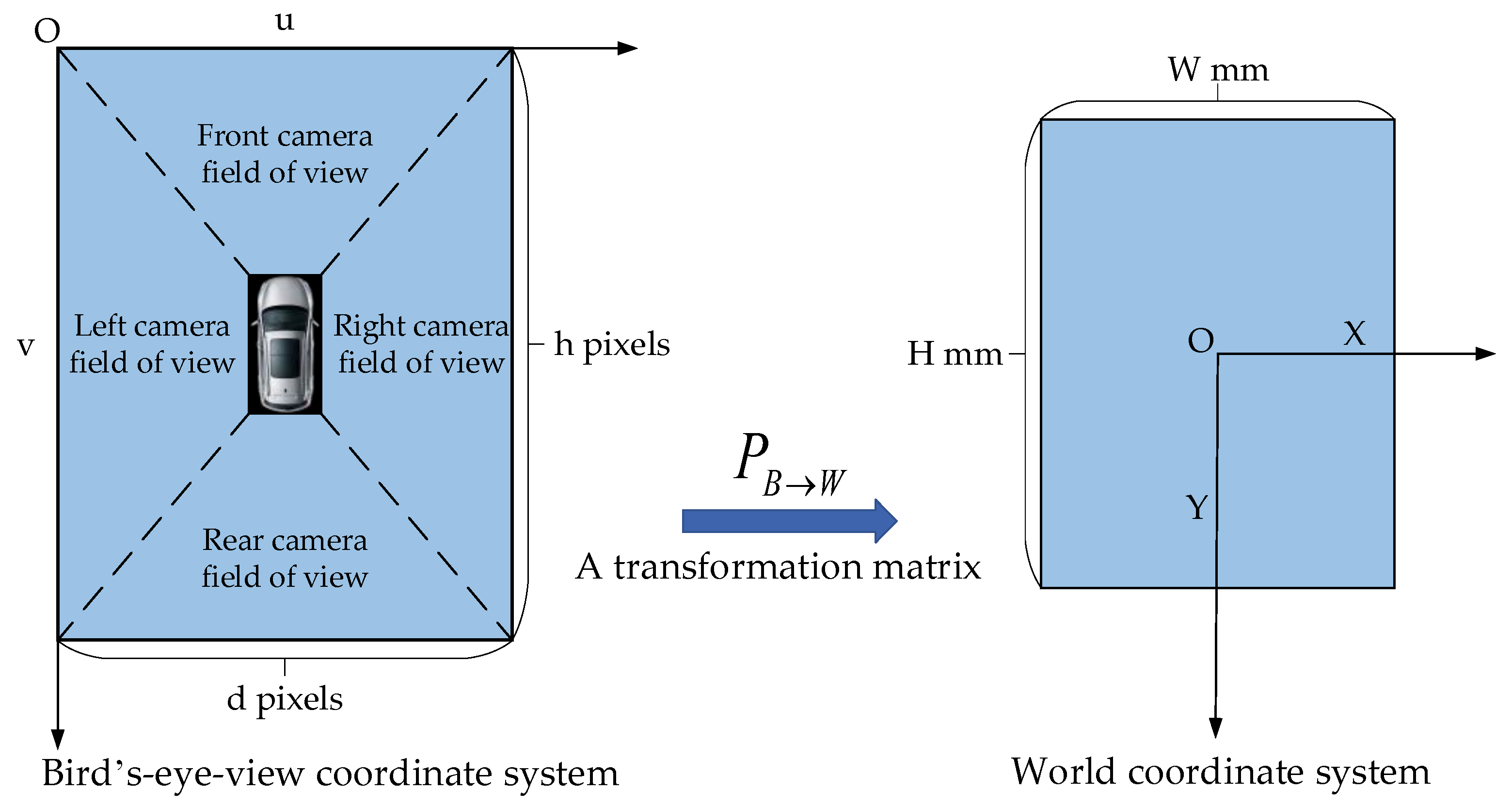
The following describes how to obtain the mapping table TB→F: we create a bird’s-eye view image with a width of pixels and a height of pixels, which is used to display the ground range with the width of mm and the length of mm in the world coordinate system, as shown in Figure 3. Therefore, we get the transformation matrix PB→W:
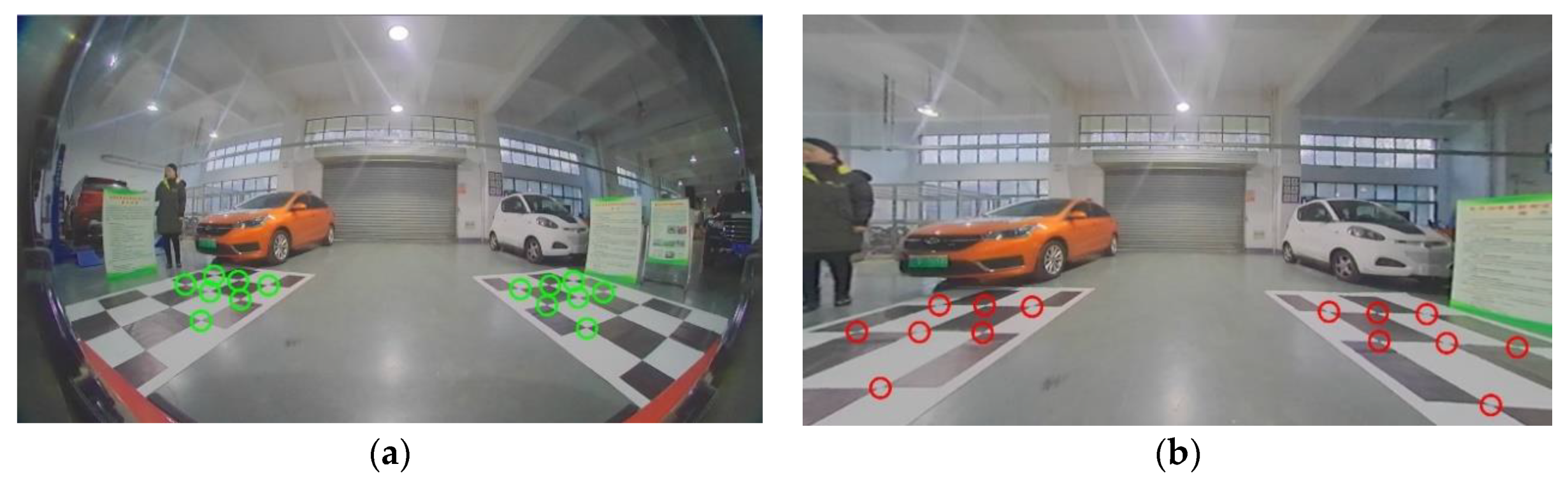
The mapping table TU→F can be determined based on obtaining the distortion coefficients and the parameters of the fisheye camera by Zhang’s calibration method. Accordingly, we correct the original fisheye images to undistorted images based on TU→F. To obtain the homography matrix PW→U, we arrange a checkerboard around the experimental vehicle to obtain the feature points in the world coordinate system. Next, we manually select the corresponding feature points in the undistorted image. The number of feature points i cannot be less than four, as shown in Figure 4. It is known that = PW→U, therefore, PW→U can be estimated based on the least-squares method.
4. Method for Detecting Parking Slots Based on Mask R-CNN
Mask R-CNN is a multi-task deep neural network that combines the ideas of FPN and fully convolutional networks (FCN) [31] base on Faster R-CNN. It does not only effectively detect the marking-points, but also generates high-quality segmentation mask for the marking-points.
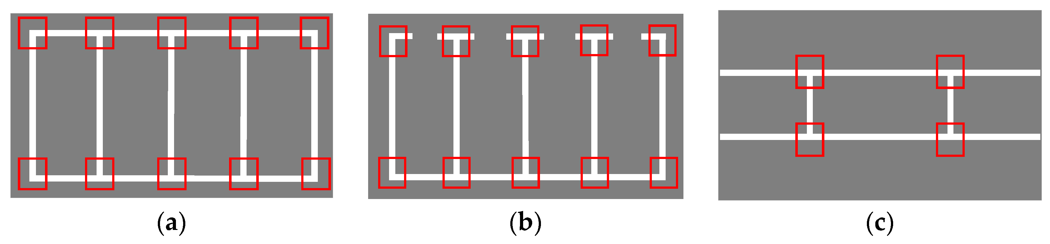
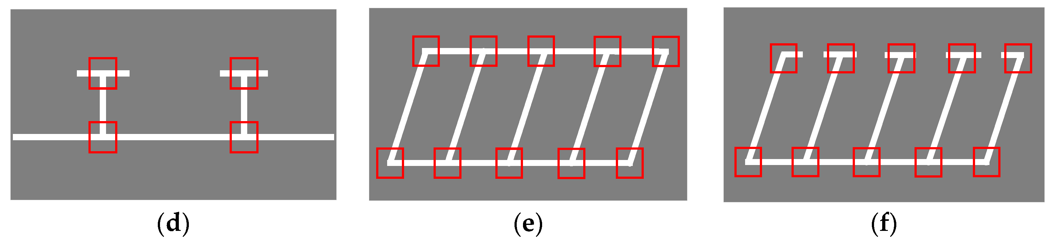
Marking-points are defined as the cross-points of parking lines, showing a T or L shape, as shown in the red rectangles in Figure 5. The main steps of the proposed scheme are as follows: the first part is image preprocessing, including selecting the region of interest (ROI) and contrast enhancement. Next, the mask of marking-points is generated by Mask R-CNN and then, using the LSD algorithm, the guidelines and parallel lines are found, based on the mask. Finally, candidate parking slots can be determined. Figure 6 illustrates an overall flow chart of the proposed scheme.
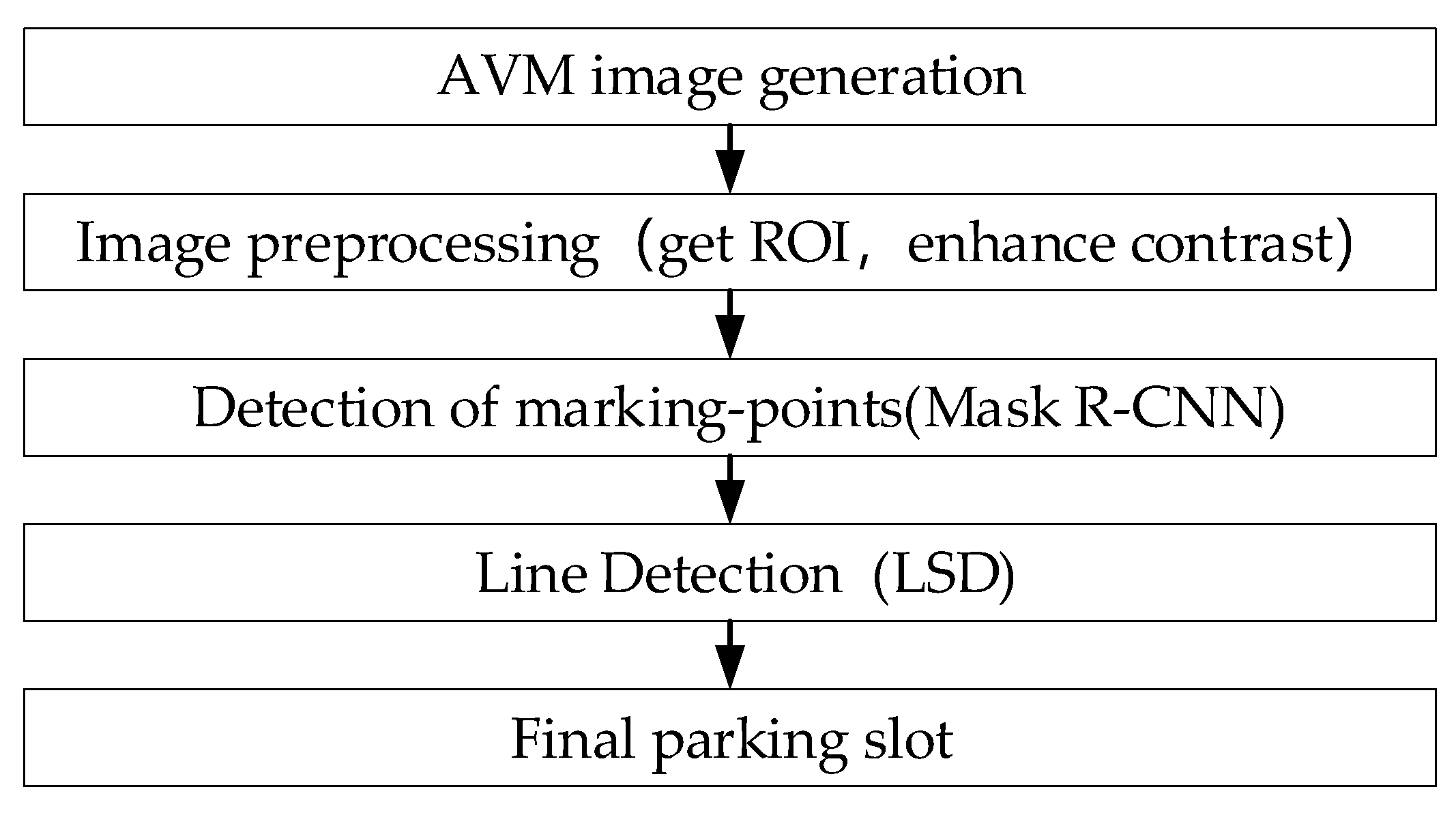
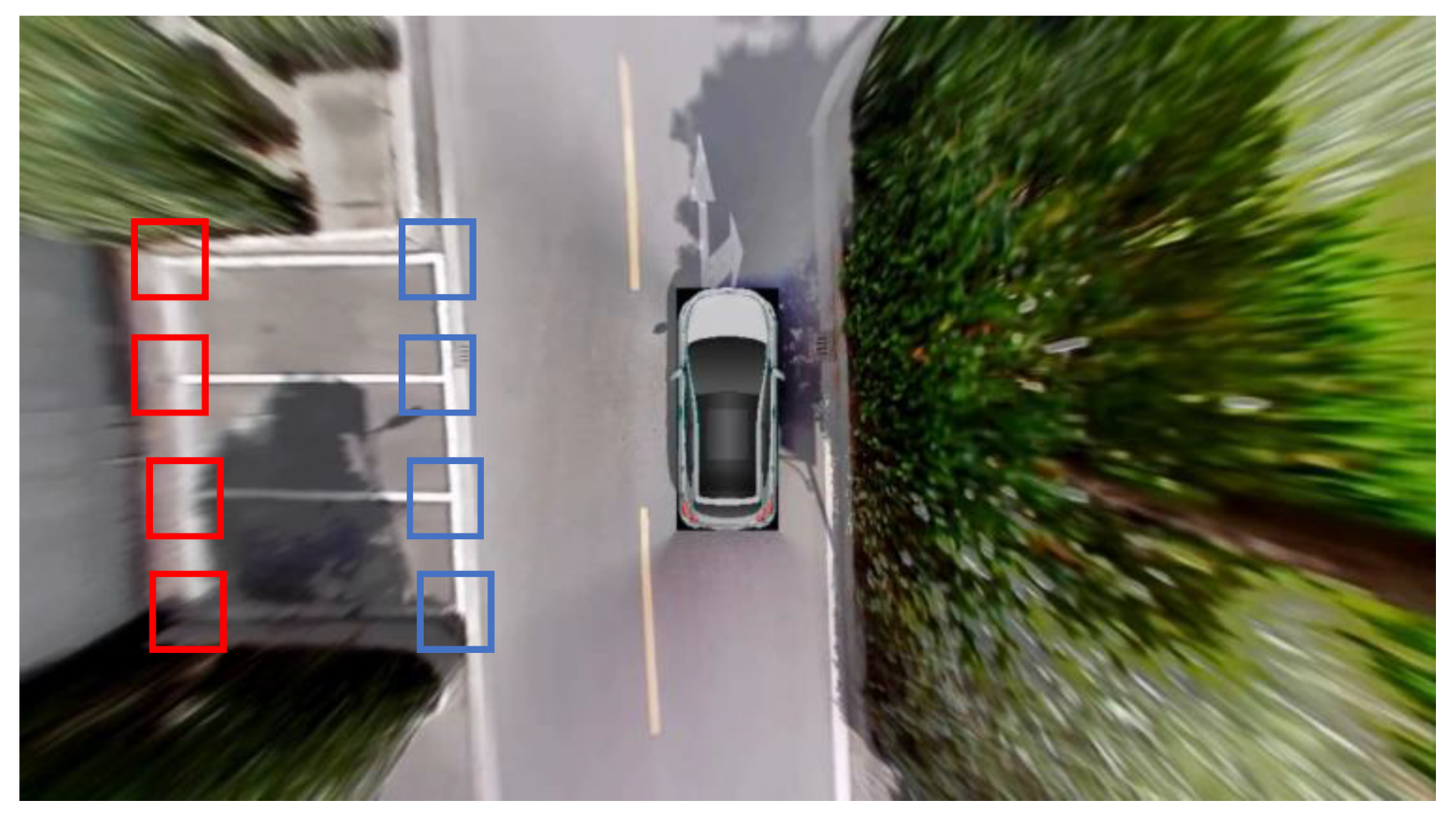
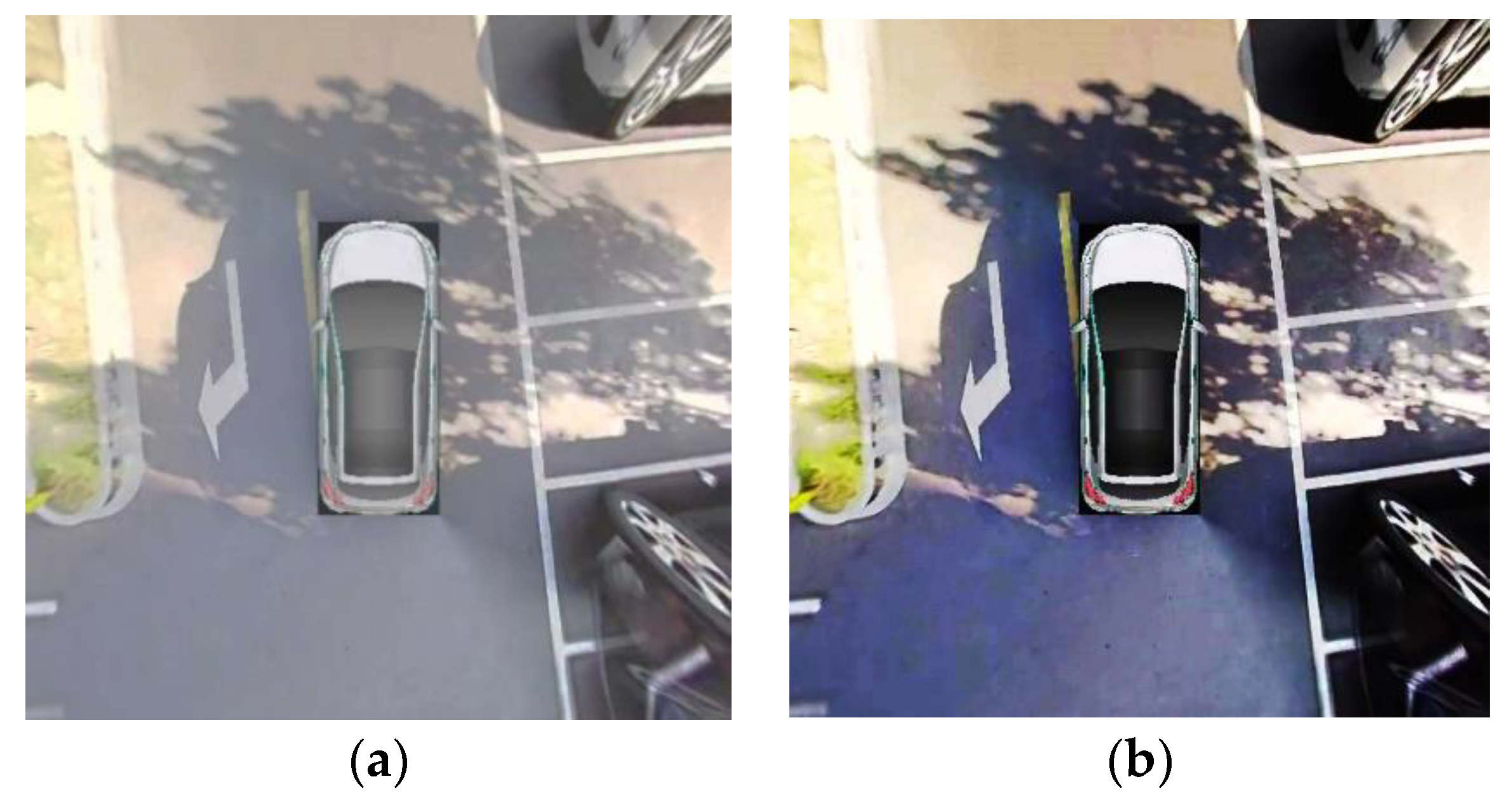
When the driver is driving towards the parking slots, marking-points will appear on both sides of the vehicle, as shown in the blue rectangles in Figure 7. We define the ROI instead of detecting marking-points on the entire image, which reduces computing resources. Besides, the further away from the AVM image center, the more severe the distortion. For the vertical parking slots in particular, some marking-points are blurred, as shown in the red rectangles in Figure 7. Blurred marking-points increase the difficulty of sample annotation. Therefore, it is difficult to detect all the markings based on the entire image.
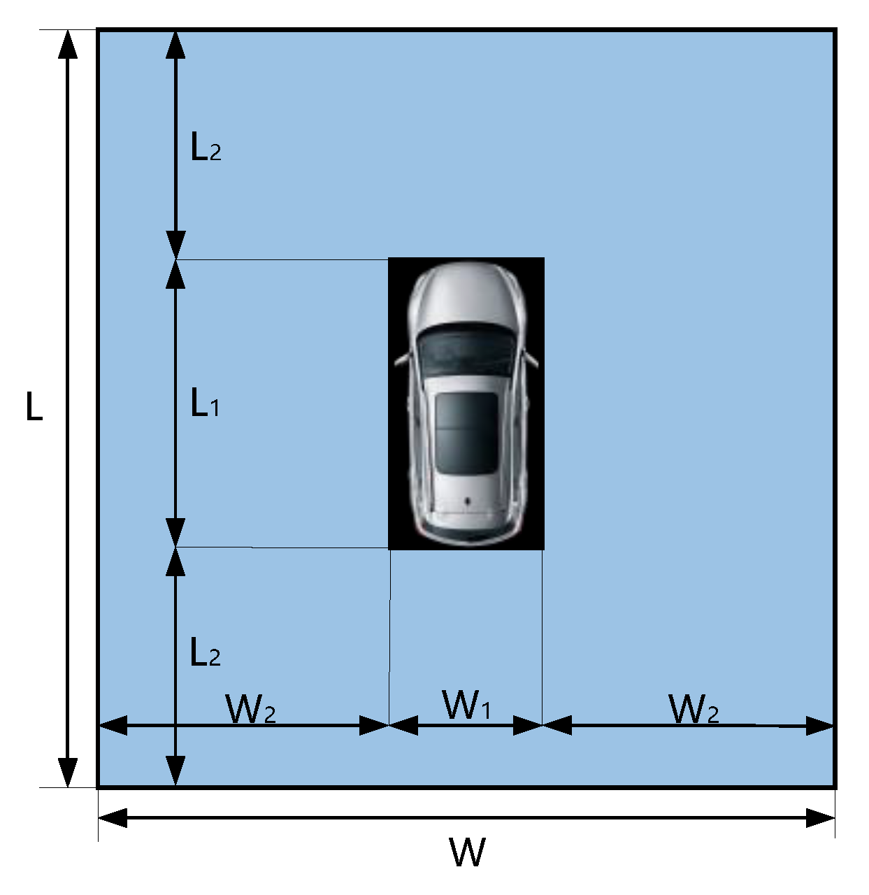
The specific ROI parameters are shown in Figure 8, where L and W represent the length and width of the ROI region, L1 and W1 represent the length and width of the vehicle. The geometric constraints are L = L1 + 2 * L2, W = W1 + 2 * W2.
4.1. Production of the Training Set
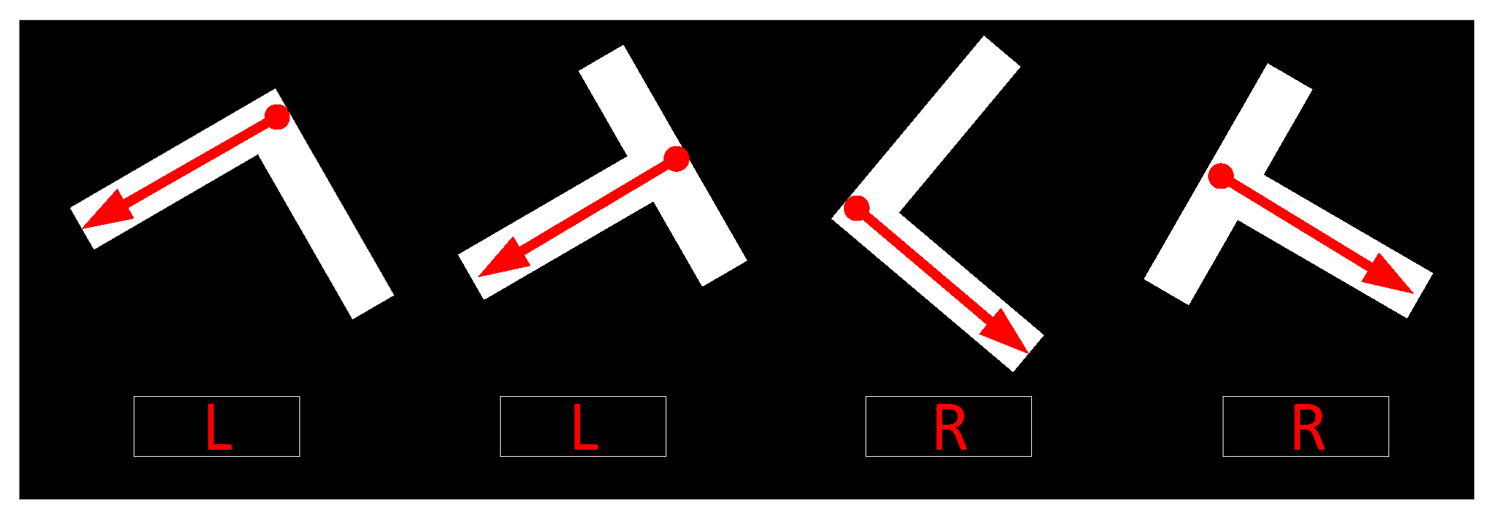
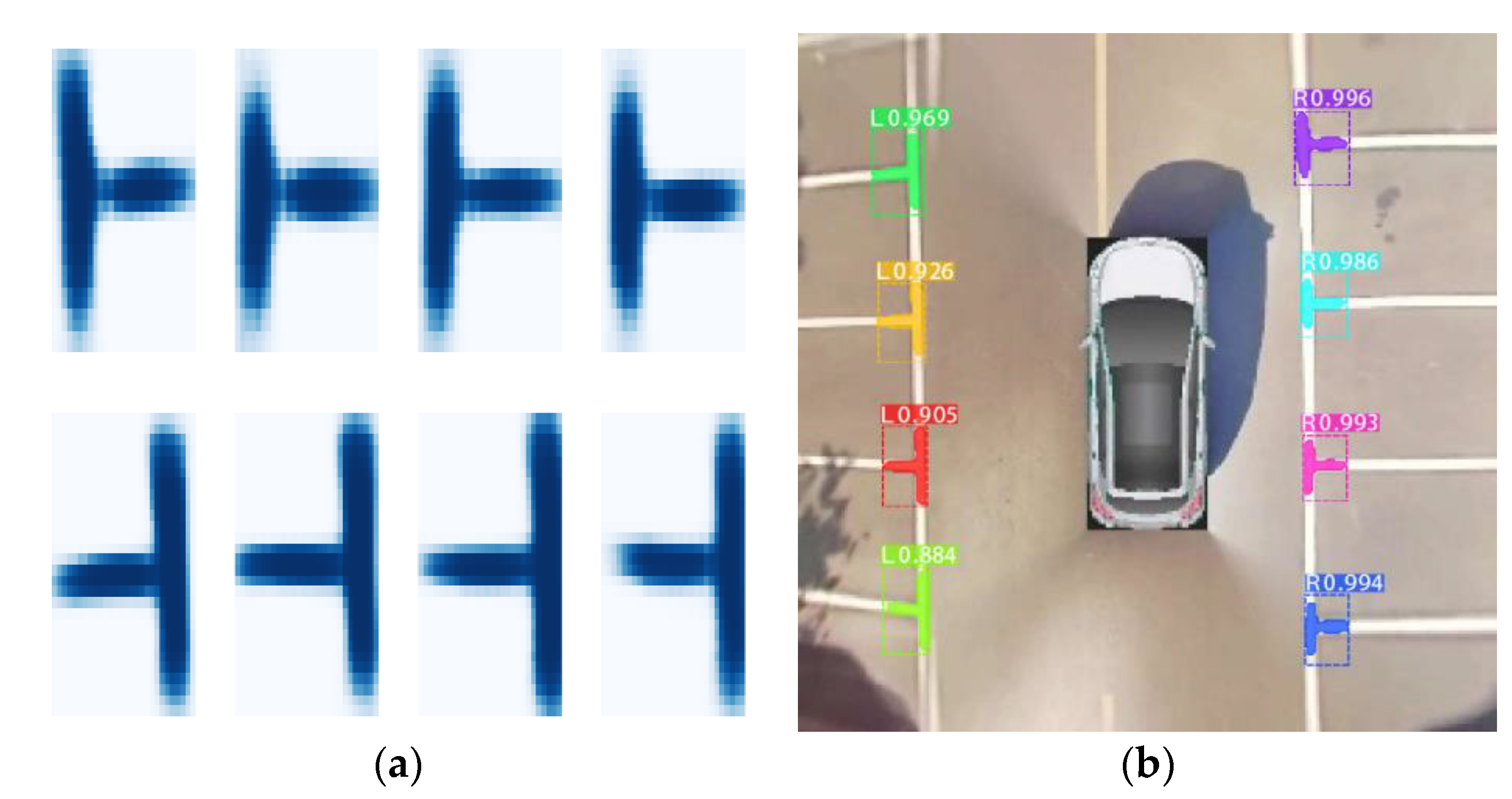
Since the orientation of the marking-point is arbitrary, to gain a better training effect, we rotate each positive image patch with a set of angles [2πrk, where rk is a random number uniformly distributed over (−1,1), and K defines the number of possible sample rotations. That is, if N positive samples are labeled, we will obtain NK positive samples for training. Next is to enhance the contrast of the samples with Laplace operator, which effectively highlights the edge information of marking-points under the condition of light blocked as shown in Figure 9. The orientation of marking-point is divided into two categories, R belongs (−π/2, π/2), L belongs (π/2, −π/2), as shown in Figure 10. This step is helpful to determine the orientation of the parking-slot after using the LSD algorithm to detect parallel lines. Please refer to Section 4.3 for details.
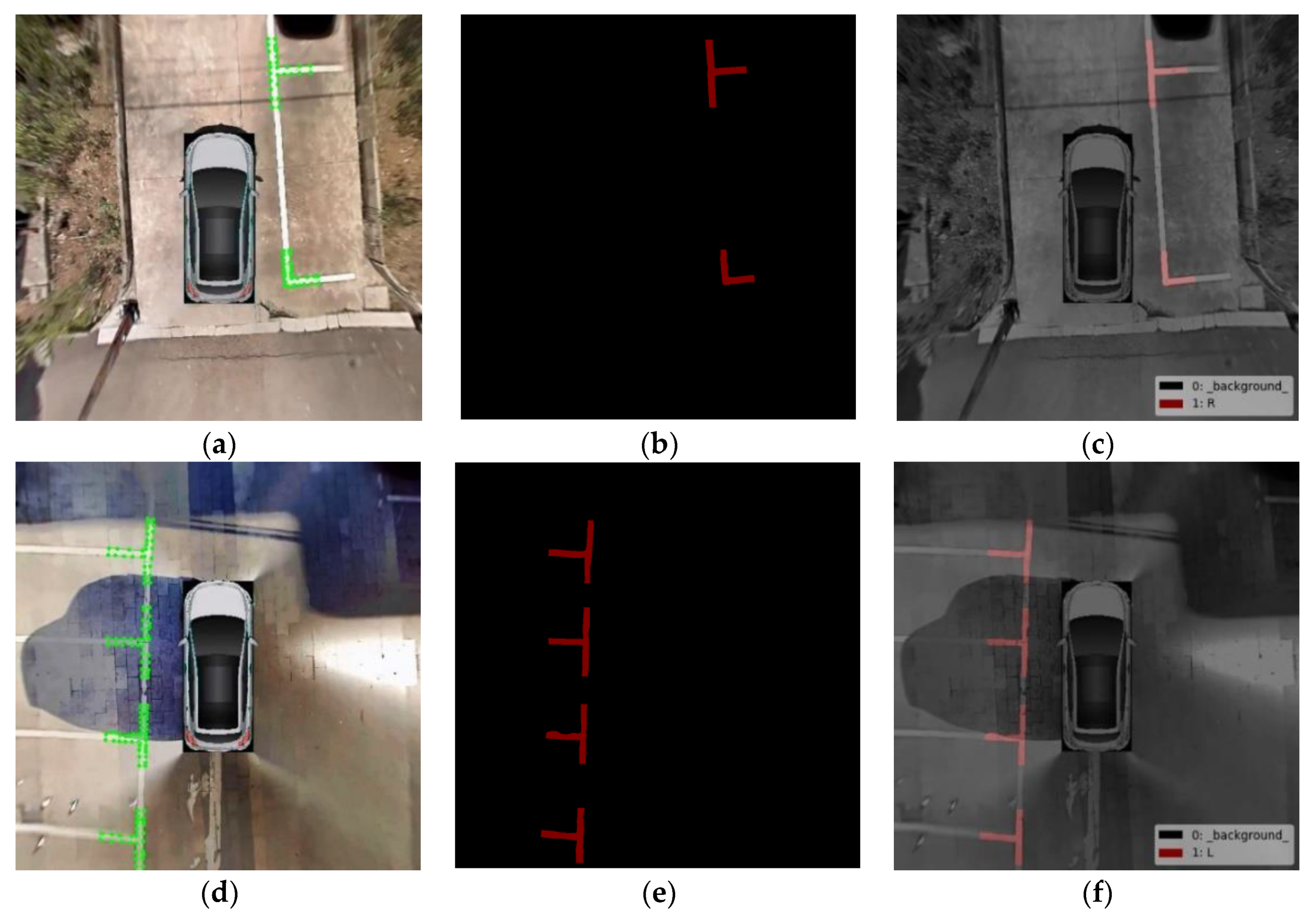
Labelme [43] is a web-based open graphical image annotation tool which supports image annotation for polygon, rectangle, circle, line and point and also image flag annotation for classification and cleaning. Labelme is used to annotate the marking-points in the AVM image. We use the mouse to click the outline of the marking-points and determine its classification, then save it as a JSON file, as shown in Figure 11. The generated JSON files storing annotation information are converted into the training images for Mask R-CNN, as shown in Figure 12.
4.2. Build Mask R-CNN Training Model
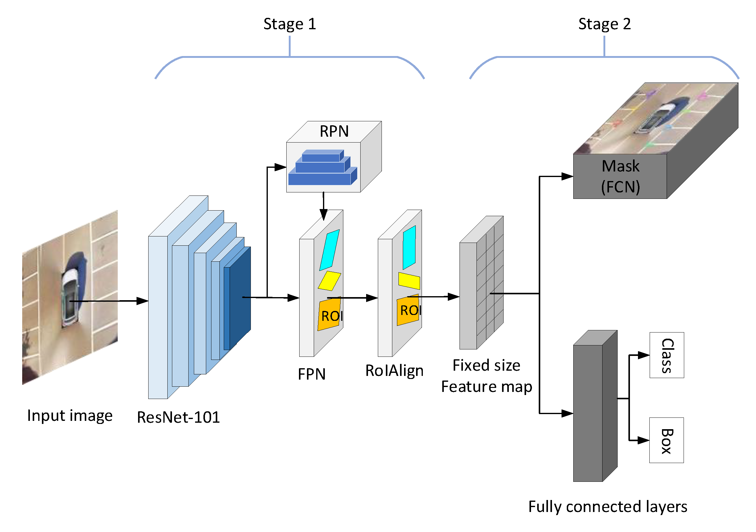
Mask R-CNN is a two-stage framework. In the first stage, the backbone network of Mask R-CNN (Resnet101 and FPN) extracts and combines the feature maps of the AVM image. The regional proposal network (RPN) is used to recommend anchors of marking-points, then anchors with high scores can be found by filtering and correcting. In the second stage, the category and position of each anchor are predicted, and the corresponding mask of marking-points is generated. The overall network structure is shown in Figure 13.
The above two stages are described in detail as follows: the powerful Resnet101 was selected to extract the feature of marking-point. We took 4 different scales of feature maps (C1,C2,C3,C4) output by Residual Block. These feature maps were used to establish the feature pyramid of FPN network, and get new features (P2,P3,P4,P5,P6), respectively. The feature combination process is shown in Equation (2). For i = 5, 4, 3, 2, U6 = 0:
where sum represents the element-by-element alignment operation, conv represents the convolution operation, upsample represents the upsampling operation that doubles the length and width of the feature map and pooling represents maximum pooling operation with a stride of 2.
Anchors of marking-points are recommended by the region proposal network (RPN). A sliding window is used to slide on the five feature maps (P2,P3,P4,P5,P6). After the sliding operation, the 2k dimension classification and 4k dimension position information are regressed to describe the correction values of k anchors. The correction values of each anchor include Δx, Δy, Δh, ΔW, P, where P is the confidence degree of foreground and background. Formula (3) is the correct formula for anchors:
where (x,y) is the coordinate of anchor center point, w and h are the width and height of anchor, respectively, and x′, y′, w′, h′ are corresponding correction values. The correction process is shown in Figure 14a. After the correction of a large number of anchors is completed, the non-maximum suppression method (NMS) [31] is used to retain anchors with high foreground scores and transfer them to the next stage, as shown in Figure 14b.
To map the ROI in different sizes of anchors to the feature map of fixed size, ROI Align is proposed to select four regular positions in each ROI block, while double-line interpolation is used to calculate the exact value of each position and summarize the results. Finally, uniform ROIs are classified, the position of anchors is regressed and the mask of marking-point is generated by FCN. As shown in Figure 15a,b, Figure 16 shows the AVM image with marking-points detected by Mask R-CNN.
4.3. Parking-Slot Inference Base on Marking-Points
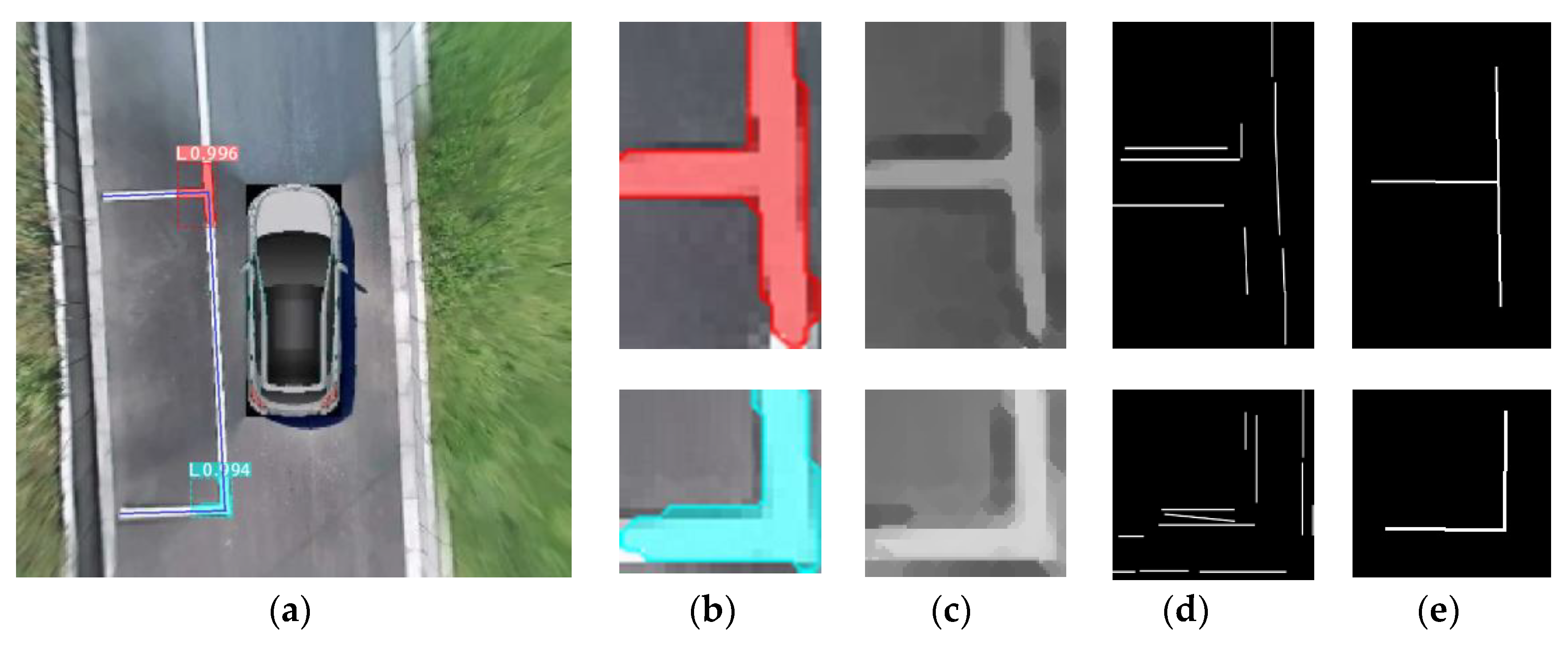
Having detected the marking-points (parking slots normally correspond to two marking-points), as shown in Figure 17b, we can perform the following steps to infer parking slots. We carry on corrosion and dilation operations to the mask of marking-points first, as shown in Figure 17c. Then, the mask is used to detect lines base on the LSD algorithm, as shown in Figure 17d. The line segments where the length does not meet a certain threshold value need to be removed. For similar lines, we take the average of the slope and intercept, merge them into a line as shown in Figure 17e and get the guidelines and parallel lines. Each parallel line points to two opposite directions. According to the classified results: left(L) and right(R) of the marking-point, the orientation of the parking slot can be identified. Finally, the “depth” of the parking slots is determined by prior knowledge.
5. Experimental Result
5.1. Training Platform and Selection of Pre-Training Model
The proposed method is written in Python 3.7, training and testing are completed under baiGraphic Processing Unit (GPU) acceleration. Tensorflow is used as the basis for construction, the computer is configured as a GTX1070TI with an 8 GB memory graphics card, considering that the training of the Mask R-CNN model requires a lot of time and dozens of training samples for higher level of accuracy. To improve the detection accuracy of the model, we use the transfer learning method to take the weight model obtained from the official coco2014 dataset [44] as the pre-training model of the marking-point detection algorithm.
5.2. Evaluating the Performance of Marking-Point Detection
We collected a total of 4500 AVM images. As to the distribution of training, validation and test, we refer to other common datasets [45,46] by the ratio of 6:1:3. In detail, the numbers of images for training, validation and test are 2700, 450 and 1350, respectively.
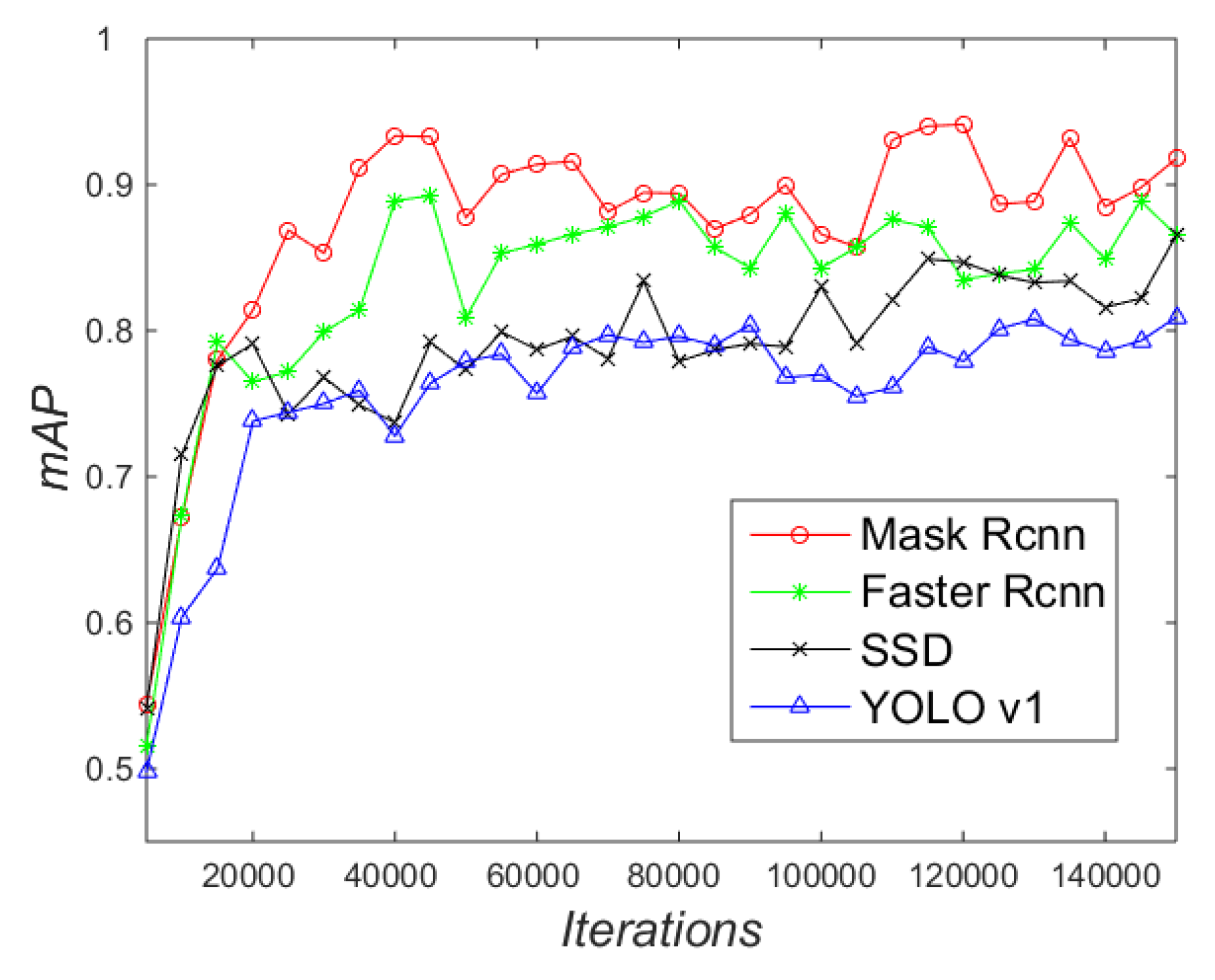
The mAP is the mean average precision [31], as shown in Figure 18. When the iterations are less than 20,000, the mAP of the four methods is 0.82 lower; as the iterations increase, the overall mAP of Mask R-CNN and Faster R-CNN is higher than that of SSD [47] and Yolo v1 [48]. The main reason is that there are differences in the mechanism of generating initial anchors between the above methods. Mask R-CNN and Faster R-CNN use the RPN network to generate scores of anchors on feature image, while Yolo v1 and SSD divide a certain number of grids on the original image to directly regress, which has obvious advantages and disadvantages. The detection effect of small-sized marking-points is poor, but the detection speed of SSD and YOLO v1 is up to 18 fps and 22 fps, respectively, as shown in Table 1.
The mAP of SSD is maintained at about 0.82; compared with YOLO v1, SSD divides multiple scales of the grids on the original map for regression, which performs better in detecting the small size of marking-points. Hence, the mAP of SSD is slightly better than that of Yolo v1. Mask R-CNN uses Resnet101 instead of Vgg16 in Faster R-CNN to extract the feature of marking-points, which improves the ability to extract and recognize the image features. Therefore, the mAP of Mask R-CNN is always higher than that of Faster R-CNN during the entire training. However, due to the addition of the FCN branch, which is used to generate the mask of marking-points, the detection speed of Mask R-CNN (2 fps) is lower than that of Faster R-CNN (7 fps), as shown in Table 1.
5.3. Evaluating the Performance of Parking-Slot Detection
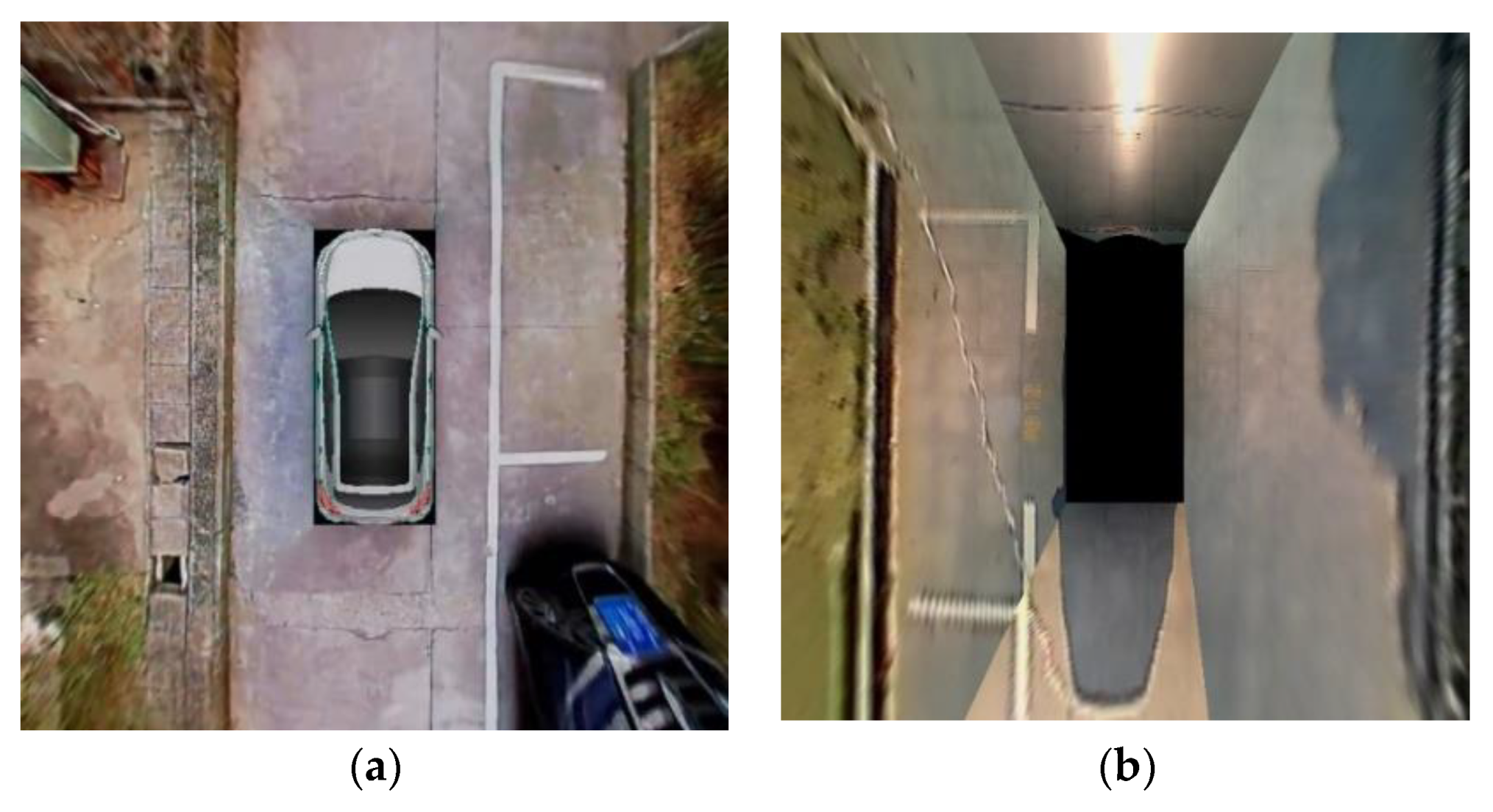
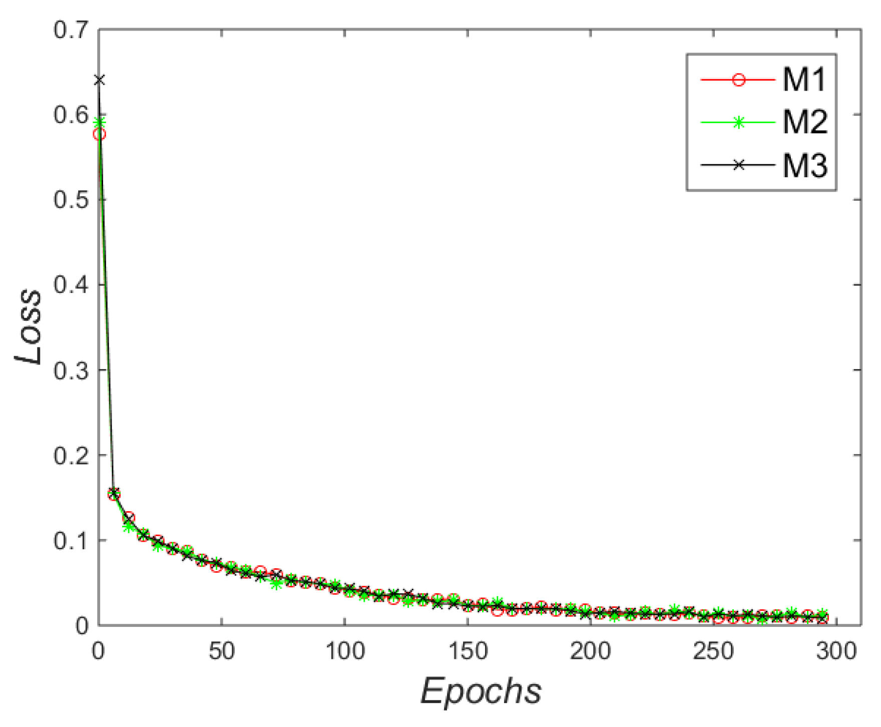
To facilitate the study of vision-based parking-slot detection, Zhang et al. [16] established the public dataset [49] of AVM images and made it publicly available to the research community. Previous approaches used a single type of AVM images for training and testing, but the quality of the fisheye image stitching algorithm affects the detection of marking-points. As shown in Figure 19, the clarity and stitching effect of Figure 19a are significantly better than that of Figure 19b. To test the generalizability of the proposed approach, we divided the training samples into three groups, of which groups 1 and 2 each had 4000 AVM images that were from our experimental vehicle and the public dataset [49], respectively; 2000 AVM images were randomly selected from group 1 and group 2, respectively, which were used to form group 3. The initial learning rate was set to 0.0001 and the training epoch was 300, the corresponding Mask R-CNN model—M1, M2, M3—were obtained by training, respectively.
This paper trains the Mask R-CNN model by reducing the loss function between the predicted value and the real label. The loss function of Mask R-CNN is defined as follows:
where Lcls indicates the classification error, Lbox is the bounding box regression error, Lmask indicates the mask error. Figure 20 shows the loss during the entire training. It can be seen that three models converge to 0.05 when they are trained to the 300th epoch, indicating that the proposed method for detecting marking-points based on Mask R-CNN has certain robustness.
Table 2 shows the slot-detection performances among different methods. The test dataset consists of 256 AVM images from the experimental vehicle and the public dataset [49], which includes various types of parking slots under complex illumination. Precision, recall, accuracy and F1 scores in Formulas (5)–(8) are utilized as performance measures.
It can be seen that compared with traditional corner detector and line detection, the three Mask R-CNN models have better performance, of which the accuracy, precision, recall and F1 scores of M3 are 93.4%, 94.5%, 92.7% and 93.5%, respectively. The main reason is that Mask R-CNN has a strong ability to extract image features of marking-points, especially in underground parking slots or at night, where the light is dim or in the presence of reflected light. The accuracy of the method in Zhang et al. [16] was lower than that of M3—only 88.8%—because if slot marking’s contrast with the ground is not remarkable, parking slots are classified as free space. In addition, the method can detect only two parking types: perpendicular and parallel parking. Faster R-CNN cannot detect the four vertices of parking slots when the complete parking slots are often unable to be presented in the AVM images, and the lane lines are often mistakenly regarded as the parking lines; therefore, its accuracy is only 82.2%. Corner features cannot always provide precise target positions and heading angles, besides, it is difficult for a corner feature to maintain robustness. Meanwhile, the line-based method provides an accurate direction and has fewer constraints compared with corner-based methods. Therefore, the accuracy and F1 scores of the line-based method are 7.3% and 4.3% higher than that of the corner-based method.
In all training images of M2 there are obvious splice marks that affect the feature extraction of marking-points, as shown in Figure 19b. It is prone to generating false detection against the background of light and shade interlacing, which means that the number of false positives in M2 was higher than that in M1 and M3 during the test. Therefore, the recall of M2 is slightly lower than that of M1 and M3. Since M1 and M2 use only a single source of AVM images for training, the precision of M1 and M2 are 5.2% and 3.3% lower than that of M3, respectively, indicating that increasing the diversity of training samples can improve the generalization ability of Mask R-CNN. It also reflects that the proposed method can realize the detection of parking slots in different around-view parking-assist systems.
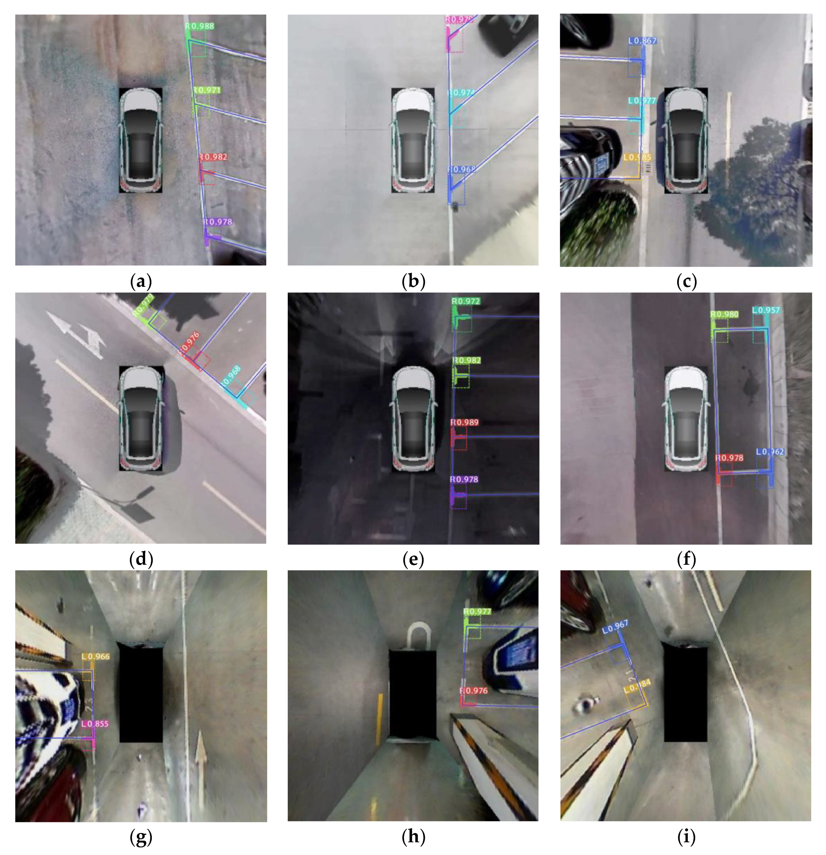
AVM images with parking slots detected by Mask R-CNN are shown in Figure 21. Figure 21a,b shows slanted parking slots with different tilt angles, Figure 21c,d shows vertical parking slots; it can be found that the mask of marking-points accurately separates the guideline from the adjacent lane line. Figure 21e,f shows outdoor parking slots at night, Figure 21g–i shows indoor parking slots. From the above test samples, we conclude that the proposed method has a strong capability for accurately detecting different types of parking slots under various conditions.
6. Conclusions and Future Research
To detect parking slots, many previous studies conducted primitive feature extractions of the parking-slot markings, for instance, the corner detector and line method. Although these methods detect slot markings moderately well in bright light, they are rather ineffective regarding shadows or faint lines and corners. The method in Zhang et al. [16] increases the precision and recall to 86.9% and 87.3%, but it cannot detect slanted parking slots and needs to train multiple marking-point detectors. Compared with Faster R-CNN, the proposed method adds the FCN branch to generate the mask of marking-points, which determines the direction of the parking slots and separates the guideline from the adjacent lane line accurately. Moreover, the proposed method was evaluated in various parking conditions and has higher precision (94.5%) and recall (92.7%).
We employed deep-learning-based Mask R-CNN on an AVM image, a large number of AVM images were made and collected. The experimental results showed that the trained model had strong adaptability and could accurately find the marking points in the AVM images with different stitching effects and separate the guideline from the adjacent lane line. This suggests that expanding the training set could allow the trained model to recognize the vast majority of parking-slot types. The main advantage of this method over the current state of the art for parking-slot detection is its generalizability and accuracy of detecting different kinds of slots, like parallel, perpendicular and slanted, under different lighting and observation conditions.
The detection speed of the proposed method only reached 2 fps, which cannot meet the real-time requirements of parking slots detection, the precision and recall need to be further improved. Future research can look at expanding the scale of labeled datasets to enrich the diversity of samples and optimizing the structure of Mask R-CNN to improve the performance. Additionally, the studies can be expanded to judge whether the parking slots are occupied by combining with obstacle detection.
Author Contributions
S.J. and S.M. installed and calibrated fisheye cameras. H.J. designed the image stitch algorithm. S.J. and H.J. collected and made training samples. S.J. built the training model. S.J. wrote the paper with the help of H.J. and Z.J. All authors have read and agreed to the published version of the manuscript.
Funding
Jiangsu Province Industry University Research Institute joint innovation fund prospective joint research project (No.BY2012173) and Major University Nature Science Research Project of Jiangsu Province (No.16KJA580001) and the Innovation Plan for Postgraduate Research of Jiangsu Province in 2014 under Grant KYLX1057.
Conflicts of Interest
The authors declare no conflicts of interest.
References
- Hua, Y.; Ma, S.; Ma, J.; Jiang, H.; Zhang, D. Integrated model of assisted parking system and performance evaluation with entropy weight extended analytic hierarchy process and two-tuple linguistic information. Adv. Mech. Eng. 2016, 8, 1–14. [Google Scholar] [CrossRef] [Green Version]
- Ye, H.; Jiang, H.; Ma, S.; Tang, B.; Wahab, L. Linear model predictive control of automatic parking path tracking with soft constraints. Int. J. Adv. Robot. Syst. 2019, 16. [Google Scholar] [CrossRef] [Green Version]
- Al-Turjman, F.; Malekloo, A. Smart parking in IoT-enabled cities: A survey. Sustain. Cities Soc. 2019, 49, 101608. [Google Scholar] [CrossRef]
- Heimberger, M.; Horgan, J.; Yogamani, S.; Hughes, C.; McDonald, J. Computer vision in automated parking systems: Design, implementation and challenges. Image Vis. Comput. 2017, 68, 88–101. [Google Scholar] [CrossRef]
- De Almeida, P.R.; De Oliveira, L.E.S.; Britto, A.S.; Silva, E.J.; Koerich, A.L. PKLot—A robust dataset for parking lot classification. Expert Syst. Appl. 2015, 42, 4937–4949. [Google Scholar] [CrossRef] [Green Version]
- Schmid, M.R.; Ates, S.; Dickmann, J. Parking Space Detection with Hierarchical Dynamic Occupancy Grids. In Proceedings of the 2011 IEEE Intelligent Vehicles Symposium, Baden-Baden, Germany, 5–9 June 2011; pp. 254–259. [Google Scholar]
- Dube, R.; Hahn, M.; Schuetz, M. Detection of Parked Vehicles from a Radar Based Occupancy Grid. In Proceedings of the 2014 IEEE Intelligent Vehicles Symposium Proceedings, Dearborn, MI, USA, 8–11 June 2014; pp. 1415–1420. [Google Scholar]
- Jung, H.G.; Cho, Y.H.; Yoon, P.J.; Kim, J. Scanning Laser Radar-Based Target Position Designation for Parking Aid System. IEEE Trans. Intell. Transp. Syst. 2008, 9, 406–424. [Google Scholar] [CrossRef]
- Zhou, J.; Navarro-Serment, L.E.; Hebert, M. Detection of Parking Spots Using 2D Range Data. In Proceedings of the 2012 15th International IEEE Conference on Intelligent Transportation Systems, Anchorage, AK, USA, 16–19 September 2012; pp. 1280–1287. [Google Scholar]
- Ibisch, A.; Stuemper, S.; Altinger, H. Towards Autonomous Driving in a Parking Garage: Vehicle Localization and Tracking Using environment-embedded LIDAR Sensors. In Proceedings of the 2013 Ieee Intelligent Vehicles Symposium, Gold Coast, Australia, 23–26 June 2013; pp. 829–834. [Google Scholar]
- Tong, L.; Cheng, L.; Li, M.; Wang, J.; Du, P. Integration of LiDAR Data and Orthophoto for Automatic Extraction of Parking Lot Structure. IEEE J. Sel. Top. Appl. Earth Obs. Remote Sens. 2013, 7, 503–514. [Google Scholar] [CrossRef]
- Jiang, H.B.; Ye, H.; Ma, S.D. Method for accurately identifying parking space of automatic parking system based on multi-sensor data fusion. J. Chongqing Univ. Technol. 2019, 33, 1–10. [Google Scholar]
- Jeong, S.H.; Choi, C.G.; Oh, J.N.; Yoon, P.J.; Kim, B.S.; Kim, M.; Lee, K.H. Low cost design of parallel parking assist system based on an ultrasonic sensor. Int. J. Automot. Technol. 2010, 11, 409–416. [Google Scholar] [CrossRef]
- Ford Fusion. Available online: http://www.ford.com/cars/fusion/features/#page=-Feature15 (accessed on 23 February 2019).
- BMW 7 Series Sedan. Available online: http://www.bmw.com/com/en/newvehicles/7series/sedan/2012/showroom/driver_assistance/park-assistant.html (accessed on 23 February 2019).
- Zhang, Z.Y. A flexible new technique for camera calibration. IEEE Trans. Pattern Anal. Mach. Intell. 2000, 22, 1330–1334. [Google Scholar] [CrossRef] [Green Version]
- Bay, H.; Ess, A.; Tuytelaars, T.; Van Gool, L. Speeded-Up Robust Features (SURF). Comput. Vis. Image Underst. 2008, 110, 346–359. [Google Scholar] [CrossRef]
- Schou, J.; Scherrer, P.H.; Bush, R.I.; Wächter, R.; Couvidat, S.; Rabello-Soares, M.C.; Bogart, R.S.; Hoeksema, J.T.; Liu, Y.; Duvall, T.L.; et al. Design and Ground Calibration of the Helioseismic and Magnetic Imager (HMI) Instrument on the Solar Dynamics Observatory (SDO). Sol. Phys. 2011, 275, 229–259. [Google Scholar] [CrossRef] [Green Version]
- Brook, A.; Ben Dor, E. Automatic Registration of Airborne and Spaceborne Images by Topology Map Matching with SURF Processor Algorithm. Remote. Sens. 2011, 3, 65–82. [Google Scholar] [CrossRef] [Green Version]
- Sedaghat, A.; Ebadi, H. Remote Sensing Image Matching Based on Adaptive Binning SIFT Descriptor. IEEE Trans. Geosci. Remote Sens. 2015, 53, 5283–5293. [Google Scholar] [CrossRef]
- Zhang, J.; Chen, G.; Jia, Z. An Image Stitching Algorithm Based on Histogram Matching and SIFT Algorithm. Int. J. Pattern Recognit. Artif. Intell. 2017, 31, 1754006. [Google Scholar] [CrossRef] [Green Version]
- Chen, J.-Y.; Hsu, C.-M. A visual method for the detection of Available Parking Slots. In Proceedings of the 2017 IEEE International Conference on Systems, Man, and Cybernetics, Banff, AB, Canada, 5–8 October 2017; pp. 2980–2985. [Google Scholar]
- Suhr, J.K.; Jung, H.G. Fully-automatic Recognition of Various Parking Slot Markings in Around View Monitor (AVM) Image Sequences. In Proceedings of the 2012 15th International IEEE Conference on Intelligent Transportation Systems, Anchorage, AK, USA, 16–19 September 2012; pp. 1294–1299. [Google Scholar]
- Suhr, J.K.; Jung, H.G. Full-automatic recognition of various parking slot markings using a hierarchical tree structure. Opt. Eng. 2013, 52, 37203. [Google Scholar] [CrossRef]
- Suhr, J.K.; Jung, H.G. Sensor Fusion-Based Vacant Parking Slot Detection and Tracking. IEEE Trans. Intell. Transp. Syst. 2013, 15, 21–36. [Google Scholar] [CrossRef]
- Jung, H.G.; Kim, D.S.; Yoon, P.J. Parking slot markings recognition for automatic parking assist system. In Proceedings of the 2006 IEEE Intelligent Vehicles Symposium, Tokyo, Japan, 13–15 June 2006; pp. 106–113. [Google Scholar]
- Wang, B.; Zhang, H.; Yang, M.; Wang, X.; Ye, L.; Guo, C. Automatic Parking Based on a Bird’s Eye View Vision System. Adv. Mech. Eng. 2014, 6, 847406. [Google Scholar] [CrossRef]
- Suhr, J.K.; Jung, H.G. A Universal Vacant Parking Slot Recognition System Using Sensors Mounted on Off-the-Shelf Vehicles. Sensors 2018, 18, 1213. [Google Scholar] [CrossRef] [Green Version]
- Houben, S.; Komar, M.; Hohm, A. On-Vehicle Video-Based Parking Lot Recognition with Fisheye Optics. In Proceedings of the 2013 16th International IEEE Conference on Intelligent Transportation Systems, The Hague, The Netherlands, 6–9 October 2013; pp. 7–12. [Google Scholar]
- Lee, S.; Seo, S.-W. Available parking slot recognition based on slot context analysis. IET Intell. Transp. Syst. 2016, 10, 594–604. [Google Scholar] [CrossRef]
- He, K.; Gkioxari, G.; Dollar, P. Mask R-CNN. In Proceedings of the 2017 IEEE International Conference on Computer Vision, Venice, Italy, 22–29 October 2017; pp. 2980–2988. [Google Scholar]
- Von Gioi, R.; Jakubowicz, J.; Morel, J.-M.; Randall, G. LSD: A Fast Line Segment Detector with a False Detection Control. IEEE Trans. Pattern Anal. Mach. Intell. 2008, 32, 722–732. [Google Scholar] [CrossRef] [PubMed]
- He, K.; Zhang, X.; Ren, S. Identity Mappings in Deep Residual Networks. Computer. In European Conference on Computer Vision; Springer: Cham, Switzerland, 2016; Volume 9908, pp. 630–645. [Google Scholar]
- Cole, M.W.; Reynolds, J.R.; Power, J.D.; Repovš, G.; Anticevic, A.; Braver, T.S. Multi-task connectivity reveals flexible hubs for adaptive task control. Nat. Neurosci. 2013, 16, 1348–1355. [Google Scholar] [CrossRef] [PubMed]
- Zhang, L.; Li, X.; Huang, J.; Shen, Y.; Wang, D. Vision-Based Parking-Slot Detection: A Benchmark and a Learning-Based Approach. Symmetry 2018, 10, 64. [Google Scholar] [CrossRef] [Green Version]
- Li, Q.; Lin, C.; Zhao, Y. Geometric Features-Based Parking Slot Detection. Sensors 2018, 18, 2821. [Google Scholar] [CrossRef] [PubMed] [Green Version]
- Zinelli, A.; Musto, L.; Pizzati, F. A deep-learning approach for parking slot detection on surround-view images. In Proceedings of the 2019 IEEE Intelligent Vehicles Symposium (IV), Paris, France, 29 August 2019; pp. 603–608. [Google Scholar] [CrossRef]
- Jang, C.H.; Sunwoo, M. Semantic segmentation-based parking space detection with standalone around view monitoring system. Mach. Vis. Appl. 2018, 30, 309–319. [Google Scholar] [CrossRef]
- Cai, B.Y.; Alvarez, R.; Sit, M.; Duarte, F.; Ratti, C. Deep Learning-Based Video System for Accurate and Real-Time Parking Measurement. IEEE Internet Things J. 2019, 6, 7693–7701. [Google Scholar] [CrossRef] [Green Version]
- Amato, G.; Carrara, F.; Falchi, F.; Gennaro, C.; Meghini, C.; Vairo, C. Deep learning for decentralized parking lot occupancy detection. Expert Syst. Appl. 2017, 72, 327–334. [Google Scholar] [CrossRef]
- Yamada, K.; Mizuno, M. A vehicle parking detection method using image segmentation. Electron. Commun. Jpn. Part III Fundam. Electron. Sci. 2001, 84, 25–34. [Google Scholar] [CrossRef]
- OpenCL Overview. Available online: https://www.khronos.org/opencl/ (accessed on 8 August 2019).
- LabelMe Annotation Tool. Available online: https://github.com/CSAILVision/LabelMeAnnotationTool (accessed on 20 August 2019).
- MS COCO. Available online: http://mscoco.org/ (accessed on 5 August 2019).
- Fluorescence Microscopy Denoising Dataset. Available online: https://github.com/yinhaoz/denoising-fluorescenc (accessed on 25 February 2019).
- Object-Co-Skeletonization-with-Co-Segmentation. Available online: https://github.com/jkoteswarrao/Object-Coskelet-onization-with-Co-segmentation (accessed on 18 March 2019).
- Liu, W.; Anguelov, D.; Erhan, D. SSD: Single Shot MultiBox Detector. In European Conference on Computer Vision; Leibe, B., Matas, J., Sebe, N., Welling, M., Eds.; Springer: Cham, Switzerland, 2016; Volume 9905, pp. 21–37. [Google Scholar]
- Redmon, J.; Divvala, S.; Girshick, R. You Only Look Once: Unified, Real-Time Object Detection. In Proceedings of the 2016 IEEE Conference on Computer Vision and Pattern Recognition, LasVegas, NV, USA, 27–30 June 2016; pp. 779–788. [Google Scholar]
- Dataset. Available online: https://cslinzhang.github.io/ps/ (accessed on 20 August 2019).
Figure 1.
Generation of around-view monitoring (AVM) image. (a) Experimental vehicle; (b) AVM image.
Figure 1.
Generation of around-view monitoring (AVM) image. (a) Experimental vehicle; (b) AVM image.

Figure 2.
Reverse mapping process of bird’s-eye image.

Figure 3.
Transformation relationship between the bird’s-eye view coordinate system and world coordinate system.
Figure 3.
Transformation relationship between the bird’s-eye view coordinate system and world coordinate system.

Figure 4.
Calibration transformation from the world coordinate system to the undistorted image. (a) Original fisheye image, the green circles are the feature points selected in the world coordinate system. (b) Undistorted image, the red circles are the corresponding feature points in the undistorted image.

Figure 5.
Typical types of marking-points. (a,b) Vertical parking slots; (c,d) parallel parking slots; (e,f) slanted parking slots.
Figure 5.
Typical types of marking-points. (a,b) Vertical parking slots; (c,d) parallel parking slots; (e,f) slanted parking slots.


Figure 6.
Overall flow chart of the proposed scheme.

Figure 7.
Original AVW image.

Figure 8.
Definition of the region of interest (ROI).

Figure 9.
Samples preprocessing. (a) ROI image; (b) enhanced contrast.

Figure 10.
Classification of the marking-point orientation.

Figure 11.
The annotation of the AVM image.

Figure 12.
Typical training samples. (a,d) Parallel and vertical parking slots, respectively; (b,e) segmentation of marking-points; (c,f) gray images with the mask of marking-points.
Figure 12.
Typical training samples. (a,d) Parallel and vertical parking slots, respectively; (b,e) segmentation of marking-points; (c,f) gray images with the mask of marking-points.

Figure 13.
Overall Mask R-CNN structure chart.

Figure 14.
Anchors generation and filtering. (a) The dashed lines indicate the top 100 anchors with the highest foreground score recommended by RPN, the solid lines represent the corresponding anchors corrected by the regression information; (b) after non-maximum suppression method (NMS) filtering.
Figure 14.
Anchors generation and filtering. (a) The dashed lines indicate the top 100 anchors with the highest foreground score recommended by RPN, the solid lines represent the corresponding anchors corrected by the regression information; (b) after non-maximum suppression method (NMS) filtering.

Figure 15.
Detection of marking-points. (a) Mask of marking-points; (b) final detection result.

Figure 16.
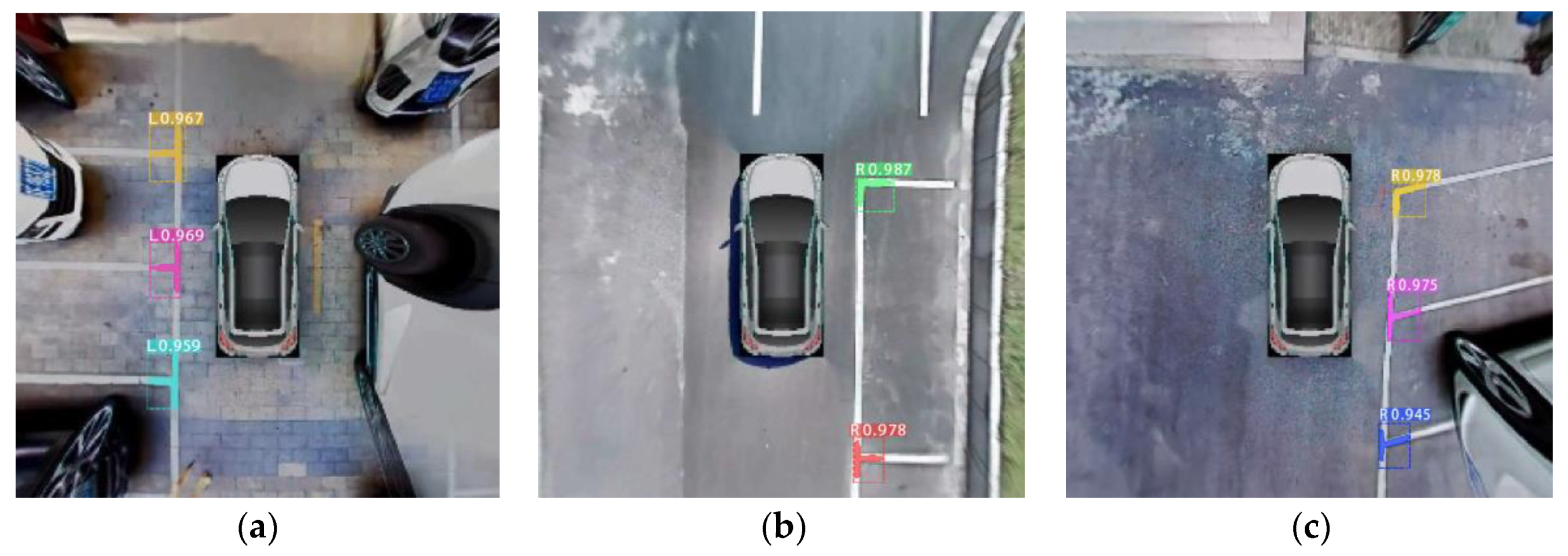
AVM images with marking-points detected by Mask R-CNN. (a) Vertical parking slots; (b) parallel parking slots; (c) slanted slots.
Figure 16.
AVM images with marking-points detected by Mask R-CNN. (a) Vertical parking slots; (b) parallel parking slots; (c) slanted slots.

Figure 17.
Detection process of parking guidelines and parallel lines. (a) AVM image; (b) mask of marking-points; (c) after corroding and dilating; (d) line detection; (e) the guideline and parallel line.
Figure 17.
Detection process of parking guidelines and parallel lines. (a) AVM image; (b) mask of marking-points; (c) after corroding and dilating; (d) line detection; (e) the guideline and parallel line.

Figure 18.
Marking-points detection performances among different methods.

Figure 19.
AVM images with different stitching effects. (a) From our experimental vehicle; (b) from the public dataset [49].
Figure 19.
AVM images with different stitching effects. (a) From our experimental vehicle; (b) from the public dataset [49].

Figure 20.
Loss of Mask R-CNN models with different training datasets.

Figure 21.
AVM images with parking slots detected by Mask R-CNN. (a–f) From the experimental vehicle; (g–i) from the public dataset [49].
Figure 21.
AVM images with parking slots detected by Mask R-CNN. (a–f) From the experimental vehicle; (g–i) from the public dataset [49].


Table 1.
Marking-points detection speed among different methods.
| Method | Speed (fps) |
|---|---|
| Mask R-CNN | 2 |
| Faster R-CNN | 7 |
| SSD | 18 |
| YOLO v1 | 22 |
Table 2.
Slot-detection performance among different methods.
| Method | SLOT | Accuracy | Precision | Recall | F1 Score |
|---|---|---|---|---|---|
| M1 | 256 | 89.5% | 89.3% | 90.4% | 89.8% |
| M2 | 256 | 90.2% | 91.2% | 88.7% | 89.9% |
| M3 | 256 | 93.4% | 94.5% | 92.7% | 93.5% |
| Method in [16] | 256 | 88.8% | 86.9% | 87.3% | 87.0% |
| Faster R-CNN [37] | 256 | 82.2% | 82.6% | 80.9% | 81.7% |
| Corner-based [23] | 256 | 70.5% | 74.3% | 72.4% | 73.3% |
| Line-based [26] | 256 | 77.8% | 80.3% | 75.2% | 77.6% |
© 2020 by the authors. Licensee MDPI, Basel, Switzerland. This article is an open access article distributed under the terms and conditions of the Creative Commons Attribution (CC BY) license (http://creativecommons.org/licenses/by/4.0/).
Share and Cite
MDPI and ACS Style
Jiang, S.; Jiang, H.; Ma, S.; Jiang, Z. Detection of Parking Slots Based on Mask R-CNN. Appl. Sci. 2020, 10, 4295. https://0-doi-org.brum.beds.ac.uk/10.3390/app10124295
AMA Style
Jiang S, Jiang H, Ma S, Jiang Z. Detection of Parking Slots Based on Mask R-CNN. Applied Sciences. 2020; 10(12):4295. https://0-doi-org.brum.beds.ac.uk/10.3390/app10124295
Chicago/Turabian StyleJiang, Shaokang, Haobin Jiang, Shidian Ma, and Zhongxu Jiang. 2020. "Detection of Parking Slots Based on Mask R-CNN" Applied Sciences 10, no. 12: 4295. https://0-doi-org.brum.beds.ac.uk/10.3390/app10124295
Note that from the first issue of 2016, this journal uses article numbers instead of page numbers. See further details here.