High-Power Broadband Frequency Chirped Intensity-Modulated Single-Frequency 1064-nm Laser


1
School of Optics and Photonics, Beijing Institute of Technology, Beijing 100081, China
2
Beijing Key Laboratory for Precision Optoelectronic Measurement Instrument and Technology, Beijing 100081, China
*
Author to whom correspondence should be addressed.
Appl. Sci. 2020, 10(13), 4450; https://0-doi-org.brum.beds.ac.uk/10.3390/app10134450
Submission received: 11 June 2020
/
Revised: 23 June 2020
/
Accepted: 26 June 2020
/
Published: 28 June 2020
(This article belongs to the Collection Optical Design and Engineering)
Abstract
:Optical carried microwave radar (OCMR), combining the advantages of lidar and microwave radar, uses an intensity-modulated laser beam as the medium to detect the distance and velocity of objects. In order to achieve a high ranging resolution at long distance, a high-power frequency chirped intensity-modulated light source at a 1064-nm wavelength was developed. A low-power narrow-linewidth 1064-nm laser beam was input to a Mach-Zehnder electro-optic modulator (EOM), and the frequency of the EOM was tuned from 10 MHz to 2.1 GHz. The output from the EOM was coupled to a laser-diode-pumped ytterbium-doped fiber amplifier (YDFA). A maximum output power of 29.5 W was achieved from the YDFA. We measured the frequency characteristics of the modulated laser beams before and after amplification, respectively. The amplification process did not bring any obvious degeneration of the modulation in terms of the bandwidth, frequency stability, chirping linearity, and modulation depth. Our research presents a new approach of obtaining a high-power broad-band intensity-modulated light source for OCMR.
1. Introduction
Optical carried microwave radar (OCMR) uses an intensity-modulated laser beam as the detection medium. The phase of the modulated returned signal is used to resolve the distance of the object to the transmitter and velocity of the detected objects. OCMR has high spatial resolution as lidar; at the same time, the modulated beam has stronger resistance to atmospheric turbulence and scattering than conventional lidar [1,2,3,4]. However, when OCMR is applied for ranging, there is a contradiction between the high ranging resolution, which requires a high modulation frequency, and the long unambiguous distance, which requires a low modulation frequency. The frequency domain reflectometry (FDR) technique can decouple the dependence of the range resolution and unambiguous range of hybrid lidar-radar systems and has since been used in a wide variety of applications where a large unambiguous range and high precision are desired [5,6].
Broadband frequency chirping intensity modulation of the laser beam was obtained with Mach-Zehnder electro-optic modulator(EOM) [7,8] and applied in an amplitude modulation (AM) lidar system by X. Yu et al. The chirped frequency was 80–280 MHz, the scanning period was 200 μs, and the range accuracy reached 0.8 m [9]. However, in the existing AM radar system, the output power of the transmitter was generally lower than 100 mW, even though a highly sensitive photon counting detector was used, and the ranging distance was limited by the low power of the lidar transmitter [10,11,12]. In order to apply FDR technology in long-distance ranging and detection, an intensity-modulated light source with high-power broad-band frequency chirping is desired.
In this paper, we present a new approach of obtaining high-power broad-band intensity-modulated light source based on modulation and amplification. A low-power light source with a narrow linewidth was modulated via a Mach Zehnder EOM. The output from the EOM was amplified via a two-stage ytterbium-doped fiber amplifier (YDFA). The modulation depth and frequency chirping linearity before and after amplification are discussed.
2. Application Background of Broadband Chirped Modulation in FDR
In the FDR method, a stepped frequency modulation is applied to the laser transmitter. The receiver records the magnitude and phase of the return signal at each frequency step, yielding the frequency response of the channel. Range information is retrieved by applying the inverse fast Fourier transform (IFFT). The range resolution is determined by the frequency chirping bandwidth while the unambiguous range is decided by the frequency step or frequency resolution of the modulation.
Suppose that the total modulation bandwidth is B, and the frequency response of the detected objects and surroundings are acquired at a frequency increment of Δf. The unambiguous range and range precision are simply expressed as [13]:
and:
where is the speed of light in the medium. From Equation (1) and Equation (2), one could infer that in order to have a long unambiguous range and high ranging resolution, wideband frequency chirping with a precise frequency resolution is needed for the light source.
Linear frequency modulated (LFM) signal is used to modulate the laser to obtain chirped intensity-modulated light. The frequency expression of the LFM signal is [14,15]:
where , B, and T are the initial frequency, bandwidth, and period of chirping in time, respectively.
The signal in Equation (3) is added at an EOM driver and used to modulate the intensity of the input laser to the EOM; the output from the EOM has an intensity expression as:
where A, , and are the amplitude, frequency, and phase of the input laser, respectively.
3. Theoretical Optimization of Diode Laser Pumped YDFA
The modulated laser beam was amplified by an YDFA. The rate equations of the pump and signal light in a gain fiber are as follows [16]:
where and are the power of the pump and signal at a distance of z. and are the cross-section areas of the emission and absorption of the pump light. and are the cross-section areas of the emission and absorption of the signal light. and are the absorption coefficients of the pump light and signal light. and are the overlap factors of the pump light and signal light, respectively. is the doping concentration of Yb3+ and is the concentration of upper energy-level particles, which has the expression [17,18]:
where and are the optical frequencies of the pump and signal, and is the Planck constant. is the lifetime of upper energy-level particles, and is the cross-section of the fiber core, respectively.
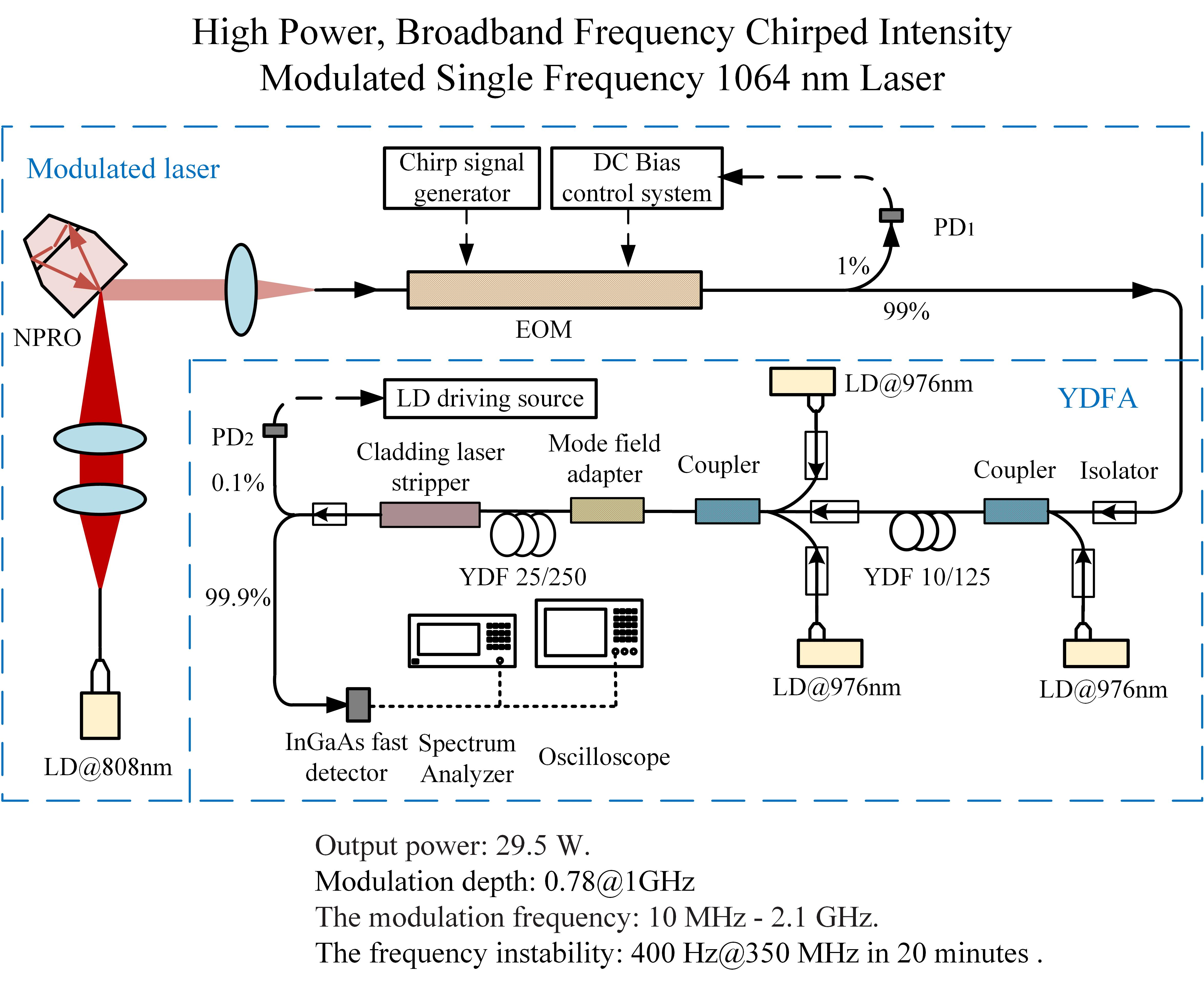
A double-clad fiber with a 0.5% ytterbium-doping concentration was used as the gain fiber. The core diameter of the gain fiber was 25 μm and the inner cladding diameter was 250 μm. Figure 1 shows the dependence of the amplified power with respect to the fiber length at different pumps and signal powers. It is shown that at a certain pump power, there is an optimum fiber length, and the optimum fiber length increases slightly with the increase of the pump power. In our system, the maximum pump power available was 40 W, and the output curve is flat from 12 to 15 m, so we chose 12 m as the fiber length. On the other hand, the input signal also contributes to the final amplified output. If the signal power is too small, even if the pump power is very high, the weak signal cannot extract the gain stored in the fiber and it is difficult to obtain a high power output. As the modulated laser signal had only 10.4 mW power, we decided to use a two-stage amplifier structure. The first stage amplified the signal light power to the watt level before going to the second stage of amplification.
4. Experimental Setup
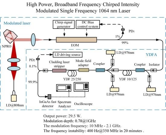
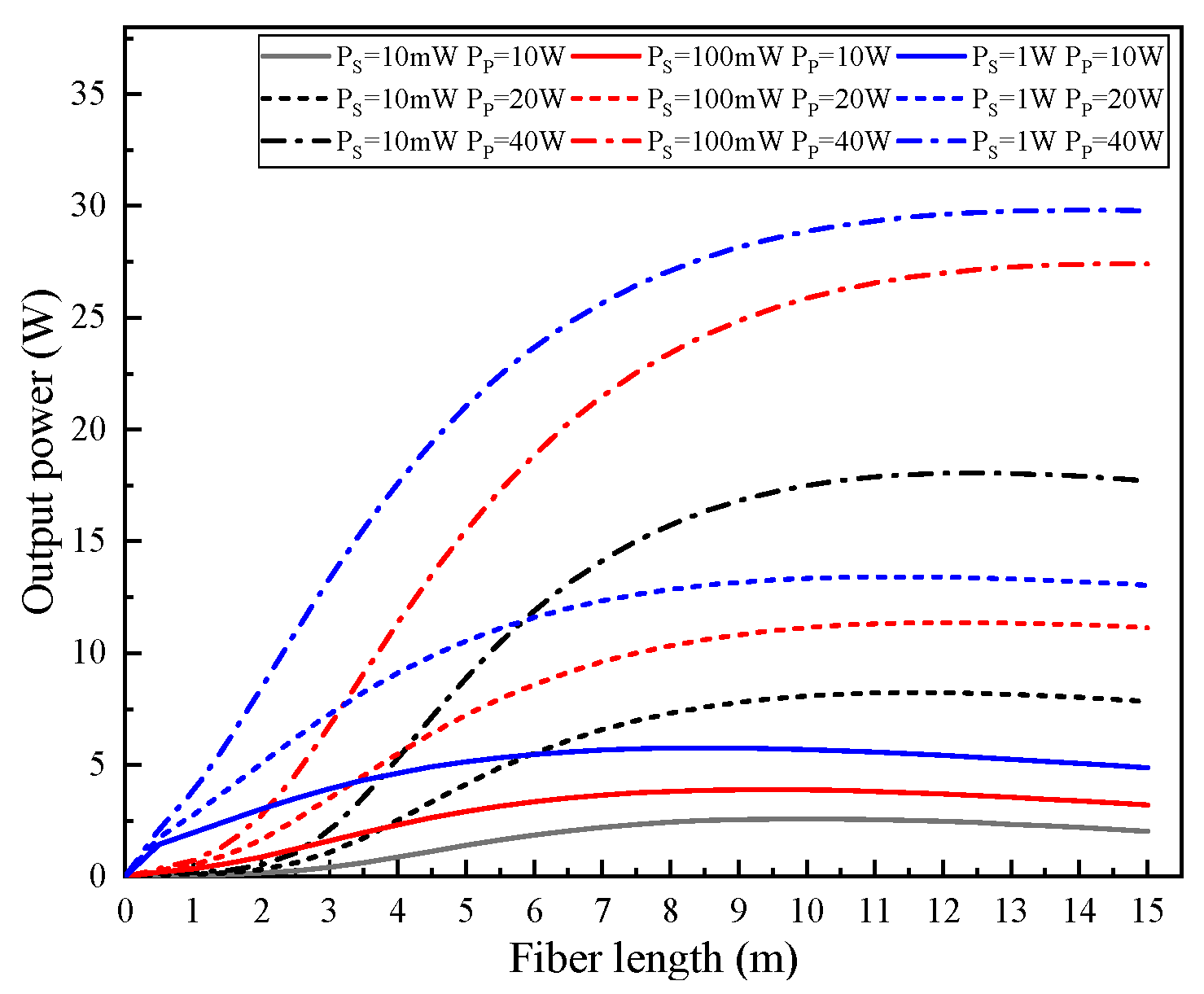
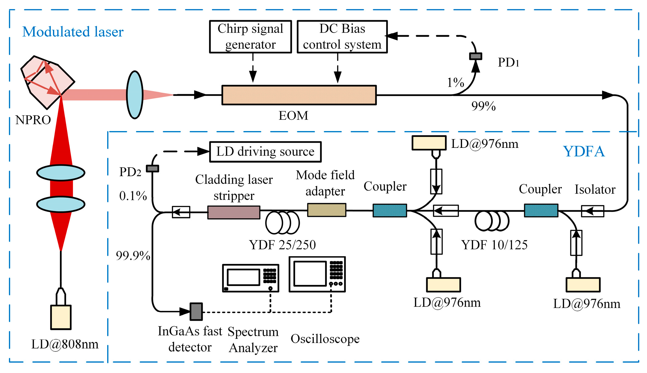
Figure 2 shows the experimental setup. The system used a non-planar ring oscillator (NPRO) single-frequency laser as the seed source [19]. The output laser was modulated via an EOM (CONQUER: KG-AM-1064-10G, Beijing, China). The maximum optical power input to the EOM was 50 mW.
A frequency chirping signal was loaded into the EOM driver. The modulation frequency was tuned from 10 MHz to 2.1 GHz. A bias was used to ensure the Mach-Zehnder modulator operated. A low-frequency low-amplitude dither signal together with a bias voltage was injected into the modulator to ensure it operated stably. The modulated light was separated via a fiber splitter. Here, 1% of the output was directed to a photodetector (PD). The output from the PD was fed back to the DC bias controller to make sure that an appropriate bias voltage was loaded into the EOM to compensate the phase drift. It kept reading the output from the modulator and determined the condition of the bias voltage and the related error. A compensate bias voltage was applied afterwards according to the previous measurements. The bias voltage kept the work point of the modulator transfer function at a fixed position (phase shift) to minimize the second harmonic distortion. Here, 99% of the modulated light was directed to the fiber amplifier.
The modulated low-power laser beam was amplified by a two-stage optical fiber power amplifier. The first stage used a 5-m gain fiber (Nufern: LMA-YDF-10/125, Granby, CT, USA), and the available pump power of the first stage amplifier was 4 W. For the second-stage amplifier, a 12-m fiber (Nufern: LMA-YDF-25/250, Granby, CT, USA) was used. The pumping source was two 20-W laser diodes. A mode field adapter was used to match the different core diameters of the two gain fibers to reduce transmission loss. A pump stripper was used to filter the residual pump light in the inner cladding of the second gain fiber. Photoelectric feedback was a common method to suppress laser intensity noise. Here, 0.1% of the output was directed to a PD. After the electric signal of laser power fluctuation was processed by the feedback control circuit, the driving current of the pump light in the optical fiber amplification system was adjusted to achieve stable laser output.
5. Experimental Results and Discussions
5.1. Output Power and Spectrum
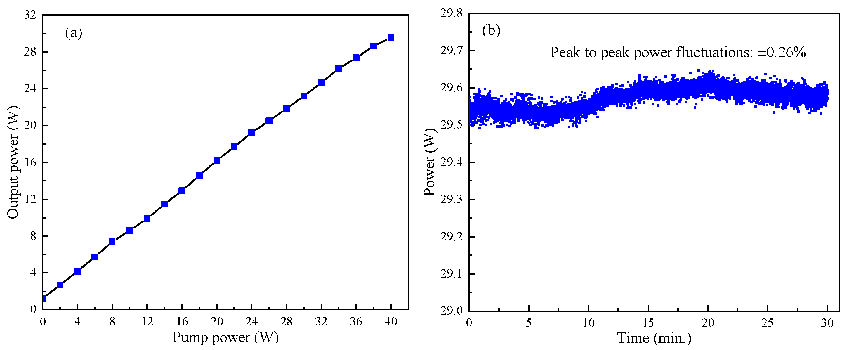
The input power to the EOM was 26 mW, and the output power of the chirped intensity modulated laser was 10.4 mW. After the first-stage optical fiber amplifier, the laser signal was amplified to 1.26 W. The output power of the second-stage amplifier versus pump power is shown in Figure 3a. A maximum output power of 29.5 W was obtained when 40 W of pump power was added to the second-stage amplifier. The optical-optical conversion efficiency was 70.6%. At the maximum output power, we measured the stability of the output power. As shown in Figure 3b, the long-term peak-to-peak power fluctuation was lower than ±0.26% over 30 min. Because of the feedback system of the YDFA, the output power stability was high.
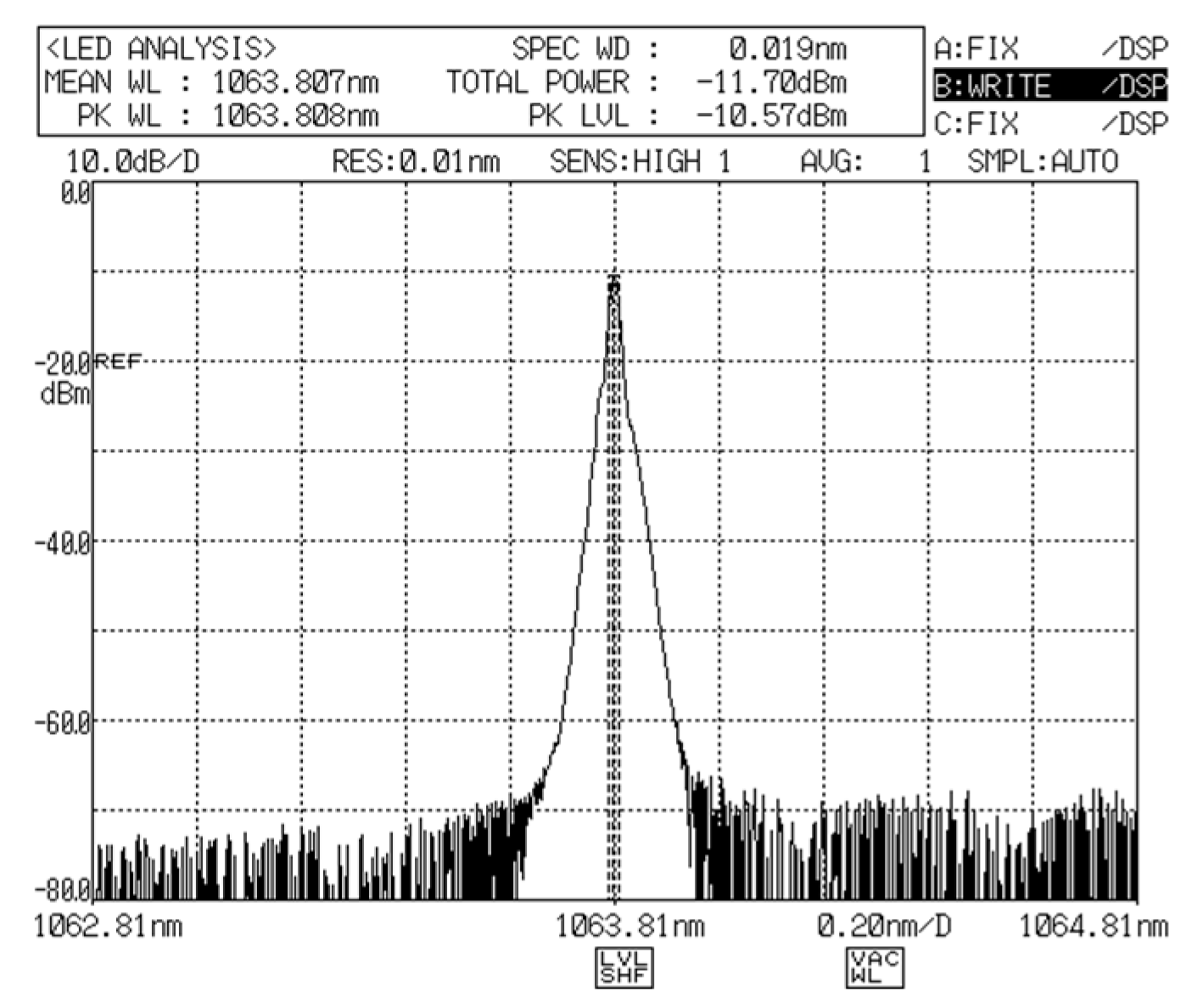
We measured the power spectrum for the amplifier output power by an optical spectrum analyzer (Yokogawa:AQ6317, Tokyo, Japan). As shown in Figure 4, the full width at half maximum of the spectrum is 0.019 nm, which is close to the resolution of the optical spectrum analyzer. Because the laser spectrum is very narrow, it is difficult for the spectrometer to measure the spectrum accurately.
5.2. Spectra of the Modulation
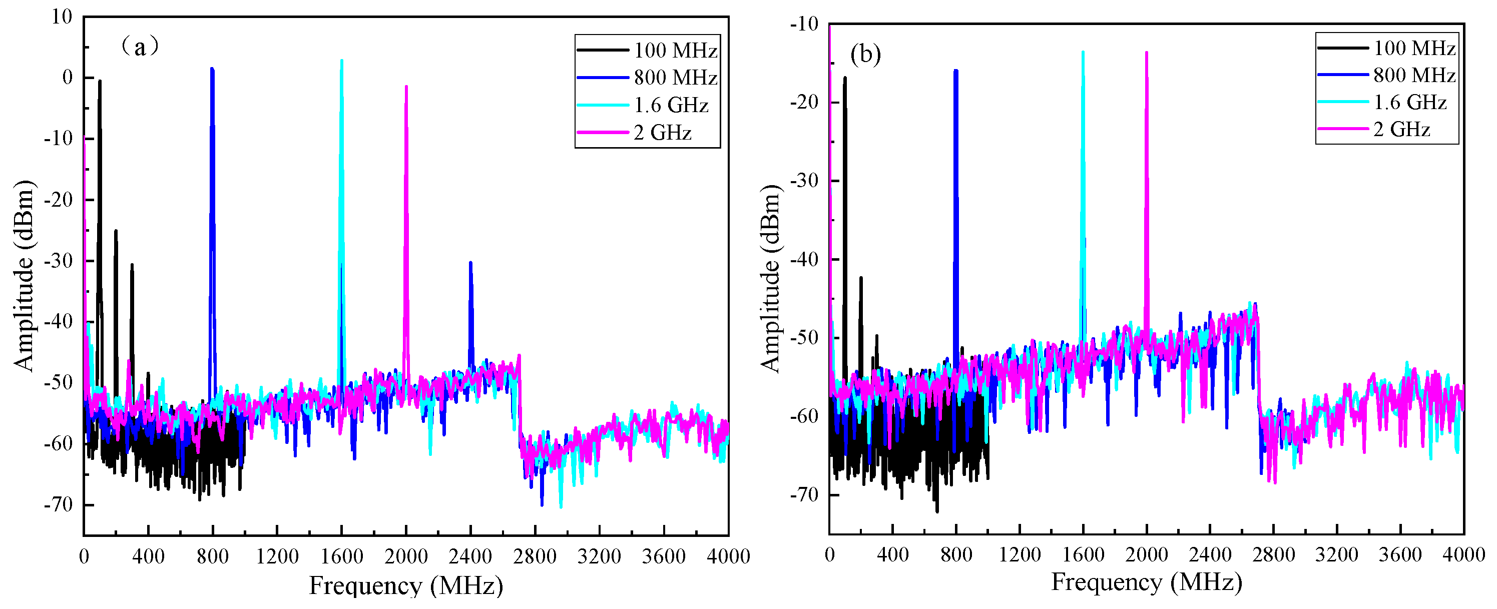
We fixed the modulation frequency added to the EOM at 0.1, 0.8, 1.6, and 2 GHz. A fast InGaAs detector (CONQUER: KG-PR-12G-B, Beijing, China) and a spectrum analyzer (Agilent:N1996A, Palo Alto, CA, USA) were used to obtain the spectra of the modulation of the light. Figure 5a shows the spectra of modulation before YDFA and Figure 5b shows the spectra of modulation after YDFA. When the modulation frequency was low, we can see many high harmonics; for instance, there were three high harmonics at 200, 300, and 400 MHz, respectively. When the modulation frequency was set to 100 MHz, this was the problem from the signal source. When the modulation frequency increased, less higher order harmonics could be seen, e.g., at 800 MHz, we could see two higher order harmonics at 1.6 and 2.4 GHz, but we could not see high-order harmonics at the fundamental modulation frequency of 1.6 and 2.0 GHz.
In the application of FDR, the high harmonic noise should be suppressed, and a specially designed filter will need to be added before the frequency sweeping signal is added to the EOM. After the modulated light was amplified by the YDFA, we saw less high-order harmonics in the spectra. When the modulated laser was transmitted in optical fiber, the absorption and scattering caused part of the loss. The scattering had gain characteristics and reduced the conversion efficiency. The higher the modulation frequency, the stronger the scattering intensity. Therefore, the high-order harmonic of the modulated laser was suppressed because of the smaller gain coefficient caused by the stronger scattering. The amplification process suppressed some high-order harmonic noise to a certain extent and the signal to noise ratio was improved.
The stability of the modulation frequency before and after amplification were measured with a frequency counter (Agilent: 53220A, Palo Alto, CA, USA) at 350 MHz. Figure 6 shows the results. The stabilities of the modulation frequency before and after the amplification within 20 min were 1.2 kHz and 400 Hz, respectively. There is no significant difference in stability at different modulation frequencies. Relaxation oscillation noise and environmental noise were suppressed by the feedback system of the YDFA, so the stability of the modulation frequency was effectively improved after amplification. In addition, the suppression of higher harmonics also improved the stability of the modulation frequency.
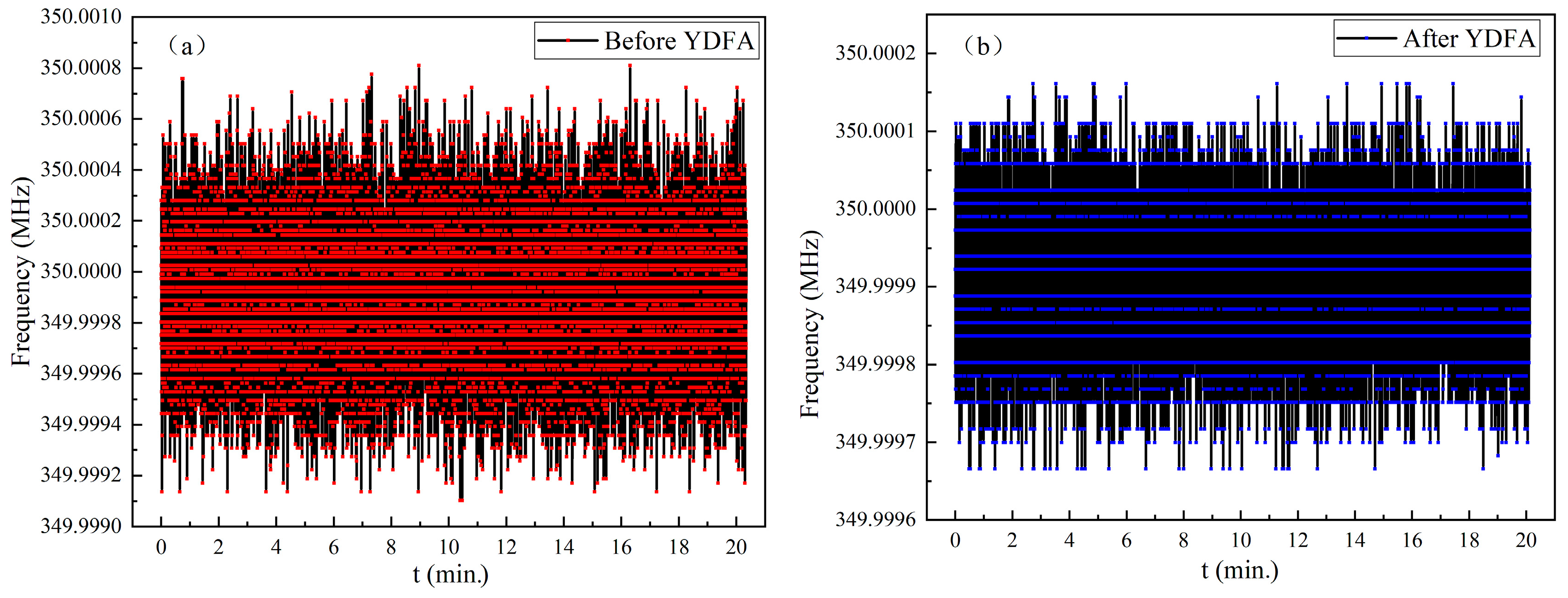
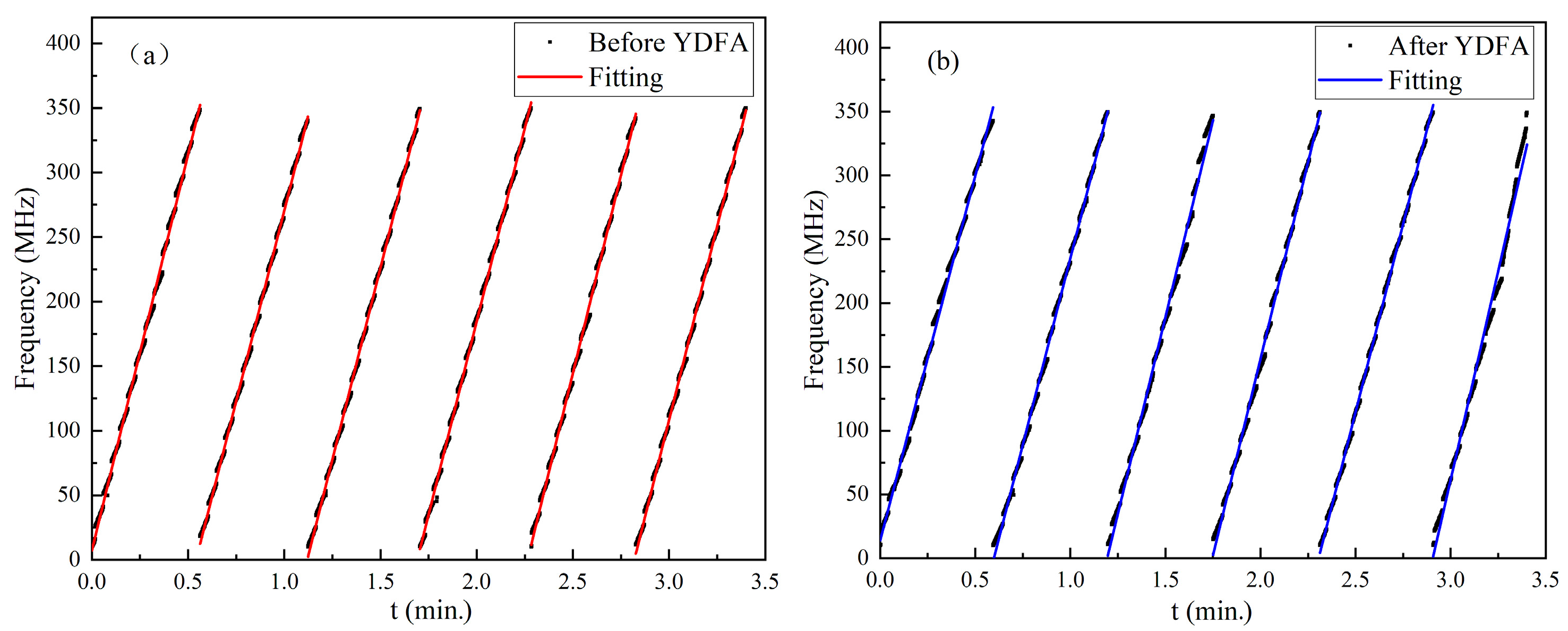
We measured the frequency sweeping linearities of the modulation. The measurement was limited to a frequency range from 10 to 350 MHz by the bandwidth of the frequency counter. The modulation frequency added to the EOM was linearly swept from 10 to 350 MHz with a step of 100 kHz, and the dwell time of each point was 10 ms. The modulated light beam was detected by a photo diode detector with a 12-GHz bandwidth and the frequency of the modulation was counted by the frequency meter. In total, 3400 frequency points were recorded in 34 s. The frequency sweeping was repeated within 3.5 min of the measuring time. Figure 7a and b show the time-dependent curves of the modulation frequency before and after YDFA, respectively. The solid lines are linear fits of the measured points. The average linearities of the frequency sweeping with respect to time in six measuring periods were 0.9989 and 0.9966 before and after amplification, respectively. One can see that the amplification did not induce obvious degeneration of the linearity of the frequency sweeping. The maximum dwell point of LFM signal generated by the signal source was 65,535, so the maximum frequency resolution at the 2-GHz modulation bandwidth was 30.5 kHz, corresponding to an unambiguous range of 2.46 km and ranging resolution of 3.75 cm in the air.
5.3. Modulation Depth
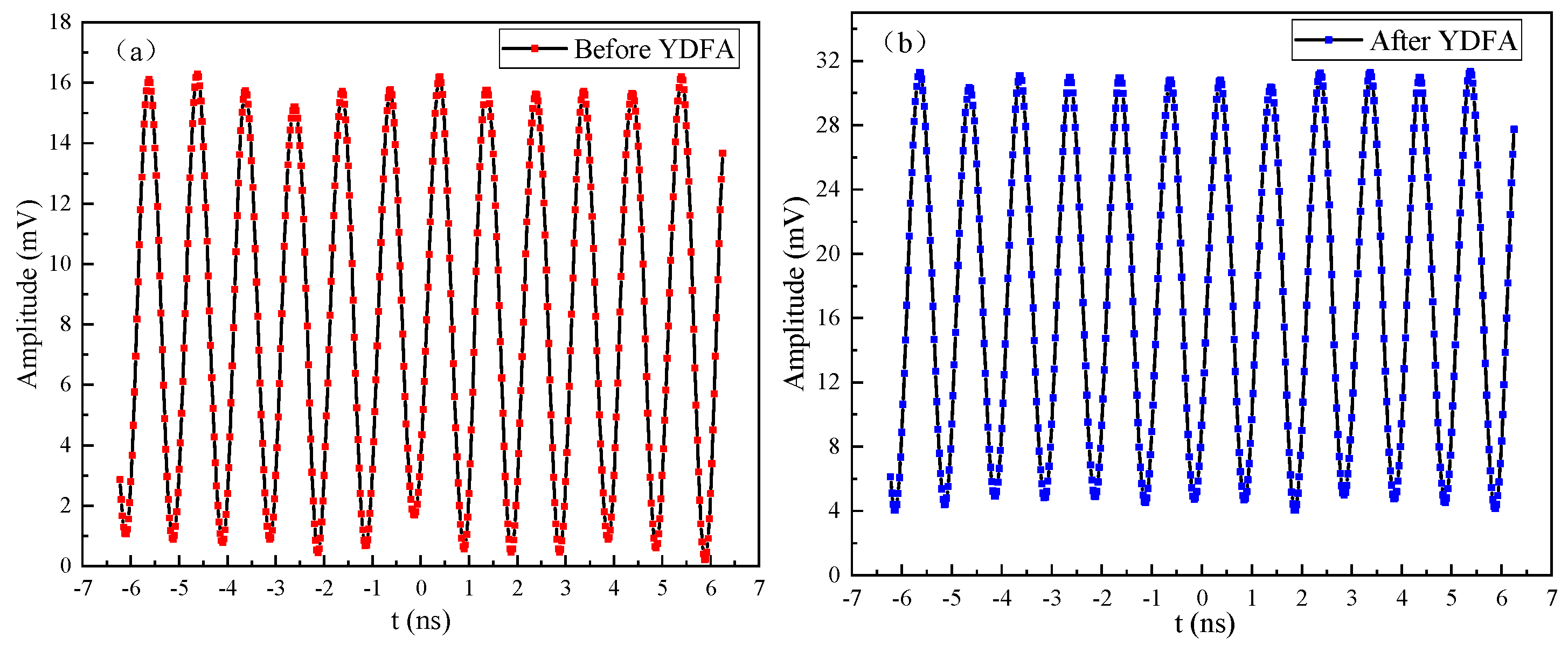
In order to compare the modulation depth before and after amplification. The modulation curves measured in the time domain with an oscilloscope are presented in Figure 8. When the modulation frequency was fixed at 1 GHz, the modulation depth decreased from 0.88 to 0.78 after amplification. The modulation waveform was smoother after amplification, as the higher order harmonics of the modulation frequency were suppressed. The decrease of the modulation depth may be due to a high spontaneous emission in the fiber amplifier. When the modulation frequency increases from 10 MHz to 1 GHz, the modulation depth decreases from 1 to 0.78.
6. Conclusions
In order to apply FDR technology in long-distance ranging and detection, a high-power broadband frequency chirped intensity-modulated single-frequency 1064-nm light source was developed. The modulation frequency was chirped from 10 MHz to 2.1 GHz. The modulated laser beam was amplified to 29.5 W by an YDFA. The peak-to-peak power fluctuation lower than ±0.26% over 30 min was recorded. The amplification process could suppress some high-order harmonic noises of the modulation, and the stability of the modulation frequency was improved. The frequency modulation linearity with respect to time was 0.9966 on average when the modulation frequency was tuned from 10 to 350 MHz. The frequency instability was less than 400 Hz for 20 min at a modulation frequency of 350 MHz. When the modulation frequency was 1 GHz, a modulation depth of 0.78 after amplification was measured. Since the modulation bandwidth of the EOM can reach tens of GHz, the frequency chirping bandwidth is mainly determined by the signal added to EOM. By increasing the bandwidth of the signal source, the modulation bandwidth can be easily increased for this high-power intensity-modulated light source. This light source has applications in hybrid lidar-radar with high ranging precision.
Author Contributions
Conceptualization, methodology, investigation, resources, S.Y., X.W. and Z.L.; data curation, writing—original draft preparation, K.L.; writing—review and editing, S.Y.; supervision, project administration, S.Y., X.W.; funding acquisition, S.Y., and Z.L. All authors have read and agreed to the published version of the manuscript.
Funding
This research was funded by National Natural Science Foundation of China under grant No. 61835001, 61875011.
Conflicts of Interest
The authors declare no conflict of interest.
References
- Vercesi, V.; Onori, D.; Laghezza, F.; Scotti, F.; Bogoni, A.; Scaffardi, M. Frequency-agile dual-frequency lidar for integrated coherent radar-lidar architectures. Opt. Lett. 2015, 40, 1358–1361. [Google Scholar] [CrossRef] [PubMed]
- Onori, D.; Scotti, F.; Scaffardi, M.; Bogoni, A.; Laghezza, F. Coherent Interferometric Dual-Frequency Laser Radar for Precise Range/Doppler Measurement. J. Lightwave Technol. 2016, 34, 4828–4834. [Google Scholar] [CrossRef]
- Diaz, R.; Chan, S.C.; Liu, J.M. Lidar detection using a dual-frequency source. Opt. Lett. 2007, 31, 3600–3602. [Google Scholar] [CrossRef] [PubMed] [Green Version]
- Kameyama, S.; Imaki, M.; Hirano, Y.; Ueno, S.; Kawakami, S.; Sakaizawa, D.; Nakajima, M. Performance improvement and analysis of a 1.6 μm continuous-wave modulation laser absorption spectrometer system for CO2 sensing. Appl. Opt. 2011, 50, 1560–1569. [Google Scholar] [CrossRef] [PubMed]
- Macdonald, R.I. Frequency domain optical reflectometer. Appl. Opt. 1981, 20, 1840–1844. [Google Scholar] [CrossRef] [PubMed]
- Kingsley, A.S.; Davies, D.E.N. OFDR Diagnostics for Fiber/Integrated Optic Systems and High Resolution Distributed Fiber Optic Sensing. In Proceedings of the SPIE Fiber Optic and Laser Sensors III, San Diego, CA, USA, 20–23 August 1985; Volume 0566, pp. 265–275. Available online: https://www.spiedigitallibrary.org/conference-proceedings-of-spie/0566/0000/OFDR-Diagnostics-For-Fiber-Integrated-Optic-Systems-And-High-Resolution/10.1117/12.949800.short?SSO=1 (accessed on 11 June 2020).
- Noguchi, K. Highly efficient 40-GHz bandwidth Ti:LiNbO3 optical modulator employing ridge structure. IEEE Photonic. Tech. Lett. 2002, 5, 52–54. [Google Scholar] [CrossRef]
- Maegami, Y.; Cong, G.; Ohno, M.; Okano, M.; Iton, K.; Nishiyama, N.; Arai, S.; Yamada, K. High-efficiency strip-loaded waveguide-based silicon Mach-Zehnder modulator with vertical p-n junction phase shifter. Opt. Express 2017, 25, 31407–31416. [Google Scholar] [CrossRef] [PubMed]
- Yu, X.; Hong, G.L.; Ling, Y.; Shu, R. Homodyne Detection of Distance and Velocity by Chirped-Amplitude Modulated Lidar. Acta Optic. Sin. 2011, 31, 0606002. [Google Scholar]
- Zhang, Z.; Zhang, J.; Wu, L.; Zhang, Y.; Zhao, Y.; Su, J. Photon-counting chirped amplitude modulation lidar using a smart premixing method. Opt. Lett. 2013, 38, 4389–4392. [Google Scholar] [CrossRef] [PubMed]
- Redman, B.; Ruff, W.; Giza, M. Photon counting chirped AM ladar: Concept, simulation, and initial experimental results. Proc. SPIE Int. Soc. Opt. Eng. 2006, 6214, 1–9. [Google Scholar]
- Zhang, Z.; Wu, L.; Zhang, Y.; Zhao, Y. Method to improve the signal-to-noise ratio of photon-counting chirped amplitude modulation ladar. Appl. Opt. 2013, 52, 274–279. [Google Scholar] [CrossRef] [PubMed]
- Illig, D.W.; Jemison, W.D.; Rumbaugh, L.; Lee, R.; Laux, A.; Mullen, L. Enhanced hybrid lidar-radar ranging technique. In Proceedings of the IEEE Conference on Oceans, San Diego, CA, USA, 23–27 September 2013; pp. 1–9. [Google Scholar]
- Samarah, A. A 320 MHz Digital Linear Frequency Modulated Signal Generator for Radar Applications Using FPGA Technology. In Proceedings of the IEEE Conference on Computational Intelligence & Communication Networks, Bhopal, India, 14–16 November 2014; pp. 966–972. [Google Scholar]
- Milewsk i, A.; Sedek, E.; Gawor, S. Amplitude Weighting of Linear Frequency Modulated Chirp Signals. In Proceedings of the IEEE Conference on Signal Processing and Communications Applications, Eskisehir, Turkey, 11–13 June 2007; pp. 383–386. [Google Scholar]
- Cheng, L.J.; Yang, S.H.; Zhao, C.M.; Zhang, H.Y. High power wideband radio frequency intensity modulated continuous wave laser. Acta Phys. Sin. 2018, 67, 034203. [Google Scholar]
- Xiao, Q.; Yan, P.; Li, D.; Sun, J.; Wang, X.; Huang, Y.; Gong, M. Bidirectional pumped high power Raman fiber laser. Opt. Express 2016, 24, 6758–6768. [Google Scholar] [CrossRef] [PubMed]
- Zhang, H.; Xiao, H.; Zhou, P.; Wang, X.; Xu, X. High power Yb-Raman combined nonlinear fiber amplifier. Opt. Express 2014, 22, 10248–10255. [Google Scholar] [CrossRef] [PubMed]
- Kane, T.J. Monolithic, unidirectional single-mode Nd:YAG ring laser. Opt. Lett. 1985, 10, 65–67. [Google Scholar] [CrossRef] [PubMed]
Figure 1.
Numerical calculation of the dependence of the amplified output power on the fiber length at different pump and signal powers.
Figure 1.
Numerical calculation of the dependence of the amplified output power on the fiber length at different pump and signal powers.

Figure 2.
Diagram of the experimental setup of the chirped intensity-modulated laser and the fiber power amplifier.
Figure 2.
Diagram of the experimental setup of the chirped intensity-modulated laser and the fiber power amplifier.

Figure 3.
(a) Output power of the second-stage amplifier versus pump power; (b) Power stability within 30 min.
Figure 3.
(a) Output power of the second-stage amplifier versus pump power; (b) Power stability within 30 min.

Figure 4.
Power spectrum for the amplifier output power.

Figure 5.
Spectrum of the modulation (a) before and (b) after amplification.

Figure 6.
Stability of the spectra of modulation (a) before and (b) after amplification.

Figure 7.
Frequency sweeping linearity of modulation (a) before and (b) after amplification.

Figure 8.
Modulation waveform (a) before and (b) after amplification.

© 2020 by the authors. Licensee MDPI, Basel, Switzerland. This article is an open access article distributed under the terms and conditions of the Creative Commons Attribution (CC BY) license (http://creativecommons.org/licenses/by/4.0/).
Share and Cite
MDPI and ACS Style
Li, K.; Yang, S.; Wang, X.; Li, Z. High-Power Broadband Frequency Chirped Intensity-Modulated Single-Frequency 1064-nm Laser. Appl. Sci. 2020, 10, 4450. https://0-doi-org.brum.beds.ac.uk/10.3390/app10134450
AMA Style
Li K, Yang S, Wang X, Li Z. High-Power Broadband Frequency Chirped Intensity-Modulated Single-Frequency 1064-nm Laser. Applied Sciences. 2020; 10(13):4450. https://0-doi-org.brum.beds.ac.uk/10.3390/app10134450
Chicago/Turabian StyleLi, Kun, Suhui Yang, Xin Wang, and Zhuo Li. 2020. "High-Power Broadband Frequency Chirped Intensity-Modulated Single-Frequency 1064-nm Laser" Applied Sciences 10, no. 13: 4450. https://0-doi-org.brum.beds.ac.uk/10.3390/app10134450
Note that from the first issue of 2016, this journal uses article numbers instead of page numbers. See further details here.