Cutting Force Prediction and Experiment Verification of Paper Honeycomb Materials by Ultrasonic Vibration-Assisted Machining


1
School of Mechanical Engineering, Xi’an Jiaotong University, Xi’an 710049, China
2
Shenzhen Research School, Xi’an Jiaotong University, Hi-Tech Zone, Shenzhen 518057, China
*
Author to whom correspondence should be addressed.
Appl. Sci. 2020, 10(13), 4676; https://0-doi-org.brum.beds.ac.uk/10.3390/app10134676
Submission received: 19 May 2020
/
Revised: 26 June 2020
/
Accepted: 3 July 2020
/
Published: 7 July 2020
(This article belongs to the Section Mechanical Engineering)
Abstract
:The disc-cutter is a finishing tool for the ultrasonic-cutting of paper honeycomb-core material. The cutting state directly affects the machining accuracy and surface quality of the workpiece. The cutting force is an important physical quantity and the cause of ultrasonic cutting defects of the honeycomb-core material. Due to differences in the mechanical properties and cutting performance of honeycomb-core materials and commonly used metal materials, existing metal-cutting-force models cannot be applied to the calculation of ultrasonic cutting forces in the processing of honeycomb-core materials. In response to this problem—combined with actual working conditions using the ABAQUS finite element analysis software—a finite element simulation model of the ultrasonic vibration-assisted cutting force of the disc-cutter on the honeycomb-core material was established, and the cutting curves and values were obtained. The experiment of ultrasonic vibration cutting of the disc-cutter proves that from the surface morphology of the honeycomb core, the milling-width has the greatest influence on the cutting force, and the cutting-depth has the smallest influence on the cutting force. The maximum error between the cutting force experimental results and the finite element simulation results under the same cutting conditions was 13.2%, which means that the established cutting-force finite element model is more accurate and can be used to predict the cutting in honeycomb ultrasonic vibration-assisted cutting-force value. Finally, based on the response surface method, a three-dimensional cutting force prediction model of the ultrasonic cutting honeycomb core of the disc-cutter was established by using the simulation model data. The results of this study can provide a useful basis for the improvement of cutting performance and processing efficiency in the processing of paper honeycomb-core materials.
1. Introduction
Honeycomb-core material is a kind of high-stiffness, light-quality, heat-resistant, impact-resistant, fatigue-resistant, good-insulating soundproof stays-engineering composite material. Zuhri, Gomet and Castaniea analyzed the mechanical properties and excellent qualities of honeycomb-core materials through theoretical modeling and experimental verification [1,2,3]. Alix and Tauhiduzzaman introduced honeycomb parts used in the aerospace field such as helicopter power plant fairings, large aircraft wings, liquid fuel barriers in rockets, etc. [4,5]. In order to meet the requirements of assembly and connection, the honeycomb-core material must be cut after it is formed. However, the honeycomb-core material is a typical difficult to machine material, it brings great challenges to the CNC machining of honeycomb-core material due to the particularity of honeycomb core structure and cutting mechanism. Rinker, Malek and Hohe proposed related process optimization methods for processing defects such as honeycomb core fracture and collapse, increased surface burrs and dust pollution during the CNC high-speed milling process of honeycomb core, which greatly reduces the performance of the honeycomb core structure and improves the product Safety and service life [6,7,8].
Oriented to the manufacturing requirements of honeycomb-core material parts, in view of the problems existing in CNC high-speed milling processing, scholars are constantly exploring new processing methods and improving the existing processing technology. Ultrasonic vibration-assisted cutting technology as a new advanced processing technology has been applied in the field of CNC machining of honeycomb core workpiece [9]. Compared with high speed milling, this machining method has significant advantages in machining accuracy, quality, efficiency and environmental friendliness [10,11]. In the ultrasonic vibration-assisted machining of honeycomb-core material, there still have surface damage problems such as core tearing and machining surface burr. There is little research on the ultrasonic vibration-assisted cutting force of the disc-cutter. Heimbs and Aminanda studied the failure behavior of the honeycomb core through experimental means and concluded that the cutting force is an important physical parameter that causes defects in the honeycomb core workpiece [12,13]. The research of rotating vibration cutting of honey comb core components with disc-cutter is only focusing on the test verification; mechanism study must be carried out to reveal the influence of the cutting parameters on machining quality. Potlkuri measured the elastic properties of the hexagonal honeycomb-core material through experiments [14]. Based on brittle fracture mechanics, Hu studied the cutting mechanism of the ultrasonic cutting of the honeycomb core with a sharp knife and derived a theoretical model of cutting force [15]. However, the entire process of ultrasonic vibration-assisted cutting of disk cutters is time-consuming, the processing quality is unstable, the surface burrs on the processing, and the core damage are still outstanding.
In order to solve the problem of cutting damage of the honeycomb core workpiece in ultrasonic vibration-assisted cutting, this study used finite element analysis software to establish a 3D honeycomb-core material model and a disc-cutter model according to the actual working conditions. A method of ultrasonically cutting the honeycomb-core material with a disk milling cutter is proposed. At the same time, the correctness of the finite element model is verified through experiments. The influence of process parameters on cutting quality was studied. At the same time, based on the response surface method, a simulation model was used to construct a cutting force prediction model for the honeycomb core of the disc-cutter ultrasonic machining, which provided a theoretical basis for the optimization of the cutting technology of the honeycomb-core material and the reasonable selection of processing parameters.
2. Establishment and Verification of Finite Element Simulation Model for Honeycomb Core Ultrasonic Vibration-Assisted Cutting
2.1. Disc-cutter Geometry Model
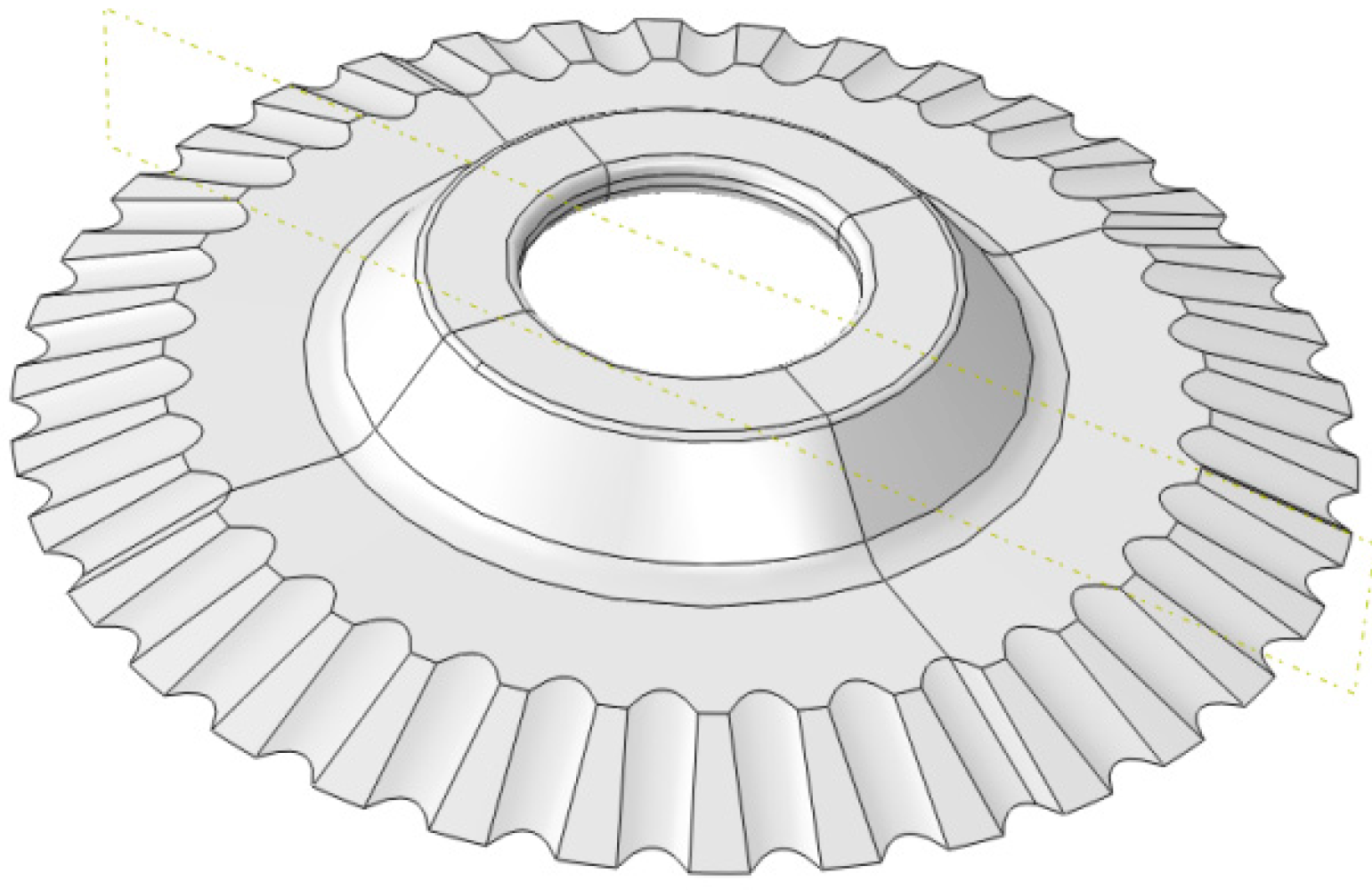
Due to the structure difference between Nomex honeycomb-core composite material and the metal material, a corresponding special tool must be used for machining, and the structural shape and geometric angle of the tool are greatly different from the metal cutter. Nomex honeycomb-core composites material can be machined due to the tool forms a sharp cutting edge with a small wedge angle, which is the key to the material being cut. The rotary-vibration-cutting disc-cutter model studied in this paper is shown in Figure 1. Due to the complex structure of the tool, the model was built by the CATIA V5R21 and imported into the ABAQUS, the geometric parameters of disc-cutter are shown in Table 1.
The tool material is W18Cr4 V, material density ρ = 7900 kg/m3, elasticity modulus E = 205 Gpa, Poisson’s ratio μ = 0.3. Due to the low hardness of the Nomex honeycomb-core material, the tool wear is neglected in the simulation, and the tool is defined as a rigid body.
2.2. Honeycomb Core Geometry Model and Material Model
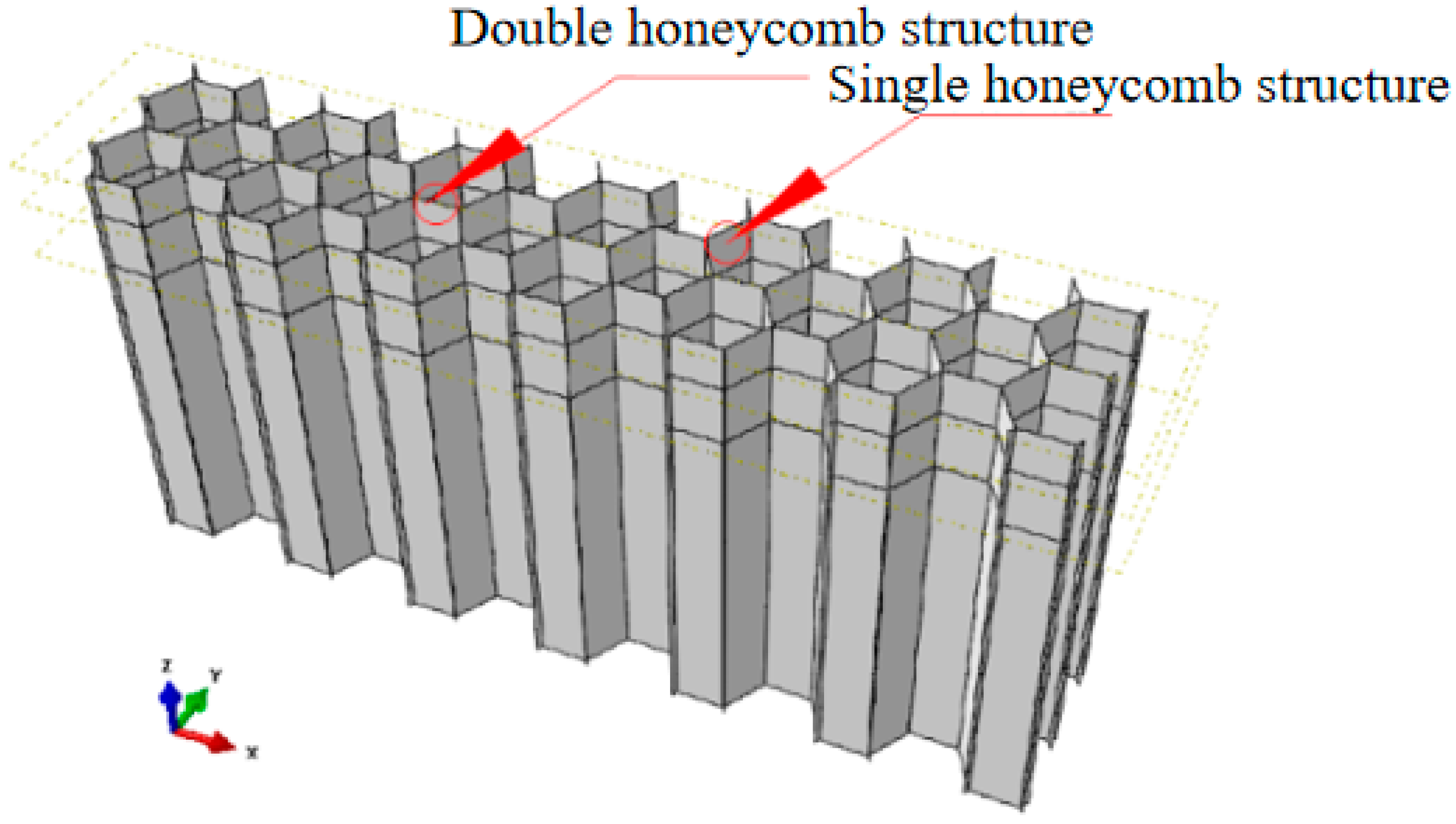
The honeycomb-core material is structurally different from the conventional metal-processing material. It is a porous thin-walled structure with a hexagonal shape, the hole has a side length of 3–6 mm and a single-layer-wall thickness of 0.05–0.15 mm. Honeycomb core geometry modeling is performed in ABAQUS/CAE, where a single core is drawn, then the entire sketch is completed by mirroring and arraying, and finally stretched vertically along the aperture according to the height of the desired honeycomb core. When the wall thickness of the shell unit is set, the thickness of the single layer is set to 0.1 mm, and the thickness of the double layer joint is 0.2 mm. The geometric model of the Nomex honeycomb-core composite material established in the finite element analysis is shown in Figure 2.
The main structure of Nomex honeycomb core is aramid paper. The molding of aramid paper material is made by arranging aramid fibers randomly distributed in XYZ direction in any ratio and combining them. Due to the flexibility and randomness of fiber arrangement, the mechanical properties of Nomex honeycomb-core materials cannot be directly measured by researchers using conventional measurement methods. To date, the more commonly used is derived from the empirical formula of the fiber modulus at random. The research shows that the mechanical properties of the aramid fiber in the vertical direction are basically consistent with the main direction of the material. In this paper, the honeycomb material and tool material used in cutting simulation processing The attributes are shown in Table 2 below.
2.3. Separation and Fracture Failure Criteria
The ultrasonic vibration-assisted cutting process of honeycomb-core material is the separation process of chip and workpiece under the action of blade and ultrasonic vibration-assisted. Therefore, the determination of chip separation and fracture failure criteria is critical to achieving finite element simulation of the honeycomb core cutting process. The separation criteria depend on the mechanical and physical properties of the material. Common separation criteria are geometric and physical criteria. The shear-failure criterion is applied in this study, which is provided by the finite element software. Depending on the plastic strain value of the element node reaches a predetermined critical value to determining failure occurs or not. By the calculation, when the destruction coefficient ω reaches the set value, the unit is considered to be “killed”, which means the material is destroyed and chips are formed. The value of the failure coefficient ω can be obtained from the following formula:
where is the equivalent plastic strain increment; is the total strain when the material is damaged; w is the shaping limit value or destruction coefficient.
2.4. Meshing, Boundary Conditions and Load Settings
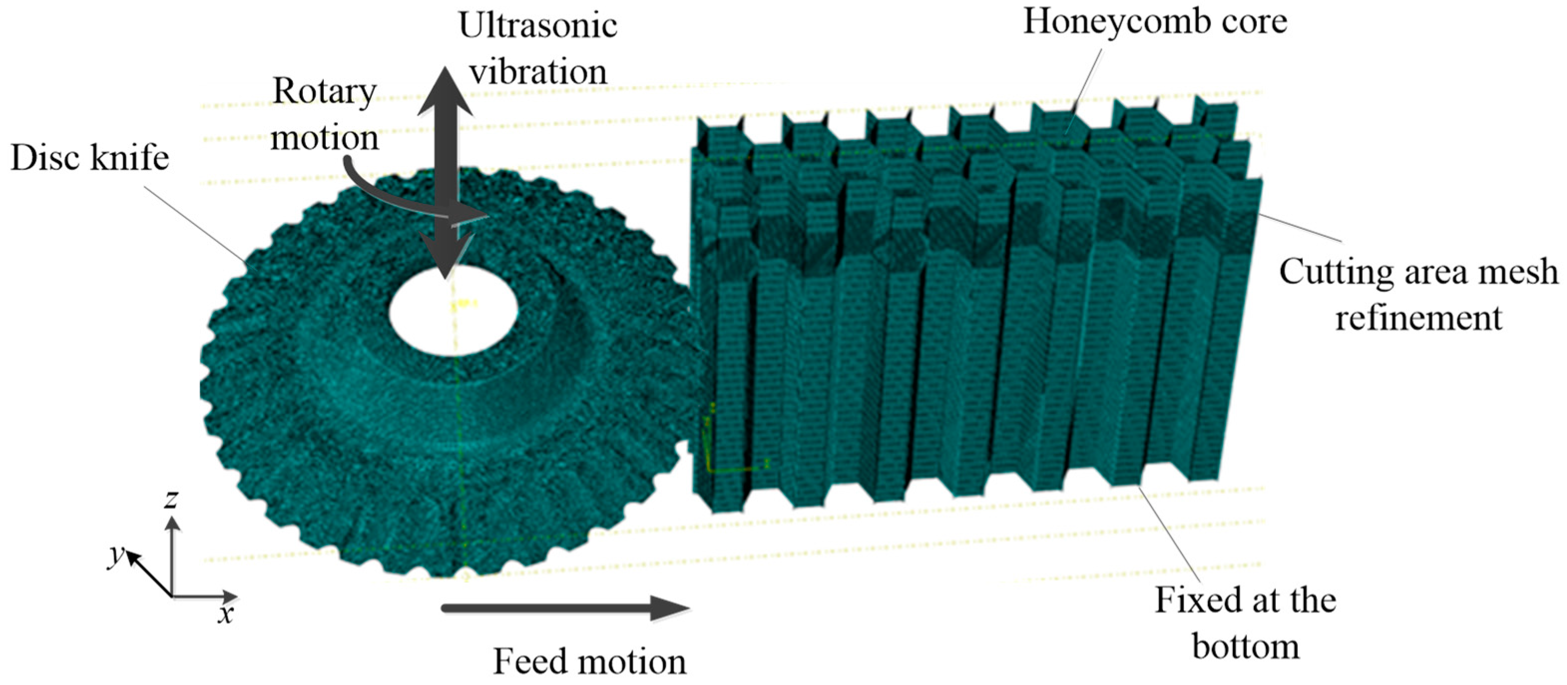
In this paper—based on the Hypermesh software—the honeycomb-core material in the processing path of the disc-cutter was locally refined and sharpened. The honeycomb core was is meshed with C3D8T eight-node thermal coupling hexahedron, and the disc-cutter uses C3D10MT ten-node thermal coupling second-order tetrahedron meshing. The divided honeycomb core is imported into ABAQUS. Since the calculation of cutting heat is considered, an explicit temperature–displacement algorithm is selected. Before the model is submitted to the calculation, carefully check the setting of nonlinear parameters that may lead to nonconvergence or difficult convergence, Such as material settings, contact settings, etc.
During the simulation, the disk cutter and the honeycomb core must be subjected to load and boundary condition constraints according to the actual working conditions. Since the stiffness of the disc-cutter is much greater than that of the honeycomb core, the cutter is used as a rigid body during the simulation. In terms of boundary constraints, due to the poor local strength of the honeycomb core, it is not possible to use the traditional method of holding. In actual working conditions, the part is held by vacuum suction through adhesive tape on the bottom surface of the part. In the simulation model, it is assumed that the part is held firmly. All joints on the bottom of the part are fully fixed.
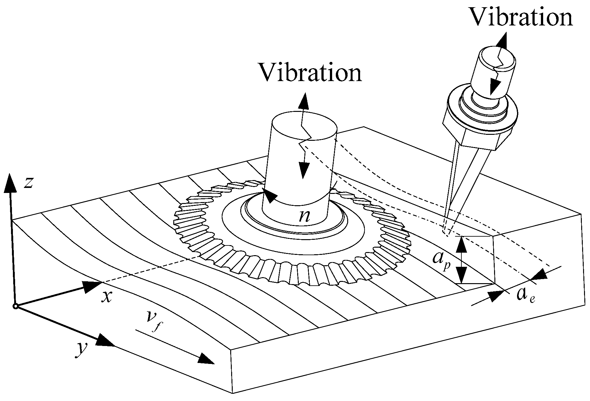
The disc-cutter has three directions of motion synthesis relative to the honeycomb material, which are the feed movement, rotary movement of the cutter along its cutting trajectory and the vibration of the cutter along its axis. Velocity/angular velocity was adopted in ABAQUS The disc-cutter defines the feed velocity (vf) along the x-axis and the rotary motion along the z-axis, while applying a reciprocating ultrasonic wave up and down to the periodic amplitude function of the Fourier series in the z-axis direction of the disc-cutter vibration. Set the initial temperature of parts, disc-cutter and environment to room temperature. The simulation model of Nomex honeycomb core with ultrasonic vibration of disc-cutter is shown in Figure 3.
In the direction of the z-axis of the tool, the vibration equation of any node of the disc-cutter during rotary-vibration-cutting is:
where A is the amplitude (μm); f is the frequency (Hz).
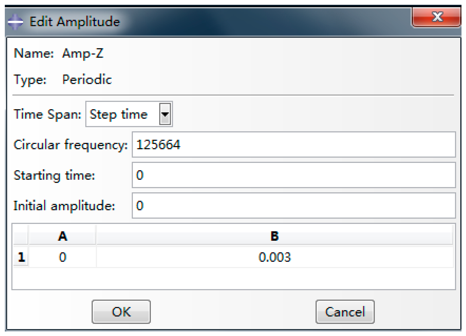
The periodic amplitude function in the formula is expressed by Fourier series, and loaded in ABAQUS in the form of Figure 4, the expression is:
where A0 is the initial amplitude (μm); ω is the circular frequency (rad/s); An is the coefficient of the cos function; Bn is the coefficient of the sin function.
2.5. Simulation Scheme Design
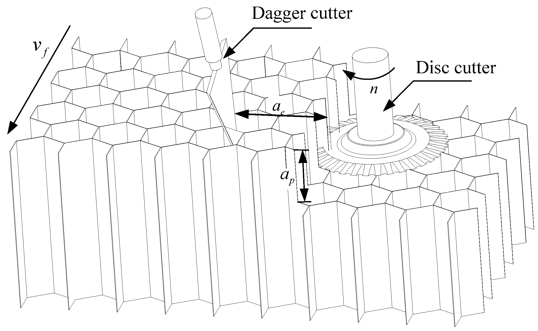
In actual cutting, the disc-cutter cannot cut with large margin in the radial direction without crushing chip, otherwise the residual material cannot be cut off, the workpiece will be pulled up and causing cutting damage. The disc-cutter must be processing according to the depth and width produced by knife cutting. The specific cutting is shown in Figure 5.
In order to ensure the feasibility of the experiment, first, use the knife cutter to produce the cutting thickness and width for disk cutter processing, and then use the disk cutter to machine the profile. The cutting process is shown in Figure 6.
In order to ensure the consistency of the cutting simulation and the cutting experiment parameters, as well as the accuracy of subsequent test verification. Since the follow-up test is verified on the designated ultrasonic processing equipment, the spindle speed and amplitude must be kept constant. According to the actual processing conditions on site, technicians usually adjust the cutting width range from 5 to 20 mm. The cutting depth ranges from 5 to 20 mm, and the feed speed ranges from 3000 to 6000 mm/min under the conditions of speed n = 1500 r/min and amplitude A = 30 μm, may wish to obtain the single-factor simulation program shown in Table 3 through reasonable design and planning.
3. Results
3.1. Simulation Results and Verification Analysis
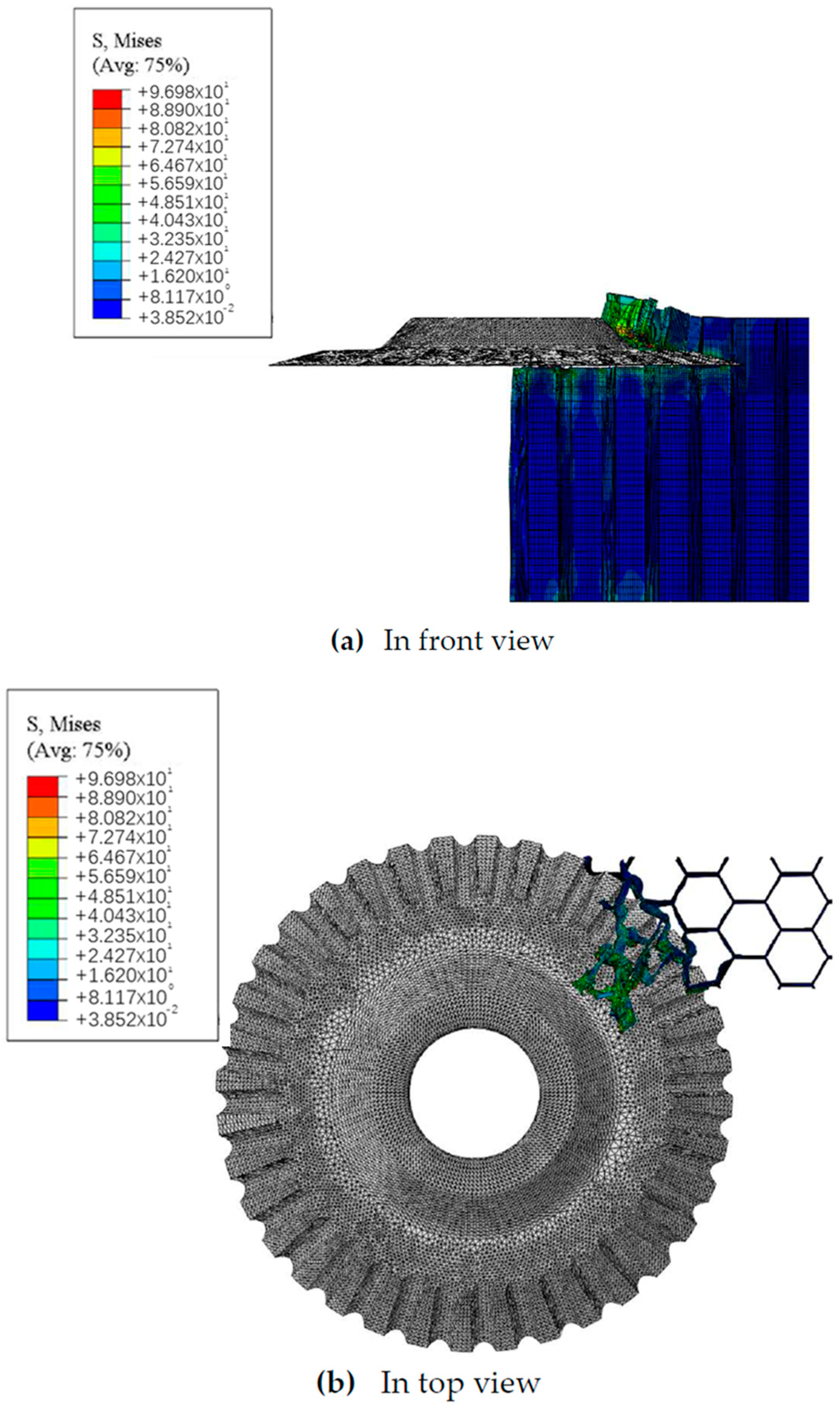
In addition to the above key links, the rotational vibration simulation analysis of the disc-cutter must set the field output results and historical output results in the software, such as stress, strain, displacement, energy, temperature, etc. At the same time, in order to improve the calculation efficiency, the honeycomb-core composite material is scaled by 5 times in the simulation to reduce the calculation time. The finite element simulation process of Nomex honeycomb-core composite disc-cutter rotating vibration cutting is shown in Figure 7.
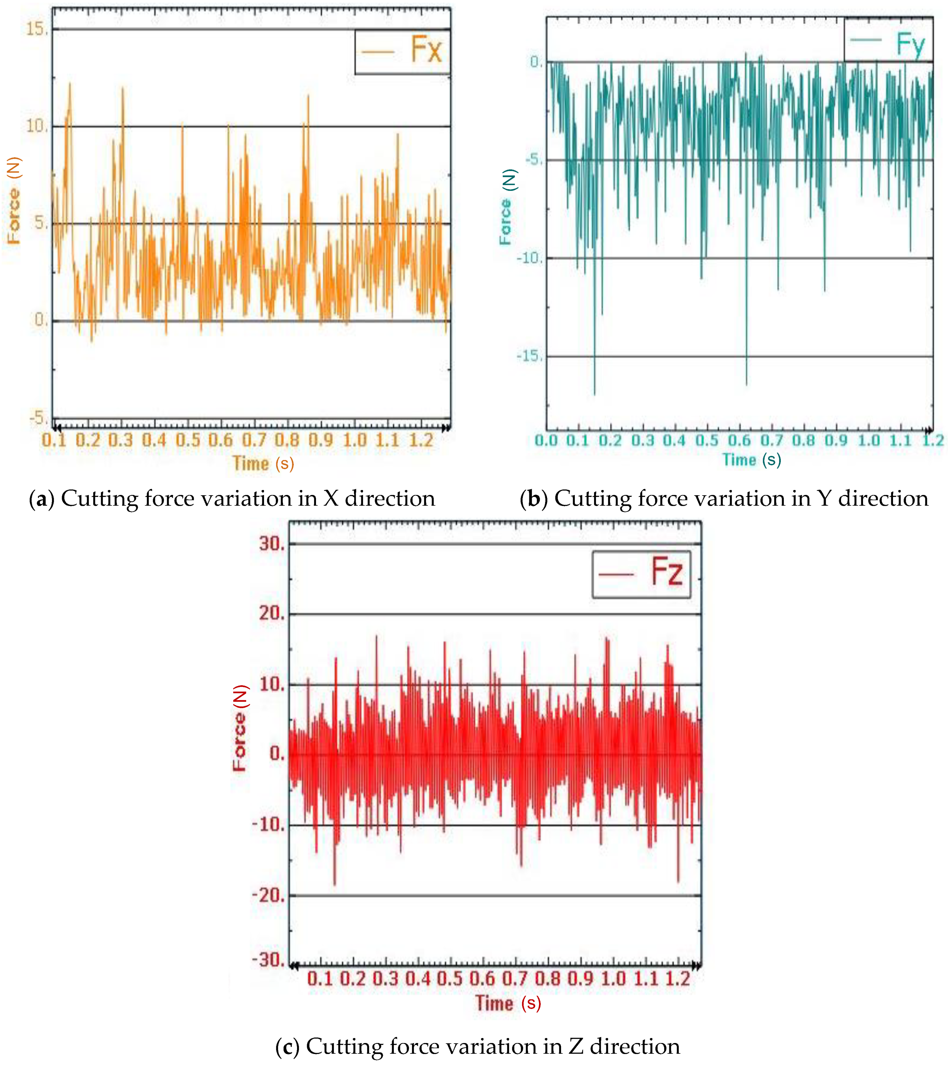
Figure 8 is a schematic diagram showing the cutting force variation curve. Where the spindle speed is 1500 r/min, the cutting depth ap = 5 mm, the cutting width aε = 10 mm, Feeding speed vf = 3000 mm/min, the vibration frequency is 20,000 Hz, the ultrasonic vibration-assisted amplitude A = 30 μm, and the simulation acquisition frequency is 600 Hz. It can also be seen from figure that during the cutting process, the maximum and minimum values of the cutting force in three directions fluctuate greatly. On one hand, the reason is that the Nomex honeycomb core is not a completely homogeneous structure. When the tool is processed to the honeycomb hole At the time, the required cutting force is small, and when the tool is processed to the bonding point of the honeycomb hole wall, the required cutting force is large. The other reason is that due to the frictional resistance of the upper and lower surfaces of the disc-cutter and the honeycomb core, the cutting direction of the cutter is different from the direction of the reaction force of the honeycomb core in the feed direction, so that each cutting The conditions for chip removal are also different at all times.
3.2. Verification of Ultrasonic Vibration-Assisted Cutting Simulation Model
In order to verify the accuracy of the finite element model, the simulation scheme in Table 3 was used to conduct cutting experiments on honeycomb-core materials, and the simulation resulted of cutting force were compared with the experimental results.
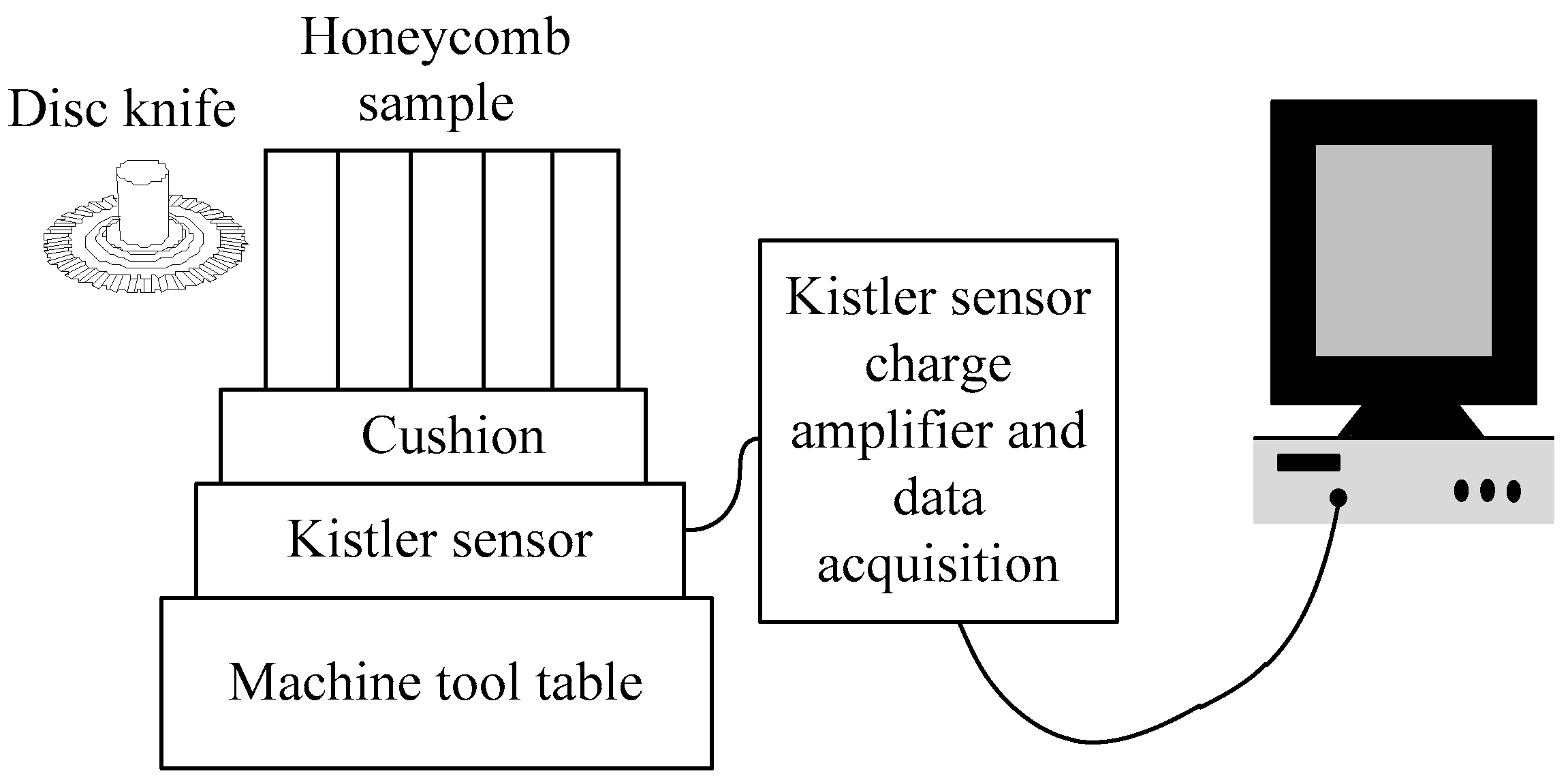
The ultrasonic vibration cutting experiment of the Nomex honeycomb-core composite material was carried out on the advanced ultrasonic processing machine US-50 produced by the Austrian GFM company. The measurement of the cutting force in the experiment was performed by the Kistler9257B dynamic force measurement system. In the test, the data acquisition frequency was 4000 Hz, the Nomex honeycomb-core material used in the test was NRH-3–48, and the sample size was 100 mm × 80 mm × 60 mm.
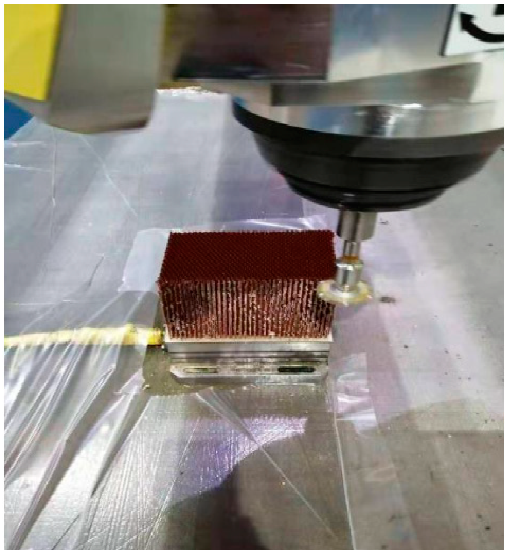
The cutting force measurement principle is shown in Figure 9. The basic principle is that the voltage analog signal of the cutting force in three directions is first measured by the Kistler9275B three-way dynamometer, and then the signal is collected by the quasi-static charge amplifier, data acquisition card and chassis. Then, it is converted into numeric signals by data-acquisition virtual instrument software for data storage and analysis by the computer, and finally the average value of the collected cutting force signals is used as the cutting force during the processing. During the experiment, each group of process parameters are tested twice, and the average value is taken to ensure the reliability of the experimental data. The specific processing environment is shown in Figure 10.
During the experiment, the spindle speed was 1500 r/min and the feed rate was 4500 mm/min. There were 8 groups of experiments, 4 groups of cutting width experiments and 4 groups of cutting depth experiments.
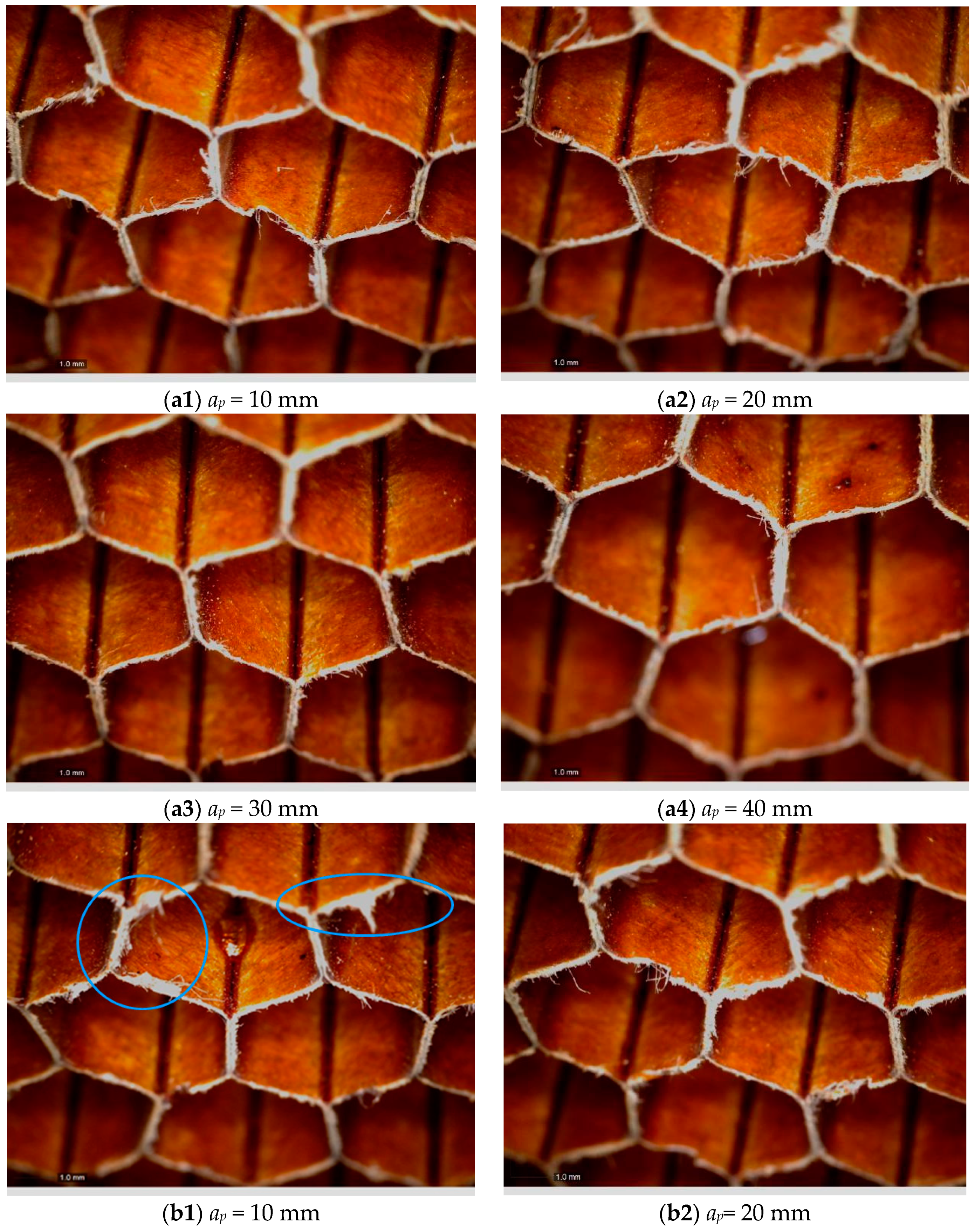
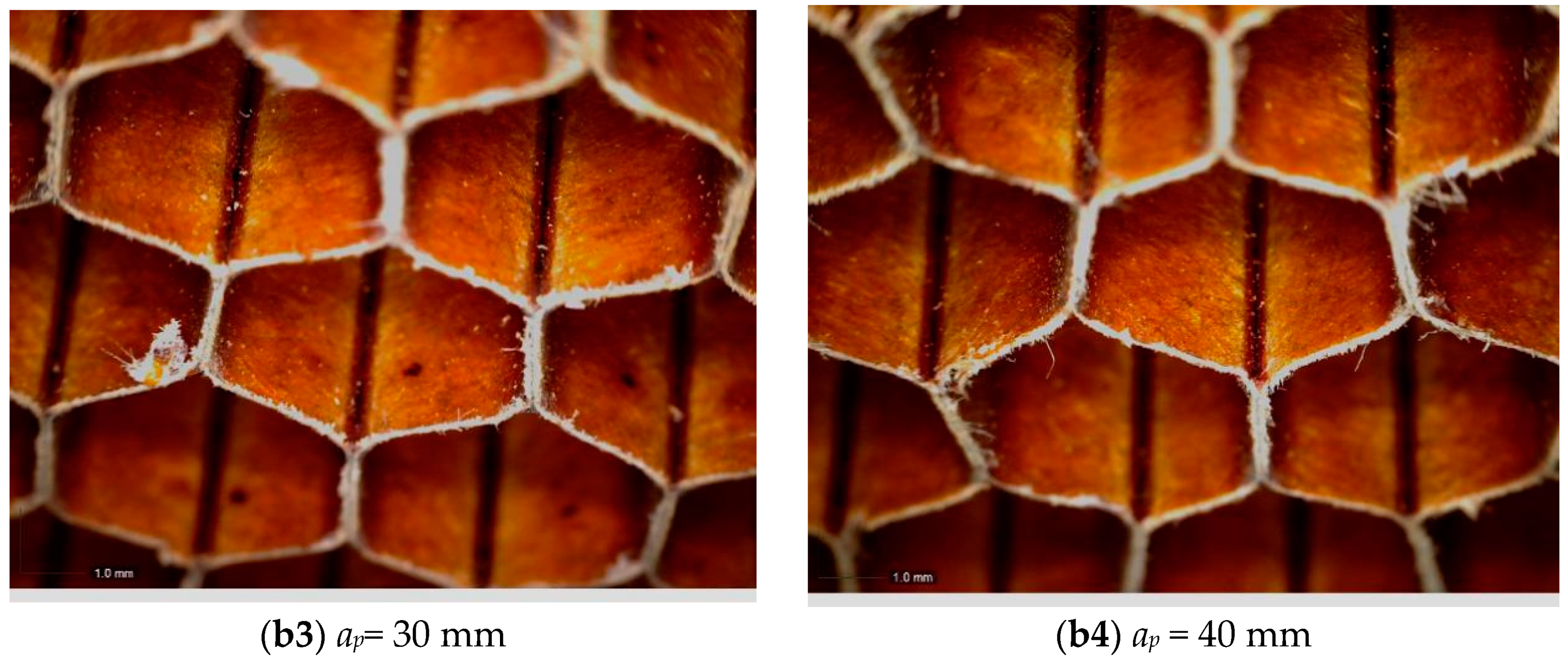
As shown in Figure 11, the surface topography of ae = 5 mm was obviously better than that of ae = 10 mm. There were a large number of burrs on the surface when the constant was 10 mm, in addition to a large number of burrs; the regular hexagon on the surface also had serious distortion. It could be seen, with the increase of cutting depth ap, the surface morphology of honey comb core material became better. When ap = 40 mm the surface of the material had almost no burrs, and the surface hexagon was regular.
Based on the change curve of the cutting force under different machining parameters obtained by actual cutting experiments, the simulation data of the vibration cutting of the disc-cutter was compared and analyzed. The experimental data were obtained by the three-dimensional dynamometer. The simulation data were obtained by the reaction force of the tool reference point in the ABAQUS software.
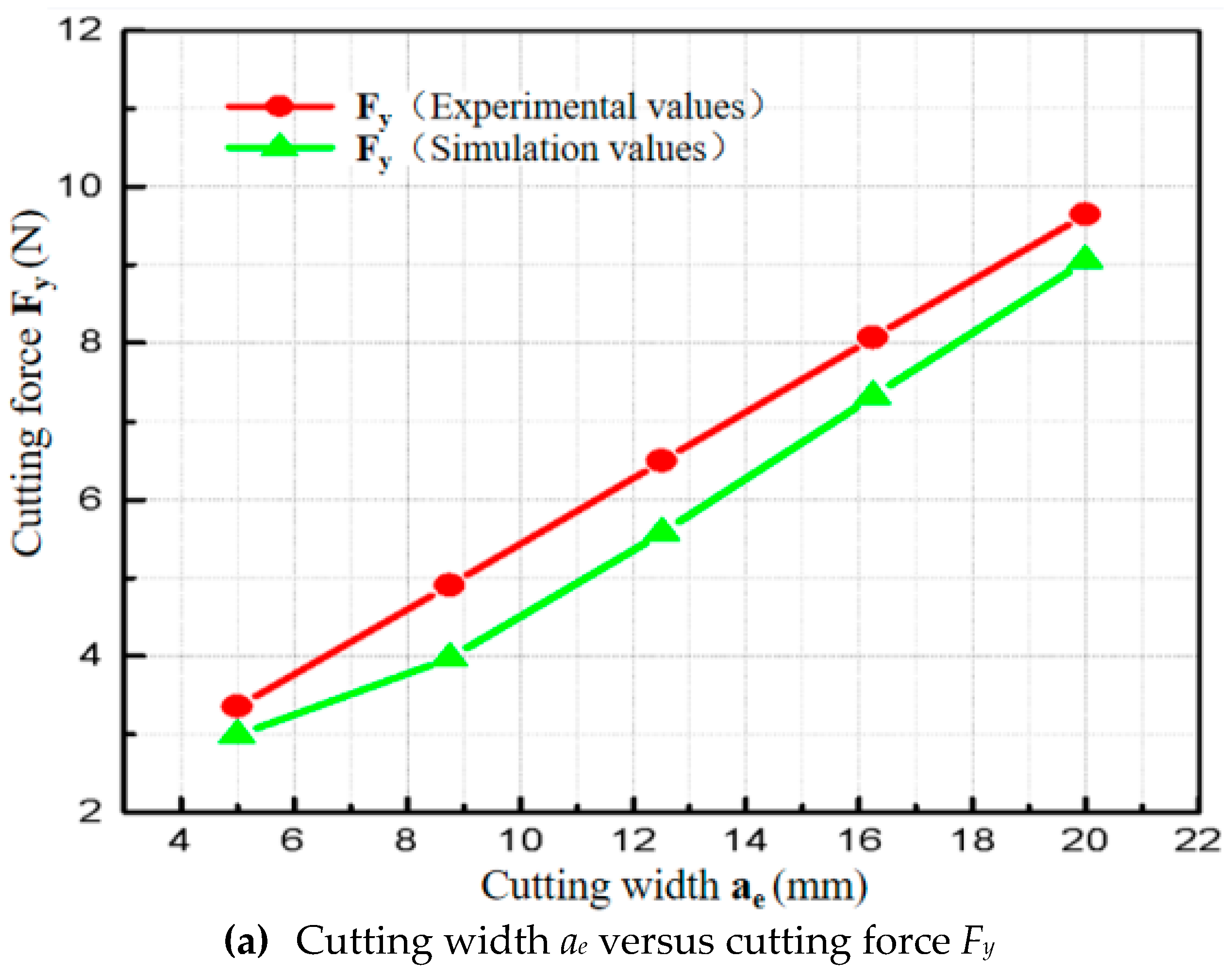
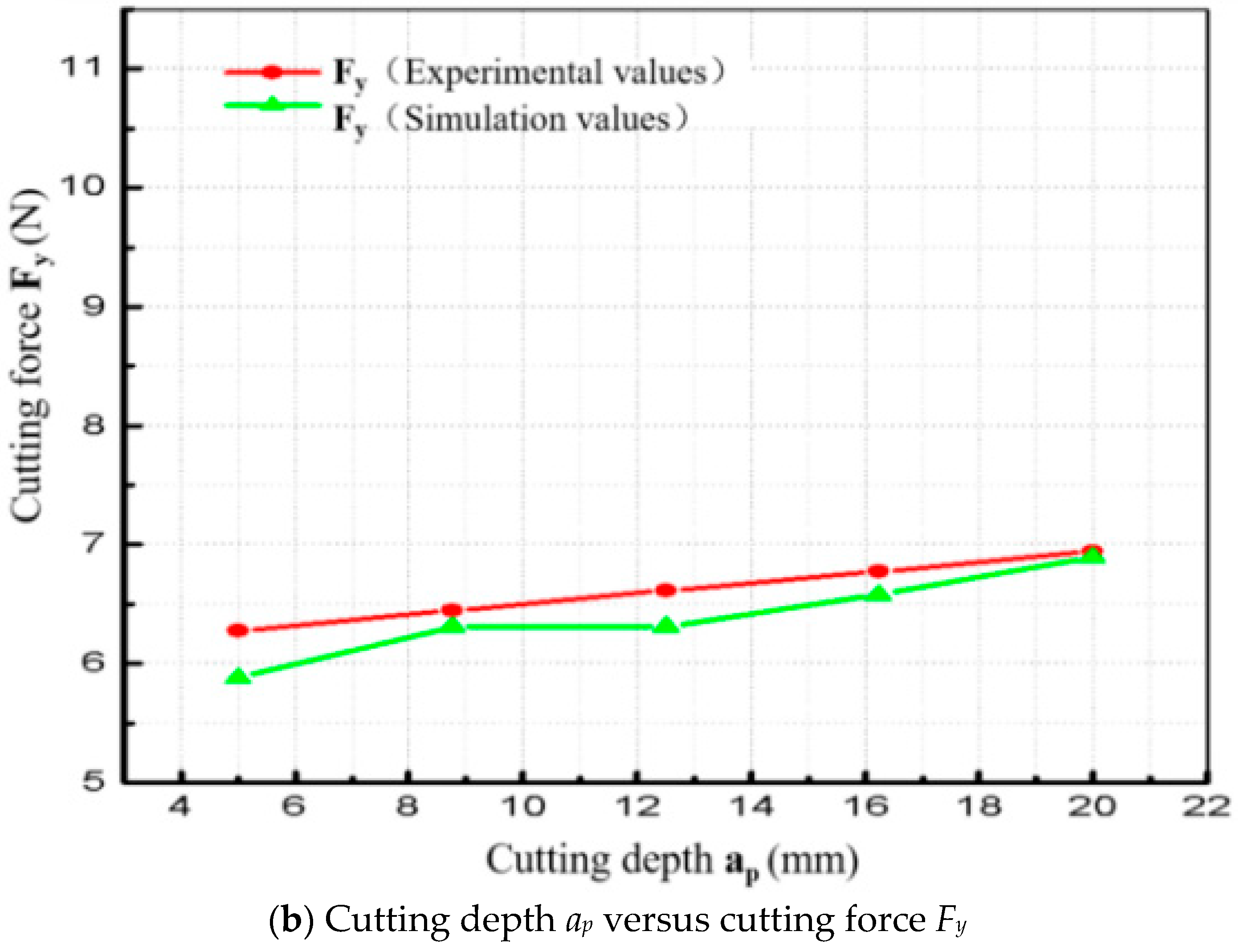
In the verification data, two sets of cutting data were selected, as shown in Figure 12. Among them, under the conditions of feed speed vf = 4000 mm/min, cutting depth ap = 10 mm, spindle speed n = 1500 r/min and amplitude μ = 30 μm, Figure 12a shows the cutting width ae versus cutting force Fy With the increase of the cutting width, the experimental value of the rotary-vibration-cutting force component of the disc-cutter increased linearly. This was mainly because the increase of the cutting width will increase the contact area between the tool and the workpiece surface. Thus, the cutting force increased. Under the conditions of feed speed vf = 4000 mm/min, cutting depth ae = 10 mm, spindle speed n = 1500 r/min and amplitude μ = 30 μm, Figure 12b showed the effect of cutting depth ap on cutting force Fy The regular curve, with the increase of the cutting depth, the cutting force tends to increase, but the increase of the entire cutting force was also gentler. Because the disc-cutter did not made the contact area between the tool and the workpiece surface increase during the cutting process.
Comparing the experiment results with the simulation results, the error is less than 13.2%. It can be verified that the finite element model proposed in this paper is basically reasonable. The tool wear and the phenolic resin coating outside the Nomex honeycomb-core composite material are neglected in the simulation process. The simulation data are slightly smaller than the measured data, but the simulation results can be applied to the actual Nomex honeycomb-core composite disc-cutter rotary-vibration-cutting.
4. Construction of Cutting Force Prediction Model Based on Response Surface Method
Based on the verified simulation model of disc-cutter cutting, a three-dimensional cutting force prediction model of Nomex honeycomb-core material disc-cutter rotating vibration cutting was established by using the response surface method.
4.1. Design of Cutting Simulation Test Scheme
In this test, the center complex response surface method is adopted, the cutting depth ap, cutting width ae and feed speed vf are setting as independent variables and cutting forces Fx, Fy and Fz as response values. Each factor in the three-factor center composite design has 5 levels, namely±1 level, 0 level and±0.5 level. The coding and level of test factors are shown in Table 4.
The Nomex honeycomb core disc-cutter rotary-vibration-cutting simulation test scheme is shown in Table 5.
4.2. Output Cutting Simulation Results
4.3. Construction of Cutting Force Prediction Model
Based on the experimental design method and response value, combined with the analysis software Design–Expert, the regression analysis was used to analyze the data. When the regression equation was established, some items may have no significant effect on the response. In order to obtain an optimal regression equation, these items should be removed without affecting the accuracy of the equation. The following equations are quadratic regression models for the rotational vibration cutting of the Nomex honeycomb-core composite material with disc-cutter.
where ap is the cutting depth (mm), ae is the cutting width (mm) and vf is the feed rate (mm/min).
4.4. Variance Analysis
Table 7 is variance analysis of disc-cutter Nomex honeycomb composites ultrasonic vibration-assisted cutting force prediction model. As can be seen from the results of variance analysis, in the regression model of Fx and Fy, P < 0.0001 and in regression model of Fz, P = < 0.005, which indicating that the regression model established for Fx, Fy and Fz was extremely significant. The feed speed vf, cutting depth ap and cutting width ae had a great influence on the cutting force of rotary vibration of the disc-cutter. The lack of fit of Fx (P = 0.7098 > 0.05), the lack of fit of Fy (P = 0.1271 > 0.05) and the lack of fit of Fz (P = 0.0767 > 0.05), indicating that the lack of fit of regression models of Fx, Fy and Fz was not significant. According to the credibility analysis of the quadratic regression equation, the coefficient of determination of the regression model of Fx was R2 = 0.9510 and the adjustment of R2 = 0.9069, indicating that the model could explain 90.69% of the experimental data; the coefficient of determination of the regression model of Fy was R2 = 0.9568, adjust R2 = 0.9179, indicating that the model could explain 91.79% of the experimental data; Fz regression model decision coefficient R2 = 0.8916, adjust R2 = 0.7940, indicating that the model could explain 79.40% of the experimental data.
Combining the above analysis of variance and model significance tests, it is shown that the predicted values of Fx, Fy and Fz fit well with the experimental values; the regression effect of the model was great, and it had a high credibility. Therefore, the regression model of the disc-cutter rotary-vibration-cutting force of the honeycomb-core material established by the response surface method was effective, and it could be used to analyze and predict the cutting force.
5. Conclusions
In order to improve the processing quality such as surface burrs and cutting damage caused by the cutting force during rotary-vibration-cutting honeycomb-core material, several key technologies involved in finite element simulation of honeycomb-core material model were studied in this paper, following conclusions could be obtained:
- (1)
- The three-dimensional finite element simulation model of disc-cutter which used in honeycomb-core material ultrasonic vibration-assisted cutting process was established, the material properties and material failure criteria were studied in detail;
- (2)
- The validation experiment was executed in order to verify the simulation resulted, the relative error between simulation results and experimental results was less than 13.2%;
- (3)
- The cutting force prediction model was established though the regression analysis based on the simulation results. According to the cutting force model, the influence of cutting parameters on cutting force could be predicted; the processing quality and the processing efficiency could be improved due to cutting parameters regulation;
- (4)
- By analyzing the influence of cutting parameters on the cutting force, it was concluded that larger cutting depth and smaller cutting width had better cutting performance which was reflected in less burrs and better surface integrity.
Author Contributions
Conceptualization, writing—original draft, W.C.; funding acquisition, writing—review & editing, J.Z.; supervision, Y.C. All authors have read and agreed to the published version of the manuscript.
Funding
This work was supported by the Science and Technology Planning Project of Shenzhen Municipality (JCYJ20180306170733170), National Science and Technology Major Project of the Ministry of Science and Technology of China (2018ZX04002-001).
Conflicts of Interest
The authors declare no conflicts of interest.
References
- Zuhri, M.Y.M.; Guan, Z.W.; Cantwell, W.J. The mechanical properties of natural fibre based honeycomb core materials. Compos. Part B 2014, 58, 1–9. [Google Scholar] [CrossRef]
- Gomet, L.; Marguet, S.; Marckmann, G. Modeling of Nomex honeycomb cores, linear and nonlinear behavior. Mech. Adv. Mater. Struc. 2007, 14, 589–601. [Google Scholar]
- Castaniea, B.; Bouveta, C.; Aminand, Y. Modelling of low-energy low-velocity impact on Nomex honeycomb sandwich structures with metallic skins. Int. J. Impact Eng. 2008, 35, 620–634. [Google Scholar] [CrossRef] [Green Version]
- Alix, S.; Marais, S.; Morvan, C.; Lebrun, L. Biocomposite materials from flax plants: Preparation and properties. Compos. Part A 2008, 39, 1793–1801. [Google Scholar] [CrossRef]
- Tauhiduzzaman, M.; Carlsson, L.A. Influence of constraints on the effective inplane extensional properties of honeycomb core. Compos. Struct. 2019, 209, 616–624. [Google Scholar] [CrossRef]
- Rinker, M.; Ratcliffe, J.G.; Adams, D.O.; Krueger, R. Characterizing Facesheet/Core Disbanding in Honeycomb Core Sandwich Structure; NASA/CR-2013-217959, NIA Report No. 2013-0115; NASA: Washington, DC, USA, 2013; pp. 1–35. [Google Scholar]
- Malek, S.; Gibson, L. Effective elastic properties of periodic hexagonal honeycombs. Mech. Mater. 2015, 91, 226–240. [Google Scholar] [CrossRef]
- Hohe, J. A direct homogenisation approach for determination of the stiffness matrix for micro heterogeneous plates with application to sandwich panels. Compos. B Eng. 2003, 34, 615–626. [Google Scholar] [CrossRef]
- Sun, G.Y.; Zhang, J.T.; Li, S.Q.; Fang, J.G.; Wang, E.D.; Li, Q. Dynamic response of sandwich panel with hierarchical honeycomb cores subject to blast loading. Thin Wall. Struct. 2019, 142, 499–515. [Google Scholar] [CrossRef]
- Karpat, Y.; Bahtiyar, O.; Deger, B. Mechanistic force modeling for milling of unidirectional carbon fiber reinforced polymer laminates. Int. J. Mach. Tool. Manuf. 2012, 56, 79–93. [Google Scholar] [CrossRef]
- Roy, R.; Park, S.J.; Kweon, J.H.; Choi, J.H. Characterization of Nomex honeycomb core constituent material mechanical properties. Compos. Struct. 2014, 117, 255–266. [Google Scholar] [CrossRef]
- Heimbs, S.; Pein, M. Failure behaviour of honeycomb sandwich corner joints and inserts. Compos. Struct. 2009, 89, 575–588. [Google Scholar] [CrossRef]
- Aminanda, Y.; Castanie, B.; Barrau, J.J.; Thevenet, P. Experimental analysis and modeling of the crushing of honeycomb cores. Appl. Compos. Mater. 2005, 12, 213–227. [Google Scholar] [CrossRef]
- Potlkuri, R.; Rao, U.K. Determination of Elastic Properties of Reverted Hexagonal Honeycomb Core: FEM Approach. Mater. Today Proc. 2017, 4, 8645–8653. [Google Scholar] [CrossRef]
- Hu, X.P.; Yu, B.H.; Li, X.Y.; Chen, N.C. Research on Cutting Force Model of Triangular Blade for Ultrasonic Assisted Cutting Honeycomb Composites. Procedia CIRP 2017, 66, 159–163. [Google Scholar] [CrossRef]
- Zhang, S.F.; Wang, J.F.; Ma, F.J.; Liu, Y.; Sha, Z.H. Simulation analysis of the effect of tool parameters on the cutting force and temperature of ultrasonic cutting honeycomb core. J. Dalian Jiaotong Univ. 2017, 38, 57–61. [Google Scholar]
- Jin, C.Z. Research on NOMEX Honeycomb Material High-Speed Processing Technology and Retention Reliability; Zhejiang University: Zhejiang, China, 2006. [Google Scholar]
Figure 1.
Disc-cutter geometry model.

Figure 2.
Nomex honeycomb-core composite geometry model.

Figure 3.
Nomex simulation model of ultrasonic vibration cutting of disk cutter.

Figure 4.
Schematic diagram of the rotary vibration amplitude loading of disc-cutter.

Figure 5.
Schematic diagram of ultrasonic vibration-assisted cutting of Nomex honeycomb-core composite material.
Figure 5.
Schematic diagram of ultrasonic vibration-assisted cutting of Nomex honeycomb-core composite material.

Figure 6.
Disc-cutter ultrasonic vibration-assisted cutting scheme.

Figure 7.
Rotary-vibration-cutting simulation of disc-cutter.

Figure 8.
Simulation of cutting force changing curve by rotating vibration of the disc-cutter.

Figure 9.
Cutting-force measurement principle.

Figure 10.
Overview of experimental devices.

Figure 11.
Honeycomb-core material topography. (a) Honeycomb-core material morphology (cutting width ae = 5 mm); (b) honeycomb-core material morphology (cutting width ae = 10 mm).
Figure 11.
Honeycomb-core material topography. (a) Honeycomb-core material morphology (cutting width ae = 5 mm); (b) honeycomb-core material morphology (cutting width ae = 10 mm).


Figure 12.
Simulation and test data verification.


Table 1.
Geometric parameters of disc-cutter.
| Features of the Model | Parameter |
|---|---|
| Cutter diameter | 50.8 mm |
| Angle of wedge | 14° |
| Height of tool | 5 mm |
| inner diameter of tool | 12 mm |
| Material | Density ρ (kg/m3) | Elastic Modulus E/Gpa | Poisson’s Ratio σ | Thermal Expansion Coefficient 10−6/°C | Thermal Conductivity W/(m·°C) | Specific Heat Capacity J/(kg·°C) |
|---|---|---|---|---|---|---|
| W18Cr4 V high speed steel | 7800 | 210 | 0.3 | 4.5 | 24 | 420 |
| Nomex honeycomb core | 1334 | 2.01 | 0.25 | 4 | 0.123 | 1300 |
Table 3.
Single factor simulation scheme for ultrasonic vibration-assisted cutting of disk cutter.
| Number | Cutting Width (mm) | Cutting Depth (mm) | Feed Speed (mm/min) |
|---|---|---|---|
| 1 | 5 | 5 | 3000 |
| 2 | 8.75 | 8.75 | 3750 |
| 3 | 12.5 | 12.5 | 4500 |
| 4 | 16.25 | 16.25 | 5250 |
| 5 | 20 | 20 | 6000 |
Table 4.
Test factors and encoding level.
| Factor | Encoding Level | ||||
|---|---|---|---|---|---|
| −1 | −0.5 | 0 | 0.5 | +1 | |
| ap (mm) | 5 | 8.75 | 12.5 | 16.25 | 20 |
| ae (mm) | 5 | 8.75 | 12.5 | 16.25 | 20 |
| vf (mm/min) | 3000 | 3750 | 4500 | 5250 | 6000 |
Table 5.
Scheme of cutting simulation center composite design.
| Sequence | Coded Values | Actual Values | ||||
|---|---|---|---|---|---|---|
| ap (mm) | ae (mm) | vf (mm/min) | ap (mm) | ae (mm) | vf (mm/min) | |
| 1 | 0.5 | 0.5 | −0.5 | 16.25 | 16.25 | 3750 |
| 2 | 0 | 0 | 0 | 12.5 | 12.5 | 4500 |
| 3 | 0 | 0 | 1 | 12.5 | 12.5 | 6000 |
| 4 | 0 | 0 | 0 | 12.5 | 12.5 | 4500 |
| 5 | −0.5 | 0.5 | −0.5 | 8.75 | 16.25 | 3750 |
| 6 | 0 | 0 | 0 | 12.5 | 12.5 | 4500 |
| 7 | −0.5 | −0.5 | 0.5 | 8.75 | 8.75 | 5250 |
| 8 | −1 | 0 | 0 | 5 | 12.5 | 4500 |
| 9 | 0 | 1 | 0 | 12.5 | 20 | 4500 |
| 10 | 0.5 | −0.5 | −0.5 | 16.25 | 8.75 | 3750 |
| 11 | 0 | 0 | 0 | 12.5 | 12.5 | 4500 |
| 12 | 0 | 0 | −1 | 12.5 | 12.5 | 3000 |
| 13 | 1 | 0 | 0 | 20 | 12.5 | 4500 |
| 14 | 0 | 0 | 0 | 12.5 | 12.5 | 4500 |
| 15 | 0.5 | −0.5 | 0.5 | 16.25 | 8.75 | 5250 |
| 16 | −0.5 | −0.5 | −0.5 | 8.75 | 8.75 | 3750 |
| 17 | 0 | −1 | 0 | 12.5 | 5 | 4500 |
| 18 | −0.5 | 0.5 | 0.5 | 8.75 | 16.25 | 5250 |
| 19 | 0.5 | 0.5 | 0.5 | 16.25 | 16.25 | 5250 |
| 20 | 0 | 0 | 0 | 12.5 | 12.5 | 4500 |
Table 6.
Test parameters and simulation results of cutting force.
| Sequence | Experimental Combination | Response Value | ||||
|---|---|---|---|---|---|---|
| ap (mm) | ae (mm) | vf (mm/min) | Fx (N) | Fy (N) | Fz (N) | |
| 1 | 16.25 | 16.25 | 3750 | 5 | 7.17 | 8.31 |
| 2 | 12.5 | 12.5 | 4500 | 4.56 | 6.49 | 7.34 |
| 3 | 12.5 | 12.5 | 6000 | 6.01 | 6.48 | 7.63 |
| 4 | 12.5 | 12.5 | 4500 | 5.9 | 6.87 | 8 |
| 5 | 8.75 | 16.25 | 3750 | 5.92 | 7.92 | 9.29 |
| 6 | 12.5 | 12.5 | 4500 | 5.9 | 6.56 | 7.67 |
| 7 | 8.75 | 8.75 | 5250 | 4.6 | 4.96 | 7.45 |
| 8 | 5 | 12.5 | 4500 | 4.53 | 6.03 | 9.03 |
| 9 | 12.5 | 20 | 4500 | 8.67 | 9.4 | 10.55 |
| 10 | 16.25 | 8.75 | 3750 | 5.1 | 5.21 | 6.25 |
| 11 | 12.5 | 12.5 | 4500 | 5.02 | 6.68 | 7.22 |
| 12 | 12.5 | 12.5 | 3000 | 4.21 | 5.74 | 6.59 |
| 13 | 20 | 12.5 | 4500 | 6.87 | 7.2 | 8 |
| 14 | 12.5 | 12.5 | 4500 | 6.01 | 6.5 | 7.74 |
| 15 | 16.25 | 8.75 | 5250 | 5.58 | 5.3 | 6.65 |
| 16 | 8.75 | 8.75 | 3750 | 3.95 | 4 | 5.65 |
| 17 | 12.5 | 5 | 4500 | 4.03 | 4.07 | 6.53 |
| 18 | 8.75 | 16.25 | 5250 | 7.36 | 9.65 | 11.32 |
| 19 | 16.25 | 16.25 | 5250 | 9.12 | 9.2 | 10.85 |
| 20 | 12.5 | 12.5 | 4500 | 6.1 | 6.6 | 7.84 |
Table 7.
Regression model analysis of variance.
| Sources of Variance | Sum of Squares | Degrees of Freedom | Mean Square | F | P (Prob > F) | |
|---|---|---|---|---|---|---|
| Fx | Model | 27.71 | 9 | 3.08 | 21.56 | <0.0001 |
| residual | 1.43 | 10 | 0.14 | |||
| Loss of quasi | 0.53 | 5 | 0.11 | 0.59 | 0.7098 | |
| Pure error | 0.90 | 5 | 0.18 | |||
| Sum | 29.14 | 19 | ||||
| R2 = 0.9510, After the adjustment: R2 = 0.9069 | ||||||
| Fy | Model | 37.66 | 9 | 4.18 | 24.61 | <0.0001 |
| residual | 1.7 | 10 | 0.17 | |||
| Loss of quasi | 1.27 | 5 | 0.25 | 2.99 | 0.1271 | |
| Pure error | 0.43 | 5 | 0.085 | |||
| Sum | 39.36 | 19 | ||||
| R2 = 0.9568, After the adjustment: R2 = 0.9179 | ||||||
| Fz | Model | 32.27 | 9 | 3.59 | 9.14 | 0.0009 |
| residual | 3.92 | 10 | 0.39 | |||
| Loss of quasi | 3.14 | 5 | 0.63 | 4.01 | 0.0767 | |
| Pure error | 0.78 | 5 | 0.16 | |||
| Sum | 36.19 | 19 | ||||
| R2 = 0.8916, After the adjustment: R2 = 0.7940 | ||||||
© 2020 by the authors. Licensee MDPI, Basel, Switzerland. This article is an open access article distributed under the terms and conditions of the Creative Commons Attribution (CC BY) license (http://creativecommons.org/licenses/by/4.0/).
Share and Cite
MDPI and ACS Style
Cao, W.; Zha, J.; Chen, Y. Cutting Force Prediction and Experiment Verification of Paper Honeycomb Materials by Ultrasonic Vibration-Assisted Machining. Appl. Sci. 2020, 10, 4676. https://0-doi-org.brum.beds.ac.uk/10.3390/app10134676
AMA Style
Cao W, Zha J, Chen Y. Cutting Force Prediction and Experiment Verification of Paper Honeycomb Materials by Ultrasonic Vibration-Assisted Machining. Applied Sciences. 2020; 10(13):4676. https://0-doi-org.brum.beds.ac.uk/10.3390/app10134676
Chicago/Turabian StyleCao, Wenjun, Jun Zha, and Yaolong Chen. 2020. "Cutting Force Prediction and Experiment Verification of Paper Honeycomb Materials by Ultrasonic Vibration-Assisted Machining" Applied Sciences 10, no. 13: 4676. https://0-doi-org.brum.beds.ac.uk/10.3390/app10134676
Note that from the first issue of 2016, this journal uses article numbers instead of page numbers. See further details here.