Experimental Testing and Strut-and-Tie Modeling of Full-Scale Precast Concrete Girders with FRP Repaired End Regions

Department of Civil and Environmental Engineering, University of Illinois at Urbana-Champaign, 205 N. Mathews, Urbana, IL 61801, USA
*
Author to whom correspondence should be addressed.
Appl. Sci. 2020, 10(17), 5822; https://0-doi-org.brum.beds.ac.uk/10.3390/app10175822
Submission received: 27 July 2020
/
Revised: 18 August 2020
/
Accepted: 21 August 2020
/
Published: 22 August 2020
(This article belongs to the Special Issue Toward Sustainable Engineering Structures for Better Safety in Built-Environment)
Abstract
:Featured Application
FRP laminate, due to its high strength-to-weight ratio and the ease of application, could be utilized to efficiently restore the shear capacity of full-scale girders with distressed end regions under short shear span and to enhance their overall performance.
Abstract
Bridges located in cold regions are susceptible to extreme deterioration due to harsh climate conditions. Distressing of girder’s end regions is among the most common damage types in these bridges. This work focuses on addressing this type of damage through the use of a fiber reinforced polymer (FRP) repair scheme. Three-point-bending tests are conducted on the control, damaged, mortar repair and carbon fiber reinforced polymer (CFRP) repair cases of bridge girders that are taken out of service. Test results are analyzed to investigate the effectiveness of FRP to repair precast concrete (PC) girders with damaged end regions. Furthermore, since the damage is mainly localized at girder’s end region where beam theory is invalid, the behavior of FRP repaired end region (D-region) is studied using the strut-and-tie method. Based on the test results, a strut-and-tie model (STM) is proposed to estimate the shear capacity of the girder with the FRP repaired end region. The outcome of the experimental work shows that the FRP laminate repair system is effective in recovering and improving the shear behavior of the girder including both peak force and ductility. The proposed STM can be used to predict the shear capacity of the PC girder with a similar damage pattern to the one considered in this study.
1. Introduction
Among the most common structural deficiencies in bridges that jeopardizes the integrity and safety of precast concrete (PC) prestressed bridges is the damage of the PC girder’s end regions. This type of damage is typically in the form of cracking and spalling of concrete cover and corrosion of the steel reinforcement as shown in Figure 1a. One reason that contributes to this type of damage in PC prestressed girders is the failure of expansion joints allowing deicing material to leak through the joint onto the concrete girders, which causes the deterioration of concrete and corrosion of steel reinforcement. Steel corrosion eventually results in the cracking and spalling of concrete. Another reason that causes such damage is the freeze-thaw cycles that concrete bridges experience during their service life. Due to the localized nature of this type of deficiency, the damaged region only develops within a few feet from the end of the girder undermining the shear resistance of the girder.
As a quick fix for such a problem, mortar is commonly utilized to replace the damaged concrete and restore the original shape of the PC girder as shown in Figure 1b. However, the effectiveness of mortar repair to restore the shear capacity of the damaged end of a full-scale PC prestressed girder remains unknown. Recently, fiber reinforced polymer (FRP) composites have been widely used as repair material for damaged structures. Studies have shown that externally bonded FRP laminates could effectively repair and strengthen concrete bridge girders with shear deficiency [1,2,3,4,5,6,7].
Due to the nature of the distress mechanism, the damaged area is mostly concentrated at the end region. As a result, understanding the shear behavior of damaged PC prestressed beams under loads applied near the support (i.e., with small shear span-to-depth (a/d) ratio) is critical. Among all the published work, to the best of the author’s knowledge, only Shaw and Andrawes [8] and Ramseyer and Kang [9] focused on investigating the behavior of PC girders with damaged then repaired end regions under small a/d ratios. However, in Ramseyer and Kang’s study [9], the damage sustained by the specimens was load induced, which does not realistically represent the damage typically observed in the field due to deterioration. Further, Shaw and Andrawes [8] used in their study reduced-scale beam specimens and assumed that the damage is localized at the web only ignoring the impact of flange damage.
Due to the limited number of published studies related to this problem, there is still a need to understand experimentally the effectiveness of using FRP laminates in repairing the end regions of full-scale PC prestressed girders, especially under loads applied near the support (i.e., small a/d ratio). That said, to analyze the response of repaired beams analytically, and since the damage is localized at the end region of the beam, i.e., D-region, the use of the strut-and-tie model (STM) is warranted [10,11]. Many studies have shown the applications of STM to analyze the strengthening effect from FRP laminates [12,13,14,15,16,17,18]. However, STM has yet to be used to analyze the distressed end region of PC prestressed girder repaired by FRP laminate. This paper addresses the previously described knowledge gaps through: (1) performing tests on full-scale girders damaged then repaired using FRP laminates, and (2) develop and validate STM model for analyzing PC girders with damaged then FRP repaired end regions.
2. Girder Specimen Description
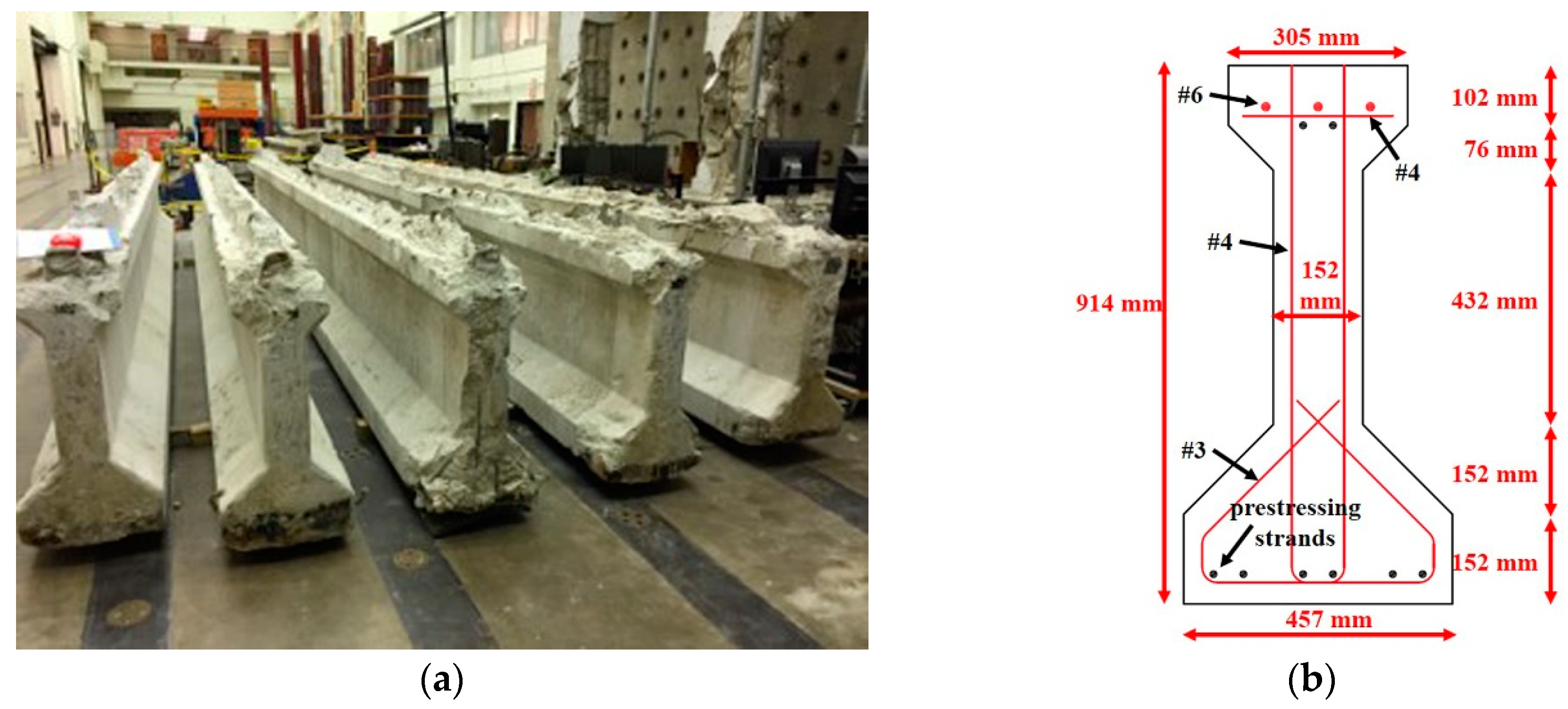
Five AASHTO Type II PC prestressed girders that were in service in the State of Illinois for over 40 years were extracted from a bridge and shipped to the lab at the University of Illinois at Urbana-Champaign as shown in Figure 2a. The girders have a length equal to 7.9 m. All the girders shared the same cross-section as depicted in Figure 2b.
Since the top of the girders was uneven, it was not feasible to apply the load directly on the girders top using an actuator. Therefore, to provide an even bearing area for the actuator, uneven concrete was removed from the top and a 304.8 mm × 304.8 mm × 101.6 mm block was cast using high strength mortar (Rapid Set Mortar Mix from CTS Cement, Inc.). According to the design plans, the girders were prestressed with six 12.7 mm diameter 7-wire stress relieved prestressing strands with an elastic modulus of 186.2 GPa and ultimate strength of 1862 MPa. The strands were pretensioned to 1303 MPa, approximately 70% of their ultimate strength. The mild steel used was Grade 40 with yield strength equal to 276 MPa. With a service life of over 40 years, the compressive strength of the concrete was unknown. Therefore, after one of the girders was tested, cylinders were drilled from the web of the girder and tested to obtain the compressive strength of the concrete. The average compressive strength of concrete was found to be 60.3 MPa.
3. Test Setup and Test Matrix
Three-point bending tests were performed on the ends of the girders to obtain the shear capacity of the girder. Due to the localized nature of end damage, a short shear span of 1.25 ( = 1.25) was selected to investigate the shear behavior of the girder. Given the depth to the centroid of the prestressing strands () is 863 mm, the distance from the center of the support to the center of loading plate was 1079 mm. The center-to-center distance of the girder supports was chosen as 6400 mm such that the other end of the girder was unaffected from the loading. The test setup is illustrated in Figure 3. An actuator with capacity of 1200 kN was used in the test. The vertical deflection of the girder was measured by placing a linear variable displacement transformer (LVDT) under the girder at the loading point. Three LVDTs installed on the web at 0°, 45° and 90° formed a rosette configuration to measure the averaged strain within web during loading and calculate the principal strain afterwards. Two strain gages were placed at top and bottom flanges to measure the compressive and tensile strain of concrete during loading. Figure 4 shows the instrumentation used in the test.
The test matrix is presented in Table 1. The testing included the control, damaged, mortar repaired and carbon fiber reinforced polymer (CFRP) repaired cases. The compressive strength of the mortar that was used in the repair process on the day of testing is also listed in the table.
4. Damage and Repair of Girder Ends
To induce realistic damage to the tested girders in pattern to that is sustained at the end regions of girders in service, the concrete cover was removed from the web and the bottom flange. For all the cases except the control case, concrete cover was removed to approximately the centerline of the stirrups. To remove the cover, a grid of holes was drilled first (Figure 5a) to control the depth of the concrete cover to be removed, and to weaken the concrete and ease the removal process. Next, a hammer drill with a chisel was utilized to remove the cover. A picture of the beam end after cover removal is depicted in Figure 5b.
After the cover was removed, the exposed surface was air blasted and vacuumed to provide a clean surface for the following mortar repair. It was essential to restore the shape of the damaged end before any other repair material such as FRP laminate was applied. Rapid mortar mix was used to obtain a fast repair. A trowel was used to place mortar layer on the concrete surface and to smooth the surface for following FRP laminate application. Due to its high Young’s modulus and ultimate strength, carbon FRP (CFRP) laminate was selected as the repairing material. The CFRP laminate was manufactured with unidirectional carbon fibers saturated in resin and had an elastic modulus of 86.9 GPa and tensile strength of 930 MPa. One layer of CFRP laminate had a thickness of 1.24 mm. Due to the blockage of the support bearing plate and the limited space under the girder near end region in the field, an externally bonded U-wrap scheme was not feasible. As a result, the 2-sided FRP repair approach was adopted, where FRP laminates were only applied at the girder sides and not the bottom side. After the mortar was set, FRP laminates with vertical fiber orientation were applied to the girder sides using the wet layup method. Figure 6 depicts a schematic and picture of the applied repair scheme. As illustrated in the figure, four panels of one layer of the FRP sheet with a width of 279 mm were applied starting from the center of the support bearing plate and spaced at 25.4 mm. Three longitudinal strips of CFRP laminate were placed atop the panels to serve as anchors to prevent the debonding of the vertical CFRP panels as shown in Figure 6a. Each strip was 1498 mm long and 76.2 mm wide. The longitudinal strips extended to 152.4 mm beyond the first and last panel. Vertical strain gage was attached to the third FRP panel to monitor the strain developed within the FRP laminate. Since the slip of strand was not anticipated, the strand slip of the control case was not monitored. After the strand slip was observed during the testing of the control girder, the slip of the strand during loading was monitored for the rest of the cases by attaching one LVDT to one of the prestressing strands.
5. Test Results
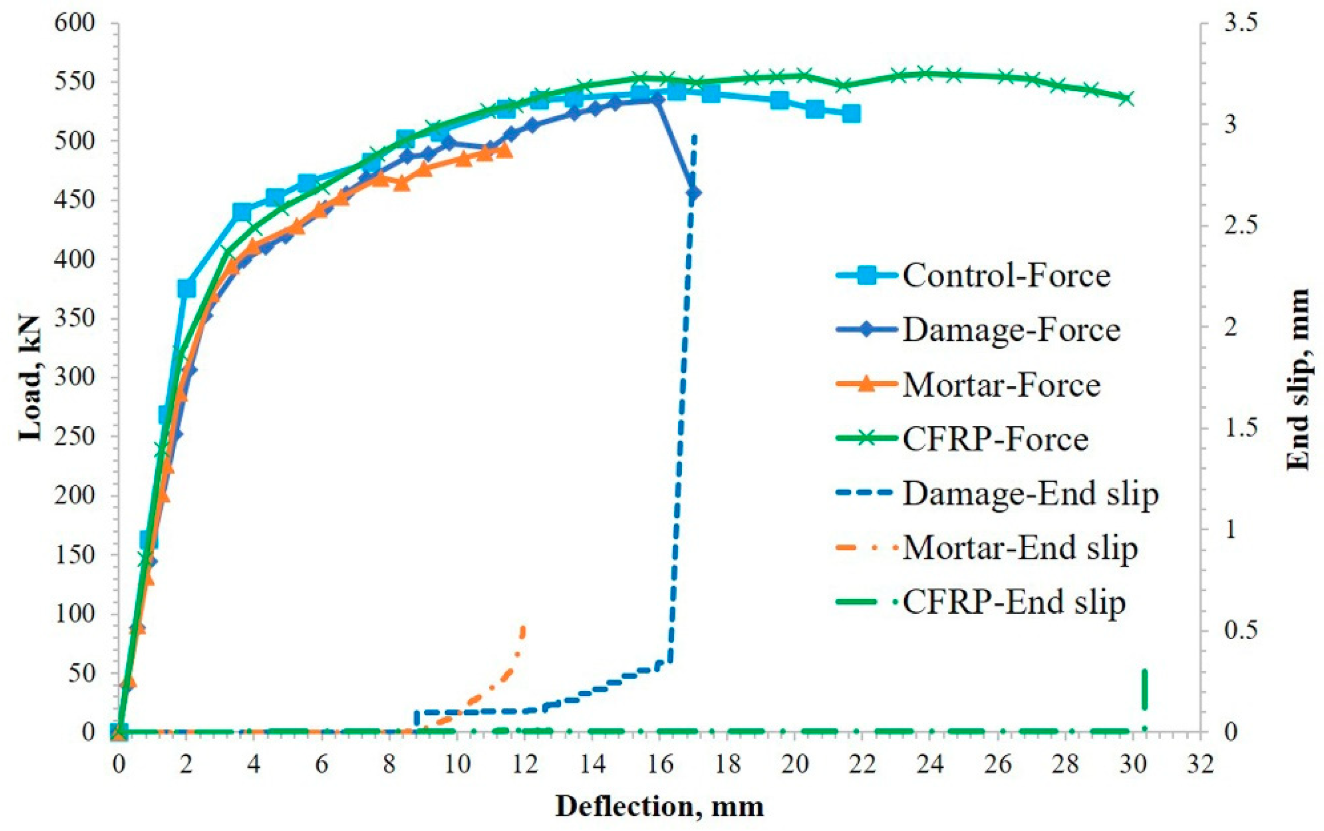
A summary of the four three-point flexural tests is presented in Table 2. The yielding point was selected as the point where the load vs. deflection curve showed significant nonlinearity. The ductility was defined as the ratio between ultimate deflection and deflection at yielding point. The load vs. deflection and strand slip vs. deflection curves were plotted in Figure 7. For the control, damaged and mortar repair cases, the girders failed in shear with a wide opening of inclined shear cracks and pullout of longitudinal strands combined with minor flexural cracks observed under the loading point. For the CFRP repair case, due to strong resistance in shear the girder showed more flexural cracks under the loading point than other cases. From the strand slip at the peak load, it is clearly noted that strands did not show a significant slip until the failure point, which indicated that strands slip had a minimal effect on the behavior of the girder.
6. Discussion on the Effect of Cover Damage and Mortar Repair
As shown in Figure 7, the removal of the concrete cover resulted in decreases of 14.4% and 22.2% in both initial stiffness and secant stiffness, respectively, as compared to the control case. However, the peak force only showed 1.2% reduction. This is mainly because the failure modes of the control and damaged cases (see Figure 8) were identical; both attributed to the pullout of the prestressing strands. Moreover, in the damaged specimen, the remaining core concrete was able to resist the compression diagonal strut force, despite the cover removal, without showing any signs of crushing. This was primarily attributed to the high concrete compressive strength. Nevertheless, the removal of the concrete cover showed a more detrimental effect on the stiffness and ductility than on peak load. The ductility of the damaged girder was reduced by 39.3% as compared to the control case.
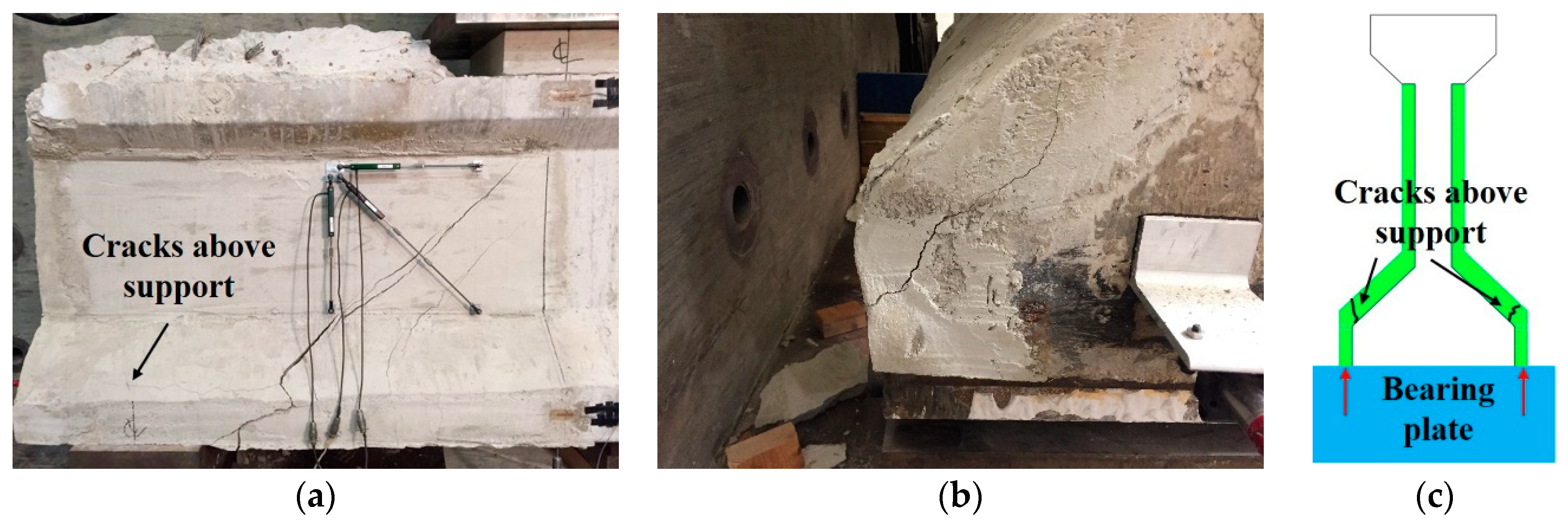
From the load vs. deflection curves, it can be seen that the mortar repair case nearly coincided with the damaged case. Compared to the control case, the mortar repaired case showed a reduction of 8.6%, 15.3% and 20.0% in the peak load, initial stiffness and secant stiffness at the yielding point, respectively. The ductility of mortar repair case was even worse than the damaged case with 53.5% reduction compared to the control case. Based on the test results, it seemed that the mortar repair alone failed to restore the shear capacity and ductility of the girder. There are several reasons that might have contributed to such unexpected behavior. First, the bond between the mortar mix and base concrete was not strong enough to allow stress transferred to mortar. Therefore, unlike the control and damaged cases, the mortar repair case only showed one main shear crack as shown in Figure 9a. Second, the strength and stiffness of the mortar layer was low compared to the base concrete and the mortar was not prestressed as the base concrete. Third, cracks within the mortar above the bearing plate were observed on both sides of the girder as shown in Figure 9b. This was due to the inability of the mortar to resist the vertical reaction as shown in Figure 9c. Such cracks impacted the integrity of the mortar cover and limited its participation in resisting shear stress. To prevent such cracks from developing, it is recommended that mortar repair should be terminated slightly above the bearing plate to prevent any contact with the bearing plate.
7. Discussion on the Effect of CFRP Laminate Repair
From Figure 7, it is observed that the overall behavior of the damaged girder was improved with CFRP laminate repair. Both peak load and ductility exceeded the control case with an increase of 2.6% and 9.6%, respectively. In addition, the CFRP laminate repair was able to recover most of the initial stiffness (only 2.3% less than the control case). This is mainly because the FRP laminate facilitated for the mortar to get engaged in the shear behavior during the early loading stage, which was not possible with the absence of the FRP laminate in the mortar repair case. Overall debonding of FRP panels was not observed during the test with only partial debonding concentrated around the second and third panel. This confirmed that the longitudinal anchorage strips were effective in providing sufficient anchorage for vertical FRP panels.
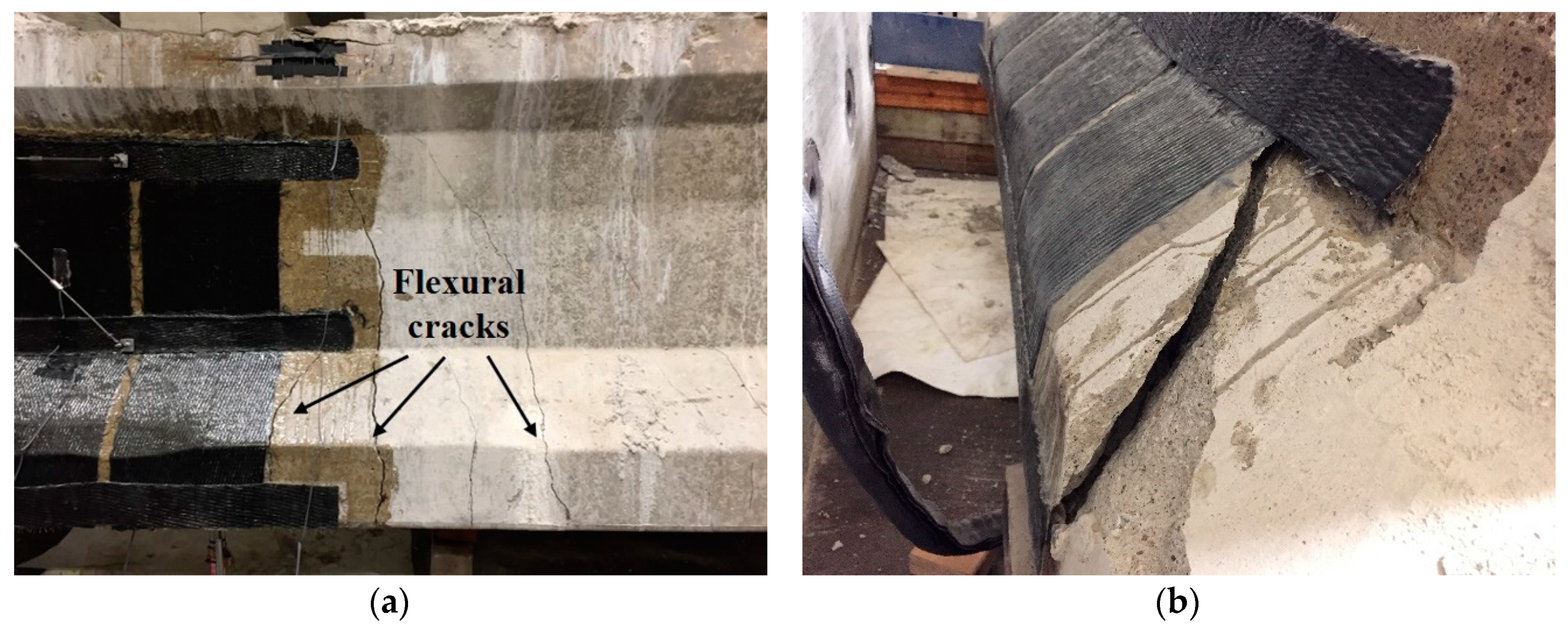
The failure mode of the CFRP repaired case differed from that of the other cases exhibiting more flexural cracks under the loading point as shown in Figure 10a. No significant shear cracks were observed on either side of the girder. The shift of the failure mode from shear to flexure indicates the effectiveness of the CFPR laminates in strengthening the damaged end of the girder increasing its shear capacity.
Figure 10b shows a large crack developed on the left side of the girder above the bearing plate, which was caused by the same mechanism illustrated in Figure 9c. However, based on the load vs. deflection curve, the initial stiffness was mostly recovered as well as the ductility of the girder. This indicates that due to the adhesion between the FRP laminate and mortar, the cracking of the mortar cover was kept under control.
8. Strut-and-Tie Model Development
The localized nature of the end damage of PC girder makes the conventional beam theory invalid for the calculation of shear capacity. Hence the strut-and-tie model (STM) was adopted in this study to estimate the shear capacity of the girder with a damaged end region repaired with FRP laminates. Figure 11 shows illustration of the proposed STM, which includes the following components: diagonal compression strut, nodal zone, horizontal tension tie and vertical tension tie. Due to limited work pertinent to the repair of end region damage of concrete girder with short shear span, only the test results of full-scale girder from this study and the test data from Shaw and Andrawes [8] who explored the effect of FRP laminate repairing the damaged end region of small-scale concrete beam were used to validate the proposed STM. The overall shear strength of the girder is dependent on the capacity of each component in STM, which is explained in the following section.
8.1. Diagonal Compression Strut
The capacity of diagonal compression strut was determined using the following expression:
where
- = cross-sectional area of compression strut;
- = nominal strength of diagonal compression strut;
- = compressive strength of concrete;
- = factor that accounts for the effective compressive strength of concrete.
8.2. Nodal Zone
The capacity of nodal zone was determined using Equation (2) [11].
where
- = cross-sectional area of the nodal zone face that is perpendicular to the reaction force;
- = nominal strength of the nodal zone;
- = factor that accounts for the effective compressive strength of concrete within the nodal zone.
The effective compressive strength of a nodal zone is dependent on whether the nodal zone is bounded by a compression force (C) or tension force (T) [11]. It is noted that in the three-point bending tests of both a small- and full-scale PC girder the nodal zones including the concrete above the bearing plate and under the loading point did not exhibit any damage. Hence for these cases did not govern the shear capacity.
8.3. Horizontal Tension Tie
For the prestressed girder, the horizontal tension tie represents the longitudinal prestressing strands, where the contribution of longitudinal mild steel reinforcement to the shear resistance is ignored. The capacity of horizontal tension tie was calculated as:
where
- = cross-sectional area of a single prestressing strand;
- = nominal strength of horizontal tension tie;
- = averaged maximum stress within prestressing strands;
- = effective prestressing stress within prestressing strands;
- = number of prestressing strands.
From Shaw and Andrawes [8] observations, the prestressing strands did not show a significant slip during the loading of small-scale PC beams. As a result, it was assumed that the maximum stress within strands was taken as the yielding stress, which was 1689 MPa and the effective prestress was taken as 1000 MPa. As for the full-scale PC girder tested in this study, the strands showed a negligible slip during loading and were pulled out right at the failure point of the girder. The study by Jiang [24] revealed that the required pull-out force to activate the free-end slip of strand is close to the jacking force. Therefore, the pull-out stress, was selected in this study as the jacking stress, 1275 MPa. To account for the girder’s 40 years of service, a relatively low value of 897 MPa was chosen as the effective prestress .
8.4. Vertical Tension Tie
Lastly, the capacity of vertical tension tie includes the contribution from three parts, namely, tensile strength of web concrete, yield strength of stirrups and strength of FRP laminate. Since mortar repair did not recover the shear capacity of both small- and full-scale beam, it is conservative to ignore the contribution from mortar. Equation (4) is proposed to calculate the capacity of the vertical tension tie.
where
- = total cross-sectional area of vertical stirrups crossing the inclined shear crack;
- = Young’s modulus of the FRP laminate;
- = nominal strength of vertical tension tie;
- = width of girder’s web;
- = tensile strength of concrete;
- = yielding strength of vertical stirrups;
- = projection of inclined crack along the longitudinal direction of the girder;
- = width of FRP laminate crossed by the inclined shear crack;
- = thickness of one FRP laminate;
- = effective strain of FRP laminate;
- = reduction factor that accounts for the bond between the mortar layer and base concrete.
To calculate the effective strain of the FRP laminate, the method proposed by ACI 440.2R [25] was adopted. Following Equations (5)–(8) illustrate the process to obtain .
where
- = active bond length of FRP laminates;
- = effective depth of the FRP laminate;
- = modification factor applied to account for concrete strength;
- = modification factor applied to account for wrapping scheme;
- = modulus ratio of elasticity between FRP and concrete.
It is worth noting that the reduction factor, was introduced to adjust the effectiveness of FRP repair based on the type of damage and the quality of the bond between mortar and base concrete. In this study, the factor was determined through the calibration process using the test results of the CFRP repaired small-scale PC beam [8] and full-scale PC girder tests.
Eventually, the shear capacity from STM is determined using the following equation:
where
- = shear capacity from STM;
- = inclination angle between diagonal strut and longitudinal direction.
8.5. Comparison and Discussion of Experimental and STM Results
The shear capacities of both small-scale and full-scale PC beams from as-built, damaged, mortar repaired and CFRP repaired cases were calculated using the proposed strut-and-tie model. The results are summarized in Table 3. From the table, it is noted that in general STM yielded close results showing a difference within 11% as compared to experimental results. For small-scale beams, the shear capacities of the control and damaged case from STM were 5% lower than those from test, whilst the mortar repair case from STM showed only 4% higher than the experimental test in peak force. However, the results from STM were 11% lower and 10% higher than those from tests for control and damaged cases, respectively in full-scale girder testing. Such differences were attributed to the uncertainty of the material properties used in STM including the tensile strength of concrete and maximum and effective prestressing stress within strands. Such uncertainty of material properties resulted from the unknown loading history and deterioration the girders experienced within their service life.
The value of represented the effectiveness of CFRP applied to the damaged end region. For the small-scale beam, only the web concrete cover was removed, which allowed partial CFRP laminates bonded to the original concrete at the bottom flange. Such bonding to the original concrete enabled the FRP laminates to develop a higher strain during loading and to achieve the full potential with close to 1. However, in the case of full-scale girders where the concrete cover was removed from the web through the bottom flange and CFRP laminates were attached atop the applied mortar, the response of the FRP laminate entirely depended on the behavior of the applied mortar. Moreover, the crack observed in Figure 9b compromised the integrity of the mortar layer, therefore, the effectiveness of the CFRP laminate was diminished showing the value of only 0.26. Based on the different values of , it is clear that whether the repairs are performed on the web alone or both web and bottom flange would impact the effectiveness of FRP laminate in recovering the shear capacity. If only web requires repair, is not necessarily needed in STM to predict the shear capacity. However, should be considered in STM when both the web and bottom flange are repaired. More studies need to be conducted to determine a range of for different repair cases.
9. Summary and Conclusions
The end damage of bridge PC girders due to the deterioration of concrete material under the influence of deicing material and freeze–thaw cycles jeopardizes the shear resistance of the girders. Due to its high strength-to-weight ratio, FRP laminate has been utilized to repair structurally deficient bridges. The effectiveness of the FRP laminate to restore the shear capacity of the PC girder with the distressed end region under short shear span was explored in this study. Three-point bending tests were conducted on full-scale PC girders and results from the control, damaged, mortar repair and CFRP repair cases were compared. In addition, a strut-and-tie model was proposed to analyze and predict the shear capacity of the PC girder with the repaired end region using the FRP laminate. Based on the test results, the following conclusions could be drawn:
- A mortar repair alone is not sufficient to recover the shear strength and ductility of the girder with damaged end regions.
- Longitudinal FRP anchors proved to be effective in preventing the overall debonding of FPR laminates at the end regions.
- The CFRP shear reinforcement repair showed the effectiveness in improving the shear behavior of the girder with the damaged end region. Even under an a/d ratio of 1.25, CFRP laminates were able to recover both peak force and ductility of the girder with a 2.6% and 9.6% improvement, respectively.
- For PC girders with a similar damage pattern to that was considered in this study, the proposed STM could estimate with reasonable accuracy the shear capacity of the girders repaired with FRP laminates.
Author Contributions
Formal analysis, H.Z.; investigation, H.Z.; data curation, H.Z.; writing—original draft preparation, H.Z.; visualization, H.Z.; conceptualization, B.A.; investigation, B.A.; writing—review and editing, B.A.; supervision, B.A.; project administration, B.A. All authors have read and agreed to the published version of the manuscript.
Funding
The authors acknowledge the funding provided for this research from the Illinois Department of Transportation (IDOT) and Illinois Center for Transportation (ICT) under project No. R27-156.
Conflicts of Interest
The authors declare no conflict of interest.
Nomenclature
| cross-sectional area of nodal zone face that is perpendicular to the reaction force | |
| cross-sectional area of compression strut | |
| cross-sectional area of a single prestressing strand | |
| total cross-sectional area of vertical stirrups crossing the inclined shear crack | |
| Young’s modulus of FRP laminate | |
| nominal strength of horizontal tension tie | |
| nominal strength of nodal zone | |
| nominal strength of diagonal compression strut | |
| nominal strength of vertical tension tie | |
| active bond length of FRP laminates | |
| shear capacity from STM | |
| width of girder’s web | |
| effective depth of FRP laminate | |
| compressive strength of concrete | |
| averaged maximum stress within prestressing strands | |
| effective prestressing stress within prestressing strands | |
| tensile strength of concrete | |
| yielding strength of vertical stirrups | |
| projection of inclined crack along the longitudinal direction of girder | |
| width of FRP laminate crossed by the inclined shear crack | |
| modification factor applied to account for concrete strength | |
| modification factor applied to account for wrapping scheme | |
| number of prestressing strands | |
| modulus ratio of elasticity between FRP and concrete | |
| thickness of one FRP laminate | |
| factor that accounts for the effective compressive strength of concrete within nodal zone | |
| reduction factor that accounts for the bond between mortar layer and base concrete | |
| effective strain of FRP laminate | |
| inclination angle between diagonal strut and longitudinal direction | |
| factor that accounts for the effective compressive strength of concrete |
References
- Dong, J.; Wang, Q.; Guan, Z. Structural Behaviour of RC Beams with External Flexural and Flexural–Shear Strengthening by FRP Sheets. Compos. Part B Eng. 2013, 44, 604–612. [Google Scholar] [CrossRef]
- Baggio, D.; Soudki, K.; Noël, M. Strengthening of Shear Critical RC Beams with Various FRP Systems. Constr. Build. Mater. 2014, 66, 634–644. [Google Scholar] [CrossRef]
- Panigrahi, A.K.; Biswal, K.C.; Barik, M.R. Strengthening of Shear Deficient RC T-Beams with Externally Bonded GFRP Sheets. Constr. Build. Mater. 2014, 57, 81–91. [Google Scholar] [CrossRef]
- Chen, G.M.; Zhang, Z.; Li, Y.L.; Li, X.Q.; Zhou, C.Y. T-section RC Beams Shear-strengthened with Anchored CFRP U-strips. Compos. Struct. 2016, 144, 57–79. [Google Scholar] [CrossRef]
- Li, W.; Leung, C.K.Y. Effect of Shear Span-depth Ratio on Mechanical Performance of RC Beams Strengthened in Shear with U-wrapping FRP Strips. Compos. Struct. 2017, 117, 141–157. [Google Scholar] [CrossRef]
- Belarbi, A.; Bae, S.; Ayoub, A.; Kuchma, D.; Mirmiran, A.; Okeil, A. Design of FRP Systems for Strengthening of Concrete Girders in Shear; National Cooperative Highway Research Program: Washington, DC, USA, 2011. [Google Scholar]
- Akroush, N.; Almahallawi, T.; Seif, M.; Sayed-Ahmed, E.Y. CFRP Shear Strengthening of Reinforced Concrete Beams in Zones of Combined Shear and Normal Stresses. Compos. Struct. 2017, 162, 47–53. [Google Scholar] [CrossRef]
- Shaw, I.; Andrawes, B. Repair of Damaged End Regions of PC Beams using Externally Bonded FRP Shear Reinforcement. Constr. Build. Mater. 2017, 148, 184–194. [Google Scholar] [CrossRef]
- Ramseyer, C.; Kang, T.H.K. Post-damage Repair of Prestressed Concrete Girders. Int. J. Concr. Struct. Mater. 2012, 6, 199–207. [Google Scholar] [CrossRef] [Green Version]
- American Association of State Highway and Transportation Officials. AASHTO LRFD Bridge Design Specifications; American Association of State Highway and Transportation Officials: Washington, DC, USA, 2017. [Google Scholar]
- ACI Committee 318. Building Code Requirements for Structural Concrete (ACI 318–19); ACI Committee: Farmington Hills, MI, USA, 2019. [Google Scholar]
- Tan, K.H.; Tong, K.; Tang, C.Y. Direct Strut-and-tie Model for Prestressed Deep Beams. J. Struct. Eng. 2001, 127, 1076–1084. [Google Scholar] [CrossRef]
- Park, S.; Aboutaha, R.S. Strut-and-tie Method for CFRP Strengthened Deep RC Members. J. Struct. Eng. 2009, 135, 632–643. [Google Scholar] [CrossRef]
- Godat, A.; Chaallal, O. Strut-and-tie Method for Externally Bonded FRP Shear-strengthened Large-scale RC Beams. Compos. Struct. 2013, 99, 327–338. [Google Scholar] [CrossRef]
- MacGregor, J.G. Derivation of Strut-and-tie Models for the 2002 ACI Code, ACI Publication, SP-208, Examples for the Design of Structural Concrete with Strut-and-Tie Models; ACI Committee: Farmington Hills, MI, USA, 2002. [Google Scholar]
- Reineck, K. Examples for the Design of Structural Concrete with Strut-and-tie Models, ACI Publication, SP-208; ACI Committee: Farmington Hills, MI, USA, 2002. [Google Scholar]
- Tjhin, T.N.; Kuchma, D.A. Computer-based Tools for Design by Strut-and-tie Method: Advances and Challenges. ACI Struct. J. 2002, 99, 586–594. [Google Scholar]
- Hanoon, A.N.; Jaafar, M.S.; Al Zaidee, S.R.; Hejazi, F.; Adb Aziz, F.N.A. Effectiveness Factor of the Strut-and-tie Model for Reinforced Concrete Deep Beams Strengthened with CFRP Sheet. J. Build. Eng. 2017, 12, 8–16. [Google Scholar] [CrossRef]
- Bergmeister, K.; Breen, J.E.; Jirsa, J.O.; Kreger, M.E. Detailing in Structural Concrete; Center for Transportation Research, University of Texas: Austin, TX, USA, 1993. [Google Scholar]
- MacGregor, J.G.; Wight, J.K. Reinforced Concrete: Mechanics and Design, 7th ed.; Prentice-Hall: Upper Saddle River, NJ, USA, 2004. [Google Scholar]
- Vecchio, F.J.; Collins, M.P. Compression Response of Cracked Reinforced Concrete. J. Struct. Eng. 1993, 119, 3590–3610. [Google Scholar] [CrossRef]
- Foster, S.J.; Gilbert, R.I. The Design of Nonflexural Members with Normal and High-strength Concretes. ACI Struct. J. 1996, 93, 3–10. [Google Scholar]
- Kaufmann, W.; Marti, P. Structural Concrete: Cracked Members Model. J. Struct. Eng. 1998, 124, 1467–1475. [Google Scholar] [CrossRef]
- Jiang, X. Bond Performance of High-capacity Strands in High Strength Concrete. Ph.D. Thesis, University of Tennessee, Knoxville, TN, USA, 2013. [Google Scholar]
- ACI Committee 440. Guide for the Design and Construction of Externally Bonded FRP Systems for Strengthening Concrete Structures (ACI 440.2R-08); ACI Committee: Farmington Hills, MI, USA, 2008. [Google Scholar]
Figure 1.
End region condition of precast concrete (PC) bridge girders: (a) end region damage and (b) mortar repair of girder end.
Figure 1.
End region condition of precast concrete (PC) bridge girders: (a) end region damage and (b) mortar repair of girder end.

Figure 2.
AASHTO Type II PC girders: (a) full-scale PC girder and (b) section details.

Figure 3.
Three-point bending testing.

Figure 4.
Three-point bending testing instrumentation (1:27).

Figure 5.
Concrete cover removal (1:27): (a) grid of drilled holes and (b) girder after cover removal.
Figure 5.
Concrete cover removal (1:27): (a) grid of drilled holes and (b) girder after cover removal.

Figure 6.
Carbon fiber reinforced polymer (CFRP) laminate repair design: (a) CFRP laminate dimensions and (b) CFRP test setup (1:27).
Figure 6.
Carbon fiber reinforced polymer (CFRP) laminate repair design: (a) CFRP laminate dimensions and (b) CFRP test setup (1:27).

Figure 7.
Load, end slip vs. deflection curves.

Figure 8.
Failure mode of control and damaged specimens (1:27): (a) control case after failure and (b) damage case after failure.
Figure 8.
Failure mode of control and damaged specimens (1:27): (a) control case after failure and (b) damage case after failure.

Figure 9.
Failure mode of the mortar repaired specimen: (a) mortar after failure (1:27); (b) cracks above bearing plate (1:10) and (c) cracks caused by uneven force transfer.
Figure 9.
Failure mode of the mortar repaired specimen: (a) mortar after failure (1:27); (b) cracks above bearing plate (1:10) and (c) cracks caused by uneven force transfer.

Figure 10.
Failure mode of the CFRP case: (a) flexural cracks under loading point (1:27) and (b) large cracking above bearing plate (1:10).
Figure 10.
Failure mode of the CFRP case: (a) flexural cracks under loading point (1:27) and (b) large cracking above bearing plate (1:10).

Figure 11.
Strut-and-tie model for fiber reinforced polymer (FRP) laminates repair.


Table 1.
Test matrix.
| Test | Cover Damage | Mortar Repair | FRP Repair | Concrete Compressive Strength, MPa | Mortar Compressive Strength, MPa |
|---|---|---|---|---|---|
| Control | n/a | n/a | n/a | 60.3 | n/a |
| Damaged | X | n/a | n/a | 60.3 | n/a |
| Mortar | X | X | n/a | n/a | 41.7 |
| CFRP | X | X | X | n/a | 54.1 |
Table 2.
Test results of full-scale PC girders.
| Specimen | Peak Load, kN | % of Control Peak Load | % of Control Initial Stiffness | % of Control Secant Stiffness at Yielding | % of Control Ductility | Strand Slip at Peak Load, mm | Max. FRP Strain, mm/mm |
|---|---|---|---|---|---|---|---|
| Control | 543.1 | 100.0 | 100.0 | 100.0 | 100.0 | n.d. | n.d. |
| Damage | 536.4 | 98.8 | 85.6 | 77.8 | 60.7 | 0.34 | n.d. |
| Mortar | 496.4 | 91.4 | 84.7 | 80.0 | 46.5 | 0.40 | n.d. |
| CFRP | 557.3 | 102.6 | 97.7 | 81.2 | 109.6 | 0.25 | 0.0011 |
Table 3.
Comparison of results between experiments and strut-and-tie model (STM).
| Tested Girder | Experiments | Strut-and-Tie Model | Comparison | ||
|---|---|---|---|---|---|
| Condition | , kN | , kN | |||
| Small-scale PC beam [8] | Control | 283 | n/a | 299 | 0.95 |
| Damaged | 206 | 218 | 0.95 | ||
| Mortar repair | 230 | 220 | 1.04 | ||
| CFRP repair | 338 | 0.96 | 338 | n/a | |
| Full-scale PC girder | Control | 543.1 | n/a | 609 | 0.89 |
| Damaged | 536.4 | 486 | 1.10 | ||
| Mortar repair | 496.4 | 486 | 1.02 | ||
| CFRP repair | 557.3 | 0.26 | 557 | n/a | |
© 2020 by the authors. Licensee MDPI, Basel, Switzerland. This article is an open access article distributed under the terms and conditions of the Creative Commons Attribution (CC BY) license (http://creativecommons.org/licenses/by/4.0/).
Share and Cite
MDPI and ACS Style
Zhao, H.; Andrawes, B. Experimental Testing and Strut-and-Tie Modeling of Full-Scale Precast Concrete Girders with FRP Repaired End Regions. Appl. Sci. 2020, 10, 5822. https://0-doi-org.brum.beds.ac.uk/10.3390/app10175822
AMA Style
Zhao H, Andrawes B. Experimental Testing and Strut-and-Tie Modeling of Full-Scale Precast Concrete Girders with FRP Repaired End Regions. Applied Sciences. 2020; 10(17):5822. https://0-doi-org.brum.beds.ac.uk/10.3390/app10175822
Chicago/Turabian StyleZhao, Hang, and Bassem Andrawes. 2020. "Experimental Testing and Strut-and-Tie Modeling of Full-Scale Precast Concrete Girders with FRP Repaired End Regions" Applied Sciences 10, no. 17: 5822. https://0-doi-org.brum.beds.ac.uk/10.3390/app10175822
Note that from the first issue of 2016, this journal uses article numbers instead of page numbers. See further details here.