Rock Breaking Performance of TBM Disc Cutter Assisted by High-Pressure Water Jet

1
School of Electrical & Power Engineering, China University of Mining and Technology, Xuzhou 221116, China
2
China Coal Technology Engineering Group Huaibei Blasting Technology Research Institute Limited Company, Huaibei 235099, China
*
Author to whom correspondence should be addressed.
Appl. Sci. 2020, 10(18), 6294; https://0-doi-org.brum.beds.ac.uk/10.3390/app10186294
Submission received: 24 July 2020
/
Revised: 4 September 2020
/
Accepted: 6 September 2020
/
Published: 10 September 2020
(This article belongs to the Section Mechanical Engineering)
Abstract
:Featured Application
Full-face hard rock tunnel drivage.
Abstract
A high-pressure water jet can break rock efficiently, which is of great potential to overcome the problems of a tunnel boring machine (TBM) in full-face hard rock tunnel digging, such as low digging efficiency and high disc cutter wear rate. Therefore, this paper presented a new tunneling method that is a TBM coupled with a high-pressure water jet. The rock failure mechanism under the coupled forces of a disc cutter and water jet was analyzed at first. Then, the finite element method (FEM) and smoothed particle hydrodynamics (SPH) method were used to establish a numerical model of rock broken by the disc cutter and water jet. Effects of parameters on rock breaking performance were studied based on the numerical model. Moreover, an experiment of the water jet cutting marble was carried out to verify the reliability of the numerical simulation. Results showed that the high-pressure water jet can increase the TBM digging efficiency and decrease the forces and wear rate of the disc cutter. The optimum nozzle diameter is 1.5 mm, while the optimum jet velocity is 224.5 m/s in this simulation. The results can provide theoretical guidance and data support for designing the most efficient system of a TBM with a water jet for digging a full-face hard rock tunnel.
1. Introduction
With the advantages of safe, reliable, and environmental preservation [1,2], the tunnel boring machine (TBM) has been increasingly used in long tunnels operations [3,4,5] and hydraulic pipelines construction [6,7]. However, it encounters a lot of problems in face of a full-face hard rock tunnel, such as low digging efficiency, high disc cutter wear rate, and the machine getting stuck [8,9]. Replacing the disc cutter implies more time and cost [10], which is also a problem for microtunneling boring machines (MTBM) [11,12]. Statistically, replacing and repairing TBM cutters in a high-abrasive stratum costs one-third of the total time of tunneling, while the cost of cutting tools is about one-third of the digging construction cost [13,14].
To reduce the TBM cutter wear and improve the tunneling efficiency, scholars have put forward many kinds of solutions. With a prediction model of disc cutter wear having been established, the working parameters of tunneling (penetration, diameter of the disc cutter, rotating speed of the cutter head, etc.) with the TBM have been optimized [15,16]. The arrangement form of the disc cutters on the cutter head has been improved based on the interaction mechanism between the rock and the disc cutter being revealed further [17,18]. According to analyzing the failure mechanism of the disc cutter, Lin [19] suggested to use new materials strengthened on the disc cutter to resist the rock wear. The wear rate of cutters has been monitored online to carry out the repair and maintenance of cutters and the cutter head in real time [20]. Although the above methods have achieved certain beneficial effects, the problems of the low digging efficiency and high disc cutter wear rate are still not solved.
Being of great potential in the field of rock crushing, the high-pressure water jet is gaining attention by scholars gradually. In tunneling excavation, efficiency and capacity analyses of an abrasive water jet (AWJ) were carried out, obtaining perfect working parameters (pressure, traverse speed, abrasive feed rate, and standoff distance) and an optimum operational cycle for AWJ cutting strategies [21,22,23]. The water jet has been used in oil and shale oil exploitation, increasing the perforation depth and enhancing the well production [24,25]. The water jet has been used to hydraulically slot coal rock for enhancing underground coal bed methane recovery and relieving the crustal stress of coal rock mass [26]. In geothermal exploitation, a new drilling technology, a mechanical driller assisted by a high-pressure water jet, has been developed for the challenging downhole environment [27]. The high-pressure water jet has been also used in underground mining, in which rock is broken by mechanical tools assisted with the water jet, reducing the cutting pick force and increasing the rock crushing efficiency [28,29,30,31].
According to the above literature review, the high-pressure water jet can break rock efficiently, which is of potential to overcome the problems of TBM in full-face hard rock tunnel digging. Therefore, this paper presented a new tunneling method that is a TBM coupled with a high-pressure water jet. The rock failure mechanism under the coupled forces of the disc cutter and water jet will be analyzed at first. Then, the finite element method (FEM) and smoothed particle hydrodynamics (SPH) method will be used to establish a numerical model of rock broken by the disc cutter and water jet to study the effect of parameters on the rock breaking performance. Finally, an experiment of the water jet cutting marble was carried out to verify the reliability of the numerical simulation. The results can provide theoretical guidance and data support for designing the most efficient system of a TBM with a water jet for digging a full-face hard rock tunnel.
2. New Method of Rock Broken by a TBM with a High-Pressure Water Jet
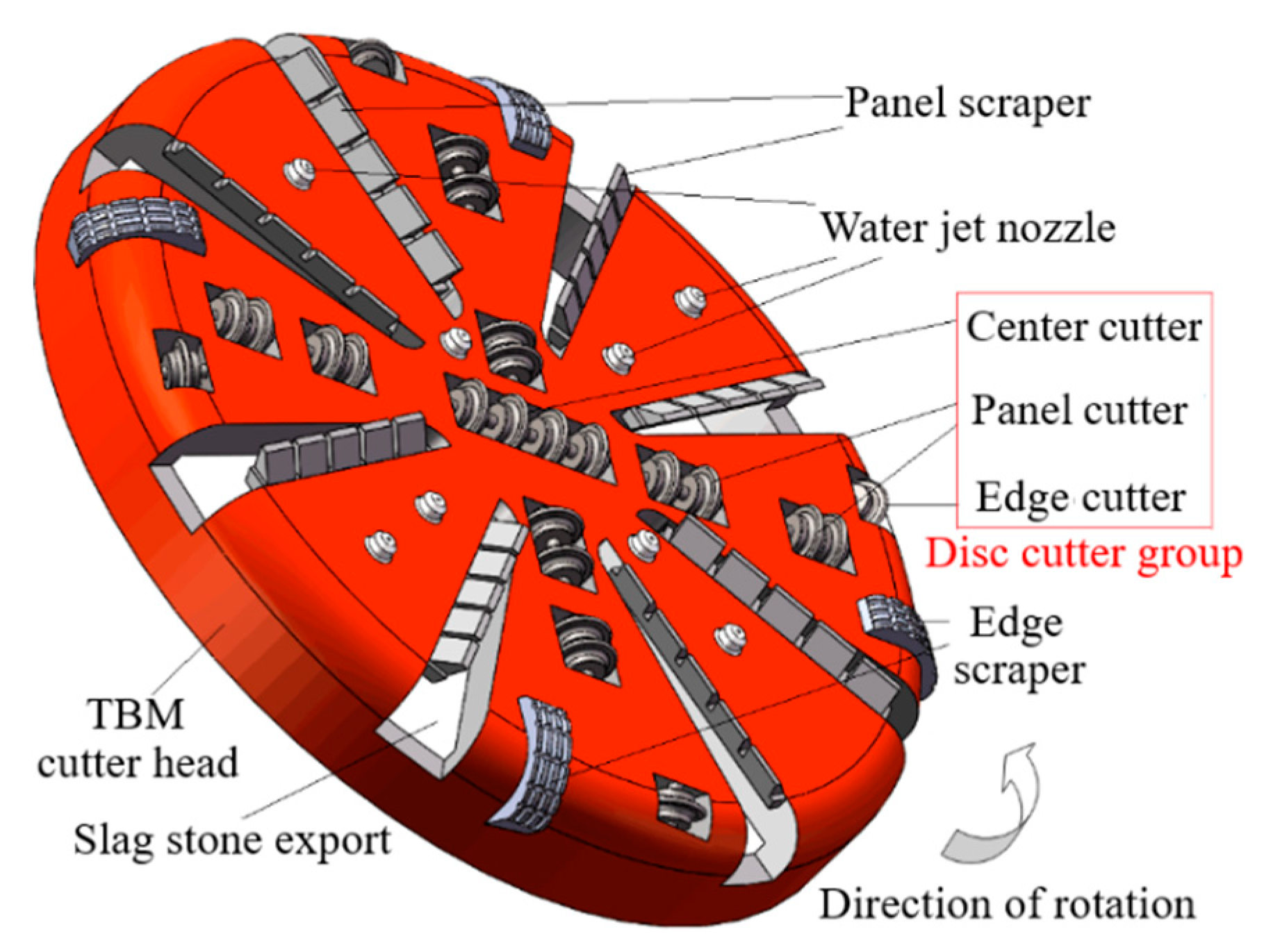
This paper presented a new method of rock breaking that is a TBM coupled with a high-pressure water jet. As shown in Figure 1, water jet nozzles are set up on the TBM cutter head, located at the front of the disc cutters and at the back of the scrapers. On the new cutter head, the disc cutter group (center cutter, panel cutter, and edge cutter) is still the main body for rock breaking, and both of the water jets and the scrapers play an auxiliary role. With the impacting of the water jet, a groove and numerous tiny cracks will appear on the dense rock mass, which can increase the degree of freedom for rock breaking. The scrapers can play a role of protecting the water jet nozzle to avoid hitting the slag stone broken by the front disc cutter. In the condition that there are few scrapers set on the TBM cutter head, it is necessary to equip a protecting component just like the scrapers.
Figure 2 shows the mechanism of rock broken by the disc cutter coupled with a high-pressure water jet. The rock breaking mechanism is different when the nozzle is located at the center section of the disc cutter or beside the center section of the disc cutter. As shown in Figure 2a, the groove on the rock mass formed by the impacting of the high-pressure water jet is at the center section of the disc cutter. Therefore, the disc cutter can easily roll and break the rock mass with the groove. Figure 2b shows that the groove is beside the center section of the disc cutter. Although there is no rock broken by the water jet on the rolling path of the disc cutter, the force loaded by the rock mass will decrease and the width of the crushing area will increase in the process of the rock being broken by the disc cutter rolling because the rock between the groove and disc cutter is located at the stress concentration area. With the degree of freedom provided by the grooving, this part of the rock mass will be broken by the thrust force of the disc cutter in the form of brittle cracking.
3. Setup for Numerical Simulation
The method of FEM coupled with SPH was used to simulate the process of rock breaking under the multiple forces of the TBM disc cutter and the high-pressure water jet. In the numerical simulation, the rock and disc cutter are set up based on FEM, while the water jet is built by SPH. Although FEM cannot reflect inherent cracks in the rock, it can clearly show the rock stress distribution during the process of rock breaking. Due to its advantage of being meshless, SPH can effectively solve the large deformation problem of the water jet.
3.1. Numerical Model
The rock is set as an explicit solid 3D element considering its deformation and failure criterion under the multiple forces of the TBM disc cutter and the high-pressure water jet. The linear equation of state is chosen to describe the properties of rock deformation, which can be expressed as Equation (1).
where Pr is the pressure within the rock, K is the rock bulk elastic modulus, ρr is the rock real density, and ρ0 is the reference density.
Failure plays a significant role in the process of rock being broken by the disc cutter and the water jet, which is determined by the maximum principal stress criterion. As shown in Equation (2), rock will be broken if the maximum principal stress exceeds the rock tensile strength, for rock is a brittle material whose tensile strength is rather less than the compression strength.
where σ1 (σ2) is the maximum principal stress, and σ is the rock tensile strength. The details of the rock physical properties are shown in Table 1.
The disc cutter is also set as an explicit solid 3D element but ignoring its deformation and failure criterion, for whom rigid is chosen as the material model. The details of the disc cutter physical properties are shown in Table 1.
The water jet is treated as a smooth particle flow, and the NULL material type was adopted to it with the Mie–Gruneisen equation of state, which can be expressed as the following [32].
where E0 is the internal energy per unit volume, μ is the volumetric strain, ρ0 is the initial density, γ0 is the Mie–Gruneisen constant, and α is the first order volume correction. C is the intercept of the Vs-Vp curve, while S1, S2, and S3 are the slope coefficients of the Vs-Vp curve. The above parameters of the jet fluid are shown in Table 2.
3.2. Geometrical Model Subsection
Based on the above modeling method, a geometrical model of rock broken by the disc cutter and the water jet has been established as shown in Figure 3. As the only part to touch and break the rock, a cutter ring was regarded as the disc cutter in this numerical simulation. The geometrical model of the disc cutter ring was built in accordance with the common 17 inches single-edge disc cutter, the outer ring diameter of which is 432 mm and the width of the disc cutter contacting the rock is 20 mm. A hexahedral mesh method was used for dividing the disc cutter geometrical model into 34,950 meshes. The geometry of the rock is a 100 × 80 × 40 mm cuboid, which is divided into 120,000 meshes. No constraints are set on the top surface of the rock, while the other surfaces are set as non-reflecting surfaces to simulate rock with an infinite volume. The water jet is set as a Φ1 × 5000 mm cylinder filling with 320 layers of SPH particles. In the enlarged view of Figure 3, the disc cutter is set to transparency, so that the geometry of the water jet can be seen clearly.
In practice, the water jet must be set at the front of the disc cutter, which is different from the position of the water jet relative to the disc cutter showed in Figure 3. Numerical simulation according to the actual situation will spend a lot of computation time. Therefore, to save the numerical resources, the position of the water jet is changed to go through the disc cutter, and the only setting that needs to be canceled in the numerical simulation is that of the contact between the water jet and disc cutter.
3.3. Evaluation Criteria and Variable Selection
The groove and tiny cracks created by the high-pressure water jet will increase the degree of freedom for rock breaking, which can reduce the forces and wear of the disc cutter and increase the rock breaking efficiency. This paper chooses disc cutter kinetic energy and rock crushing volume as the evaluation criteria to judge the performance of the water jet. In certain times, a smaller decrease in disc cutter kinetic energy represents smaller forces and wear of the disc cutter, while more rock crushing volume represents a higher rock breaking efficiency.
The velocity, diameter, and location of the water jet were chosen as the variables for obtaining the optimum parameters of the rock broken by the disc cutter coupled with the high-pressure water jet. The location of water jet is the distance between the center of the water jet and the center section of the disc cutter, which is shown by S in Figure 4. The details of the three variables are shown in Table 3.
The jet velocity and jet diameter are related to the energy of the water jet for rock breaking, which can be expressed as Equation (4). The jet velocity is chosen as the only variable to determine the energy of the water jet for rock breaking. The energy of the water jet for rock breaking per unit time must be constant when the jet diameter changes. As shown in Equation (4), the jet velocity is inversely proportional to the jet diameter. Therefore, the jet velocities (200/153/126/109/96 m/s) correspond to the jet diameters (1/1.5/2/2.5/3 mm), respectively.
where Et is the energy of the water jet for rock breaking per unit time, ρw is the density of the water jet, Q is the volume flow rate of the water jet, V is the jet velocity, and D is the jet diameter.
Parameters about the disc cutter were fixed as a constant in the numerical simulation. The initial linear velocity of the disc cutter is 52.3 mm/s, the initial angular velocity of the disc cutter is 0.24 rad/s, and the penetration of the disc cutter is 8 mm.
4. Results and Discussion
4.1. Mechanics of Rock Broken by the Disc Cutter Couple With a Water Jet
The mechanics of rock broken by the disc cutter coupled with a water jet were analyzed under the condition that the nozzle is located at the center section of the disc cutter firstly. There is a gap, approximately 0.012 μm, between the rock and the disc cutter at the initial time in the simulation. When the calculation time is less than 0.23 μs, the rock is contacted to the water jet only. Therefore, stress of the rock elements is formed by the impacting of the water jet as shown in the stress concentration area in Figure 5. According to the failure criterion, rock will be broken if the maximum principal stress exceeds the rock tensile strength, forming a groove in the rock mass by the impacting of the water jet finally.
When the calculation time exceeds 0.23 μs, the rock will be in contact with both the water jet and the disc cutter. Therefore, stress of the rock elements is formed by the water jet coupled with the disc cutter. As shown in Figure 5, the rock in area 1 is broken by the water jet, while the one in area 2 is broken by the disc cutter. Since the groove on the rock mass formed by the impacting of the water jet creates more degree of freedom for rock breaking, the disc cutter can roll and break the rock mass easily.
In Figure 5, three rock elements (A, B, and C), located in, near, and far from the traverse route of the water jet, respectively, were chosen to study the stress distribution and failure mechanism of the rock. Their maximum principle stress is shown in Figure 6. The rock element fails if its maximum principle stress surpasses 28.5 MPa. Rock element A will fail at 0.0033 s calculation time under the impacting of the water jet, rock element B will fail at 0.0071 s calculation time under the coupled force of the water jet and disc cutter, and rock element C will fail at 0.0125 s calculation time under the rolling force of the disc cutter.
Then, the mechanics of rock broken by the disc cutter couple with a water jet were analyzed under the condition that the nozzle is located beside the center section of the disc cutter. Figure 7 shows that the stress of the rock elements is formed by the water jet coupled with the disc cutter. Rock in area 1, on the moving path of the water jet, will be broken by the water jet, while rock in area 2, on the rolling path of the disc cutter, will be broken by the disc cutter. Rock in area 3, between the water jet and disc cutter, is in the shear stress concentration area, which will be broken by the thrust force of the disc cutter in the form of brittle cracking. The simulation results are consistent with the theoretical analysis results in Section 2 of this paper.
In Figure 7, another three rock elements (A, B, and C), located in the traverse route of the water jet, between the water jet and disc cutter, and in the rolling route of the disc cutter, were chosen to study the stress distribution and failure mechanism of the rock. Figure 8 shows their maximum principle stress. Rock element A will fail at 0.0085 s calculation time under the impacting of the water jet, while rock element B will fail at 0.0128 s calculation time under the rolling force of the disc cutter. Rock element C will not fail in all calculation times for its maximum principle stress did not exceed the rock tensile strength. However, it has become rock debris under the thrust force of the disc cutter.
4.2. Effect of Parameters on Rock Breaking Performance
As the first evaluation criterion to judge the performance of the water jet, the kinetic energy can reflect the forces and wear rate of the disc cutter. The initial kinetic energy of the disc cutter is set as a constant, which is related to its initial linear velocity and angular velocity set in the numerical simulation. Along with the calculation, the kinetic energy of the disc cutter will decrease for more and more energy will be used to break the rock mass. Therefore, a small decrease in the disc cutter kinetic energy represents the smaller forces and wear rate of the disc cutter at the same time.
To study the effect of the jet velocity on the disc cutter kinetic energy, the jet velocity is set as the single variable, while the jet location and diameter are constant (S = 0 mm, D = 1 mm). As shown in Figure 9, the water jet can slow down the kinetic energy consumption of the disc cutter no matter what the velocity value of the water jet is in the simulation, because the water jet with the smallest velocity (100 m/s) can break the rock to create a groove on the rock mass, which can increase the freedom degree of rock breaking and then decrease the force and wear rate of the disc cutter. Moreover, the disc cutter kinetic energy used for breaking the rock mass will decrease with the increase in the jet velocity, except where the velocity of the water jet is 245 m/s. The reason is that the depth of the groove will increase with the growth of the jet velocity, leading to more freedom degrees of rock breaking. When the velocity of the water jet is more than 224 m/s, the groove depth is larger than the penetration of the disc cutter (8 mm), and in the simulations, the width of the groove created by the water jet with 224 m/s velocity is a little larger than the one by the water jet with 245 m/s velocity. Therefore, the kinetic energy of the disc cutter with the 224 m/s water jet decreases a little more slowly than the one with the 245 m/s water jet.
To study the effect of the jet location on the disc cutter kinetic energy, the jet location is set as the single variable, while the jet velocity and diameter are constant (V = 200 m/s, D = 1 mm). As shown in Figure 10, the water jet can slow down the kinetic energy consumption of the disc cutter when it is located at the traverse route of the disc cutter, and the water jet has an effect on the disc cutter kinetic energy when it is located beside the traverse route of the disc cutter. Figure 10 also shows that the center section of the disc cutter is the optimum location for the water jet, in that the lowest kinetic energy of the disc cutter will be used for breaking the rock mass.
To study the effect of the jet diameter on the disc cutter kinetic energy, the jet diameter and jet velocity are set as the variables, while the jet location is constant (S = 0 mm), and values of the two variables are selected according to the rule that the energy of the water jet for rock breaking per unit time must be constant. As shown in Figure 11, the water jet can slow down the kinetic energy consumption of the disc cutter no matter what diameter is set for the water jet in the simulation, because the velocity of the water jet with the largest diameter is 96 m/s, which also can break the rock to create a groove on the rock mass. Moreover, the disc cutter kinetic energy used for breaking the rock mass will decrease at first and then increase with the growth of the jet diameter. With the kinetic energy of the disc cutter as the evaluation criterion, 1.5 mm is the optimum value of the nozzle diameter in this simulation.
The second evaluation criterion is the rock crushing volume that can reflect the rock breaking efficiency. More rock crushing volume represents higher rock breaking efficiency. As shown in Figure 12, the water jet can increase the rock crushing volume no matter what location, velocity, and diameter is set for the water jet in the simulation. Furthermore, the rock crushing volume increases with the jet velocity, while it will increase at first and then decrease with the growth of the jet location or the jet diameter. With the kinetic energy of the disc cutter as the evaluation criterion, 1.5 mm is the optimum value for the water jet in this simulation. When jet location S is set to 14 mm, the rock crushing volume is the largest in all of the simulations, which contains the volume of rock between the water jet and disc cutter broken by the thrust force of the disc cutter.
4.3. Experimental Verification
To verify the reliability of the numerical simulation, an experiment was carried out, in which hard marble was cut by the high-pressure water jet. The nozzle diameter used in experiment is 1 mm, the traverse speed is 52.3 mm/s, and the stand-off distance is 3 mm. Pressure (5/10/15/20/25/30 MPa) is the only variable, which corresponds to the jet velocity in the simulation (100/141/173/200/224/245 m/s). Cutting depth is set as the evaluation criterion. Figure 13 shows the comparison of the results of the experiment and simulation. The rock cutting depth in the simulation keeps in touch with the one in the experiment.
5. Conclusions
A new tunneling method was presented in this paper that is a TBM coupled with a high-pressure water jet. A numerical simulation based on the FEM and SPH method was carried out to study the effect of parameters on rock breaking performance, which was proved to be reliable by the rock breaking experiment. The results can provide theoretical guidance and data support for designing the most efficient system of a TBM with a water jet for digging a full-face hard rock tunnel. The details of the conclusions are shown as follows.
- (1)
- Results of the theoretical analysis and numerical simulation showed that the high-pressure water jet can increase the TBM digging efficiency and decrease the disc cutter wear rate.
- (2)
- With the growth of the jet velocity, the force and wear of the disc cutter will reduce, and the rock breaking efficiency will increase. The optimum jet velocity is 224.5 m/s in this simulation.
- (3)
- With the kinetic energy of the disc cutter and the rock crushing volume as the evaluation criteria, 1.5mm is the optimum value for the water jet in the simulations.
- (4)
- The water jet located at the center section of the disc cutter plays a major role in reducing the force and wear of the disc cutter, while the one located beside the center section of the disc cutter plays a major role in increasing the rock breaking efficiency.
Author Contributions
Conceptualization, F.W. and C.G.; methodology, F.W.; software, F.W.; validation, F.W., D.Z. and C.G.; formal analysis, X.Z.; investigation, N.X.; resources, F.W.; data curation, D.Z.; writing—original draft preparation, F.W.; writing—review and editing, C.G.; visualization, X.Z.; supervision, C.G.; project administration, C.G.; funding acquisition, F.W. All authors have read and agreed to the published version of the manuscript.
Funding
This research was funded by the Fundamental Research Funds for the Central Universities, grant number 2019QNA07.
Conflicts of Interest
The authors declare no conflict of interest.
References
- Jiang, M.; Yin, Z. Analysis of stress redistribution in soil and earth pressure on tunnel lining by discrete element method. Tunn. Undergr. Sp. Tech. 2012, 32, 251–259. [Google Scholar] [CrossRef]
- Wu, H.-N.; Shen, S.-L.; Yang, J. Identification of Tunnel Settlement Caused by Land Subsidence in Soft Deposit of Shanghai. J. Perform. Constr. Facil. 2017, 31, 04017092. [Google Scholar] [CrossRef] [Green Version]
- Sousa, J.A.E.; Negro, A.; Fernandes, M.M.; Cardoso, A.S. Three-Dimensional Nonlinear Analyses of a Metro Tunnel in São Paulo Porous Clay, Brazil. J. Geotech. Geoenviron. Eng. 2011, 137, 376–384. [Google Scholar] [CrossRef]
- Wu, H.-N.; Shen, S.-L.; Yang, J.; Zhou, A. Soil-tunnel interaction modelling for shield tunnels considering shearing dislocation in longitudinal joints. Tunn. Undergr. Space Technol. 2018, 78, 168–177. [Google Scholar] [CrossRef]
- Ren, D.-J.; Shen, S.-L.; Arulrajah, A.; Wu, H.-N. Evaluation of ground loss ratio with moving trajectories induced in double-O-tube (DOT) tunnelling. Can. Geotech. J. 2018, 55, 894–902. [Google Scholar] [CrossRef]
- Benato, A.; Oreste, P. Prediction of penetration per revolution in TBM tunneling as a function of intact rock and rock mass characteristics. Int. J. Rock Mech. Min. Sci. 2015, 74, 119–127. [Google Scholar] [CrossRef]
- Shen, S.-L.; Cui, Q.-L.; Ho, C.-E.; Xu, Y.-S. Ground Response to Multiple Parallel Microtunneling Operations in Cemented Silty Clay and Sand. J. Geotech. Geoenviron. Eng. 2016, 142, 04016001. [Google Scholar] [CrossRef]
- Farrokh, E.; Kim, D.Y. A discussion on hard rock TBM cutter wear and cutter head intervention interval length evaluation. Tunn. Undergr. Sp. Tech. 2018, 81, 336–357. [Google Scholar] [CrossRef]
- Zhang, X.; Lin, L.; Xia, Y.; Tan, Q.; Zhu, Z.; Mao, Q.; Zhou, M. Experimental study on wear of TBM disc cutter rings with different kinds of hardness. Tunn. Undergr. Space Technol. 2018, 82, 346–357. [Google Scholar] [CrossRef]
- Dai, W.; Xia, Y.; Ning, B.; Yang, M. Numerical Analysis of Stress and Temperature Fields in a Composite Stratum Based on a New Method of Shield Construction for Safety and Environmental Protection. Int. J. Environ. Res. Public Heal. 2020, 17, 530. [Google Scholar] [CrossRef] [Green Version]
- Hegab, M.Y.; Smith, G. Delay Time Analysis in Microtunneling Projects. J. Constr. Eng. Manag. 2007, 133, 191–195. [Google Scholar] [CrossRef]
- Gallo, J.; Pérez-Acebo, H. Performance model for Micro Tunnelling Boring Machines (MTBM). Informes de la Construcción 2018, 69, 546. [Google Scholar]
- Ren, D.-J.; Shen, S.-L.; Arulrajah, A.; Cheng, W.-C. Prediction Model of TBM Disc Cutter Wear During Tunnelling in Heterogeneous Ground. Rock Mech. Rock Eng. 2018, 51, 3599–3611. [Google Scholar] [CrossRef]
- Tan, Q.; Xie, L.; Xia, Y.; Zhu, Z.; Sun, X.; Wang, Y. Analysis of wear rate of TBM disc cutter. J. Cent. South Univ. 2015, 46, 843–848. [Google Scholar]
- Hassanpour, J. Development of an empirical model to estimate disc cutter wear for sedimentary and low to medium grade metamorphic rocks. Tunn. Undergr. Space Technol. 2018, 75, 90–99. [Google Scholar] [CrossRef]
- Tan, Q.; Sun, X.; Xia, Y.; Cai, X.; Zhu, Z.; Zhang, J. A wear prediction model of disc cutter for TBM. J. Cent. South Univ. 2017, 48, 54–60. [Google Scholar]
- Hassanpour, J.; Rostami, J.; Azali, S.T.; Zhao, J. Introduction of an empirical TBM cutter wear prediction model for pyroclastic and mafic igneous rocks; a case history of Karaj water conveyance tunnel, Iran. Tunn. Undergr. Space Technol. 2014, 43, 222–231. [Google Scholar] [CrossRef]
- Geng, Q. Analytical Research on the Wear Mechanism of TBM Disc Cutters Based on an Energy Approach. Chin. J. Mech. Eng. 2018, 54, 36. [Google Scholar] [CrossRef]
- Lin, L.; Xia, Y.; Mao, Q.; Zhang, X. Experimental Study on Wear Behaviors of TBM Disc Cutter Ring in Hard Rock Conditions. Tribol. Trans. 2018, 61, 1–10. [Google Scholar] [CrossRef]
- Huang, X.; Liu, Q.; Chen, L.; Pan, Y.; Liu, B.; Kang, Y.; Liu, X. Cutting force measurement and analyses of shell cutters on a mixshield tunnelling machine. Tunn. Undergr. Space Technol. 2018, 82, 325–345. [Google Scholar] [CrossRef]
- Oh, T.-M.; Cho, G.-C. Characterization of Effective Parameters in Abrasive Waterjet Rock Cutting. Rock Mech. Rock Eng. 2013, 47, 745–756. [Google Scholar] [CrossRef]
- Oh, T.-M.; Cho, G.-C. Rock Cutting Depth Model Based on Kinetic Energy of Abrasive Waterjet. Rock Mech. Rock Eng. 2015, 49, 1059–1072. [Google Scholar] [CrossRef]
- Pierri, L.C.; Dos Santos, R.P.; Junior, J.J.D.P.; Pains, A.M.; Noronha, M.A.M. High pressure abrasive water jet for excavation purpose: A tridimensional approach for cutting strategy. REM Int. Eng. J. 2019, 72, 25–30. [Google Scholar] [CrossRef] [Green Version]
- Huang, Z.; Li, G.; Shi, H.; Niu, J.; Song, X.; Shao, S. Abrasive water jet perforation experiments under ambient pressures. At. Sprays 2015, 25, 617–627. [Google Scholar] [CrossRef]
- Zhabin, A.; Polyakov, A.; Averin, E.; Khachaturian, W. Experimental studies on cutting oil shale by high-pressure water jets. Oil Shale 2019, 36, 32. [Google Scholar] [CrossRef]
- Liu, T.; Lin, B.; Yang, W.; Zou, Q.; Kong, J.; Yan, F. Cracking Process and Stress Field Evolution in Specimen Containing Combined Flaw Under Uniaxial Compression. Rock Mech. Rock Eng. 2016, 49, 3095–3113. [Google Scholar] [CrossRef]
- Stoxreiter, T.; Martin, A.; Teza, D.; Galler, R. Hard rock cutting with high pressure jets in various ambient pressure regimes. Int. J. Rock Mech. Min. Sci. 2018, 108, 179–188. [Google Scholar] [CrossRef]
- Ciccu, R.; Grosso, B. Improvement of Disc Cutter Performance by Water Jet Assistance. Rock Mech. Rock Eng. 2013, 47, 733–744. [Google Scholar] [CrossRef]
- Liu, S.; Chen, J.; Liu, X. Rock Breaking by Conical Pick Assisted with High Pressure Water Jet. Adv. Mech. Eng. 2014, 1–10. [Google Scholar]
- Liu, S.; Ji, H.; Han, N.; Guo, C. Experimental investigation and application on the cutting performance of cutting head for rock cutting assisted with multi-water jets. Int. J. Adv. Manuf. Technol. 2017, 94, 2715–2728. [Google Scholar] [CrossRef]
- Jiang, H.; Meng, D. Experimental Research on the Specific Energy Consumption of Rock Breakage Using Different Waterjet-Assisted Cutting Heads. Adv. Mater. Sci. Eng. 2018, 2018, 1–11. [Google Scholar] [CrossRef] [Green Version]
- Liu, X.; Liu, S.; Ji, H.; Huifu, J. Numerical research on rock breaking performance of water jet based on SPH. Powder Technol. 2015, 286, 181–192. [Google Scholar] [CrossRef]
Figure 1.
New tunnel boring machine (TBM) cutter head with a high-pressure water jet nozzle.

Figure 2.
Schematic diagram of rock being broken by a disc cutter coupled with a high-pressure water jet.
Figure 2.
Schematic diagram of rock being broken by a disc cutter coupled with a high-pressure water jet.

Figure 3.
Numerical model of a rock failure impacted by abrasive slurry jet (ASJ).

Figure 4.
Location of the water jet.

Figure 5.
Rock broken by the disc cutter assisted by a water jet.

Figure 6.
Maximum principle stress of the three rock elements.

Figure 7.
Rock stress formed by the disc cutter and water jet.

Figure 8.
Maximum principle stress of the three rock elements.

Figure 9.
Effect of velocity on the disc cutter kinetic energy.

Figure 10.
Effect of location on the disc cutter kinetic energy.

Figure 11.
Effect of diameter on the disc cutter kinetic energy.

Figure 12.
Effect of parameters on rock crushing volume.

Figure 13.
Comparison of the diagram of rock cutting depth in the experiment and simulation.


Table 1.
Material parameters of rock.
| Parts | ρ (kg/m3) | K (GPa) | Poisson Ratio | σ (MPa) |
|---|---|---|---|---|
| Rock | 2500 | 33.1 | 0.22 | 28.5 |
| Disc cutter | 9500 | 3200 | 0.3 | / |
Table 2.
Material parameters of the water jet.
| Parameters | ρ0 (kg/m3) | γ0 (m/s) | C | S1 | S2 | S3 | E0 | α |
|---|---|---|---|---|---|---|---|---|
| Value | 1000 | 0.35 | 1647 | 1.921 | −0.096 | 0 | 2.86 × 10⁻⁶ | 0 |
Table 3.
Values chosen for the variables.
| Parameters | Values |
|---|---|
| Jet velocity (m/s) | 100/141/173/200/224/245 |
| Jet diameter (mm) | 1/1.5/2/2.5/3 |
| Jet location (mm) | 0/10/12/14/16/18 |
© 2020 by the authors. Licensee MDPI, Basel, Switzerland. This article is an open access article distributed under the terms and conditions of the Creative Commons Attribution (CC BY) license (http://creativecommons.org/licenses/by/4.0/).
Share and Cite
MDPI and ACS Style
Wang, F.; Zhou, D.; Zhou, X.; Xiao, N.; Guo, C. Rock Breaking Performance of TBM Disc Cutter Assisted by High-Pressure Water Jet. Appl. Sci. 2020, 10, 6294. https://0-doi-org.brum.beds.ac.uk/10.3390/app10186294
AMA Style
Wang F, Zhou D, Zhou X, Xiao N, Guo C. Rock Breaking Performance of TBM Disc Cutter Assisted by High-Pressure Water Jet. Applied Sciences. 2020; 10(18):6294. https://0-doi-org.brum.beds.ac.uk/10.3390/app10186294
Chicago/Turabian StyleWang, Fengchao, Dapeng Zhou, Xin Zhou, Nanzhe Xiao, and Chuwen Guo. 2020. "Rock Breaking Performance of TBM Disc Cutter Assisted by High-Pressure Water Jet" Applied Sciences 10, no. 18: 6294. https://0-doi-org.brum.beds.ac.uk/10.3390/app10186294
Note that from the first issue of 2016, this journal uses article numbers instead of page numbers. See further details here.