Article

Bionic Design of a Potato Digging Shovel with Drag Reduction Based on the Discrete Element Method (DEM) in Clay Soil

1
College of Mechanical and Electrical Engineering, Shihezi University, Shihezi 832000, China
2
Key Laboratory of Bionic Engineering, Ministry of Education, Jilin University, Changchun 130022, China
*
Author to whom correspondence should be addressed.
Submission received: 28 July 2020 / Revised: 13 September 2020 / Accepted: 24 September 2020 / Published: 13 October 2020
(This article belongs to the Section Mechanical Engineering)

Abstract

:
The resistance of ordinary potato digging shovels can increase dramatically when used in a clay soil because of the adhesion between the soil and shovel. In this paper, a new type of bionic potato digging shovel was designed to decrease adhesion. The bionic structural elements, i.e., scalelike units (S-U) were applied to the potato digging shovel with inspiration from pangolin scales. The discrete element method (DEM) considered cohesion was used to simulate the drag reduction performance in clayey soil conditions. An ordinary plane shovel (O-P-S) was used for comparison. Three indicators (total force, draft force and compressive force) were used to characterize the drag reduction performance. The effect of the design variables of the bionic structures (length [l] and height [h]) and the transversal and longitudinal arrangement spacing (S1 and S2) of the structures on the drag reduction performance were analyzed. The results showed that the drag reduction performance of the bionic shovels with suitable parameters was better than that of the O-P-S. The best bionic sample labeled as a bionic prototype had a 22.26% drag reduction rate during the soil bin test and a 14.19% drag reduction rate during the field test compared to the O-P-S.

1. Introduction

Potato is one of the major sources of nutrition for the global population. Northeast China is the primary production region of potatoes in China. The soil in this area contains many clays, high organic matter and high water content, which are good for potato growth. However, the clay in soil increases the stickiness of soil and causes increased resistance when digging potatoes. The ordinary plane digging shovels are commonly used as potato harvesters in Northeast China. However, the substantial soil adhesion to the potato-digging shovel leads to a significant increase in drag resistance, which greatly increases the energy consumption of the tractor and reduces economic benefits to the farmers because of the clay in soil. Therefore, reducing the soil adhesion and drag during digging potatoes in clay soil is of great importance.
For the potato digging shovels, the tillage depth is generally approximately 25 cm. The structural size and shape are generally fixed for a certain potato digger because it is necessary to ensure the working width. Compared with soils in other regions, when harvesting potatoes in clayey soil, the moisture content is generally higher, and the high clay content leads to substantial soil adhesion. Hence, the reason for the resistance is soil adhesion to the digging shovels. Therefore, it would be helpful to design a potato-digging shovel with antiadhesion properties and drag reduction for use in the clayey soil region.
Conventional antiadhesion and drag reduction methods primarily include aeration, liquid filling, thermal desorption, vibration [1,2], electroosmosis, and mechanical and surface modification [3,4]. These methods can reduce the tillage resistance to some extent. However, due to the problems such as poor wear resistance, complicated processing technology, excessive auxiliary parts and additional energy loss, these methods have encountered difficulties during their application.
Bionics is an effective interdisciplinary field that addresses the principles underlying the structure and function of living things in nature and involves the invention of new equipment, tools and technology based on these principles to create useful technologies for production and life. In recent years, scholars have generated many excellent results for various engineering applications, especially for reducing soil tillage, because their bionic structures have the ability to reduce adhesion and friction against the soil [3,5] conducting a large number of experimental studies to discover that some soil animals are inherently capable of reducing soil adhesion. Soil animals such as dung beetles, earthworms and pangolins, etc. move freely in clayey soil without soil adhesion, due to their special nonsmooth surface structure [5,6]. Ren et al. [3] designed a bionic nonsmooth plow based on the nonsmooth surface structure of soil animals. The bionic plow with the bionic nonsmooth surface structure could reduce the specific resistance of the plowing operation, improve the soil and cover effect, and significantly improve the economic benefits of the plowing operation. Zhang et al. [7] integrated the microconvex structure of shark scales and lotus leaves, and then designed a bionic ridge shovel with antiadhesion properties and reduced resistance. Zhang et al. [8] designed a bionic bulldozing plate inspired by the pleated body surface structure of earthworms. Tong et al. [5] and Ren et al. [4] invented the bionic wear-resistant plow blade, subsoiler blade, furrow opener and bionic rotary tiller blade according to the drag reduction property of the claws on animals such as the field mouse, mole cricket, dung beetle and mole. Bionic research on pangolin scales is primarily based on the wear resistance of the pangolin scale structure. However, the application research of antiadhesion and reducing resistance is rarely reported [9,10].
In summary, for the bionic resistance reduction of tillage components, the most commonly used bionic prototype was the rough claw of soil animals [11]. Its primary application fields are drag reduction and wear resistance. The application targets are the subsoiler, opener, bulldozer and similar implements.
At present, there are few reports in the literature about drag reduction of potato digging in other countries. Domestic research on potato harvesters mainly focuses on the design and structural optimization of the whole machine. Various types of potato harvesters have been developed, but the research on potato digging for drag reduction has just started. Aiming at the problem of excessive resistance of potato digging under sandy loam soil in the Northwest China, Zhao et al. [1] designed a potato bionic digging shovel based on the contour of the mole cricket’s claws, and obtained the conclusion that the use of bionic technology can achieve drag reduction. For solving the problem that the shovel of the cassava harvester has difficulty entering the soil during the harvesting process, a bionic digging shovel was designed by Liao et al. [2] based on imitating the shape of the toe claws of the oriental mole cricket, and the structure and strength were analyzed. In southern China, the traditional potato digging shovel could not leak soil well during the operation process, which caused great digging resistance. To deal with that problem, Zhao et al. [3] designed a bionic digging shovel based on the wild boar’s arch nose structure by reverse engineering technology. Statics analysis of the bionic shovel was carried out and the results show that, under the same preset conditions, the stress and deformation of the bionic digging shovel are the smallest compared with the traditional shovel, which has a certain reference value. Li et al. [4] designed a bionic digging shovel based on the front paws of mole crickets as a bionic prototype. Its drag reduction characteristics were studied by discrete element method (DEM). The results show that the bionic digging shovel has better digging performance than traditional shovels. However, there is no relevant design or research on bionic applications of the potato digging shovel for clayey soil in Northeast China.
The application of physical or field tests for designing agricultural machinery components is not the first choice because it will result in a significant increase in the cost and length of the designing cycle [12]. During the design and optimization of modern soil tillage tools, the simulation of the interaction between the tools and the soil has usually been performed by using computer software for the first step. Discrete element method (DEM) is a numerical method used to model the mechanical behavior of granular materials. It is especially suitable for numerical methods that simulate the dynamic behavior of granular media [13,14].
Due to its unique advantages, the discrete element method has been used by many researchers to design soil tillage components [15,16,17,18]. Li et al. [19] designed a serials of subsoiling tools by mimicking the features of bear claws, and they developed a numerical model to simulate the interaction between the bear claw and soil using DEM. Sun et al. [20] used a Hertz–Mindlin (no slip) model in EDEM (Engineering Discrete Element Method; software for bulk material simulation) to simulate and analyze the interactions between the bionic subsoilers which were inspired by the placoid scale rib structure of shark skin and the soil. It is worth mentioning that the Hertz–Mindlin (no slip) model is not the best choice for simulating soil.
At present, for the discrete element model of soil particles, researchers primarily use the embedded model based on Hertz–Mindlin in the EDEM software to model and simulate soil particles. Ucgul et al. [13,15,17,21,22,23] used the Hertz–Mindlin and hysteretic spring contact models to study the stress and plastic deformation of soil particles in the presence of cohesive force and noncohesion. Ding et al. [24] used the Hertz–Mindlin with bonding model in the EDEM software to establish a discrete element model of deep scarification tillage for paddy soil. It is notable that the Hertz–Mindlin with bonding model is particularly suitable for simulating concrete and rock. Wang et al. [25] based their work on the proxy model method, using the Edinburgh elastoplastic cohesion model (ECM) to represent the soil particle contact model. ECM is a nonlinear model widely used that accounts for soil strain hysteresis, cohesion and van der Waals forces. It is suitable for studying the compression problems of soil and organic materials. The Hertz–Mindlin with JKR (Johnson–Kendall–Roberts) cohesion model is a cohesive contact model. Based on the Hertz contact theory and the JKR theory [26], the contact model accounts for the influence of the inter-wet-particle adhesion force on the particle motion. It is especially suitable for simulating materials that are clearly bonded and agglomerated due to moisture, such as crops and wet soil [27,28,29].
In this paper, the bionic structural elements, i.e., the scalelike units (S-U), were initially applied to the potato digging shovel, inspired by pangolin scales. A new type of bionic potato digging shovel was designed based on bionics theory. The digging shovels with bionic structure, the drag reduction and the performance of the bionic potato digging shovels were simulated using the Hertz–Mindlin with JKR model in the EDEM software, which was used to simulate clay soil with high water content. The three primary indicators, namely, the total force, draft force and compress force, were used to characterize the drag reduction performance of the digging shovel. Discrete element method simulations were performed for a bionic shovel and an ordinary plane shovel, respectively. The effects of the biomimetic structural parameters as well as the transversal and longitudinal arrangement spacing on the antiadhesion and drag reduction performance of the potato digging shovel under clayey soil conditions are discussed.
The primary objective of this study was to determine if the bionic potato digging shovel inspired by pangolin scales could improve the antiadhesion and drag reduction performance in clay soil conditions in comparison to the ordinary plane digging shovel. The specific objectives were: (1) determine design parameters for the bionic structures of pangolin scales through theoretical analysis, (2) determine the scalelike units’ structure with anti-soil-adhesion and drag reduction performance through the combination of simulations and physical tests, (3) obtain a suitable range of bionic drag reduction structure parameters and their arrangement spacing for engineering applications, and (4) provide the necessary structural parameters for the further optimized design of the subsequent bionic digging shovel.

2. Materials and Methods

2.1. Theoretical Analysis on the Anti-Soil-Adhesion Mechanism of the Unsmooth Surface

Studies [
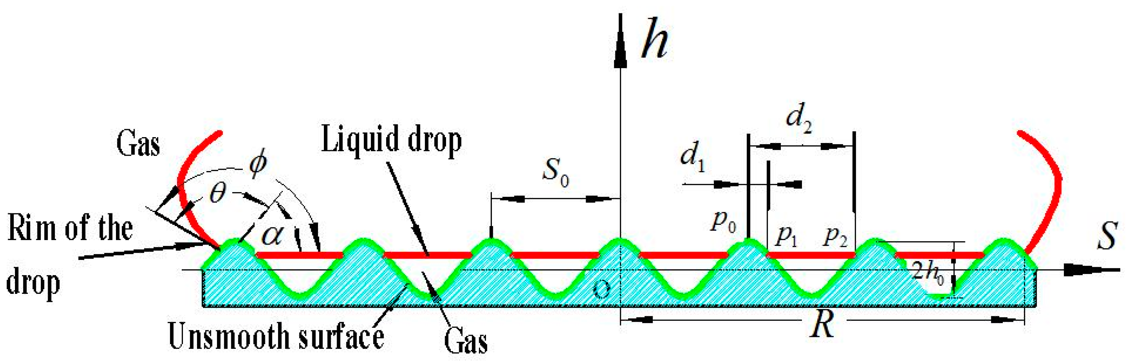
5] have shown that the nonsmooth surfaces of soil animals, whether convex domes or scaly, have a corrugated cross section (Figure 1), which is the common feature.
Here, ϕ is the apparent contact angle; θ is the intrinsic contact angle; and α is the slope angle of the unsmooth wave curve at the rim of the drop (the rim is the profile of wave in the cross section); S0 and h0 are the period and the amplitude of the wave, respectively; S, h, and o are the axes and the origin of the cylindrical coordinates, respectively; p1 and p2 are the points of intersection between each ringlike strip of the gas–liquid interface and its two adjacent waves; p0 is the ridge of the wave near the origin in the above two adjacent waves; d1 and d2 are the distances from p1 to p0 and from p2 to p0, respectively; S0 is the period of the wave; R is the radius of the interface between the liquid drop and the unsmooth surface; and S, h, and o are the axes and the origin of the cylindrical coordinates, respectively.
As Jia [30] described, the equation for the cross section of the unsmooth surface through the origin is
h = h 0 cos 2 π S S 0
Figure 1 indicates that
tan α = d h d S
The conditions for forming a composite interface between a liquid and a nonsmooth surface (Figure 1) are [31] as follows:
θ = ϕ | α |
where α is the slope angle of the unsmooth wave curve at the rim of the drop.
Hence
α = arctan ( 2 π h 0 S 0 sin 2 π S S 0 )
Equation (4) suggests that the larger the value of h0/S0 is, the larger the value of |α|; therefore, given the relationship between θ and |α|, the larger the value of |α| is, the smaller the value of θ. Hence, for the unsmooth surface, the larger the value of h0/S0 is, the larger the apparent contact angle of liquid drop , the stronger their hydrophobicity, the easier the formation of composite interface between the soil and the unsmooth surfaces, and the better the ability to reduce soil adhesion. These properties indicate that the larger the value of h0/S0 is, the easier the formation of the composite interface. Figure 1 indicates that, after the composite interface forms, the real contact area between the soil and the unsmooth cuticles will decrease, and some of the contact area is replaced by the interface between the soil and the gas. Clearly, soil adhesion will decrease greatly [30].
According to the water film tension theory of soil adhesion [32], the formation of the composite interface can significantly reduce the contact area between the soil’s water and the nonsmooth surface on the contact surface, which is beneficial to the antiadhesion and drag reduction of soil animals. When the composite interface forms, the apparent contact angle and the intrinsic contact angle θ can be expressed as [33]:
cos ϕ = r cos θ η
where r’ is the ratio of the real contact interface area between the soil and the rough surface to the projected area of the rough surface and η is the ratio of the contact interface area between the liquid and the gas under the liquid drop to the projected area of the rough surface.
Figure 1 shows that the shape of the gas–liquid interface is a ringlike strip. Each ringlike strip interface and its two adjacent waves intersect at p1 and p2, and the ridge of the adjacent wave near the origin is denoted by p0. The distances from p1 to p0 and from p2 to p0 are d1 and d2, respectively. Correspondingly, m1 and m2 are the ratios of d1/S0 and d2/S0, respectively. Therefore, the width parallel to the S axis of each strip is (m2-m1)∙S0. The total area of all the strips shows the area occupied by the gas–liquid interface. Therefore, the area of the gas–liquid contact interface under the liquid drop is
A g 1 = n = 1 N 1 { π [ ( n 1 ) + m 2 ] 2 S 0 2 π [ ( n 1 ) + m 1 ] 2 S 0 2 } = π S 0 2 n = 1 N 1 { [ ( n 1 ) + m 2 ] 2 [ ( n 1 ) + m 1 ] 2 }
where Ag1 is the interface area between the gas and the liquid at the composite interface, n is the nth wave, and N is the number of waves covered by the liquid drop.
The projected area of the rough surface Ap is
A p = π R 2
Hence, according to the definition of η, η can be expressed as
η = A g l A p = π S 0 2 n = 1 N 1 { [ ( n 1 ) + m 2 ] 2 [ ( n 1 ) + m 1 ] 2 } π R 2 = S 0 2 R 2 n = 1 N 1 { [ ( n 1 ) + m 2 ] 2 [ ( n 1 ) + m 1 ] 2 }
The real contact interface area between the soil and the rough surface can be calculated as follows:
A sl = n = 1 N 1 { n S 0 ( n + m 1 ) S 0 2 π S [ 1 + ( d h d S ) 2 ] 1 2 d S + ( n + m 2 ) S 0 ( n + 1 ) S 0 2 π S [ 1 + ( d h d S ) 2 ] 1 2 d S } + N S 0 R 2 π S [ 1 + ( d h d S ) 2 ] 1 2 d S = 2 π n = 1 N 1 { n S 0 ( n + m 1 ) S 0 S [ 1 + ( d h d S ) 2 ] 1 2 d S + ( n + m 2 ) S 0 ( n + 1 ) S 0 S [ 1 + ( d h d S ) 2 ] 1 2 d S } + 2 π N S 0 R S [ 1 + ( d h d S ) 2 ] 1 2 d S
Here,
n S 0 ( n + m 1 ) S 0 S [ 1 + ( d h d S ) 2 ] 1 2 d S = ( n + m 2 ) S 0 ( n + 1 ) S 0 S [ 1 + ( d h d S ) 2 ] 1 2 d S
N S 0 R S [ 1 + ( d h d S ) 2 ] 1 2 d S ( n + m 2 ) S 0 ( n + 1 ) S 0 S [ 1 + ( d h d S ) 2 ] 1 2 d S
Let,
n S 0 ( n + m 1 ) S 0 S [ 1 + ( d h d S ) 2 ] 1 2 d S = ( n + m 2 ) S 0 ( n + 1 ) S 0 S [ 1 + ( d h d S ) 2 ] 1 2 d S = a n
Thus, from Equations (11) and (12), we can obtain
N S 0 R S [ 1 + ( d h d S ) 2 ] 1 2 d S a n
Substituting Equations (12) and (13) into Equation (9),
A sl 2 π n = 0 N 1 2 a n + 2 π a n = 2 π ( n = 0 N 1 2 a n + a n )
Based on the definition of r’, Equations (7) and (14),
r = A sl A p = 2 π ( n = 0 N 1 2 a n + a n ) π R 2 = 2 R 2 ( n = 0 N 1 2 a n + a n )
a n = a n 1 = = a 0 = 0 m 1 S [ 1 + ( d h d S ) 2 ] 1 2 d S = 0 m 1 S 0 S [ 1 + 4 π 2 h 0 2 S 0 2 sin 2 2 π S S 0 ] 1 2 d S
Therefore, Equation (16) shows that the larger the value of h0/S0 is, the larger the an, and the larger the value of r’ as well (see Equation (15)). Equation (5) can be used to find that the influence of the r’on the apparent contact angle is similar to that of r in cos =rcosθ [34], where is the apparent angle of the drop on the rough surface, θ is the intrinsic angle of the drop on the rough surface, and r is the roughness factor of the surface, which equals the ratio of the real area of the rough surface to the projected area of the rough surface. The value of r should be larger than 1.
For the unsmooth cuticles of soil animals, the larger the ratio of the wave amplitude to the wave period (h0/S0) is, the larger the apparent contact angle of the liquid drop (), the easier the formation of a composite interface between the soil and the unsmooth cuticles, and the better the ability to reduce soil adhesion.
From the above theoretical analysis, during the bionic design of the potato digging shovels, the height of bionic structure h (which corresponds to h0) and the spacing of its arrangement Si (which corresponds to S0) are the key parameters for designing bionic drag reduction performance tools.

2.2. Structural Design of Bionic Potato Digging Shovel

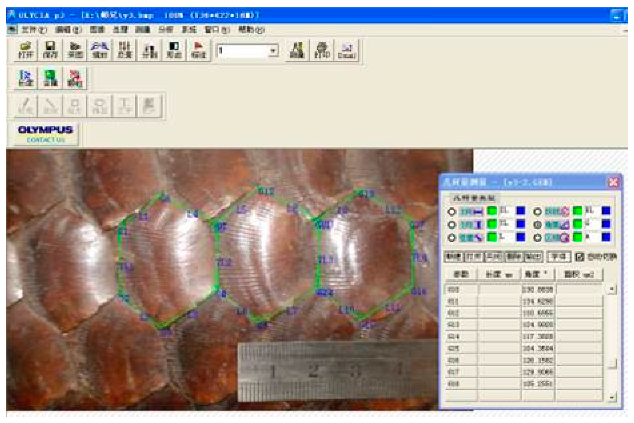
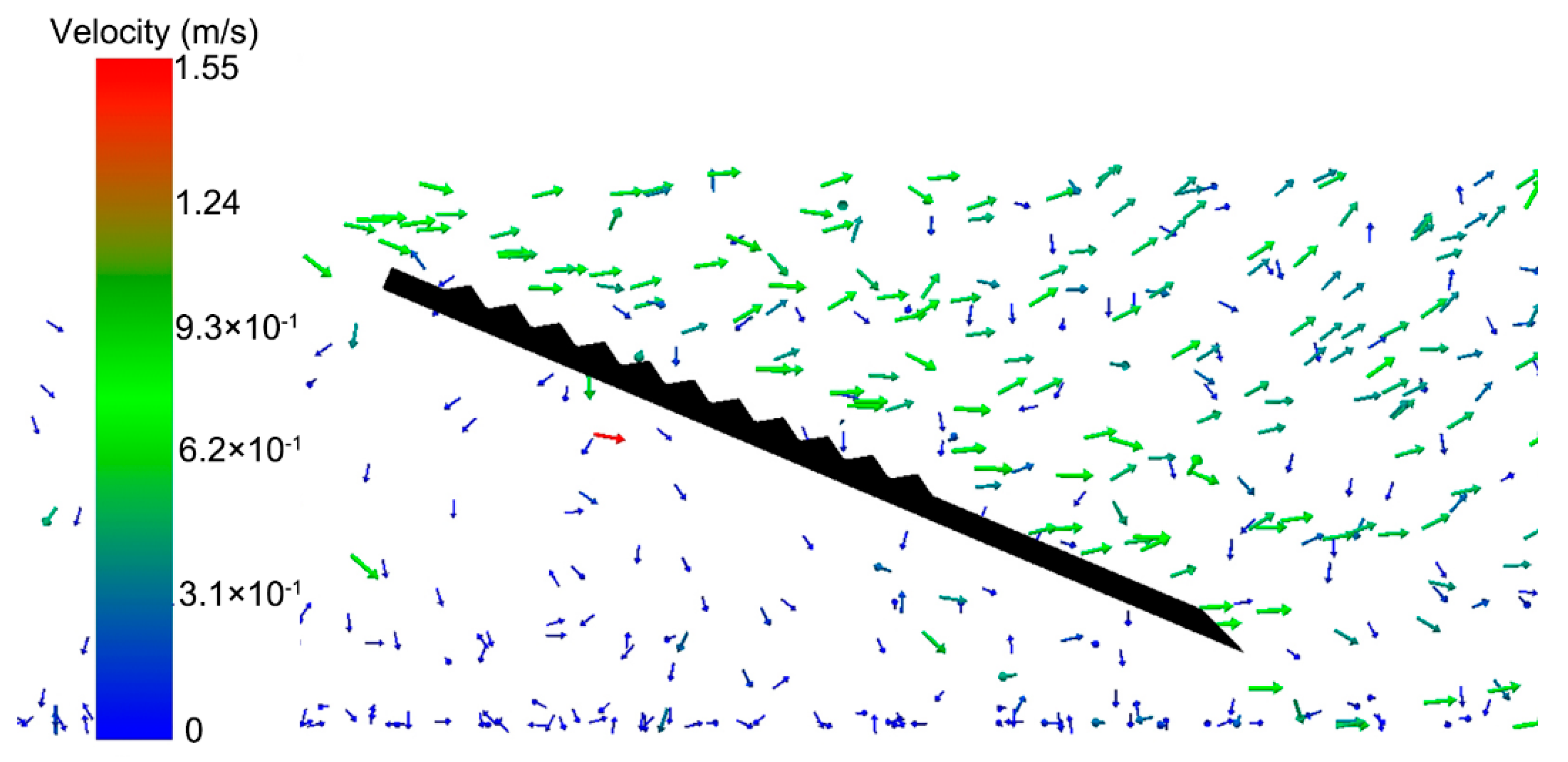
The pangolin is a typical soil animal. The scalelike unit structure of the pangolin can achieve effective drag reduction. According to the results of previous work by our research group [9,10], the bionic digging shovel inspired by the structure of pangolin scale units (
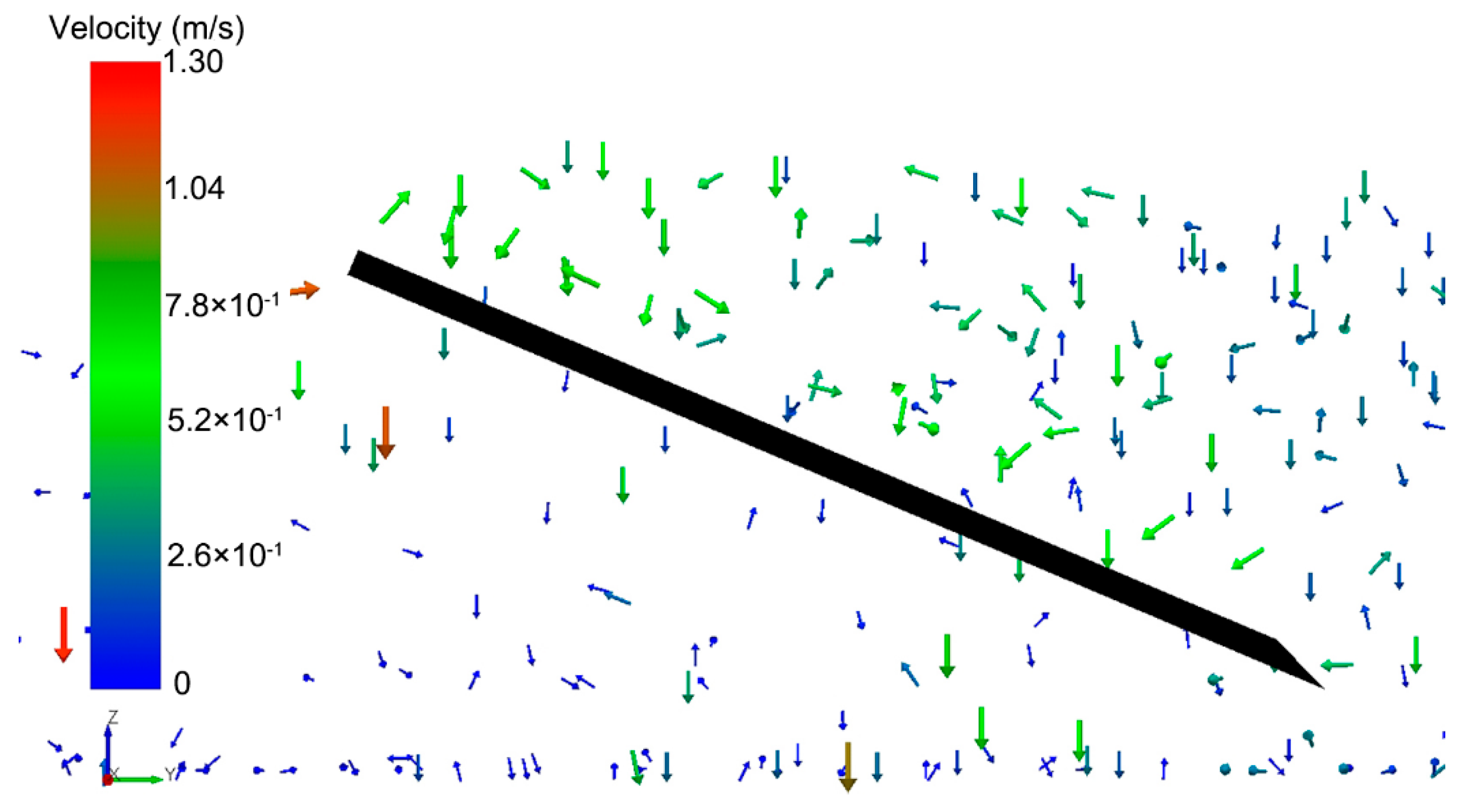
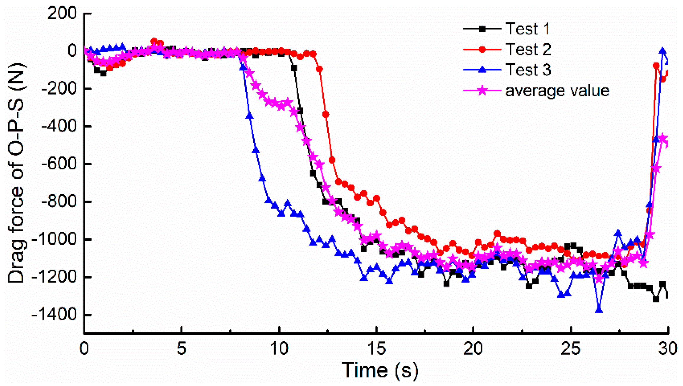
Figure 2) were designed (labeled S-U-S) according to the structure and scale of pangolin scales. Besides, an ordinary plane shovel (labeled O-P-S) was designed as the comparison and the outline structure of the O-P-S is shown in Figure 3.
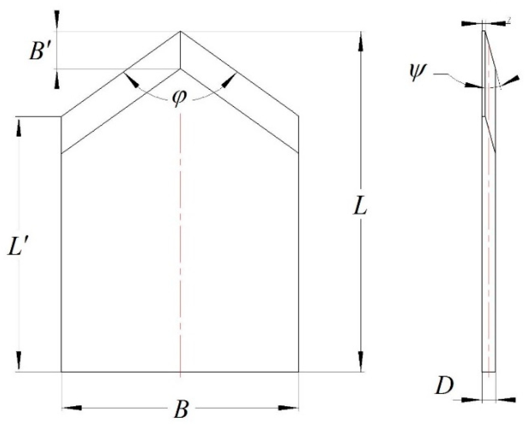
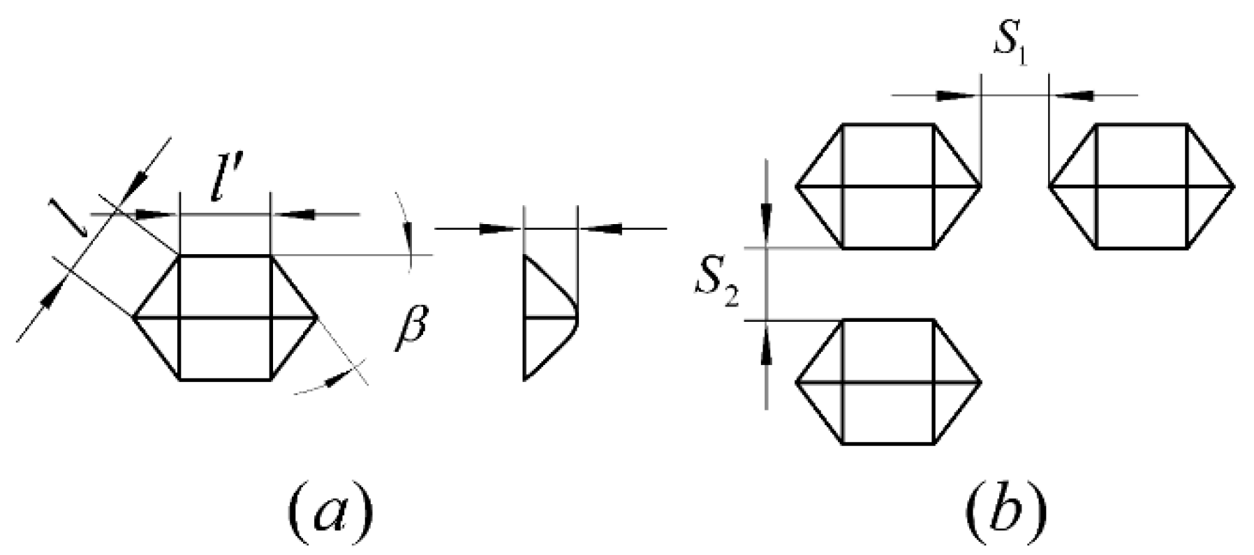
Based on a theoretical analysis of the anti-soil-adhesion mechanism, the height (h) of the bionic structure and its arrangement spacing (Si) are the critical design parameters that affect the drag reduction performance of the potato digging shovel. As shown in Figure 4, the bionic shovel was designed by a similar theory. The primary design parameters of the scalelike unit are the length (l) or (l), height (h) and side angle (β), as shown in Figure 4. In this paper, the length (l) and the height (h) are used as the structural design variables.
Here, l’/l = 1.175, β = 53° (
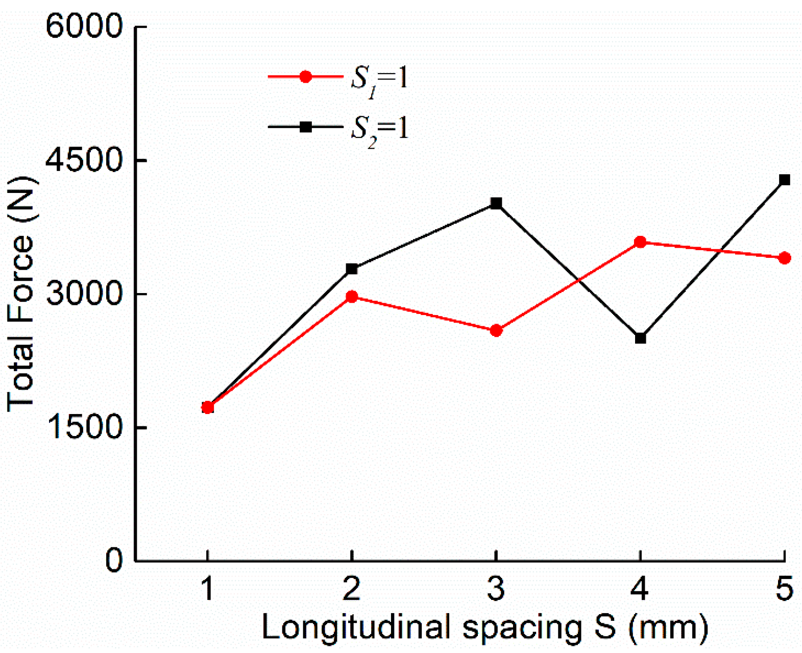
Figure 4). The bionic shovel with the bionic scalelike unit structure was designed by arranging the unit structures on the soil-contacting surface of the potato digging shovel. The arrangement parameters are the transversal spacing S1 and longitudinal spacing S2, as shown in Figure 4b.

2.3. Selection of Clayey Soil Particles Model for DEM

The Hertz–Mindlin (no slip) contact model in the EDEM software is too simple to use when using DEM to simulate the movement of soil particles. Because this contact model only considers the rigid contact of the particles similar to the contact of two steel balls, it is obviously not suitable for simulating soil particles. Particularly in the potato-growing areas of Northeast China, the tilled soil is sticky and agglomerates easily. This soil often adheres to the surface of potato digging shovels. The “Hertz–Mindlin with JKR” contact model is based on the JKR theory, considers the influence of the inter-wet-particle adhesion force on the particle motion law. It is a cohesive force contact model, which is suitable for simulating materials with obvious adhesion and agglomeration due to static electricity, moisture, etc., such as crops and wet soil [28]. The parameters for the contact model were based on the data in the literature, as listed in Table 1.

2.4. Design of Simulation Experiments

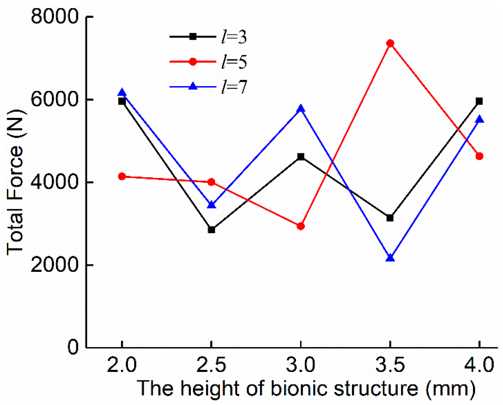
There are four primary design variables for the bionic potato digging shovel, i.e., the length l, height h, and arranged spacing Si (i = 1, 2) of the bionic structure. Each variable can have multiple levels. That design will lead to a large number of trials for a fully aligned combination design, which greatly increases the simulation workload. Among the influencing factors of the reduction of tillage resistance, the influence of the bionic structural parameters on the tillage resistance is significantly greater than that of the arrangement spacing. With the best drag reduction biomimetic structure parameters (l, h), if the shovel with the arrangement spacings (S1, S2) does not reduce the resistance, then, for the bionic structural parameters (l, h) with non-resistance-reduction, which are under the same arrangement spacing combination (S1, S2), it should be non-resistance-reduction as well. This factor finding order can reduce unnecessary simulations. Hence, a preliminary simulation experiment was performed in this paper by using the control variables and parallel comparison methods. The specific method was as follows. First, we set a uniform arrangement spacing and then, studied the effect of the biomimetic structure parameters l and h on the drag reduction performance. The biomimetic structural parameters with the optimal drag reduction performance were obtained through simulations. Then, assuming that the optimal drag reduction structure is known, the influence of the arrangement of the bionic structure on the drag reduction performance was simulated. Finally, the structural parameters and the arrangement spacing parameters with the best drag reduction performance were obtained. Hence, the effects of the biomimetic structural parameters as well as the transversal and longitudinally arranged spacings on the drag reduction performance of potato digging shovel under clayey soil conditions were discussed. The purpose was to obtain a suitable range of the bionic drag reduction structure parameters and their arrangement spacing, which provided basic parameters for subsequent design optimization and physical experiment. The engineering application range of the parameters and the range of optimization parameters are given.
First, the arrangement spacing between the scalelike unit structures was set as S1 = S2 = 1 mm. The parameters for length l and height h were set as the design variables. Thus, the effects of the bionic structure on the drag reduction performance were compared. The design of the simulations for the S-U-S are listed in Table 2.
Second, after the previous simulations on the basis of the first step, the optimal solution for drag reduction regarding the height and length parameters of the scalelike unit structure can be obtained. Then, on the basis of the determined bionic structure, the simulations were performed by designing the spacing variable. At last, the optimal simulation result of the drag reduction was the final result for the parallel comparison with other biomimetic structures.

2.5. Identification Experiemts

Through the above simulation test, the best drag reduction bionic structure is obtained, and the physical sample is manufactured according to the bionic structure. The drag reduction performance of the bionic digging shovel was verified by the soil bin test and the field test.

2.6. Soil Bin Test

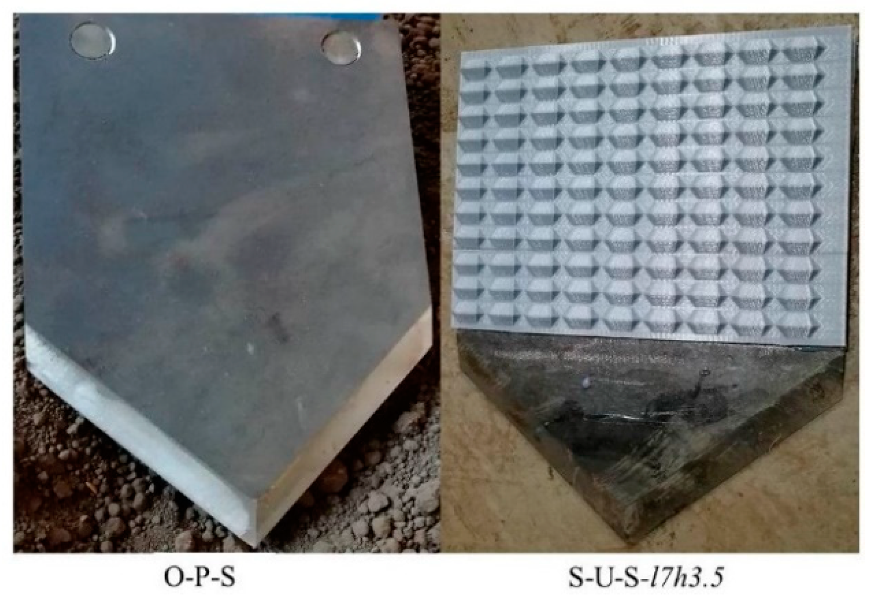
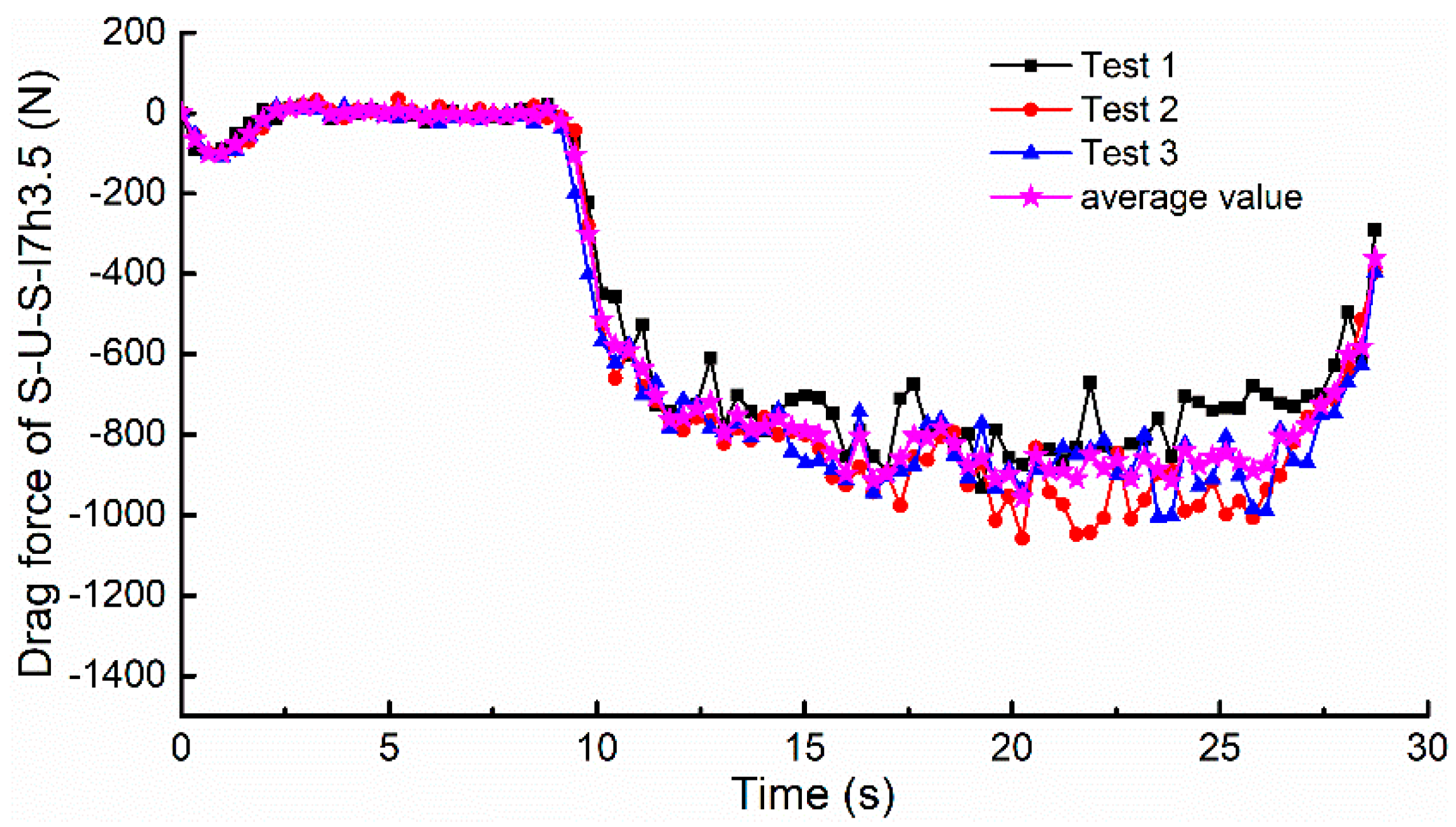
To verify the drag reduction performance of the bionic digging shovel preliminarily, a bionic digging shovel of the S-U-S-l7h3.5 which the l and h of the bionic structure was 7 mm and 3.5 mm respectively, with arranged spacing of S1 = S2 = 1 mm was prepared and the O-P-S was used as a comparison. The O-P-S was manufactured by a numerical control machine (CNC) machine tool and its material was 40MnB or 45 steel, as shown in 
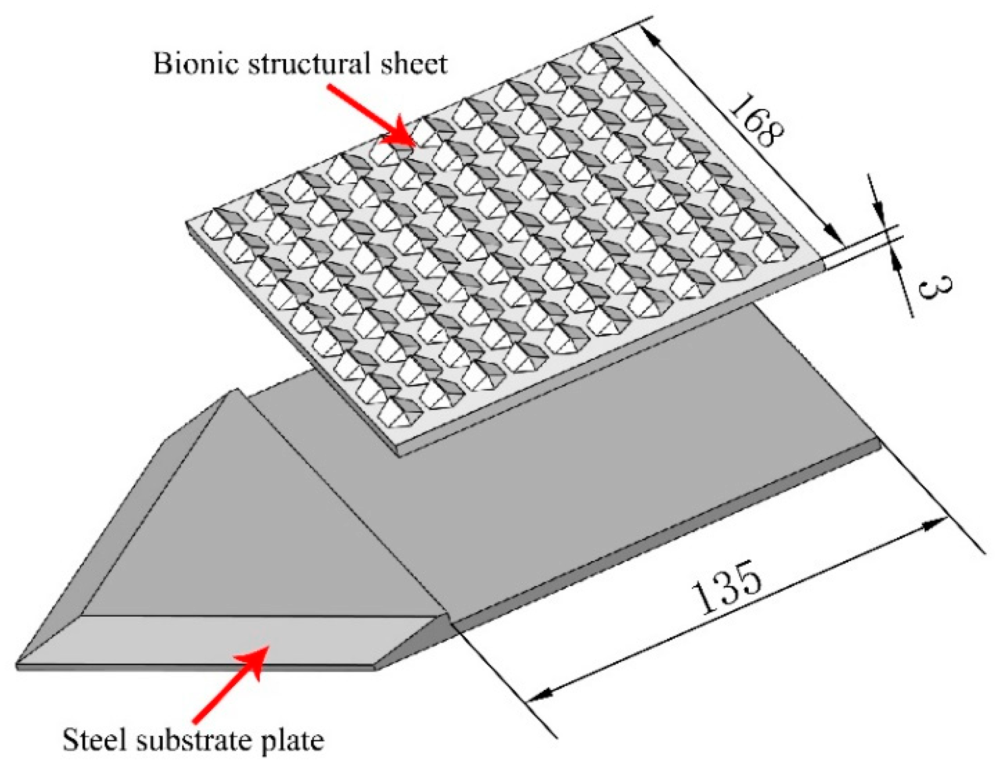
Figure 5. The bionic shovel was obtained as follows. (1) A flat shovel of the same size as the O-P-S was set as the substrate and machined by a steel plate. In the area where the bionic structural sheet is placed on the substrate plate, a flat-bottomed groove with measuring 135 mm × 168 mm × 3 mm was cut by a CNC machine. (2) A bionic structural sheet (135 mm × 168 mm × 6.5 mm) with pangolin scale structures was manufactured by 3D printing. (3) The steel substrate plate and the bionic structural sheet were joined by bolts and cementing. The process is shown in Figure 6.
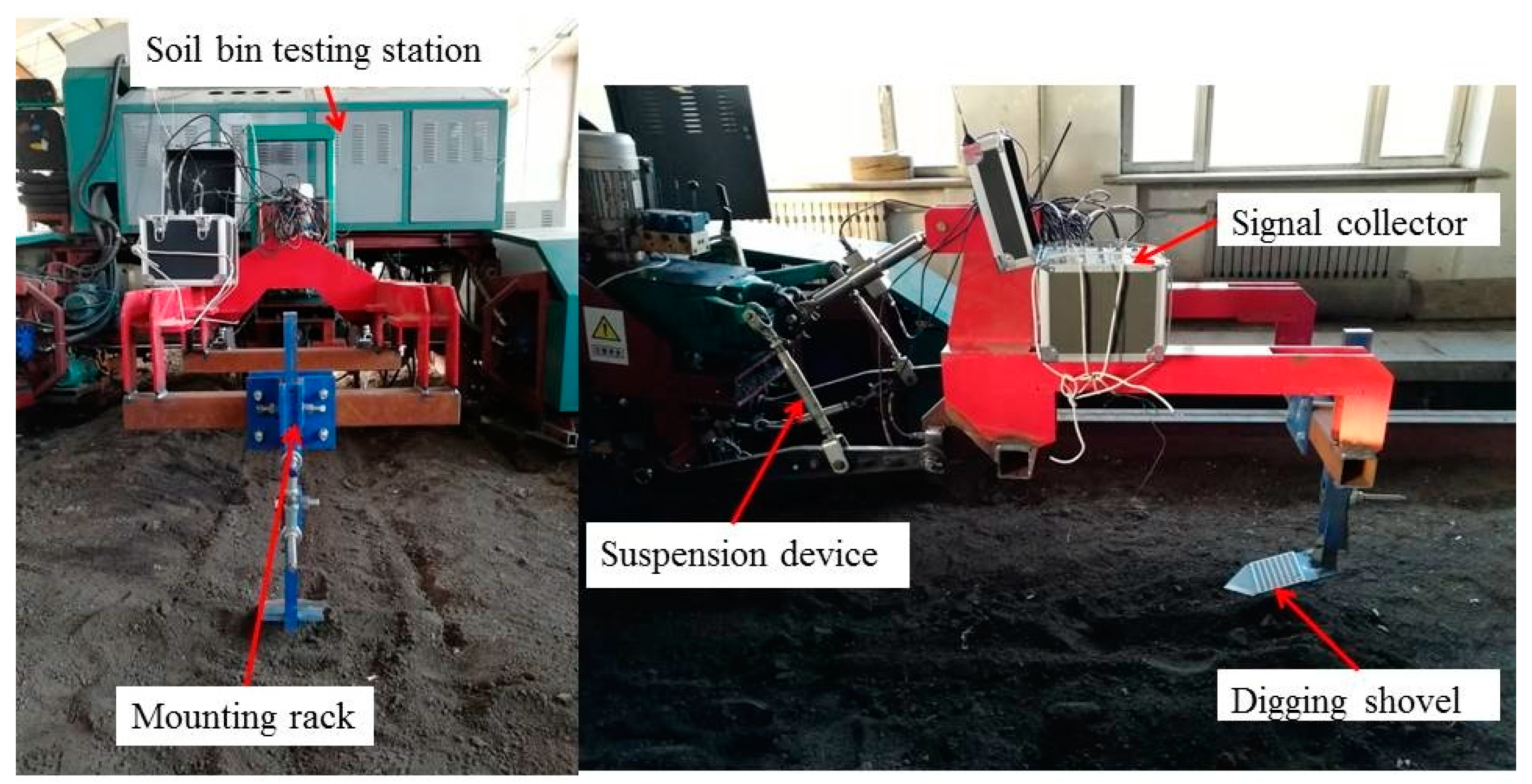
The soil bin test platform is shown in Figure 7. The entire verification test was performed at the soil bin laboratory in the Heilongjiang Agricultural Machinery Engineering Research Institute in Heilongjiang Province, China. The testing parameters are listed in Table 3.

2.7. Field Verification Experiment

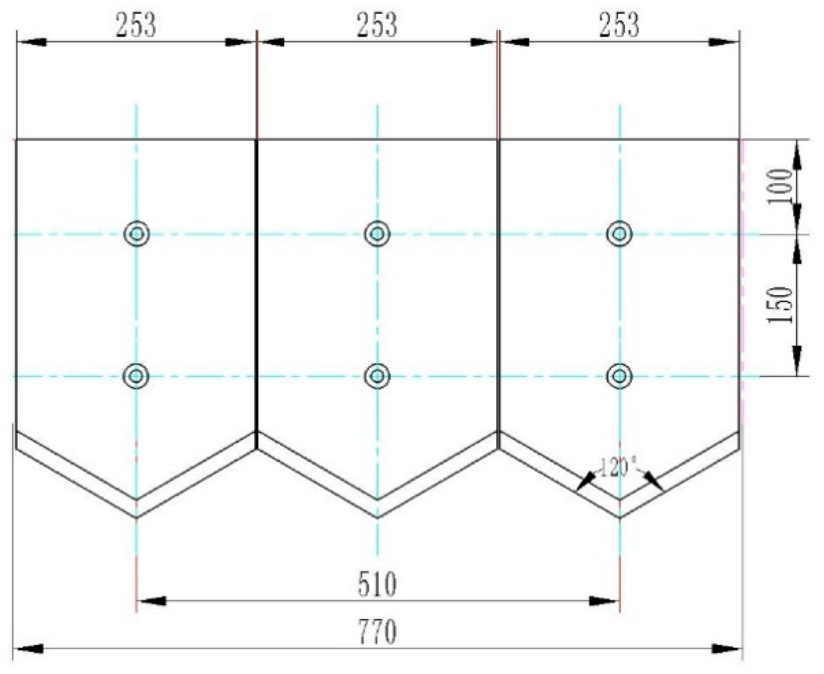
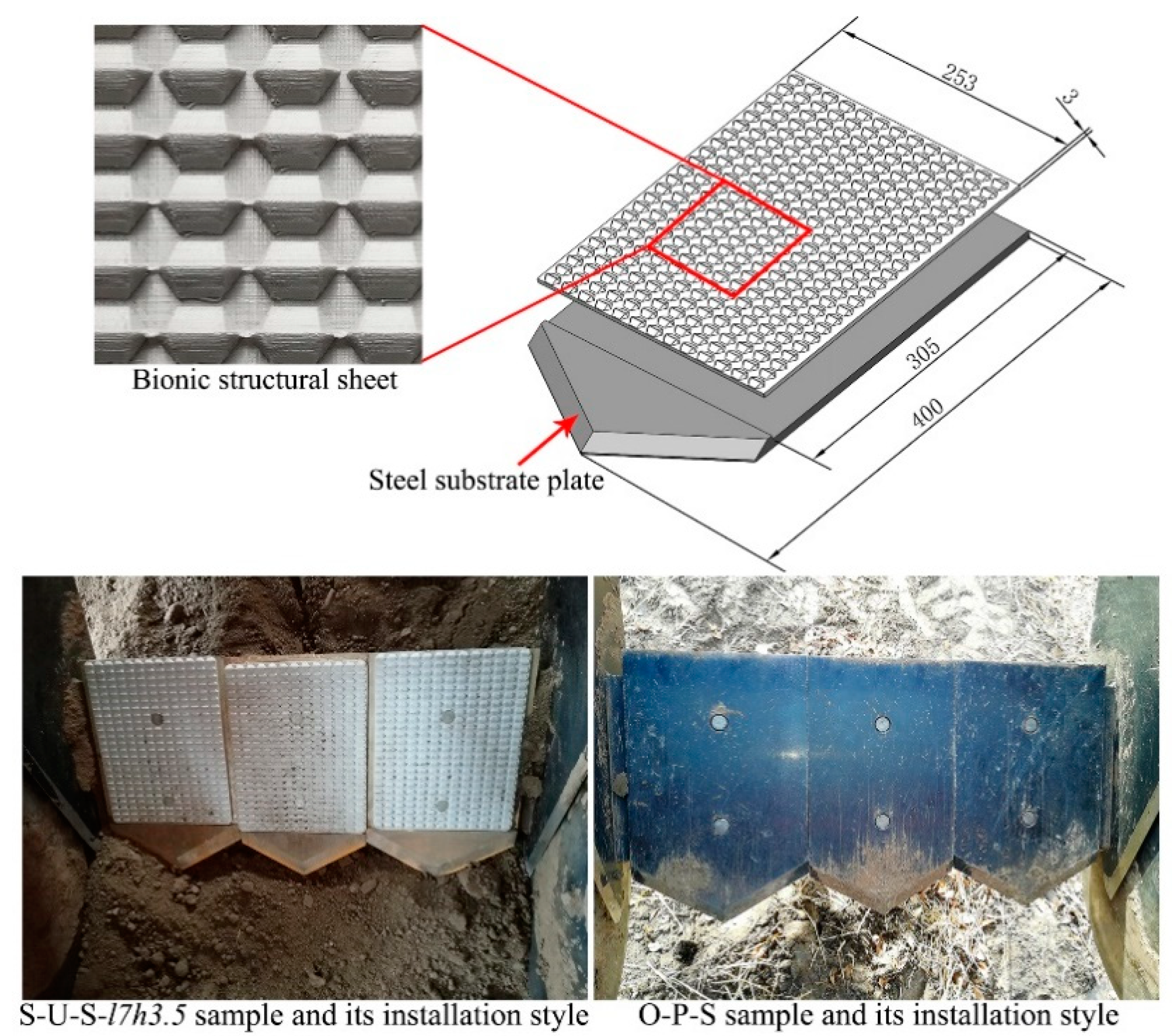
To verify the drag reduction performance of the bionic shovel, a field performance verification was conducted. The experimental field was the potato planting field at Heilongjiang Agricultural Machinery Engineering Research Institute. To match the existing potato digger, the digging shovel needed to be redesigned. The potato excavation device used for the field trial was a 4MLS-2.2 single-row potato excavator, and the working width was 800 mm. One device was equipped with three shovels and each shovel measured 400 mm × 253 mm × 8 mm. The 2D design drawing and its installation style are shown in Figure 8.
The O-P-S was manufactured by a CNC machine tool and its material was 40MnB or 45 steel. The bionic shovel was obtained as follows. (1) A flat shovel of the same size with the O-P-S was set as the substrate, which was machined by a steel plate. In the area where the bionic structural plate is placed on the substrate steel plate, a flat-bottomed groove measuring 305 mm × 253 mm × 3 mm was cut by a CNC machine. (2) A bionic structural sheet (305 mm × 253mm × 6.5 mm) with a plurality of pangolin scale structures was obtained by 3D printing. (3) The steel substrate plate and the bionic structural sheet were joined by bolts and cementing. This process is shown in Figure 9.
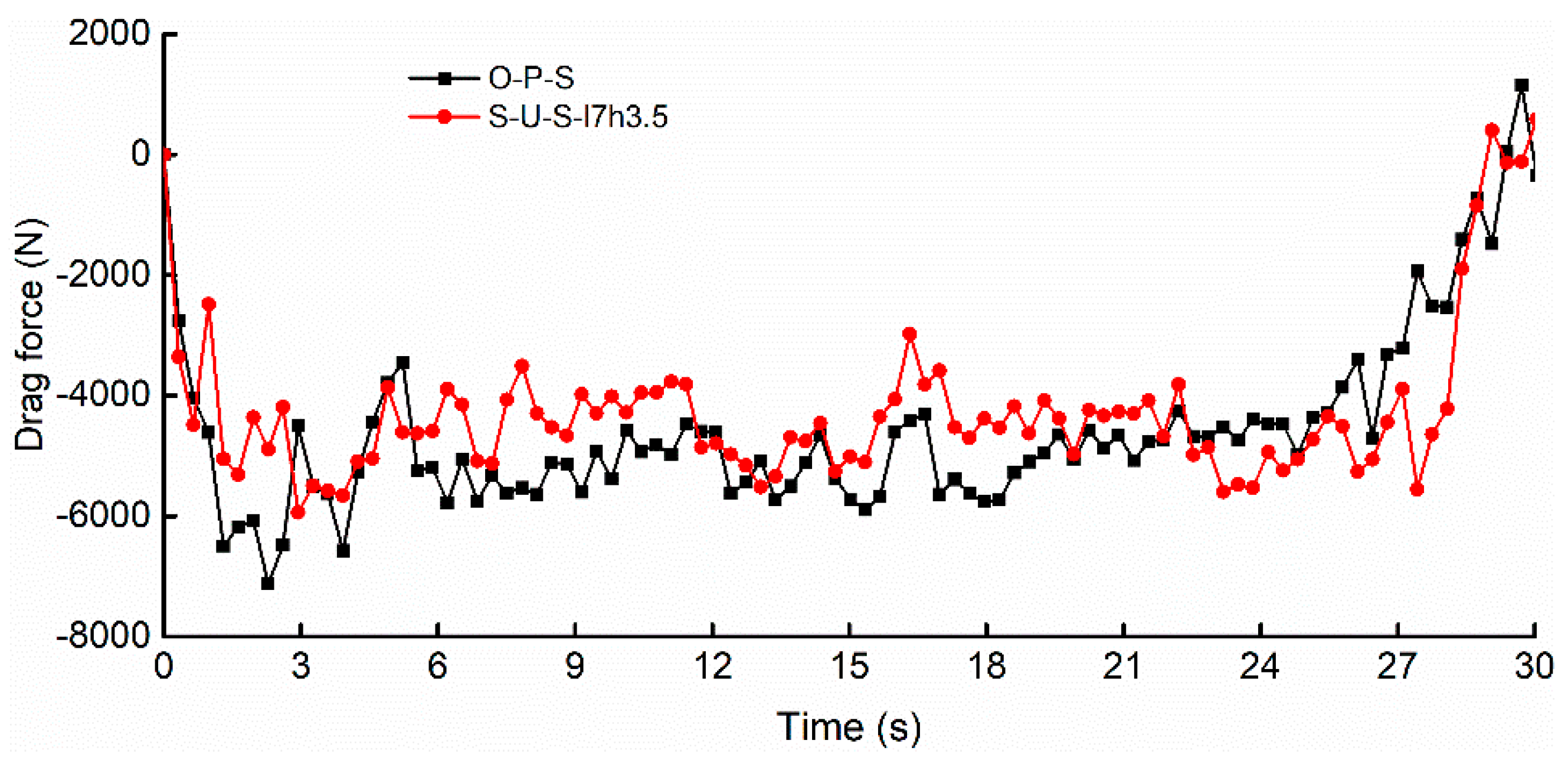
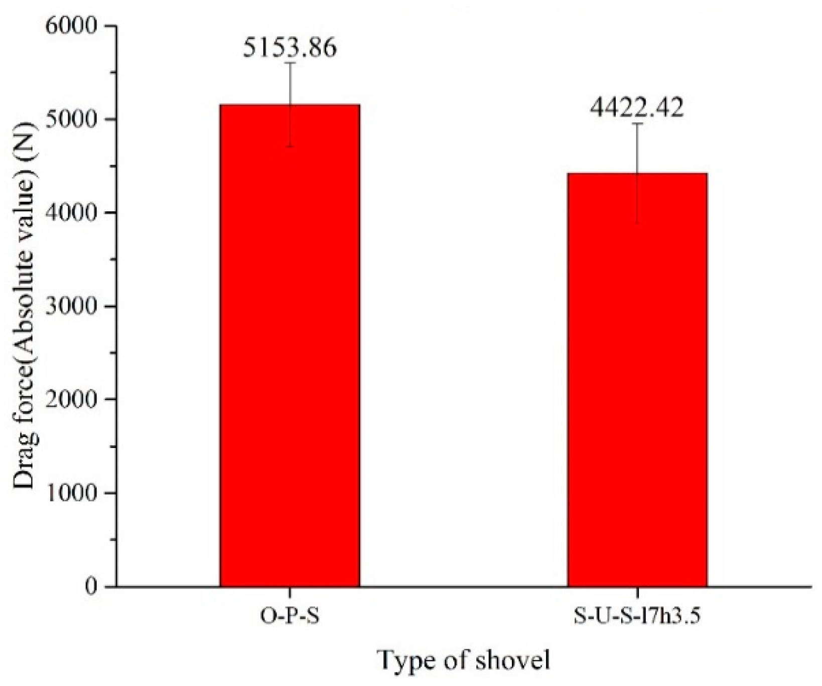
To reduce the test error, the testing requirements for the conditions of the field ridge were as follows: the soil compactness measurements of the two ridges were similar and so were the soil moisture contents; the ridge shapes of the two ridges were similar to each other. The length of each ridge in the field was approximately 70.00 m. One ridge was the test site of the O-P-S and the other ridge was the test site of the S-U-S-l7h3.5. The soil compaction was measured by using a handheld soil compactness meter (Field Scout SC-900, Spectrum Technologies, Aurora, Illinois, USA), and the soil moisture content was measured with a handheld soil moisture meter (Field Scout TDR-300, Spectrum Technologies, Aurora, Illinois, USA). The field performance test parameters are listed in 
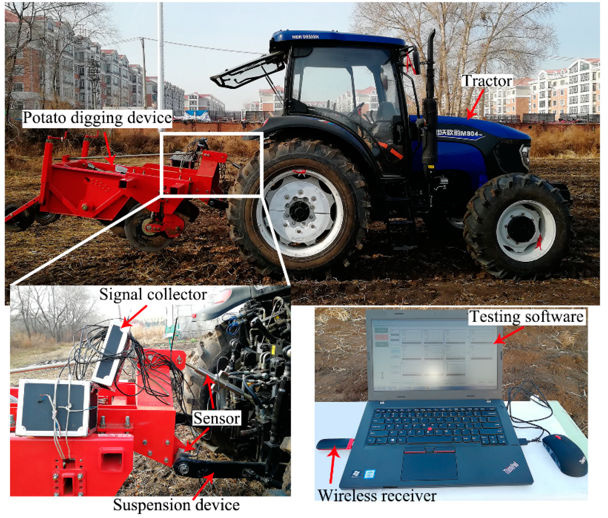
Table 4. The test system for the field performance test is shown in Figure 10.

3. Results and Discussion

According to the results of simulations, the bionic digging shovels (labeled S-U-S) were simulated using EDEM2.5 software [29,35]. The total force, draft force in the moving direction and the compress force were used as the test indicators to compare the corresponding forces of the ordinary plane shovel (O-P-S).

3.1. Simulation Results and Analysis of S-U-S

3.1.1. Forces as Affected by the Different Biomimetic Structure Parameters

According to the scheme listed in Table 2, 15 groups of discrete element simulations were performed with different structure parameters of S-U-S. The total force, draft force in the forward direction and the vertical force were used as the test indicators to compare the corresponding forces of O-P-S. The simulation results are listed in Table 4.
From Table 4, it is clear that the structure of No. 14 was the bionic structure with the best drag reduction performance, with results of TF (total force) = 2159.02 N, DF (draft force) = −1728.91 N (the negative sign indicates that the direction of the force is opposite to the direction of the movement) and CF (compressive force) = 2100.03 N. The scalelike unit structure with the best drag reduction was labeled as S-U-S-l7h3.5, for which the structural parameters were l = 7 mm and h = 3.5 mm and the arranged spacing was S1 = S2 = 1 mm. For the O-P-S, the corresponding values were TF = 2930.81 N, DF = −2275.92 N, and CF = 2100.03 N, and so the force values of the S-U-S-l7h3.5 were reduced by 26.33%, 24.03% and 26.91%, respectively.
To explore the influence of the scalelike unit structure parameters on the drag reduction performance, a preliminary analysis of the above 15 groups of results was performed. Variations of the total force changing with the height for different lengths were investigated, as shown in Figure 11.
As shown in Figure 11, when the length of the scalelike unit structure was 3 mm, the total force had a tendency to decrease significantly as the height (h) increased from 2 mm to 4 mm. However, h = 3.5 mm was a turning point. When h > 3.5 mm, the total force showed an increasing trend.
It is clear that, when the length of the scalelike unit structure was 5 mm, the total force had a tendency to decrease as the height h increased from 2 mm to 3 mm. However, h = 3 mm was a turning point. When h > 3 mm, the total force showed an increasing trend.
When the length of the scalelike unit structure was 7 mm, the total force had a tendency to decrease significantly as the height h increased from 2 mm to 4 mm. However, h = 3.5 mm was a turning point. When h > 3.5 mm, the total force showed an increasing trend. When l = 7 mm and h = 3.5 mm, the total force reached the minimum value TF = 2159.02 N.
From Figure 11, both the height and the length parameters of the scalelike unit structure had an important influence on the drag reduction performance. It is worth mentioning that when the height of the structure exceeded 3.5 mm, the total force increased significantly.
After the preliminary analysis, to obtain a better drag reduction performance, the range of structural parameters we recommend is 5 mm < l < 8 mm, 2 mm < h < 4 mm. Based on this finding, the structural parameters can be further optimized.

3.1.2. Forces Affected by the Different Arrangement Spacing of the Optimal Structure

The structural parameters of No. 14 in Table 2 were l = 7 mm, h = 3.5 mm when the arrangement spacing was fixed at S1 = S2 = 1 mm. We followed the steps of the simulation experimental design for the S-U-S as stated in the design of simulation experiments section. Here, the next simulation was performed by changing the arranged spacing of the bionic structure, which was labeled S-U-S-l7h3.5. According to Table 3, 16 groups of discrete element simulations were performed with different arranged spacings for S-U-S-l7h3.5. Because the draft force was consistent with the tractor traction in format (they are both along the direction of movement), in this research, the draft force was used as the reference value to study the influence of the arranged spacing of the scalelike unit on the drag reduction performance. The simulation results are listed in Table 5.
To investigate the influence of the arrangement of the scalelike unit structure on the drag reduction performance, a single factor, such as the lateral spacing or the longitudinal spacing, was analyzed according to the predesigned test plan. As shown in Figure 12, when the longitudinal spacing was fixed (S2 = 1 mm), the total force tended to increase as the lateral spacing increased. As shown in Figure 12, when the transversal spacing was fixed (S1 = 1 mm), the total force tended to increase as the longitudinal spacing increased. The above results showed that the arrangement of scalelike unit structures also had a great influence on the drag reduction performance. Theoretically, the smaller the spacing is, the greater the drag reduction. This finding was consistent with the theoretical analysis. As the spacing size and structural size continue to decrease, the manufacturing cost and design cost are significantly increased, which is impossible in agricultural engineering applications. Hence, the recommended values of the range of the arranged spacing used in engineering applications are 1 mm ≤ S1 4 mm, 1 mm ≤ S2 4 mm.
The above preliminary analysis means that, for the scalelike unit structure, the recommended structural parameters for engineering applications are 5 mm ≤ l ≤ 8 mm and 2.5 mm ≤ h ≤ 3.5 mm, and the recommended ranges of the arrangement spacings are 1 mm ≤ S1 ≤ 4 mm and 1 mm ≤ S2 ≤ 4 mm. To adapt to the engineering applications, the structural parameters can be further optimized based on the resulting suggestions.
In summary, it can be inferred that, when the height exceeds a critical value (h > 3.5 mm), the biomimetic structure is detrimental to the formation of a composite contact interface.
On the contrary, when the bionic structure exceeds a critical value of 3.5 mm, the composite interface cannot be created, and a barrier will form, hindering the continuous movement of soil. Thus, an accumulation of soil at the contacting barrier is formed, resulting in increasing resistance. This result is consistent with the conclusions of the literature [36].

3.1.3. Comparative Analysis of Drag Reduction Bionic Structures

The simulation results obtained by the aforementioned test methods show that, under the appropriate structural parameters and arrangement spacing, the bionic digging shovel can achieve excellent antiadhesion and drag reduction performance. Especially in the case of S1 = S2 = 1 mm, the bionic digging shovel can achieve optimal drag reduction performance. The drag reduction performances of S-U-S-l7h3.5 and the O-P-S are listed in Table 6.
The simulated results indicate that the bionic digging shovel had an excellent drag reduction performance. Compared with the O-P-S, the drag reduction rate of S-U-S-l7h3.5 was larger than 24%.
For the drag reduction phenomenon, the velocity flow of the simulated soil particles can be explained. Figure 13 and Figure 14 shows the velocity flow of soil particles on the O-P-S and S-U-S-l7h3.5, respectively. As shown in Figure 13, the velocity flow of the soil particles on the O-P-S were disorganized and the number of green arrows was also less than that of the bionic shovel. Moreover, the velocity of soil particles was mostly less than 0.788 m/s (green and blue arrows shown in Figure 13. It is notable that the speed of the shovel is 0.84 m/s. However, the speed of the soil particles moving on the O-P-S was generally less than that of the shovel. This finding obviously indicated that the soil particles were deposited on the shovel, which led to an overall decrease in the velocity flow and the possibility of blocking the movement of the soil particles. This result explained why the resistance of the O-P-S was larger than that of the bionic shovels. Similarly, as shown in Figure 14, the soil particles on the bionic shovel show a good fluidity (with attention to the direction of the arrow, the flow of the arrows is consistent.). The velocity flow of the particles was greater than the 0.84 m/s movement speed of the shovel. The velocity flow of the S-U-S-l7h3.5 was approximately 0.942 m/s. This finding indicated that the soil particles on the bionic shovels presented good fluidity. High kinetic energy can cause the soil particles on the shovel surface to avoid siltation. Therefore, the bionic shovel exhibits a good antiadhesion and drag reduction performance.

3.2. Result of the Physical Verification Test

3.2.1. Soil Bin Test

The bionic shovel S-U-S-l7h3.5 and the O-P-S were tested separately according to the soil bin test design. Each type of shovel was tested three times, and the average value of the three tests was used as the final value. The curves of the test results are shown in Figure 15 and Figure 16 (the negative value in the figures indicated that the direction of the force was the opposite of the direction of movement), respectively.
As shown in Figure 15 and Figure 16, the time ranging from 17 s to 26 s can be regarded as the steady working time of the shovel. To analyze the drag reduction performance of the bionic shovel and the ordinary shovel, the average values of the testing results were analyzed at 17–26 s, respectively, as listed in Table 7.
Table 7 clearly shows that the average traction resistance of O-P-S was 1117.78 ± 32.88 N and the average traction resistance of S-U-S-l7h3.5 was 868.95 ± 38.20 N. It was calculated that the drag reduction rate of S-U-S-l7h3.5 was 22.26% compared to the O-P-S. Hence, it can be concluded that the S-U-S-l7h3.5 had a better drag reduction performance than the O-P-S.
In summary, the physical verification test fully indicated that the bionic design of the digging shovel was feasible. This result laid the foundation for a systematic design and further research on the bionic digging shovel in the future.

3.2.2. Field Performance Verification Test

According to the above field performance test design, the bionic shovel S-U-S-l7h3.5 and the O-P-S were tested separately. The curves of the test results are shown in Figure 17 (the negative value indicates that the direction of the force was the opposite of direction of movement).
As shown in Figure 17, the time ranging from 7 s to 20 s can be regarded as the steady working time of the shovel. Hence, the average values of the testing results were analyzed at 7–20 s, as shown in Figure 18.
Figure 18 shows that the average traction resistance of O-P-S was 5153.86 N and the average traction resistance of S-U-S-l7h3.5 was 4422.42 N. It was calculated that the drag reduction rate of S-U-S-l7h3.5 was 14.19% compared to the O-P-S. Hence, the S-U-S-l7h3.5 had a better drag reduction performance than the O-P-S.

3.3. Discussion

In reference to the theoretical analysis described in the Section 2.1, it is clear that the biomimetic structure exhibited excellent antiadhesion and resistance reduction properties within a suitable range of parameters. Here, h0 corresponds to the height h of the bionic structure, and S0 corresponds to the width B of the bionic structure plus the transversal spacing S1 (or the longitudinal spacing S2). As Equation (3) suggests, for the unsmooth surface, the larger the ratio of the wave amplitude to the wave period is h0/s0, the easier the formation of the composite interface between the soil and the unsmooth surface and the better the reduction soil adhesion. That finding indicates that the larger the value of h0/s0 is, the easier the formation of the composite interface. These results are in agreement with the research of Li and Zhai [2,3]. Thus, for the bionic structure, the size of the bionic structure is given, i.e., the height and width are given. For an S-U structure, its width B can be calculated from the side length l, and its calculation formula is B = l’ + 2∙l∙cos53° = 6∙1.175 + 2∙l∙cos53°. The value of h0/s0 depends on the value of the arrangement spacing Si. The smaller the spacing Si, the larger the h0/s0 is, which indicates that the more favorable the formation of the composite interface is, the more favorable the antiadhesion and resistance reduction effects are. This conclusion is consistent with the simulated results. From the simulated results, the correctness of the theoretical analysis was verified. In this paper, the drag reduction performance of the bionic shovels was when the arranging spacings were S1 = S2 = 1 mm; the resistance was the smallest here. However, for engineering applications, the arrangement spacing of bionic structures should be combined with the economics and manufacturing processability. Spacing that is too small can lead to processing difficulties and significantly increase costs, which is not conducive to engineering practice. Thus, the minimum spacing determined in this paper was 1 mm.
Furthermore, the size of the bionic structure also required a suitable range. Here, it did not mean that the larger the height h of the bionic structure was, the better the drag reduction performance. Through the simulation analysis, it is clear that when the height h of the bionic structure exceeds a certain critical value, the resistance does not decrease but instead increases significantly. This was because, when h exceeded a critical value, the composite interface could not be created, and a barrier formed, hindering the continuous movement of the soil. Therefore, an accumulation of soil at the contact was formed, resulting in increasing resistance.

4. Conclusions

To solve the problem of excessive resistance caused by the soil adhering strongly to the digging shovel in the clayey soil area, a bionic potato-digging shovel (labeled as S-U-S) was designed in this paper. The length l and height h for the bionic structures as well as the transversal and longitudinal arranging spacings (S1 and S2) were taken as the design variables. The influence of the four design variables on the drag reduction performance was primarily investigated by discrete element simulations, which were designed by control variables and a parallel comparison method. The discrete element method (DEM) used cohesion to simulate the antiadhesion and drag reduction performance under clayey soil with high moisture content. The simulated results shown that the drag reduction performance of the bionic shovels was better than that of the O-P-S with suitable parameters. The recommended range of the bionic structural dimensions for engineering applications is given. The recommended parameters for engineering applications are 5 mm ≤ l ≤ 8 mm and 2.5 mm ≤ h ≤ 3.5 mm for the scalelike unit structure, and the ranges of the arrangement spacings are recommended to be 1 mm ≤ S1 ≤ 4 mm, 1 mm ≤ S2 ≤ 4 mm. When the arrangement spacing S1 = S2 = 1 mm, the bionic digging shovel (labeled S-U-S-l7h3.5) had the least resistance and the TF (total force) = 2159.02 N, DF (draft force) = −1728.91 N (negative sign indicates that the direction of the force is the opposite of the direction of movement), and CF (compress force) = 2100.03N. The corresponding values of the O-P-S were TF = 2930.81 N, DF = −2275.92 N, and CF = 2873.20 N. The force values of the S-U-S-l7h3.5 were reduced by 26.33%, 24.03%, and 26.91%, respectively. Finally, the physical verification test fully showed that the bionic design of the digging shovel was feasible. The results of the physical test showed that the bionic sample labeled as a bionic prototype based on the S-U-S-l7h3.5 had a 22.26% drag reduction rate during the soil bin test and a 14.19% drag reduction rate during the field test compared to the O-P-S. In this paper, the appropriate parameter ranges of the bionic structures were obtained, which provides the basic reference data for the engineering application and optimization of the structural parameters of the bionic shovels.

Author Contributions

Investigation, J.L.; project administration, B.H.; software, X.J.; supervision, Y.M.; visualization, J.T.; writing—original draft, J.L.; writing—review and editing, X.J. All authors have read and agreed to the published version of the manuscript.

Funding

This research was funded by the National Natural Science Foundation of China (Grant NO. 51805338, Grant NO.51875242 and Grant NO.51865051), National Key Research and Development Project of China (Grant NO.YS2016YFNC050065 and Topic1 Grant NO.2016YFD0701601), the Youth Top-notch and Innovation Talent Support Program of Shihezi University (Grant No. CXBJ201904) and Xinjiang Production and Construction Corps Regional Innovation Guidance Program. This research also supported by Graduate Innovation Fund of Jilin University

Acknowledgments

We thank sincerely Jianqun Yu for supporting us in the EDEM software. Besides, the authors wish to thank the editors’ immediate processing, and the anonymous reviewers for their valuable suggestions.

Conflicts of Interest

The authors declare no conflict of interest.

References

  1. Shi, L.R.; Sun, W.; Wang, D.; Zhao, W.Y.; Liu, Q.W.; Zhang, H.; Wu, J.M. Design and simulation research on the potato bionic digging shovel. Agric. Res. Arid Areas 2014, 32, 268–272. (In Chinese) [Google Scholar]
  2. Liu, S.H.; Liao, Y.L.; Wang, T.; Zhang, Y. Cassava digging shovels’ multi-objective decision-making method and its application in bionic design. CIMS 2015, 21, 67–75. [Google Scholar]
  3. Zhao, P.; Zhao, J.Z.; Fan, Y.; Tian, Y. Design and finite element stress analysis on the potato bionic digging shovel. China Sci. 2017, 12, 2543–2548. (In Chinese) [Google Scholar]
  4. Li, X.P.; Liao, M.; Hu, B.; Pan, Q.L.; Tao, J.J. Study on the bionic digging shovel of potato and its reduce resistance characteristics. J. Agric. Mech. Res. 2019, 31, 19–25. [Google Scholar]
  5. Shahgolia, G.; Fielkeb, J.; Saundersb, C.; Desbiollesb, J. Simulation of the dynamic behavior of a tractor-oscillating subsoiler system. Biosyst. Eng. 2010, 106, 147–155. [Google Scholar] [CrossRef]
  6. Slattery, M.; Desbiolles, J. Energy use and soil loosening performance of a vibratory subsoiler for soil amelioration in established vineyards. In Proceedings of the 2002 Australian Conference Engineering in Agriculture, New South Wales, Australia, 26–29 September 2002. [Google Scholar]
  7. Ren, L.Q.; Tong, J.; Li, J.Q. Soil adhesion and biomimetics of soil-engagingcomponents:a review. J. Agric. Eng. Res. 2001, 79, 239–263. [Google Scholar] [CrossRef] [Green Version]
  8. Ren, L.Q. Progress in the bionic study on anti-adhesion and resistance reduction of terrain machines. Sci. China Ser. E-Technol. Sci. 2009, 52, 273–284. [Google Scholar] [CrossRef]
  9. Tong, J.; Sun, J.Y.; Chen, D.H.; Zhang, S.J. Geometrical features and wettability of dung beetles and potential biomimetic engineering applications in tillage implements. Soil Tillage Res. 2005, 80, 1–12. [Google Scholar] [CrossRef]
  10. Zhang, D.G.; Chen, Y.X.; Ma, Y.H.; Guo, L.; Sun, J.Y.; Tong, J. Earthworm epidermal mucus: Rheological behavior reveals drag-reducing characteristics in soil. Soil Tillage Res. 2016, 158, 57–66. [Google Scholar] [CrossRef]
  11. Zhang, Z.J.; Jia, H.L.; Sun, J.Y. Bioinspired design of a ridging shovel with anti-adhesive and drag reducing. Adv. Mech. Eng. 2015, 7, 1–11. [Google Scholar] [CrossRef] [Green Version]
  12. Zhang, R.; Chen, B.; Li, J.Q.; Xu, S.C. DEM simulation of clod crushing by bionic bulldozing plate. J. Bionic Eng. 2008, 5, 72–78. [Google Scholar] [CrossRef]
  13. Ma, Y.; Tong, J.; Zhou, J.; Rong, B.; Ren, L. Geometric shape and performance of the scale of the pangolin. J. CEMS 2008, 27, 336–340. (In Chinese) [Google Scholar]
  14. Rong, B. Biomimetic Geometrical Structure Surfaces with Anti-Abrasion Function and Their Abrasive Wear Against Soil. Ph.D. Thesis, Jilin University, Changchun, China, 2008. [Google Scholar]
  15. Bai, J.F.; Li, B.; Lv, X.T.; Chen, J.; Shi, J.T. Study on vibration anti-drag of the badger claws bionic subsoiler. J. Agric. Mech. Res. 2016, 5, 224–277. [Google Scholar]
  16. Ibrahmi, A.; Bentaher, H.; Hamza, E.; Maalej, A.; Mouazen, A.M. Study the effect of tool geometry and operational conditions on mouldboard plough forces and energy requirement: Part 2. Experimental validation with soil bin test. Comput. Electron. Agric. 2015, 117, 268–275. [Google Scholar] [CrossRef]
  17. Ucgul, M.; Fielke, J.M.; Saunders, C. Three dimensional discrete element modeling DEM of tillage accounting for soil cohesion and adhesion. Biosyst. Eng. 2015, 129, 298–306. [Google Scholar] [CrossRef]
  18. Bhuvaraghan, B.; Srinivasan, S.M.; Maffeo, B.; McClain, R.D.; Potdar, Y.; Prakash, O. Shot peening simulation using discrete and finite element methods. Adv. Eng. Softw. 2010, 4, 1266–1276. [Google Scholar] [CrossRef]
  19. Ucgul, M.; Saunders, C.; Li, P.; Lee, S.H. Analyzing the mixing performance of a rotary spader using digital image processing and discrete element modelling (DEM). Comput. Electron. Agric. 2018, 151, 1–10. [Google Scholar] [CrossRef]
  20. Zeng, Z.; Chen, Y.; Zhang, X. Modelling the interaction of a deep tillage tool with heterogeneous soil. Comput. Electron. Agric. 2017, 143, 130–138. [Google Scholar] [CrossRef]
  21. Ucgul, M.; Saunders, C.; Fielke, J.M. Discrete element modelling of top soil burial using a full scale mouldboard plough under field conditions. Biosyst. Eng. 2017, 160, 140–153. [Google Scholar] [CrossRef]
  22. Tong, J.; Mohammad, M.A.; Zhang, J.; Ma, Y.; Rong, B.; Chen, D.; Menon, C. DEM Numerical Simulation of Abrasive Wear Characteristics of a Bioinspired Ridged Surface. J. Bionic Eng. 2010, 7, 175–181. [Google Scholar] [CrossRef]
  23. Li, B.; Chen, Y.; Chen, J. Modeling of soil-claw interaction using the discrete element method (DEM). Soil Tillage Res. 2016, 158, 177–185. [Google Scholar] [CrossRef]
  24. Sun, J.; Wang, Y.; Ma, Y.; Tong, J.; Zhang, Z. DEM simulation of bionic subsoilers (tillage depth >40 cm) with drag reduction and lower soil disturbance characteristics. Adv. Eng. Softw. 2018, 119, 30–37. [Google Scholar] [CrossRef]
  25. Ucgul, M.; Fielke, J.M.; Saunders, C. 3D DEM tillage simulation: Validation of a hysteretic spring (plastic) contact model for a sweep tool operating in a cohesionless soil. Soil Tillage Res. 2014, 144, 220–227. [Google Scholar] [CrossRef]
  26. Ucgul, M.; Fielke, J.M.; Saunders, C. Defining the effect of sweep tillage tool cutting edge geometry on tillage forces using 3D discrete element modeling. Inf. Process Agric. 2015, 2, 130–141. [Google Scholar] [CrossRef] [Green Version]
  27. Ucgul, M.; Fielke, J.M.; Saunders, C. Three-dimensional discrete element modelling of tillage: Determination of a suitable contact model and parameters for a cohesionless soil. Biosys. Eng. 2014, 121, 105–107. [Google Scholar] [CrossRef]
  28. Ding, Q.; Ren, J.; Belal, E.A.; Zhao, J.; Ge, S.; Li, Y. DEM Analysis of Subsoiling Process in Wet Clayey Paddy Soil. Transm. CSAM 2017, 48, 38–48. (In Chinese) [Google Scholar]
  29. Wang, X.; Hu, H.; Wang, Q.; Li, H.; He, J.; Chen, W. Calibration Method of Soil Contact Characteristic Parameters Based on DEM Theory. Transm. CSAM 2017, 48, 78–85. [Google Scholar]
  30. Johnson, K.L.; Kendall, K.; Roberts Johnson, A.D. Surface energy and the contact of elastic solids. Proc. R. Soc. Lond. A 1971, 324, 301–313. [Google Scholar] [CrossRef]
  31. Wu, T.; Huang, W.; Chen, X.; Ma, X.; Han, Z.; Pan, T. Calibration of discrete element model parameters for cohesive soil considering the cohesion between particles. J. South China Agric. Univ. 2017, 38, 93–98. (In Chinese) [Google Scholar]
  32. Li, J.; Tong, J.; Hu, B.; Wang, H.; Mao, C.; Ma, Y. Calibration of parameters of interaction between clayey black soil with different moisture content and soil-engaging component in northeast China. Transm. CSAE 2019, 35, 130–140. (In Chinese) [Google Scholar]
  33. DEM Solution Ltd. EDEM 2.5 Theory Reference Guide [R/OL]. 2014-12-05. Available online: http://www.docin.com/p-980174717.html (accessed on 7 November 2019).
  34. Jia, X. Unsmooth cuticles of soil animals and theoretical analysis of their hydrophobicity and anti-soil-adhesion mechanism. J. Colloid Interface Sci. 2006, 295, 490–494. [Google Scholar] [CrossRef] [PubMed]
  35. Wu, S. Polymer Interface and Adhesion; Marcel Dekker: New York, NY, USA, 1982. [Google Scholar]
  36. Fountaine, E.R. Investigations into the mechanism of soil adhesion. Eur. J. Soil Sci. 1954, 5, 251–263. [Google Scholar] [CrossRef]
Figure 1. Interfaces between an unsmooth surface and drops of liquid (and soil): a formed composite interface [30].
Applsci 10 07096 g001
Figure 2. Bionic prototype: scalelike units of pangolin scales [9].
Applsci 10 07096 g002
Figure 3. Design of the ordinary plane digging shovel (O-P-S). L = 235 mm, B = 168 mm, L’ = 155 mm, B’ =15 mm, D = 8 mm, φ = 92.8°, Ψ = 16°.
Applsci 10 07096 g003
Figure 4. Bionic design parameters of the pangolin scales: (a) structural parameters and (b) arrangement parameters.
Applsci 10 07096 g004
Figure 5. Digging shovel samples for the soil bin test.
Applsci 10 07096 g005
Figure 6. Schematic diagram of the bionic shovel.
Applsci 10 07096 g006
Figure 7. Soil bin test platform.
Applsci 10 07096 g007
Figure 8. Two-dimensional design and the installation style for the shovel under field testing.
Applsci 10 07096 g008
Figure 9. Shovel samples for field testing.
Applsci 10 07096 g009
Figure 10. Field test system.
Applsci 10 07096 g010
Figure 11. Variation of the total force versus the height when l = 3 mm.
Applsci 10 07096 g011
Figure 12. Variation of the draft force versus the transversal spacing of the S-U-S-l7h3.5.
Applsci 10 07096 g012
Figure 13. Velocity flow of the soil particles on the O-P-S.
Applsci 10 07096 g013
Figure 14. Velocity flow of the soil particles on the S-U-S-l7h3.5.
Applsci 10 07096 g014
Figure 15. Curves of the three test results and the average value for the S-U-S-l7h3.5.
Applsci 10 07096 g015
Figure 16. Curves of three test results and the average value for the O-P-S.
Applsci 10 07096 g016
Figure 17. Curves of the results for field performance verification test.
Applsci 10 07096 g017
Figure 18. Comparison of the field test results (bars represent the standard deviation).
Applsci 10 07096 g018
Table 1. Simulation parameters used in the discrete element method (DEM) simulation.
PropertyValueSource
Density of soil particles (kg·m−3)2550[25]
Density of steel (kg·m−3)7850[20]
Poisson’s ratio of soil0.35[25]
Poisson’s ratio of steel0.29[20]
Shear modulus of soil (Pa)1 × 10⁶[27]
Shear modulus of steel (Pa)7.9 × 10¹⁰[20]
Coefficient of static friction for soil–soil0.83[27]
Coefficient of rolling friction for soil–soil0.25[27]
Coefficient of restitution for soil–soil0.66[27]
Coefficient of static friction for soil–steel0.56[28]
Coefficient of rolling friction for soil–steel0.18[28]
Coefficient of restitution for soil–steel0.60[28]
Cohesion interaction of soil–soil (J·m−2)7.91[27]
Cohesion interaction of soil–steel (J·m−2)6[28]
Particle radius4–6 mm (random)[31]
Simulation speed (km/h)3 (or 0.84 m/s)
Table 2. Simulations considering parameters of the scalelike unit structure.
Variables Test NO.l/mmh/mmS1/mmS2/mm
13211
232.511
33311
433.511
53411
65211
752.511
85311
953.511
105411
117211
1272.511
137311
1473.511
157411
Table 3. Parameters for test.
PropertyValueSource
Soil compaction (PSI)soil bin testfield performance Field verification test
38 ± 586 ± 5Measured by hand-held soil compactness meter (Field Scout SC-900, Spectrum Technologies, USA)
Soil moisture content (%)25~3040~50Measured by hand-held soil moisture meter (Field Scout TDR-300, Spectrum Technologies, USA)
Tillage depth (cm)20 ± 220 ± 2Measured by ruler
Working speed (Km/h)3 (or 0.84 m/s)6.5 (or 1.80 m/s)Operator setting
Table 4. Simulation results of the bionic digging shovel (S-U-S) and ordinary plane shovel (O-P-S).
IndexTotal Force/NDraft Force/NCompressive Force/N
O-P-S2930.81−2275.922873.20
S-U-S15961.87−3830.456095.00
22851.99−2362.282817.46
34618.04−2881.894396.93
43141.86−2354.793016.76
55603.76−4201.235372.67
64142.48−3323.354137.31
74007.75−3148.34051.08
82938.37−2090.842897.27
97360.12−5040.247123.69
104630.84−3148.744691.66
116158.36−4083.715985.47
123441.39−2976.003243.01
135772.89−4009.565677.79
142159.02−1728.912100.03
155512.85−3888.725486.83
Table 5. Draft force affected by different arranged spacings.
Spacing.Draft Force/N
S-U-S-l7h3.5O-P-S
Test NO.S1/mmS2/mm
111−1728.91−2275.92
222−4021.37
321−3284.78
412−2971.81
533−2130.69
623−2081.68
732−2293.92
813−2590.09
931−4017.78
1014−3584.43
1141−2507.11
1224−2053.15
1342−4447.47
1444−2156.3
1515−3405.93
1651−4282.04
Table 6. Comparison of the simulated drag reduction performance between S-U-S-l7h3.5 and O-P-S.
IndexType of ShovelDrag Reduction Rate vs. O-P-S
O-P-SS-U-S-l7h3.5
Total Force2930.812159.0226.33%
Draft Force2275.921728.9124.03%
Compress Force2873.202100.0326.91%
Table 7. Comparison of the average value of the soil bin test.
Drag ForceType of ShovelDrag Reduction Rate vs. O-P-S
O-P-SS-U-S-l7h3.5
Average value1117.78868.9522.26%

