Article

Generation of Multiple Pseudo Bessel Beams with Accurately Controllable Propagation Directions and High Efficiency Using a Reflective Metasurface

Key Laboratory of High Speed Circuit Design and EMC of Ministry of Education, School of Electronic Engineering, Xidian University, Xi’an 710071, China
*
Author to whom correspondence should be addressed.
These authors contributed equally to this work.
Submission received: 20 August 2020 / Revised: 5 October 2020 / Accepted: 9 October 2020 / Published: 16 October 2020
(This article belongs to the Special Issue Design, Analysis, and Measurement of Antennas)

Abstract

:
In this paper, a generation method procedure based on a reflective metasurface is proposed to generate multiple pseudo Bessel beams with accurately controllable propagation directions and high efficiency. Firstly, by adjusting the miniaturized unit cell of the reflective metasurface to modulate the electromagnetic waves using the proposed method, some off-axis pseudo Bessel beams with different propagation directions are generated. Then, by achieving the large-angle deflection and comparing the results with previous existing methods, the superiority of the proposed method is demonstrated. Based on the generated single off-axis pseudo Bessel beam and the superposition principle of the electromagnetic wave, a reflective metasurface with 47 × 47 elements is designed and fabricated at 10 GHz to generate dual pseudo Bessel beams. Full-wave simulation and experimental measurement results validate that the dual pseudo Bessel beams were generated successfully. The propagation directions of the dual pseudo Bessel beams can be controlled accurately by the reflective metasurface, and the efficiency of the beams is 59.2% at a propagation distance of 400 mm. The energy of the beams keeps concentrating along the propagation axes, which provides a new choice for wireless power transfer and wireless communication with one source to multiple receiving targets.

1. Introduction

Electromagnetic waves can realize the wireless transmission of energy and information, which provide an irreplaceable role for the development of society. Meanwhile, the divergence characteristic of an electromagnetic wave limits its application, and the Bessel beam [1] with non-diffracting characteristic shows the potential to solve this problem. Therefore, devices that can generate high-performance Bessel beams have been extensively studied, and a source with limited spatial size can only generate a quasi-Bessel beam, which has the ideal Bessel beam’s characteristics over a finite non-diffracting area [2,3,4,5]. As the energy in the non-diffraction area has the characteristics of uniform and high efficiency, it is suitable for Bessel beams to be used in wireless power transfer (WPT) [6,7,8] and near-field communication systems [9,10]. The high-order Bessel beams with the characteristics that vortex beams have also show great potential in the field of high-speed wireless communication and high-resolution imaging [11,12,13]. However, most devices can only generate on-axis Bessel beams, and there are few studies on off-axis Bessel beams [14,15,16,17,18,19,20,21]. So, we studied some methods about steering Bessel beams or focused beams [22,23,24,25,26,27,28,29], and it is easy to find that, although the Bessel beams have a wider range of energy distribution, there are very few methods to steer them. One method is proposed to steer Bessel beams using computer holograms with the help of amplitude modulation [22]. Another novel method can generate arbitrarily directed Bessel beams using an off-axis multi-focusing antenna [24], and this method is also helpful to improve the design precision of the depth-of-field of the beam. As the beam deflection requires only phase modulation, the lack of amplitude modulation will result in a deflected beam that is not strictly a Bessel beam, and we can call it a pseudo Bessel beam. It is not easy to maintain high efficiency and high directionality when the beam is deflected, and because the performance of the single off-axis pseudo Bessel beam is not satisfactory, multiple pseudo Bessel beams are more difficult to be achieved. This also leads to the fact that the devices generate Bessel beams that are not multifunctional, which makes them unable to give full play to their advantages in wireless transmission systems.
In this paper, we propose a method to generate a single off-axis pseudo Bessel beam and multiple pseudo Bessel beams with accurate propagation directions and high efficiency. To modulate electromagnetic waves effectively [30,31,32], we firstly use a reflective metasurface that has low loss to generate the off-axis pseudo Bessel beam in any desired direction. As the reflective metasurface is single-layer, it is also low profiled compared with non-planar or multi-layer devices [5,6]. The unit cell of the metasurface has a periodicity of 8 mm at 10 GHz, and it also has the characteristics of a small size, high efficiency, and insensitive to both polarization and incidence angle. As the method we proposed satisfies the requirement of a transverse wave vector component of the Bessel beam, comparing with existing methods, the generated off-axis pseudo Bessel beam using our method has an accurately controllable propagation direction and high efficiency. Then, according to the proposed method and electromagnetic field superposition principle, a metasurface with 47 × 47 unit cells is proposed to generate multiple pseudo Bessel beams simultaneously for the first time. The metasurface is simulated with a standard X-band horn in ANSYS HFSS and the results show that the proposed method can be used to generate dual pseudo Bessel beams. The generated beams have a transmission efficiency of 59.2% at a transmission distance of 400 mm and maintain high efficiency in the non-diffracting area. Finally, the metasurface is fabricated and measured, and the experimental measurement results show that our designed metasurface can effectively generate multiple pseudo Bessel beams. The proposed method and device have shown their effectiveness, which provide a new way for the application of one-to-many WPT or wireless communication.

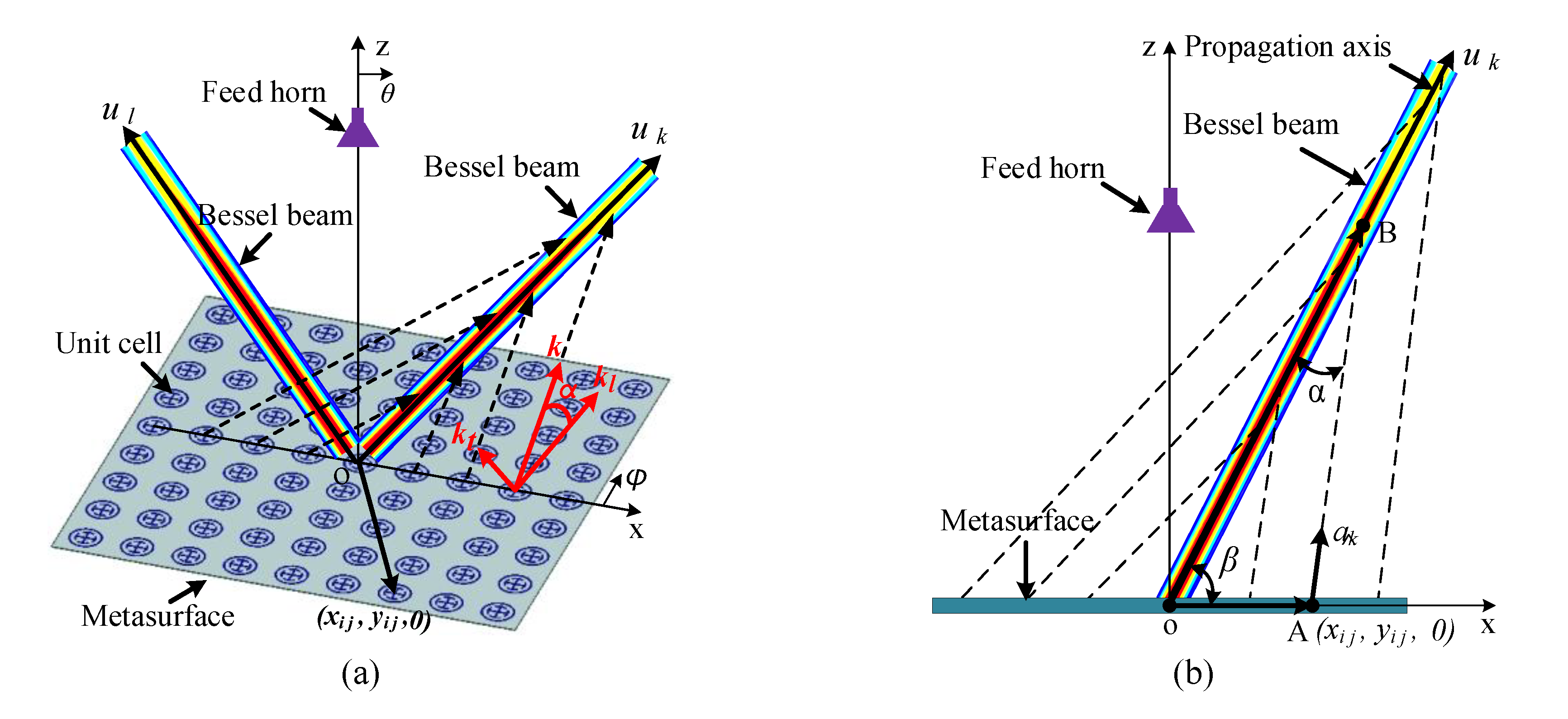
2. Design Method of the Off-Axis Pseudo Bessel Beam and Multiple Pseudo Bessel Beams

A metasurface has a controllable phase shift to realize the control of the electromagnetic wave by adjusting the unit cells. As shown in Figure 1a, the metasurface on the xoy-plane can be used to generate pseudo Bessel beams, propagating in the directions of uk or ul, which means any direction in the coordinate system. It is important to calculate the compensation phase of each unit cell whose coordinate is ( x i j , y i j , 0 ) , and the unit cell we proposed has the structure of two rings and one cross, which will be explained in detail in the next section. The compensation phase that the unit cell provides is controlled by the size of the unit cell, and the compensation phase distribution of the metasurface is decided by the beams we prepare to generate. As the generation of a pseudo Bessel beam needs the coherent superimposition of both inward conical waves and outward conical waves [13,33], it is necessary to modulate these waves by the metasurface. As shown in Figure 1a, the energy radiated from the feed horn to the metasurface can be modulated by the unit cells to form the inward conical wave. The inward conical wave is shown as dashed lines in Figure 1a,b; it is worth pointing out that all of the unit cells contribute for the inward conical wave so that they can form a conical surface. After passing through the propagation axis, the inward conical wave becomes the outward conical wave, and a pseudo Bessel beam will be formed in the overlapping area of the two. The wave vector k of the inward conical wave can be divided into the transverse component k t and the longitudinal component k l , i.e., k = k t 2 + k l 2 = 2 π / λ ( λ is the wavelength in free space). It is easy to find that if the transverse components of the inward and outward conical waves have the same magnitude and opposite directions, a standing wave will be formed in the transverse direction. In other words, the angle α between the inward conical wave and the propagation axis ( tan α = k t / k l ) remains the same in this condition, and this will prohibit the energy to leak out in the transverse direction. Meanwhile, the longitudinal components of the inward and outward conical waves will have the same magnitude and direction, so a traveling wave can be formed in the longitudinal direction. Therefore, in the superimposed region, a pseudo Bessel beam can propagate along the propagation axis with all of the electromagnetic energy.
From the mentioned generation procedure of a pseudo Bessel beam, we can know that forming a standing wave in the transverse direction is the key that all of the energy can propagate along the desired direction. This also means the included angle α between the inward conical wave and the propagation axis needs to remain the same, and as the focused beams do not meet this requirement, they cannot remain uniform in energy distribution during a long distance [26,27,28,29]. Only in this way can the “standing wave” condition be satisfied, and all of the energy can be propagated along the propagation axis without leaking to other directions. Based on the above principle and discussion, we can give a method for generating an off-axis pseudo Bessel beam using a metasurface.
As it is shown in Figure 1b, the first thing we need to do is to determine the propagation direction of the pseudo Bessel beam; the unit vector of the pseudo Bessel beam can be expressed as u ^ k = ( sin θ k cos φ k , sin θ k sin φ k , cos θ k ) , where θ k and φ k are the pitch angle and the azimuth angle of the desired beam in the coordinate system, respectively. Then we need to determine the ratio of the wave vector’s transverse component to the longitudinal component; that is, determine the angle α. Based on these settings, the required compensation phase distribution on the metasurface can be calculated according to the condition of the transverse component of the wave vector and geometric optics. This method can satisfy the condition of forming a standing wave on the plane that is perpendicular to the beam propagation direction, thereby ensuring that all energy radiates along the propagation axis.
To get the compensation phase distribution of the reflective metasurface, which can generate the energy-focused, off-axis pseudo Bessel beam, the phase of the E-field at each point on the metasurface can be expressed as
Φ 1 ( x i j , y i j ) = 2 π λ a ^ k · O A
where a ^ k is the unit vector along to the inward conical wave of each point, as shown in Figure 1b, and the vector corresponding to each point on the metasurface can be expressed as
O A = x i j 2 + y i j 2 ( cos φ i j ,   sin φ i j , 0 )
where φ i j = arctan ( y i j / x i j ) . The vector corresponding to the intersection of the straight line in the direction of any vector a ^ k and the propagation axis is
O B = sin ( 180 β α ) sin α x i j 2 + y i j 2 u ^ k
where β is the included angle between the vectors O A and O B , and it can be obtained by the vector operation
cos β = sin θ k cos φ k cos φ i j + sin θ k sin φ k sin φ i j
Finally, the unit vector a ^ k can be expressed as
a ^ k = ( O B O A ) | O B O A |
Taking Equation (5) into Equation (1), the phase Φ 1 ( x i j , y i j ) at each point of the metasurface can be calculated for the off-axis pseudo Bessel beam, which is also the compensation phase of each unit cell to transform the plane wave to the inward conical wave. However, the feed horn we actually use can only radiate the spherical wave. Therefore, we also need to calculate the compensation phase on the metasurface to convert the spherical wave radiated from the feed horn into the plane wave. The required compensation phase is
Φ 2 ( x i j , y i j ) = 2 π λ ( x i j 2 + y i j 2 + r f 2 r f )
where r f is the distance from the feed horn to the metasurface. Then, the final compensation phase of any off-axis pseudo Bessel beam generated by the feed horn and the metasurface is
Φ k ( x i j , y i j ) = Φ 1 ( x i j , y i j ) + Φ 2 ( x i j , y i j )
In this way, we can get the compensation phase of each unit cell on the metasurface to generate the k-th off-axis pseudo Bessel beam, and the compensation phase to generate multiple pseudo Bessel beams can be gotten by using the electromagnetic field superposition principle. The phase compensation of each unit cell whose coordinate is ( x i j , y i j , 0 ) can be calculated by the following equation [34]:
Φ t o t a l ( x i j , y i j ) = arg { k = 1 n exp ( j Φ k ( x i j , y i j ) ) }
where j is the imaginary unit, Φ k is the compensation phase that needed to be adjusted on the k-th beam, and n is the total number of the multiple pseudo Bessel beams.

3. Metasurface Simulation and Experimental Measurement Results

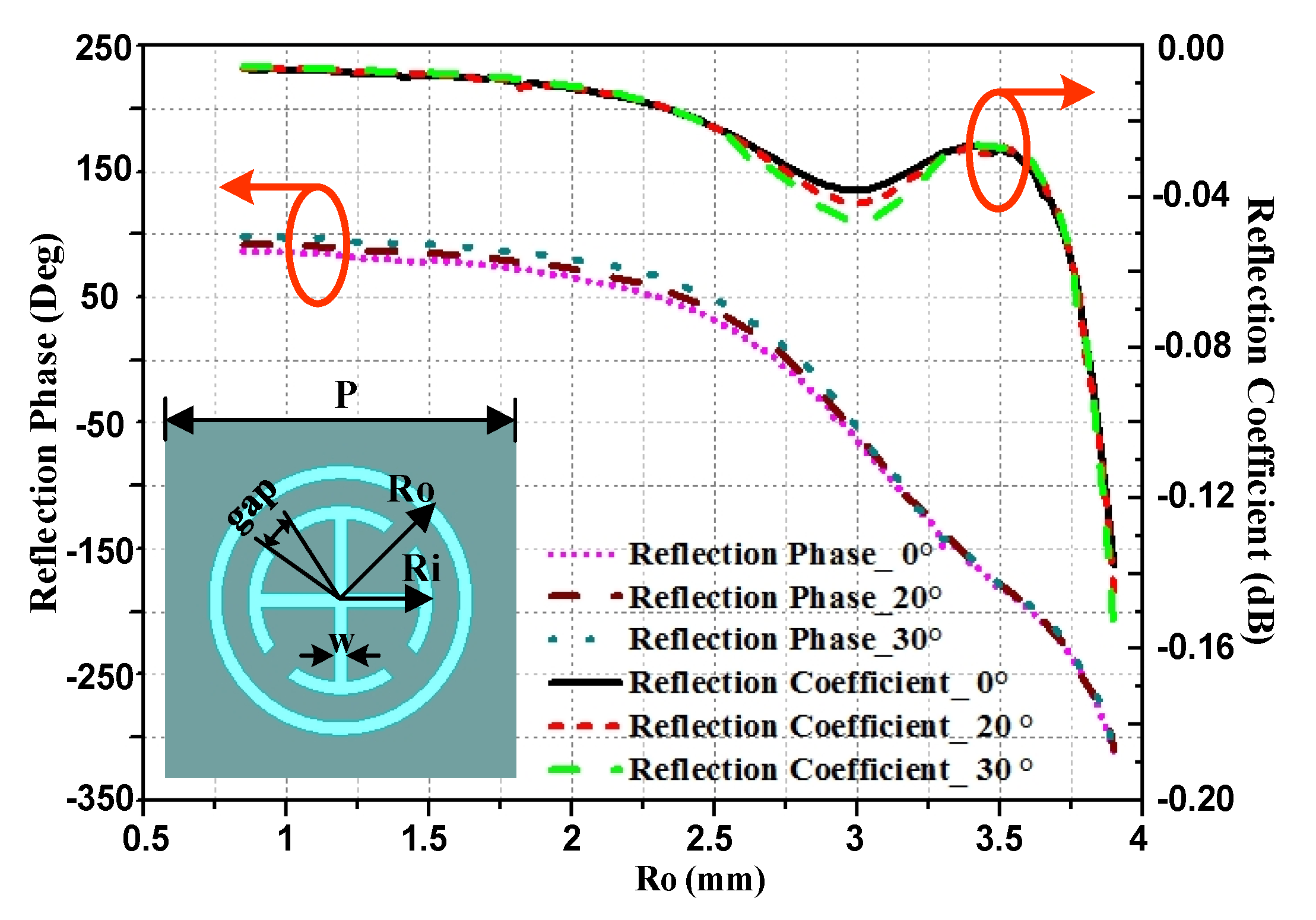
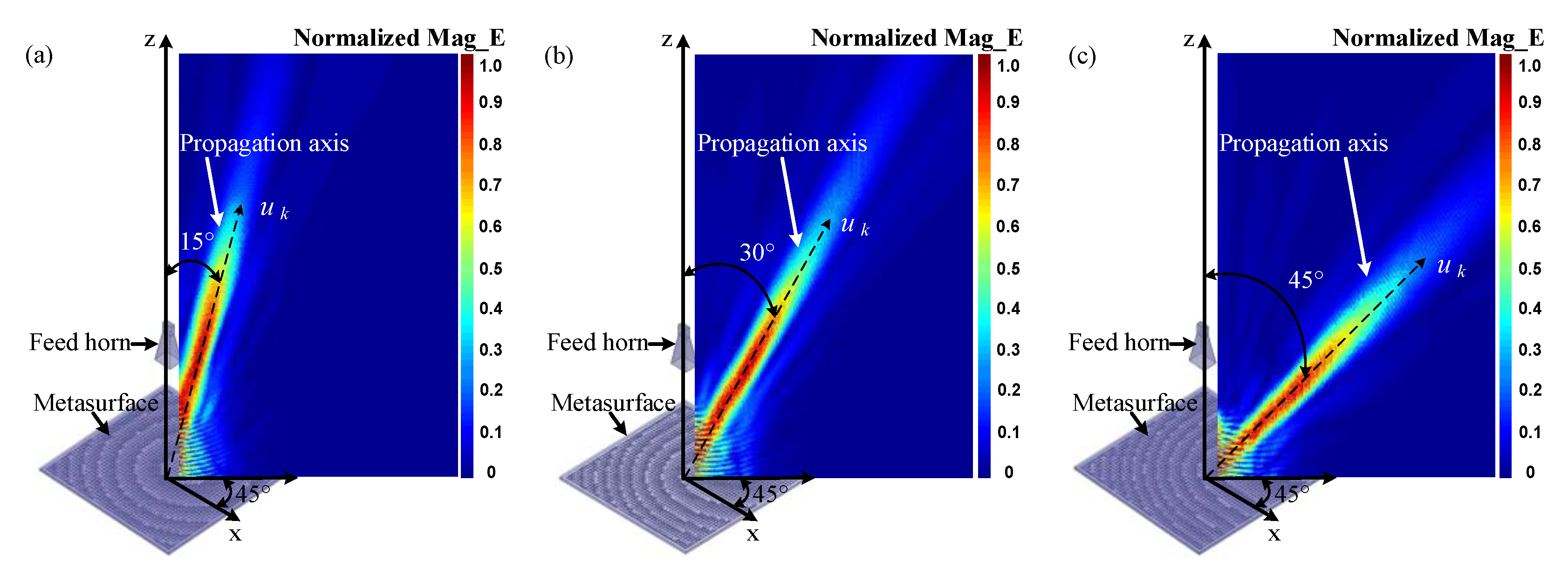
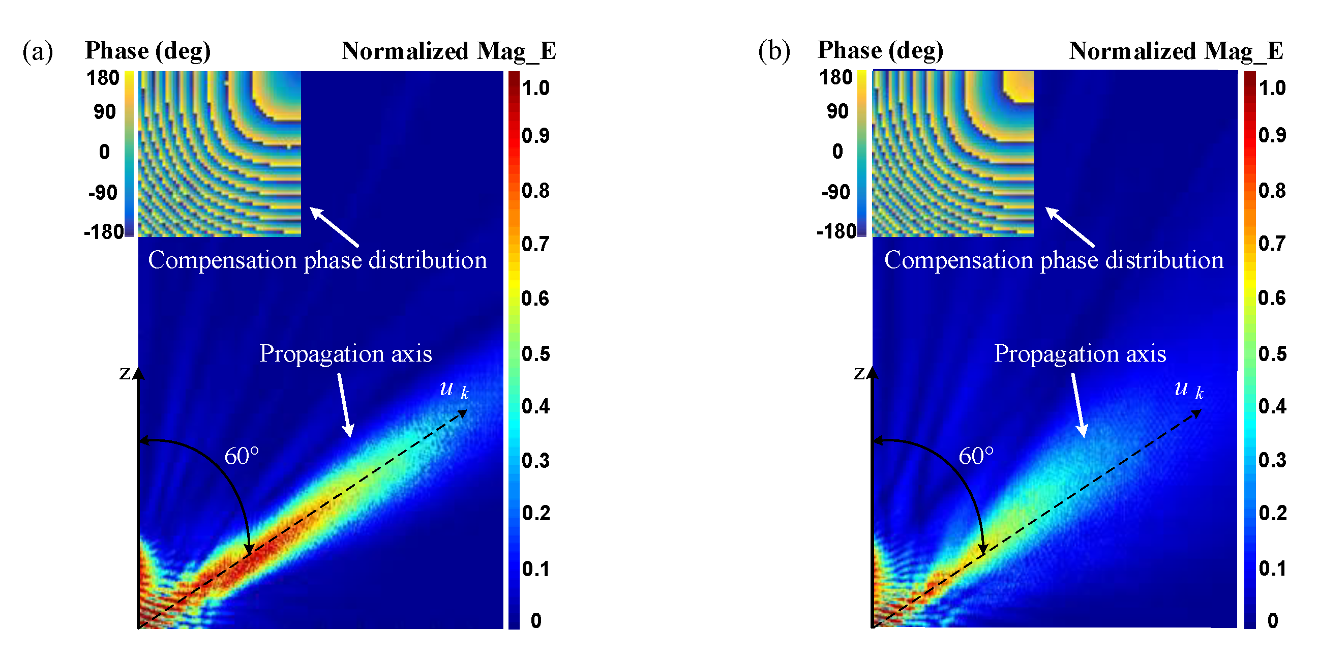
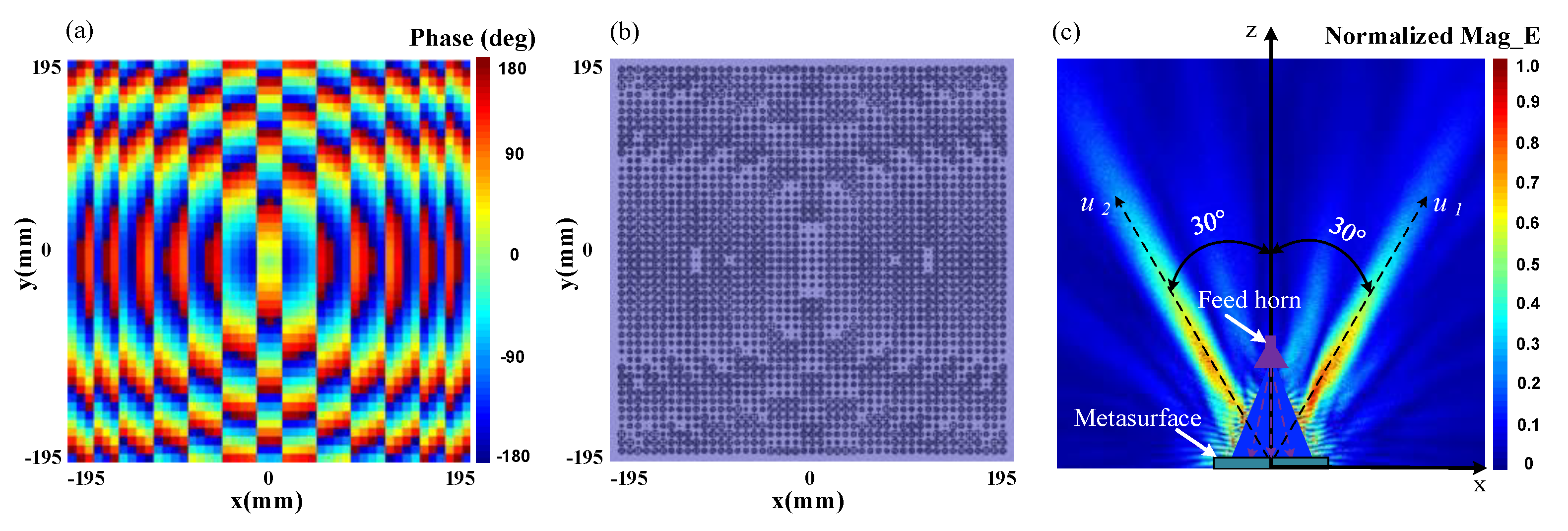
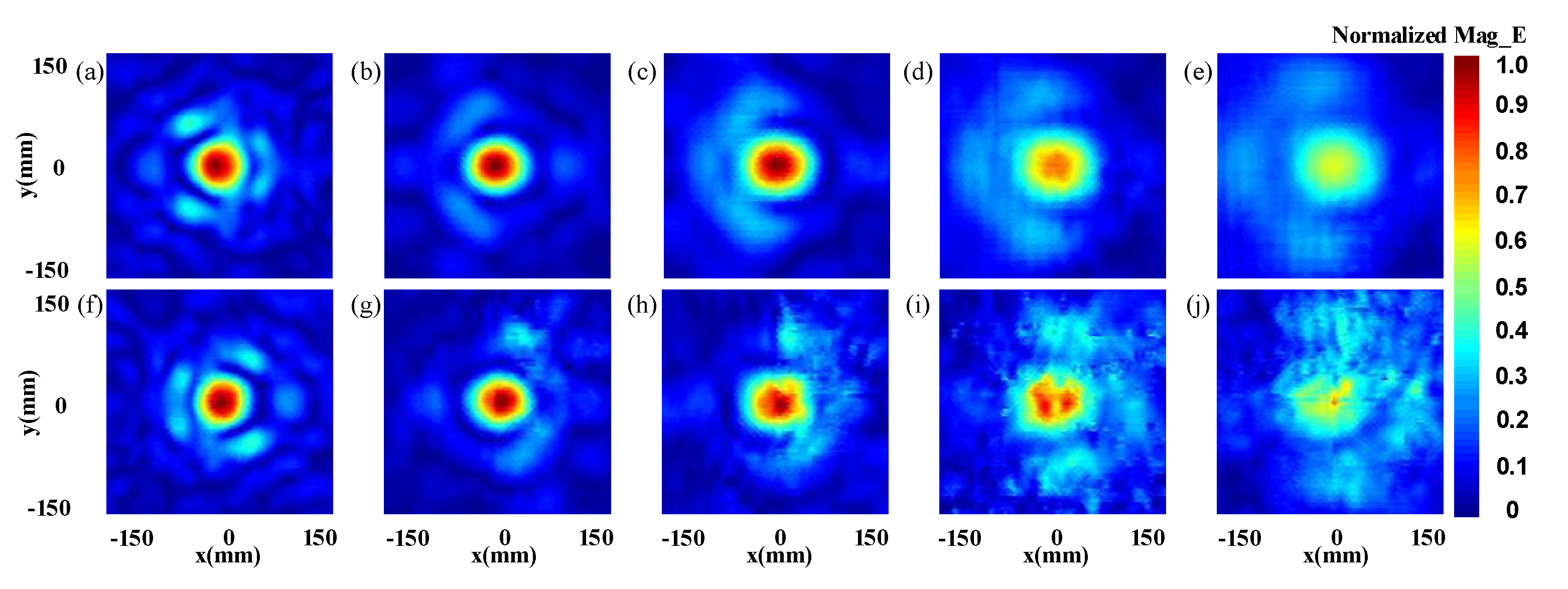
3.1. Metasurface Simulation and Results

As the method of calculating the compensation phase for generating a single off-axis pseudo Bessel beam and multiple pseudo Bessel beams by a metasurface has been proposed, we can use the suitable unit cell to compose the needed metasurfaces. A miniaturized subwavelength unit cell with a periodicity P = 8 mm (0.27 λ ) [13] is selected as the unit cell of the metasurface, as show in Figure 2. The unit cell comprises two concentric circular rings, while the inner ring is connected to a cross, and is also separated by four identical gaps with an angle of 20°. The radiuses of the outer ring and the inner ring are Ro and Ri, which has the relationship of R i = 0.7 × R o , and the width of both the rings and the cross is w = 0.3 mm. This unit cell is printed on a F4B ( ε r = 2.65 ) dielectric substrate with a thickness of t = 3 mm, and the model of it is built in the simulation software ANSYS HFSS, with periodic boundary conditions. The reflection phase and reflection coefficient characteristics of the unit cell versus the length of Ro at the center frequency of 10 GHz are shown in Figure 2.
As shown in Figure 2, by varying Ro from 0.85 to 3.9 mm, the reflection phase variation range of the unit cell can cover the whole 360°, and it can be seen that the phase-shift changes are less than 17° when the incidence angle varies from 0° to 30°. Meanwhile, the reflection coefficient keeps above −0.2 dB when the incidence angle varies, so that this miniaturized unit cell has the characteristics of both high efficiency and good angle stability; it is also polarization-insensitive because of its symmetrical structure.
According to the method mentioned and the relationship between the unit cell size and its reflection phase curves shown in Figure 2, the metasurfaces to generate off-axis pseudo Bessel beams can be designed. All of the metasurfaces have a size of 390 mm × 390 mm, and the distance from the feed horn to the metasurfaces is 300 mm. The azimuth angle of the beam is set to be φ k = 45 ° , and the angle between the inward conical wave and the propagation axis is α = 10 ° . In order to show the universality of this method, we chose the pitch angles to be 15°, 30°, and 45°, respectively. The designed metasurfaces were simulated by ANSYS HFSS, and the models and simulated results of the generated off-axis pseudo Bessel beams are shown in Figure 3.
The normalized E-field amplitude distributions in Figure 3 show that the off-axis pseudo Bessel beams, which have the predetermined orientations, were generated successfully. As the energy is concentrated along the propagation axis without leakage in other directions, the method we use shows its effectiveness. To demonstrate the superiority of the proposed method, we can compare it with the traditional method, which realizes the off-axis pseudo Bessel beam by adding the compensation phases of the on-axis Bessel beam and the deflected beam. As the differences between these two methods will become more obvious when the pitch angle becomes larger, we set the pitch angle to be 60°, and the other settings are just the same as in Figure 3. The normalized E-field amplitude distributions and corresponding compensation phase distributions of the off-axis pseudo Bessel beams using the two different methods are shown in Figure 4.
It is easy to find that the compensation phase distributions of the two methods have the same trend, but the difference is also obvious. The simulated results show that the pseudo Bessel beam using the proposed method can keep the energy concentrating on the propagation axis in the non-diffraction area, while the divergence of energy is obvious in the traditional method. So compared with previous methods, the proposed method shows its superiority.
Based on the high-performance, off-axis pseudo Bessel beams we have generated, and the superposition of different off-axis pseudo Bessel beams according to Equation (8), multiple pseudo Bessel beams can also be generated simultaneously using the metasurface. We chose the dual pseudo Bessel beams as an example, and the propagation directions were set to be θ 1 = 30 ° ,   φ 1 = 0 ° and θ 2 = 30 ° ,   φ 2 = 180 ° , respectively, while the angle α = 10 ° for both of the two beams. The unit cell was still chosen to be the unit cell shown in Figure 2, and the metasurface has the whole dimension of 390 mm × 390 mm × 3 mm, while the coordinate of the feed horn in the coordinate system was still 0 mm, 0 mm, and 300 mm. Then, the required compensation phase distribution, the layout of the metasurface, and the simulated normalized E-field amplitude distribution of the generated dual pseudo Bessel beams on the xoz-plane are shown in Figure 5.
It can be seen from Figure 5c that the dual pseudo Bessel beams have been generated by the metasurface simultaneously, and the propagation directions of them meet the predetermined settings. The energy is also concentrated along the propagation axes, and to further prove this, we can observe the normalized E-field amplitude distributions on two sets of observation planes that are, respectively, perpendicular to the two propagation directions. These observation planes with a size of 0.3 m × 0.3 m are placed at different distances from the metasurface, and the distances are 400 mm, 600 mm, 800 mm, 1000 mm, and 1200 mm, respectively.
As shown in Figure 6, it is obvious that the energy is concentrated on the center point of each observation plane, which is also the intersection of the propagation axis and the observation plane. In addition, the normalized E-field amplitudes of both the two beams decrease as the distances from the metasurface increase, while the normalized E-field amplitude distributions that on the same distance of the two beams are symmetrical. This phenomenon shows that the energy allocated to the two beams is basically the same, which is in line with our design.

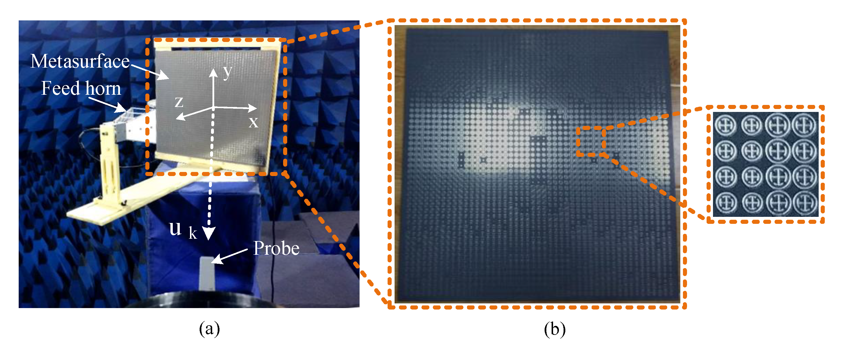
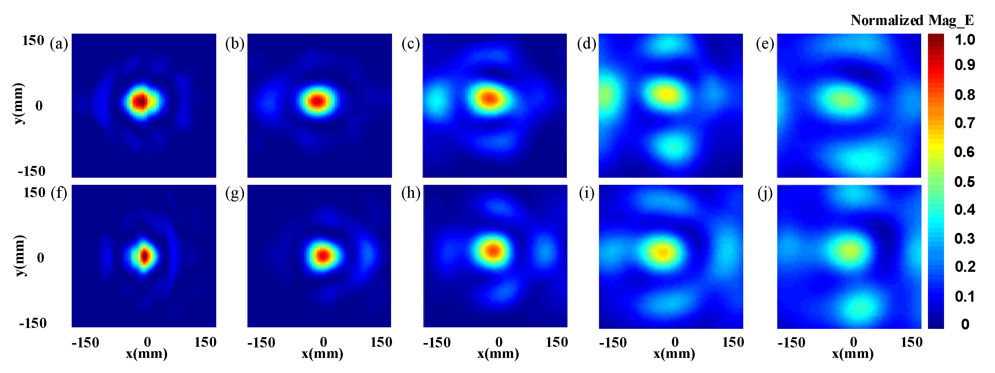
3.2. Metasurface Experimental Measurement and Results

The fabricated metasurface is fed by a broadband horn antenna that operates from 2 to 18 GHz and is measured by using the near-filed planar-scanning techniques in the anechoic chamber, as shown in Figure 7a. And the prototype of the fabricated reflective metasurface is shown in Figure 7b.
A standard waveguide probe is used to detect the normalized E-field amplitude distributions corresponding to that shown in Figure 6. To detect the off-axis beams, the metasurface should have an inclined angle of ±30° to the z-axis, and the scanning plane has a size of 0.3 m × 0.3 m with a sampling grid of 5 mm. The normalized E-field amplitude distributions on the different observation planes are, respectively, perpendicular to the two propagation directions and have a distance from the metasurface of 400 mm, 600 mm, 800 mm, 1000 mm, and 1200 mm, measured as shown in Figure 8. The comparison between Figure 6 and Figure 8 shows that the experimental measurement results of the dual pseudo Bessel beams are in good agreement with the simulated one.
In order to show the phenomenon of dual pseudo Bessel beams, we observe the normalized E-field amplitude distributions of the dual-beams on a 1.2 m × 0.6 m observation plane, which is perpendicular to the probe. The distance between the probe and the observation plane is 0.6 m, and the experimental measurement normalized E-field amplitude distribution on the observation plane is shown in Figure 9.
From the experimental measurement result shown in Figure 9, it is sure that the energy concentrates on the points where the pseudo Bessel beams pass through, and the amplitudes of the two beams are basically equivalent. So, we can draw the conclusion that the dual pseudo Bessel beams were generated by the metasurface, and almost all of the energy is propagating along the desired directions.

4. Discussion

The dual pseudo Bessel beams were generated using the designed metasurface with the proposed method. From the simulated normalized E-field amplitude distribution, we can see two pseudo Bessel beams propagate along the directions of θ 1 = 30 ° ,   φ 1 = 0 ° and θ 2 = 30 ° ,   φ 2 = 180 ° simultaneously, and the energy is divided into two almost equal parts along the desired directions. The energy along the propagation axes is nearly remaining stable, while the simulated and experimental measurement normalized E-field amplitudes at the different distances have the tendency of decreasing gradually, which means the energy is attenuating when propagating. We can calculate the transmission efficiency of the dual pseudo Bessel beams generated by the metasurface at different transmission distances to further research the energy distribution of the dual pseudo Bessel beams. As shown in Figure 10, the transmission efficiency (η) of the metasurface can be defined as the ratio of the pseudo Bessel beam power (P1) to the total power (P0) radiated by the metasurface, i.e., η = P1/P0, and the values of both P0 and P1 are the flux integral of the Poynting vector.
As the beams we generate are the dual pseudo Bessel beams, it is necessary to add the power of the two beams obtained at the same transmission distance. Here we use five different reference planes to calculate the power of the dual beams at different transmission distances. The distances from the metasurface are the same as that of the E-field observation planes mentioned, so the transmission distances are 400 mm, 600 mm, 800 mm, 1000 mm, and 1200 mm, respectively. The result shows that on the reference plane has a distance of 400 mm, and the total calculated power value of the two beams is 0.474. As the power value P0 on the metasurface can be obtained as 0.8 by integration, so the efficiency of the dual pseudo Bessel beams at 400 mm is about 59.2%. The efficiency at the latter distances was also calculated by the same method as being 36.8%, 32.6%, 27%, and 25%, respectively. It can be seen that the efficiency changes with the change in transmission distance, and it maintains a relatively high value considering that the reference planes are far away from the metasurface; that is, a high efficiency can be obtained at different transmission distances in accurately controllable propagating directions when using the proposed method to generate pseudo Bessel beams. As the energy can be allocated in multiple directions, devices at multiple different locations can be charged simultaneously. Furthermore, because the generated pseudo Bessel beams have uniform energy distributions within a certain range, the location requirements for the devices are also reduced.

5. Conclusions

In this paper, multiple pseudo Bessel beams can be effectively generated based on the method of generating an off-axis pseudo Bessel beam and the principle of superposition, and the beams have the advantages of both accurately controllable propagating directions and high efficiency. The metasurface for generating dual pseudo Bessel beams was designed, fabricated, and measured, and the simulated and experimentally measured normalized E-field distributions demonstrate that nearly all the radiated energy from the metasurface propagates along the designed directions. The full wave simulation results show that the dual beams have a high efficiency of 59.2% at a transmission distance of 400 mm from the metasurface, and the efficiency keeps relatively high in the non-diffracting area. The proposed method and device for generating multiple pseudo Bessel beams can be applied to multi-user WPT systems, wireless communication systems, and multi-objects radio frequency identification (RFID) systems with a large operating distance.

Author Contributions

H.L. and H.X. conceived the simulations and finished the paper writing; Y.L. analyzed the metasurface and performed the experiments; L.L. provided the main instructions of the ideas. All authors have read and agreed to the published version of the manuscript.

Funding

This work is supported by the Science and Technology Project of State Grid Corporation of China “Research on Ten-Meter Level Microwave Radio Wireless Power Transmission Technology”.

Conflicts of Interest

The authors declare no conflict of interest.

References

  1. Durnin, J. Exact solutions for nondiffracting beams. I. The scalar theory. J. Opt. Soc. 1987, 4, 651–654. [Google Scholar] [CrossRef]
  2. Durnin, J.; Miceli, J., Jr.; Eberly, J.H. Diffraction-free beams. Phys. Rev. Lett. 1987, 58, 1499–1501. [Google Scholar] [CrossRef] [PubMed]
  3. Ettorre, M.; Pavone, S.C.; Casaletti, M.; Albani, M. Experimental Validation of Bessel Beam Generation Using an Inward Hankel Aperture Distribution. IEEE Trans. Antennas Propag. 2015, 63, 2539–2544. [Google Scholar] [CrossRef] [Green Version]
  4. Ettorre, M.; Rudolph, S.M.; Grbic, A. Generation of Propagating Bessel Beams Using Leaky-Wave Modes. IEEE Trans. Antennas Propag. 2012, 60, 3605–3613. [Google Scholar] [CrossRef]
  5. Monk, S.; Arlt, J.; Robertson, D.A.; Courtial, J.; Padgett, M.J. The generation of Bessel beams at millimetre-wave frequencies by use of an axicon. Opt. Commun. 1999, 170, 213–215. [Google Scholar] [CrossRef]
  6. Li, Y.B.; Cai, B.G.; Wan, X.; Cui, T.J. Diffraction-free surface waves by metasurfaces. Opt. Lett. 2014, 39, 5888–5891. [Google Scholar] [CrossRef]
  7. Mazzinghi, A.; Balma, M.; Devona, D.; Guarnieri, G.; Mauriello, G.; Albani, M.; Freni, A. Large depth of field pseudo-Bessel beam generation with a RLSA antenna. IEEE Trans. Antenna Propag. 2014, 62, 3911–3919. [Google Scholar] [CrossRef]
  8. Rodriguez, E.S.G.; Machnoor, M.; Lazzi, G. On the generation of nondiffracting beams in extremely subwavelength applications. IEEE Trans. Antennas Propag. 2017, 65, 5228–5237. [Google Scholar] [CrossRef]
  9. Heebl, J.D.; Ettorre, M.; Grbic, A. Wireless links in the radiative near field via Bessel beams. Phys. Rev. Appl. 2016, 6, 034018. [Google Scholar] [CrossRef]
  10. Imani, M.F.; Grbic, A. Generating Evanescent Bessel Beams Using Near-Field Plates. IEEE Trans. Antennas Propag. 2012, 60, 3155–3164. [Google Scholar] [CrossRef]
  11. Kou, N.; Yu, S.; Li, L. Generation of high-order Bessel vortex beam carrying orbital angular momentum using multilayer amplitude-phase-modulated surfaces in radiofrequency domain. Appl. Phys. Express 2016, 10, 016701. [Google Scholar] [CrossRef]
  12. Pfeiffer, C.; Grbic, A. Controlling Vector Bessel Beams with Metasurfaces. Phys. Rev. Appl. 2014, 2, 044012. [Google Scholar] [CrossRef]
  13. Liu, H.; Xue, H.; Liu, Y.; Feng, Q.; Li, L. Generation of high-order Bessel orbital angular momentum vortex beam using a single-layer reflective metasurface. IEEE Access 2020, 8, 126504–126510. [Google Scholar] [CrossRef]
  14. Lemaitre-Auger, P.; Abielmona, S.; Caloz, C. Generation of Bessel Beams by Two-Dimensional Antenna Arrays Using Sub-Sampled Distributions. IEEE Trans. Antennas Propag. 2013, 61, 1838–1849. [Google Scholar] [CrossRef]
  15. Mei, Q.Q.; Wen, X.T.; Cui, T.J. A Broadband Bessel Beam Launcher Using Metamaterial Lens. Sci. Rep. 2015, 5, 11732. [Google Scholar]
  16. Salem, M.A.; Kamel, A.H.; Niver, E. Microwave Bessel Beams Generation Using Guided Modes. IEEE Trans. Antennas Propag. 2011, 59, 2241–2247. [Google Scholar] [CrossRef]
  17. Trappe, N.; Mahon, R.; Lanigan, W.; Murphy, J.A.; Withington, S. The quasi-optical analysis of Bessel beams in the far infrared. Infrared Phys. Technol. 2005, 46, 233–247. [Google Scholar] [CrossRef] [Green Version]
  18. Vasara, A.; Friberg, A.T.; Turunen, J. Holographic generation of diffraction-free beams. Appl. Opt. 1988, 27, 3959. [Google Scholar]
  19. Yi, C.Z.; Yu, J.C. Ka-Band Wideband Large Depth-of-Field Beam Generation through a Phase Shifting Surface Antenna. IEEE Trans. Antennas Propag. 2016, 64, 5038–5045. [Google Scholar]
  20. Zhaofeng, L.; Boratay, A.K.; Humeyra, C.; Ekmel, O. Generation of an axially asymmetric Bessel-like beam from a metallic subwavelength aperture. Phys. Rev. Lett. 2009, 102, 143901. [Google Scholar]
  21. Wei, T.C.; Khorasaninejad, M.; Zhu, A.Y.; Oh, J.; Devlin, R.C.; Zaidi, A.; Capasso, F. Generation of wavelength-independent subwavelength Bessel beams using metasurfaces. Light Sci. Appl. 2016, 6, e16259. [Google Scholar]
  22. Salo, J.; Meltaus, J.; Noponen, E.; Westerholm, J.; Salomaa, M.M.; Lonnvist, A.; Saily, J.; Hakli, J.; Ala-Laurinaho, J.; Raisanen, A.V. Millimetre-wave Bessel beams using computer holograms. Electron. Lett. 2002, 37, 834–835. [Google Scholar] [CrossRef] [Green Version]
  23. Yi, C.Z.; Yu, J.C. Wideband Quasi-Non-Diffraction Beam with Accurately Controllable Propagating Angle and Depth-of-Field. IEEE Trans. Antennas Propag. 2017, 65, 5035–5042. [Google Scholar]
  24. Cheng, Y.; Zhong, Y.; Renbo, H.E.; Liu, Y.; Fan, Y.; Song, K.; Zhang, Y. Antenna for Generating Arbitrarily Directed Bessel Beam. U.S. Patent No. 10,644,398, 5 May 2020. [Google Scholar]
  25. Wu, Y.; Cheng, Y. Generating and 2-D Steering Large Depth-of-Field Beam by Leaky-Wave Antenna Array with a Modified Parabolic Reflector. IEEE Trans. Antennas Propag. 2019, 68, 2779–2787. [Google Scholar] [CrossRef]
  26. Wu, Y.; Cheng, Y.; Huang, Z. Ka-band near-field-focused 2-D steering antenna array with a focused Rotman lens. IEEE Transactions on Antennas and Propagation. IEEE Trans. Antennas Propag. 2018, 66, 5204–5213. [Google Scholar] [CrossRef]
  27. Buffi, A.; Nepa, P.; Manara, G. Design criteria for near-field-focused planar arrays. IEEE Antennas Propag. Mag. 2012, 54, 40–50. [Google Scholar] [CrossRef]
  28. Álvarez, J.; Ayestarán, R.G.; León, G.; Herrán, L.F.; Arboleya, A.; López-Fernández, J.A.; Las-Heras, F. Near field multifocusing on antenna arrays via non-convex optimisation. IET Microw. Antennas Propag. 2014, 8, 754–764. [Google Scholar] [CrossRef]
  29. Ettorre, M.; Pavone, S.C.; Casaletti, M.; Albani, M.; Mazzinghi, A.; Freni, A. Near-field focusing by non-diffracting Bessel beams. In Aperture Antennas for Millimeter and Sub-Millimeter Wave Applications, Signals and Communication Technology; Springer: Rennes, France, 2018; Volume 8, pp. 243–288. [Google Scholar]
  30. Shaltout, A.M.; Kildishev, A.V.; Shalaev, V.M. Evolution of photonic metasurfaces: From static to dynamic. J. Opt. Soc. Am. B 2016, 33, 501–510. [Google Scholar] [CrossRef]
  31. Li, L.; Liu, H.; Zhang, H.; Xue, W. Efficient wireless power transfer system integrating with metasurface for biological applications. IEEE Trans. Ind. Electron. 2018, 65, 3230–3239. [Google Scholar] [CrossRef]
  32. Li, L.; Zhang, X.; Song, C.; Huang, Y. Progress, challenges, and perspective on metasurfaces for ambient radio frequency energy harvesting. Appl. Phys. Lett. 2020, 116, 060501. [Google Scholar] [CrossRef]
  33. Chávez-Cerda, S. A new approach to Bessel beams. J. Mod. Opt. 1999, 46, 923–930. [Google Scholar] [CrossRef]
  34. Yu, S.; Li, L.; Shi, G.; Zhu, C.; Shi, Y. Generating multiple orbital angular momentum vortex beams using a metasurface in radio frequency domain. Appl. Phys. Lett. 2016, 108, 241901. [Google Scholar] [CrossRef]
Figure 1. Schematic diagram of (a) pseudo Bessel beams generated by a reflective metasurface; (b) the proposed method to generate the off-axis pseudo Bessel beam.
Applsci 10 07219 g001
Figure 2. Geometry (top view) of the designed unit cell and the reflection phase and reflection coefficient versus the length of Ro in an infinite periodic model with different incidence angles.
Applsci 10 07219 g002
Figure 3. The normalized E-field amplitude distributions of the off-axis pseudo Bessel beams with the propagation directions of (a) θ k = 15 ° ,   φ k = 45 ° ; (b) θ k = 30 ° ,   φ k = 45 ° ; (c) θ k = 45 ° ,   φ k = 45 ° .
Applsci 10 07219 g003
Figure 4. The normalized E-field amplitude distributions of the off-axis pseudo Bessel beams and their corresponding compensation phase distributions when using (a) the proposed method; (b) the traditional method.
Applsci 10 07219 g004
Figure 5. (a) The compensation phase distribution of the designed metasurface; (b) the layout of the metasurface; (c) the normalized E-field amplitude distribution of the dual pseudo Bessel beams on the xoz-plane.
Applsci 10 07219 g005
Figure 6. Simulated normalized E-field amplitude distributions on the different observation planes at the distances of (a) 400 mm, (b) 600 mm, (c) 800 mm, (d) 1000 mm, and (e) 1200 mm away from the metasurface when the azimuth angle of the pseudo Bessel beam is 0°. The simulated normalized E-field amplitude distributions on the different observation planes at the distances of (f) 400 mm, (g) 600 mm, (h) 800 mm, (i) 1000 mm, and (j) 1200 mm away from the metasurface when the azimuth angle of the pseudo Bessel beam is 180°.
Applsci 10 07219 g006
Figure 7. (a) Experimental measurement scene of the dual pseudo Bessel beams in the anechoic chamber; (b) the prototype of the fabricated reflective metasurface.
Applsci 10 07219 g007
Figure 8. Experimental measurement normalized E-field amplitude distributions on the different observation planes at a distance of (a) 400 mm, (b) 600 mm, (c) 800 mm, (d) 1000 mm, and (e) 1200 mm away from the metasurface when the azimuth angle of the pseudo Bessel beam is 0°. The experimental measurement normalized E-field amplitude distributions on the different observation planes at a distance of (f) 400 mm, (g) 600 mm, (h) 800 mm, (i) 1000 mm, and (j) 1200 mm away from the metasurface when the azimuth angle of the pseudo Bessel beam is 180°.
Applsci 10 07219 g008
Figure 9. Experimental measurement normalized E-field amplitude distribution of the dual pseudo Bessel beams on the observation plane with a size of 1.2 m × 0.6 m and a distance to the probe of 0.6 m.
Applsci 10 07219 g009
Figure 10. Schematic diagram of the efficiency calculation method.
Applsci 10 07219 g010
Publisher’s Note: MDPI stays neutral with regard to jurisdictional claims in published maps and institutional affiliations.

