Robocasting of Single and Multi-Functional Calcium Phosphate Scaffolds and Its Hybridization with Conventional Techniques: Design, Fabrication and Characterization

 , , ,
, , ,
Abstract
:Featured Application
Abstract
1. Introduction
2. Materials and Methods
2.1. Robocasting
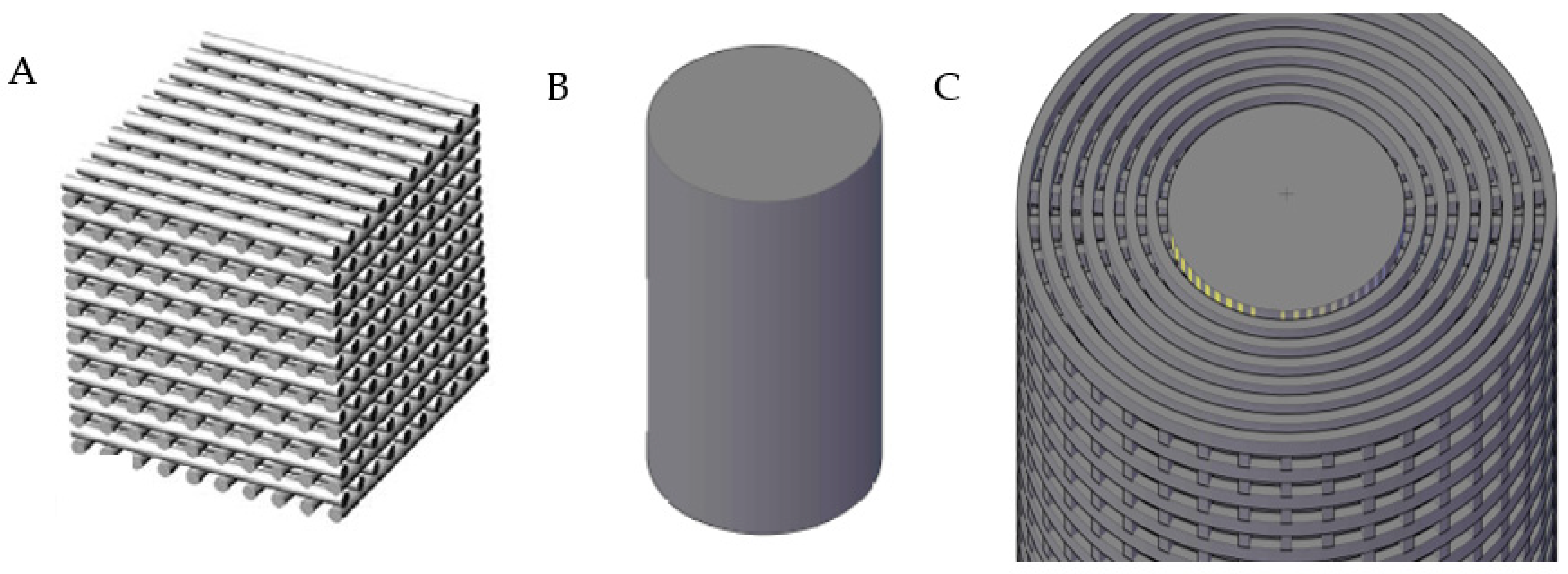
2.1.1. Design of CAD Models
2.1.2. Materials
2.1.3. Scaffolds Fabrication
2.1.4. Scaffolds Characterizations
2.2. Hybrid Technologies: Robocasting Joined with Polymer Processing Routes
2.2.1. Fabrication of Hybrid Ceramic-Polymer Scaffolds
2.2.2. In-Vitro Bacterial Adhesion Assay
3. Results and Discussions
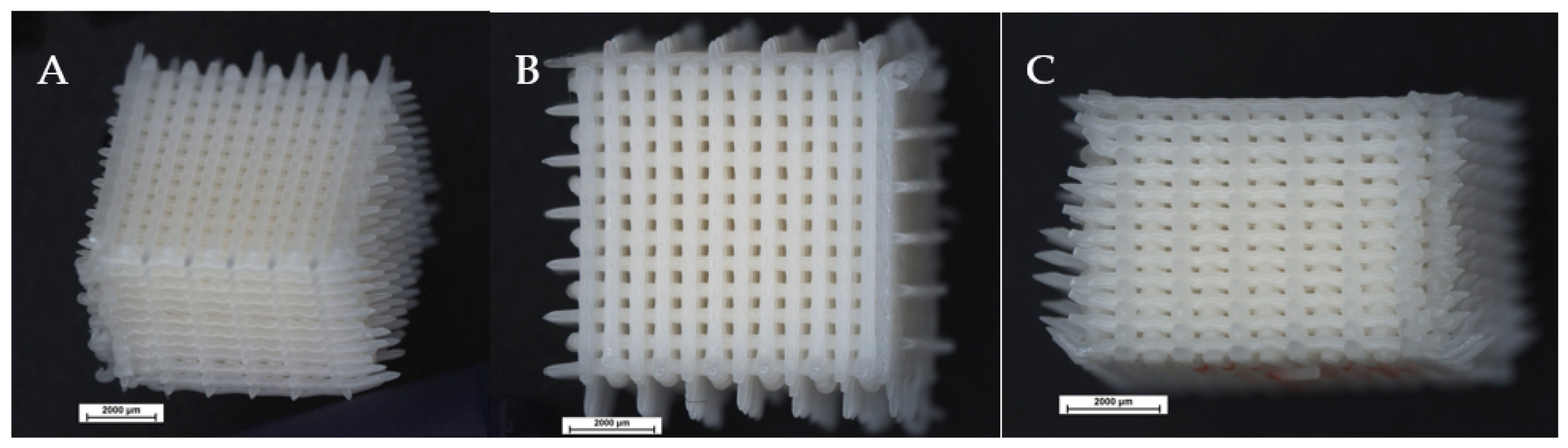
3.1. Robocasting of Lattice, Dense and Bi-Layer Parts
3.1.1. Paste Formulations
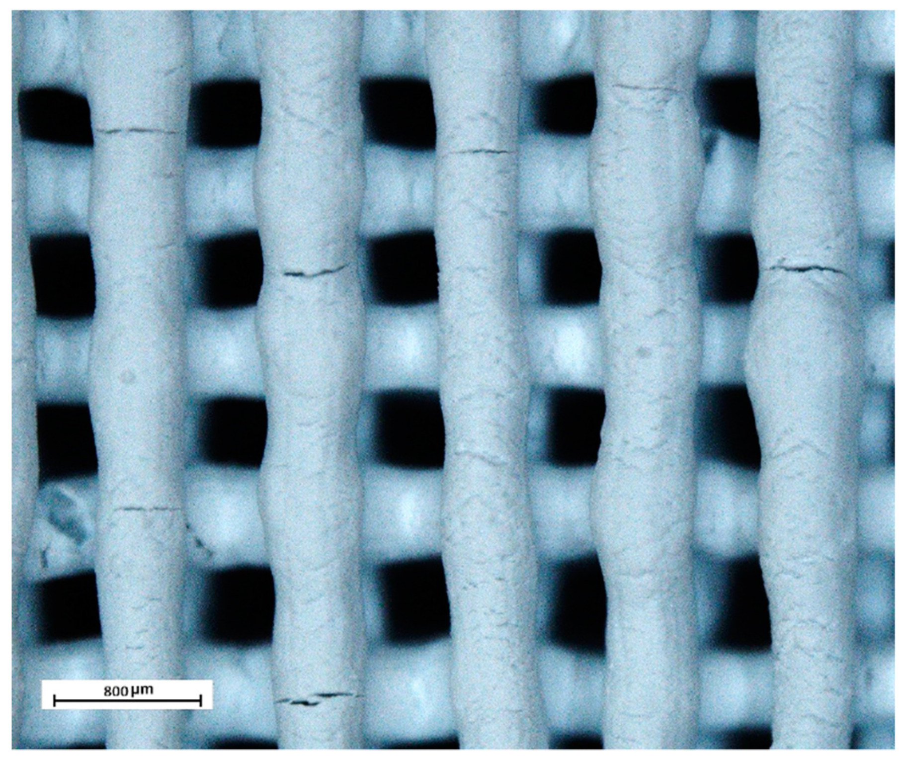
3.1.2. Porous Parts
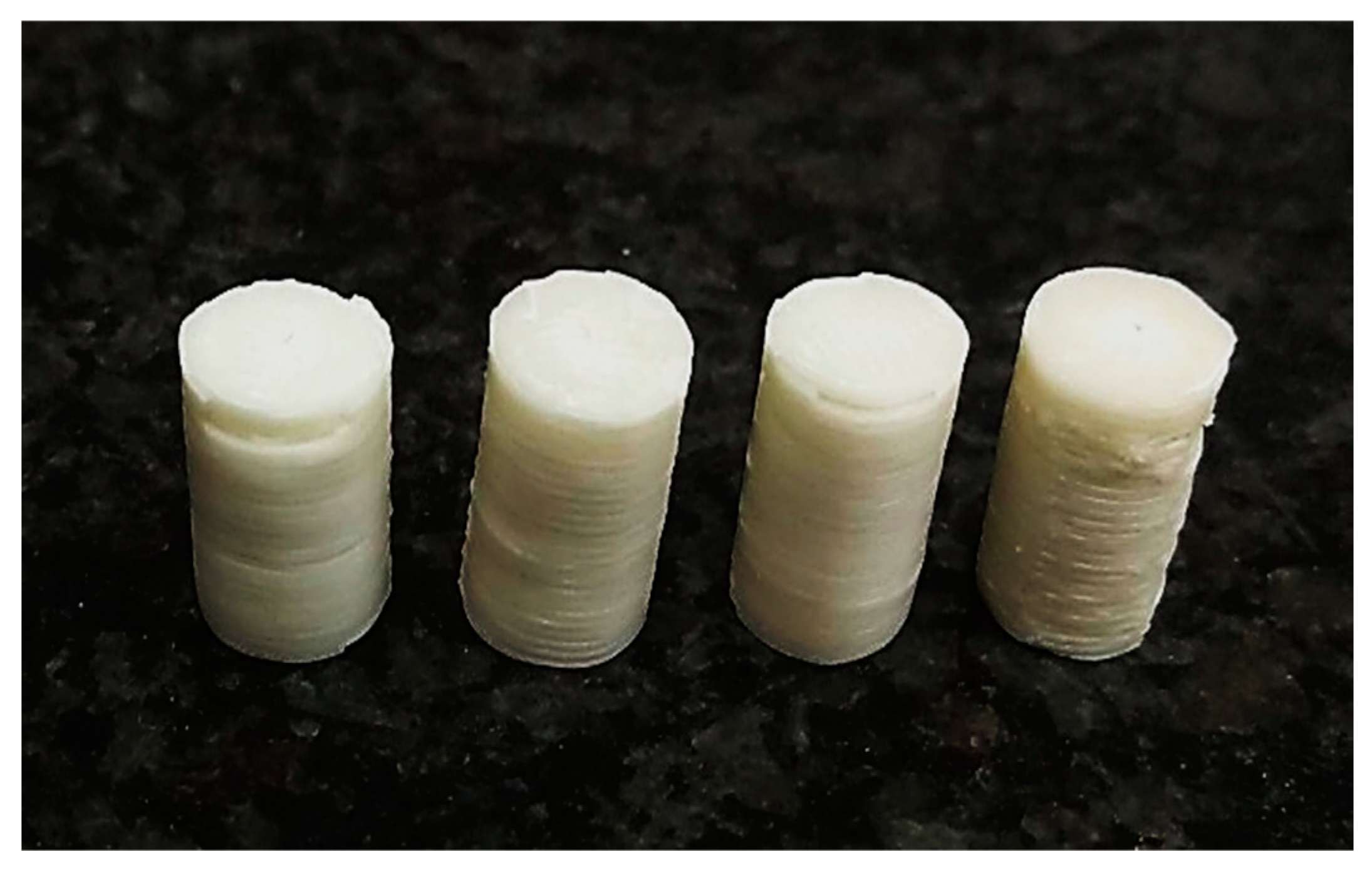
3.1.3. Dense Parts
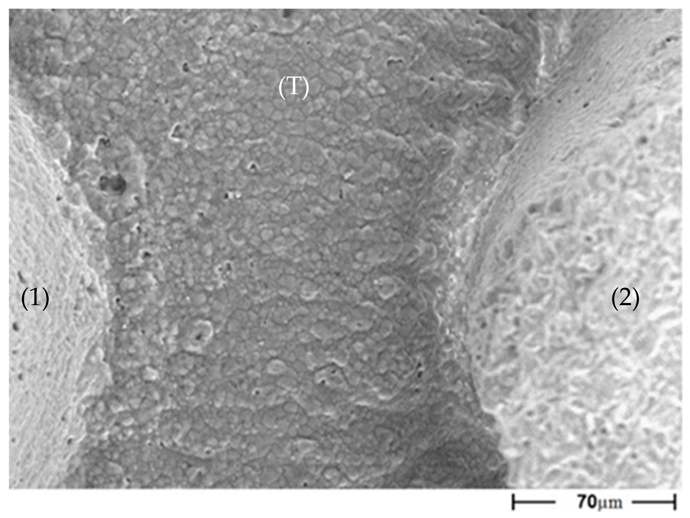
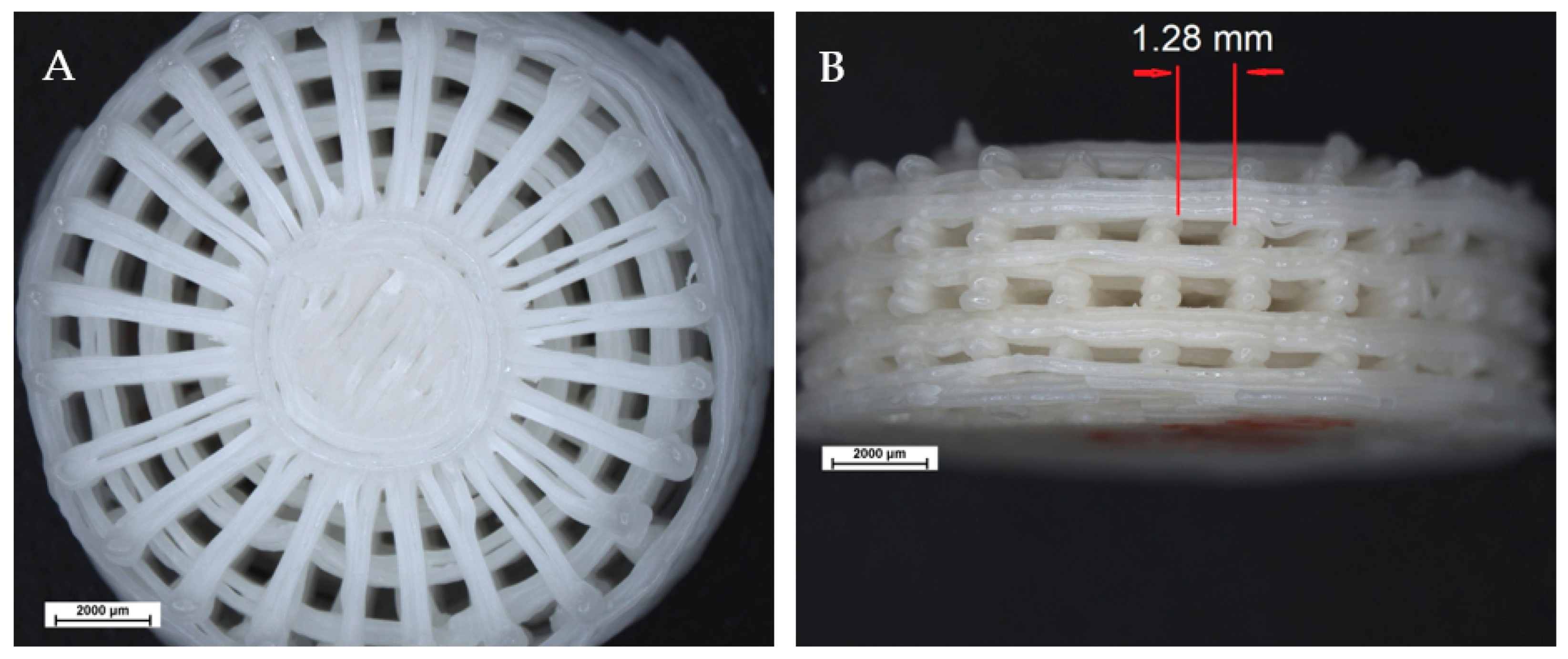
3.1.4. FGM Bi-Layer Parts
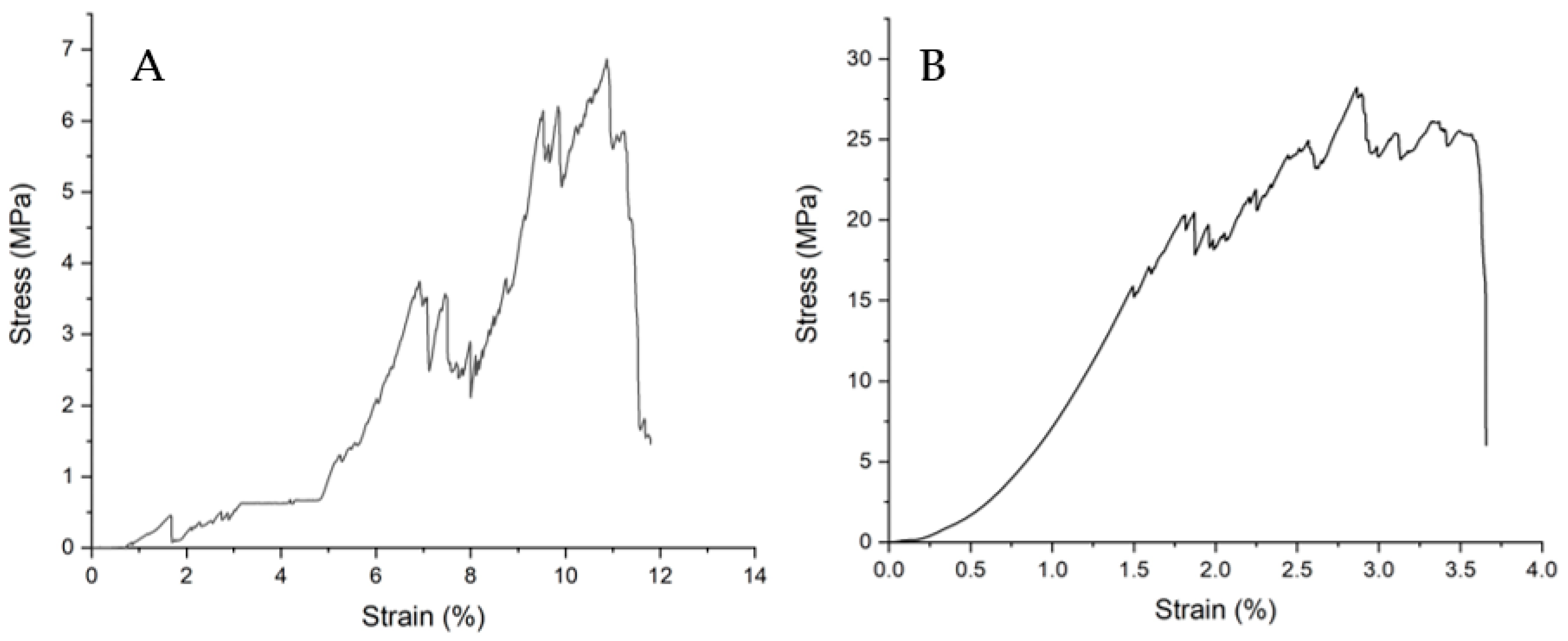
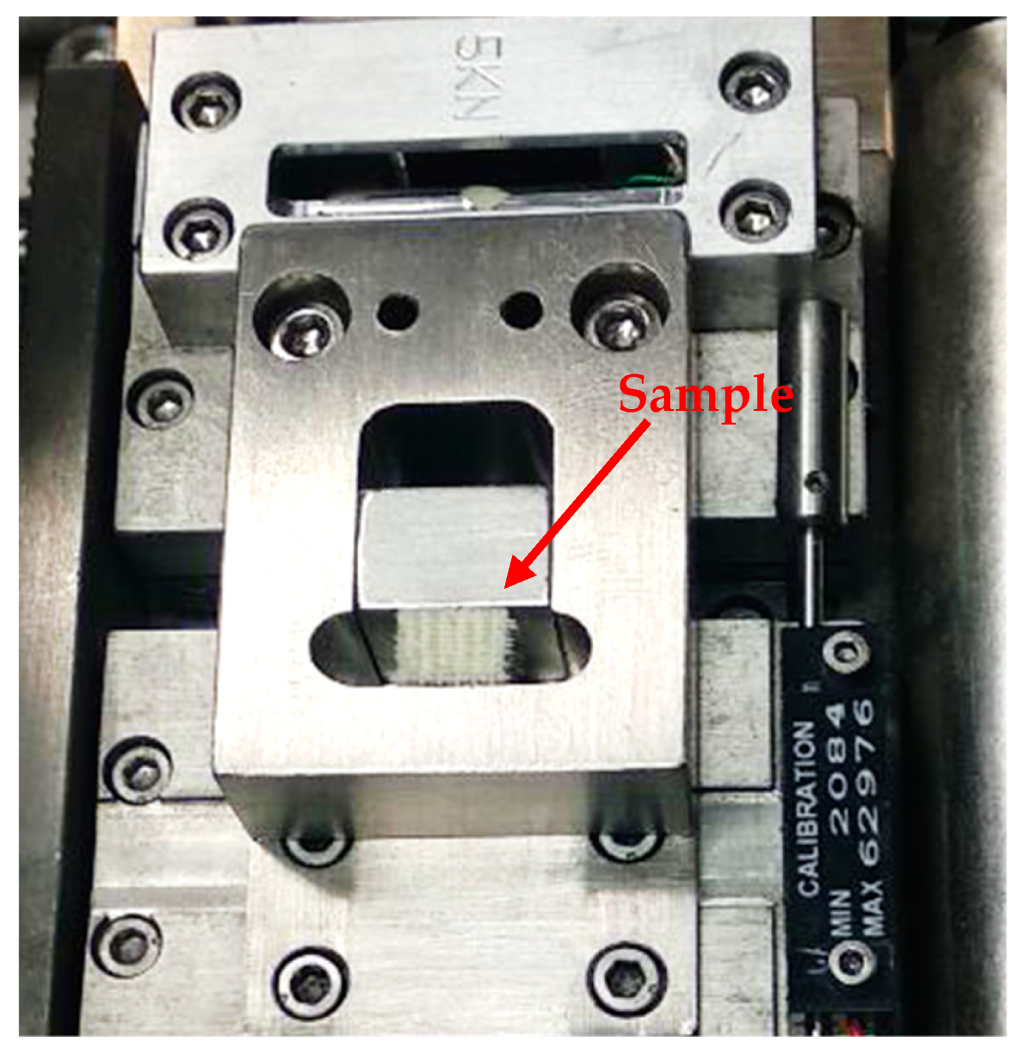
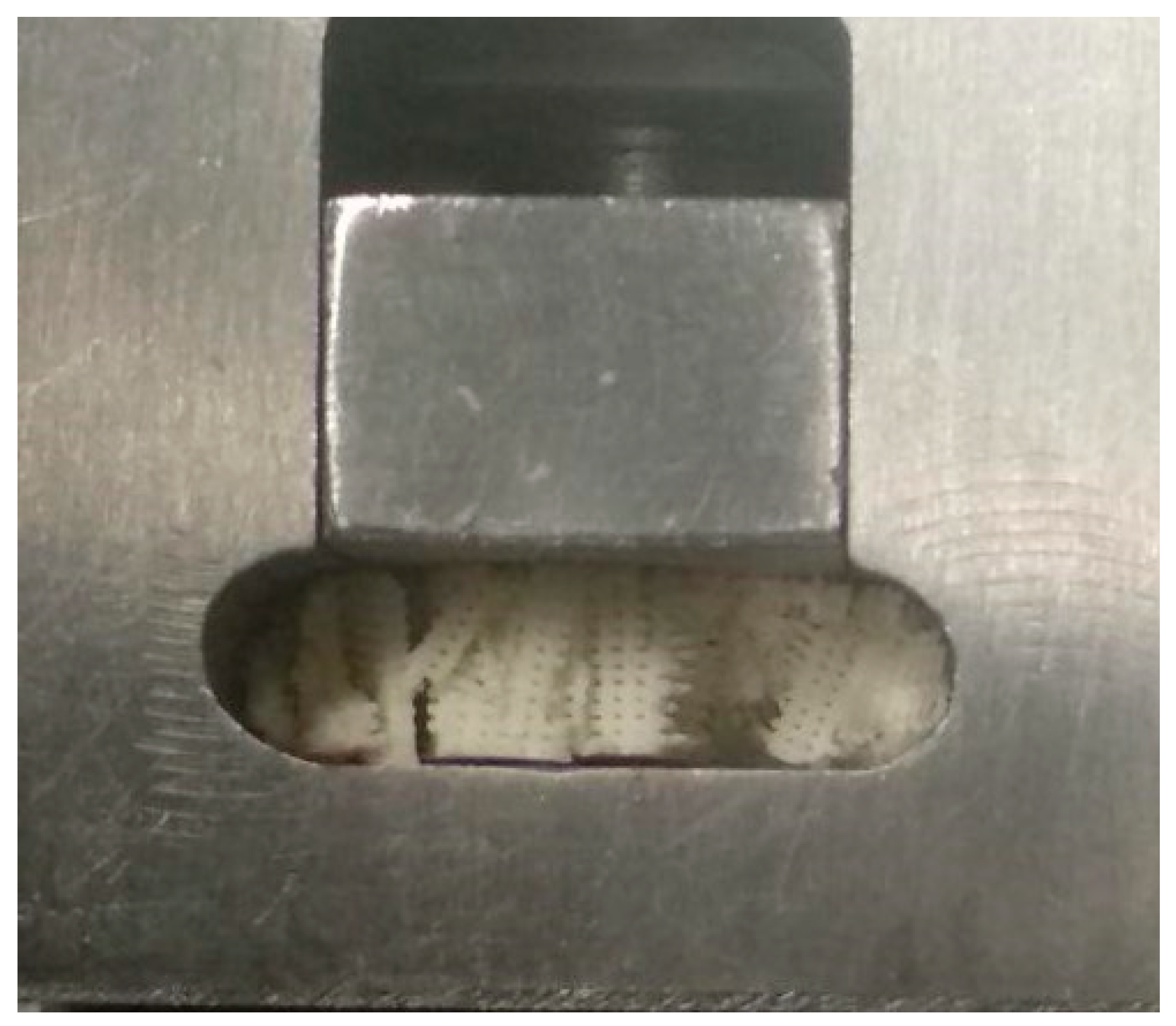
3.1.5. Mechanical Properties
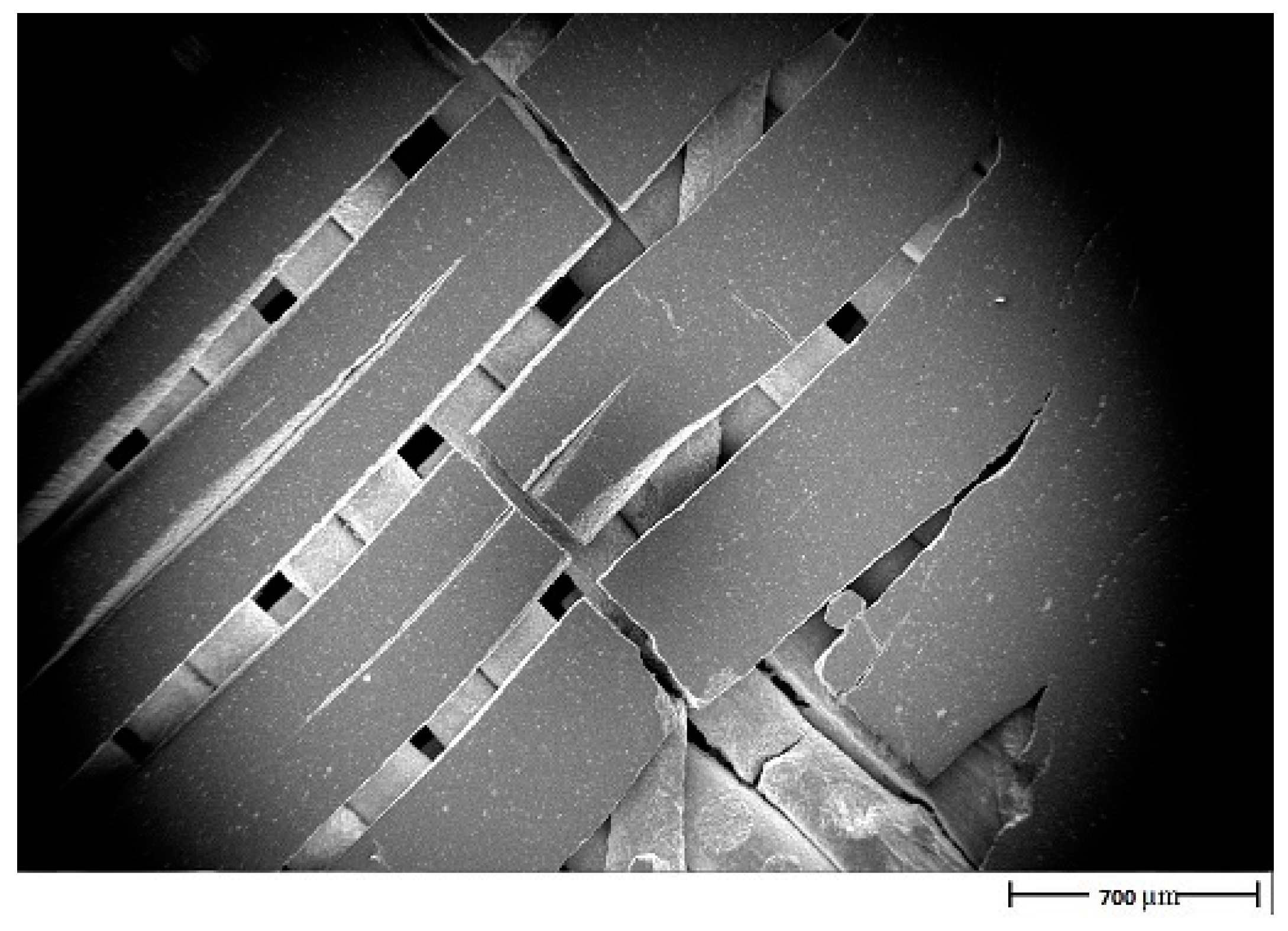
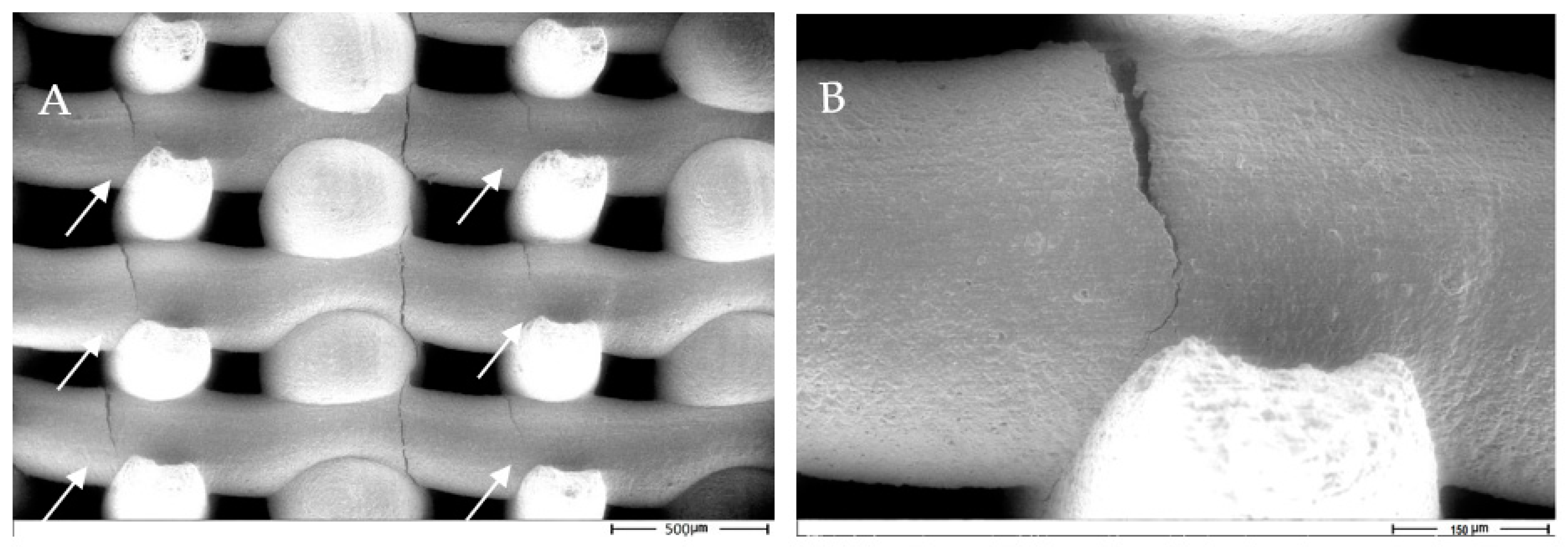
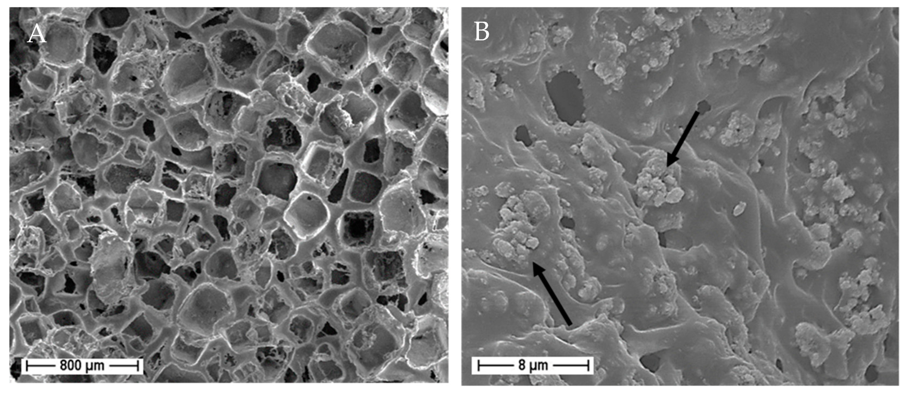
3.1.6. Fracture Mechanism Analysis
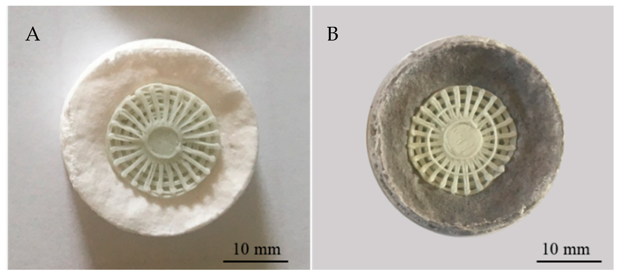
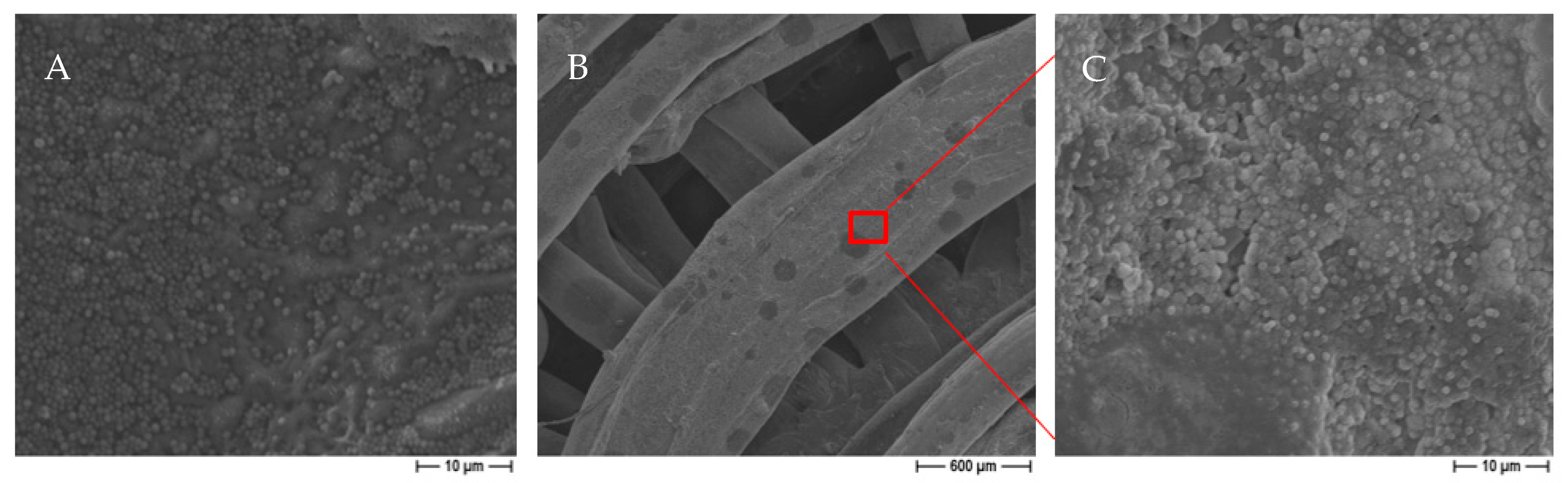
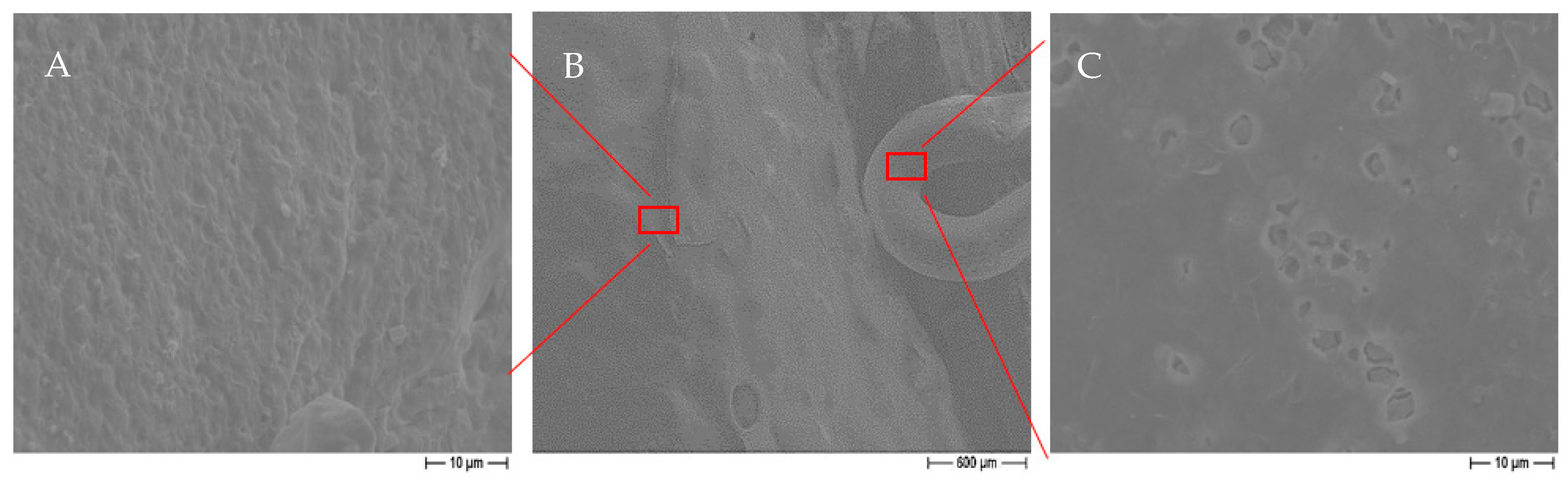
3.1.7. In Vitro Bioactivity Test
3.2. Hybrid Technologies for Ceramic/Polymer Scaffolds
4. Conclusions
Author Contributions
Funding
Acknowledgments
Conflicts of Interest
References
- Sultana, N. Biodegradable Polymer-Based Scaffolds for Bone Tissue Engineering; Springer: Berlin/Heidelberg, Germany; New York, NY, USA; Dordrecht, The Netherlands; London, UK, 2013. [Google Scholar] [CrossRef]
- Liu, H. Nanocomposites for Musculoskeletal Tissue Regeneration; Woodhead Publishing: Kidlington, UK, 2016. [Google Scholar]
- Brown, O.; McAfee, M.; Clarke, S.; Buchanan, F. Sintering of biphasic calcium phosphates. J. Mater. Sci. Mater. Med. 2010, 21, 2271–2279. [Google Scholar] [CrossRef] [PubMed]
- LeGeros, R.Z. Properties of osteoconductive biomaterials: Calcium phosphates. Clin. Orthop. Relat. Res. 2002, 395, 81–98. [Google Scholar] [CrossRef] [PubMed]
- Hench, L.L. An Introduction to Bioceramics, 2nd ed.; Imperial College Press: London, UK, 2013. [Google Scholar]
- Dorozhkin, S.V. Bioceramics of calcium orthophosphates. Biomaterials 2010, 31, 1465–1485. [Google Scholar] [CrossRef] [PubMed]
- Hwa, L.C.; Rajoo, S.; Mohd Noor, A.; Norhayati, A.; Uday, M. Recent advances in 3D printing of porous ceramics: A review. Curr. Opin. Solid State Mater. Sci. 2017, 21, 323–347. [Google Scholar] [CrossRef]
- Gauthier, O.; Bouler, J.M.; Aguado, E.; Pilet, P. Macroporous biphasic calcium phosphate ceramics: Influence of macropore diameter and macroporosity percentage on bone ingrowth. Biomaterials 1998, 19, 133–139. [Google Scholar] [CrossRef]
- Schephake, H.; Neukam, E.W.; Klosa, D. Influence of pore dimensions on bone ingrowth into porous hydroxylapatite blocks used as bone graft substitutes: A histometric study. Int. J. Oral Maxillofac. Surg. 1991, 20, 53–58. [Google Scholar] [CrossRef]
- Samavedi, S.; Whittington, A.R.; Goldstein, A.S. Calcium phosphate ceramics in bone tissue engineering: A review of properties and their influence on cell behavior. Acta Biomater. 2013, 9, 8037–8045. [Google Scholar] [CrossRef]
- Dorozhkin, S.V. Calcium orthophosphate bioceramics. Ceram. Int. 2015, 41, 13913–13966. [Google Scholar] [CrossRef]
- Cyster, L.; Grant, D.; Howdle, S.; Rose, F.; Irvine, D.; Freeman, D.; Scotchford, C.; Shakesheff, K. The influence of dispersant concentration on the pore morphology of hydroxyapatite ceramics for bone tissue engineering. Biomaterials 2005, 26, 697–702. [Google Scholar] [CrossRef]
- Tarafder, S.; Balla, V.K.; Davies, N.M.; Bandyopadhyay, A.; Bose, S. Microwave-sintered 3D printed tricalcium phosphate scaffolds for bone tissue engineering. J. Tissue Eng. Regen. Med. 2013, 7, 631–641. [Google Scholar] [CrossRef]
- Zhang, C.; Chen, F.; Huang, Z.; Jia, M.; Chen, G.; Ye, Y.; Lin, Y.; Liu, W.; Chen, B.; Shen, Q.; et al. Additive manufacturing of functionally graded materials: A review. Mater. Sci. Eng. A 2019, 764, 138209. [Google Scholar] [CrossRef]
- Lee, H.; Jang, T.S.; Song, J.; Kim, H.E.; Jung, H.D. The production of porous hydroxyapatite scaffolds with graded porosity by sequential freeze-casting. Materials 2017, 10, 367. [Google Scholar] [CrossRef] [PubMed]
- Fu, Q.; Rahaman, M.N.; Dogan, F.; Ba, B.S. Freeze-cast hydroxyapatite scaffolds for bone tissue engineering applications. Biomed. Mater. 2008, 3. [Google Scholar] [CrossRef] [PubMed]
- Wang, Q.; Wang, Q.; Wang, C. Preparation and evaluation of a biomimetic scaffold with porosity gradients in vitro. An. Acad. Bras. Ciênc. 2012, 84, 9–16. [Google Scholar] [CrossRef] [PubMed]
- Chamary, S.; Hautcoeur, D.; Hornez, J.C.; Leriche, A.; Cambier, F. Bio-inspired hydroxyapatite dual core-shell structure for bone substitutes. J. Eur. Ceram. Soc. 2017, 37, 5321–5327. [Google Scholar] [CrossRef]
- Pompe, W.; Worch, H.; Epple, M.; Friess, W.; Gelinsky, M.; Greil, P.; Hempele, U.; Scharnweber, D.; Schulte, K. Functionally graded materials for biomedical applications. Mater. Sci. Eng. A 2003, 362, 40–60. [Google Scholar] [CrossRef]
- Macchetta, A.; Turner, I.G.; Bowen, C.R. Fabrication of HA/TCP scaffolds with a graded and porous structure using a camphene-based freeze-casting method. Acta Biomater. 2009, 5, 1319–1327. [Google Scholar] [CrossRef]
- Sanchez-Salcedo, S.; Werner, J.; Vallet-Regi, M. Hierarchical pore structure of calcium phosphate scaffolds by a combination of gel-casting and multiple tape-casting methods. Acta Biomater. 2008, 4, 913–922. [Google Scholar] [CrossRef]
- Petit, C.; Tulliani, J.M.; Tadier, S.; Meille, S.; Chevalier, J.; Palmero, P. Novel calcium phosphate/PCL graded samples: Design and development in view of biomedical applications. Mater. Sci. Eng. C 2019, 97, 336–346. [Google Scholar] [CrossRef]
- Lewis, J.A.; Gratson, G.M. Direct writing in three dimensions. Mater. Today 2004, 7, 32–39. [Google Scholar] [CrossRef]
- Fu, Z.; Freihart, M.; Wahl, L.; Tobias Fey, T.; Greil, P.; Travitzky, N. Micro- and macroscopic design of alumina ceramics by robocasting. J. Eur. Ceram. Soc. 2017, 37, 3115–3124. [Google Scholar] [CrossRef]
- Marchi, C.S.; Kouzeli, M.; Rao, R.; Lewis, J.; Dunand, D. Alumina–aluminum interpenetrating-phase composites with three-dimensional periodic architecture. Scr. Mater. 2003, 49, 861–866. [Google Scholar] [CrossRef]
- Stanciuc, A.M.; Sprecher, C.M.; Adrien, J.; Roiban, L.I.; Alini, M.; Gremillard, L.; Peroglio, M. Robocast zirconia-toughened alumina scaffolds: Processing, structural characterisation and interaction with human primary osteoblasts. J. Eur. Ceram. Soc. 2018, 18, 845–853. [Google Scholar] [CrossRef]
- Feilden, E.; García-Tunón Blanca, E.; Giuliani, F.; Saiz, E.; Vandeperre, L. Robocasting of structural ceramic parts with hydrogel inks. J. Eur. Ceram. Soc. 2016, 36, 2525–2533. [Google Scholar] [CrossRef]
- Wahl, L.; Lorenz, M.; Biggemann, J.; Travitzky, N. Robocasting of reaction bonded silicon carbide structures. J. Eur. Ceram. Soc. 2019, 39, 4520–4526. [Google Scholar] [CrossRef]
- Eqtesadi, S.; Motealleh, A.; Miranda, P.; Lemos, A.; Rebelo, A.; Ferreira, J.M. A simple recipe for direct writing complex 45S5 Bioglasss 3D scaffolds. Mater. Lett. 2013, 93, 68–71. [Google Scholar] [CrossRef]
- Fu, Q.; Saiz, E.; Tomsia, A.P. Direct ink writing of highly porous and strong glass scaffolds for load-bearing bone defects repair and regeneration. Acta Biomater. 2011, 7, 3547–3554. [Google Scholar] [CrossRef] [Green Version]
- Barberi, J.; Nommeots-Nomm, A.; Fiume, E.; Verne, E.; Massera, J.; Baino, F. Mechanical characterization of pore-graded bioactive glass scaffolds produced by robocasting. Biomed. Glas. 2019, 5, 140–147. [Google Scholar] [CrossRef]
- Smay, J.E.; Nadkarni, S.S.; Xu, J. Direct writing of dielectric ceramics and base metal electrodes. Int. J. Appl. Ceram. Technol. 2007, 4, 47–52. [Google Scholar] [CrossRef]
- Maroulakos, M.; Kamperos, G.; Tayebi, L.; Halazonetis, D.; Ren, Y. Applications of 3D printing on craniofacial bone repair: A systematic review. J. Dent. 2019, 80, 1–14. [Google Scholar] [CrossRef]
- Zocca, A.; Colombo, P.; Gomes, C.M.; Gunster, J. Additive Manufacturing of Ceramics: Issues, Potentialities, and Opportunities. J. Am. Ceram. Soc. 2015, 98, 1983–2001. [Google Scholar] [CrossRef]
- Michna, S.; Wu, W.; Lewis, J.A. Concentrated hydroxyapatite inks for direct-write assembly of 3-D periodic scaffolds. Biomaterials 2005, 26, 5632–5639. [Google Scholar] [CrossRef] [PubMed]
- Miranda, P.; Pajares, A.; Saiz, E.; Tomsia, A.P.; Guiberteau, F. Mechanical properties of calcium phosphate scaffolds fabricated by robocasting. J. Biomed. Mater. Res. A 2008, 85, 218–227. [Google Scholar] [CrossRef] [PubMed]
- Martínez-Vázquez, F.J.; Perera, F.H.; Miranda, P.; Pajares, A.; Guiberteau, F. Improving the compressive strength of bioceramic robocast scaffolds by polymer infiltration. Acta Biomater. 2010, 6, 4361–4368. [Google Scholar] [CrossRef] [PubMed]
- Franco, J.; Hunger, P.; Launey, M.; Tomsia, A.; Saiz, E. Direct write assembly of calcium phosphate scaffolds using a water-based hydrogel. Acta Biomater. 2010, 6, 218–228. [Google Scholar] [CrossRef] [Green Version]
- Paredes, C.; Martínez-Vázquez, F.J.; Pajares, A.; Miranda, P. Development by robocasting and mechanical characterization of hybrid HA/PCL coaxial scaffolds for biomedical applications. J. Eur. Ceram. Soc. 2019, 39, 4375–4383. [Google Scholar] [CrossRef]
- Roleček, J.; Pejchalová, L.; Martínez-Vázquez, F.; Miranda González, P.; Salamon, D. Bioceramic scaffolds fabrication: Indirect 3D printing combined with ice templating vs. robocasting. J. Eur. Ceram. Soc. 2019, 39, 1595–1602. [Google Scholar] [CrossRef]
- Cesarano, J., III; Dellinger, J.G.; Saavedra, M.P.; Gill, D.D. Customization of load-bearing hydroxyapatite lattice scaffolds. Int. J. Appl. Ceram. Technol. 2005, 2, 212–220. [Google Scholar] [CrossRef]
- Miranda, P.; Pajares, A.; Saiz, E.; Tomsia, A.; Guiberteau, F. Fracture modes under uniaxial compression in hydroxyapatite scaffolds fabricated by robocasting. J. Biomed. Mater. Res. A 2007, 83, 646–657. [Google Scholar] [CrossRef]
- Martinez-Vazquez, F.J.; Perera, F.H.; Meulen, I.V.D.; Heise, A.; Pajares, A.; Miranda, P. Impregnation of b-tricalcium phosphate robocast scaffolds by in situ polymerization. J. Biomed. Mater. Res. A 2013, 101, 3086–3096. [Google Scholar] [CrossRef]
- Sorrentino, R.; Cochis, A.; Azzimonti, B.; Caravaca, C.; Chevalier, J.; Kuntz, M.; Porporati, A.A.; Streicher, R.M.; Rimondini, L. Reduced bacterial adhesion on ceramics used for arthroplasty applications. J. Eur. Ceram. Soc. 2018, 38, 963–970. [Google Scholar] [CrossRef]
- Ou, S.F.; Chung, R.J.; Lin, L.H.; Chiang, Y.C.; Huang, C.F.; Ou, K.L. A mechanistic study on the antibacterial behavior of silver doped bioceramic. J. Alloys Compd. 2015, 629, 362–367. [Google Scholar] [CrossRef]
- Yang, S.; Zhang, Y.; Yu, J.; Zhen, Z.; Huang, T.; Tang, Q.; Chu, P.K.; Qi, L.; Hongbo, L. Antibacterial and mechanical properties of honeycomb ceramic materials incorporated with silver and zinc. Mater. Des. 2014, 59, 461–465. [Google Scholar] [CrossRef]
- Balamurugan, A.; Balossier, G.; Laurent-Maquin, D.; Pina, S.; Rebelo, A.; Faure, J.; Ferreira, J. An in vitro biological and anti-bacterial study on a sol–gel derived silver-incorporated bioglass system. Dent. Mater. 2008, 24, 1343–1351. [Google Scholar] [CrossRef] [PubMed]
- Mohammadi, M.; Tulliani, J.M.; Palmero, P. Fabrication of dense and porous biphasic calcium phosphates: Effect of dispersion on sinterability and microstructural development. Int. J. Appl. Ceram. Technol. 2019, 16, 1797–1806. [Google Scholar] [CrossRef]
- ISO 10545-3. Ceramic tiles—Part 3: Determination of Water Absorption, Apparent Porosity, Apparent Relative Density and Bulk Density; International Organization for Standardization: Geneva, Switzerland, 2018. [Google Scholar]
- ASTM C773-88. Standard Test Method for Compressive (Crushing) Strength of Fired Whiteware Materials; American Society for Testing and Materials: West Conshohocken, PE, USA, 2016.
- Marcassoli, P.; Cabrini, M.; Tirillò, J.; Bartuli, C.; Palmero, P.; Montanaro, L. Mechanical Characterization of Hydroxiapatite Micro/Macro-Porous Ceramics Obtained by Means of Innovative Gel-Casting Process. Key Eng. Mater. 2009, 417, 565–568. [Google Scholar] [CrossRef]
- Benaqqa, C.; Chevalier, J.; Saädaoui, M.; Fantozzi, G. Slow crack growth behaviour of hydroxyapatite ceramics. Biomaterials 2005, 26, 6106–6112. [Google Scholar] [CrossRef]
- Palmero, P.; Fantozzi, G.; Lomello, F.; Bonnefont, G.; Montanaro, L. Creep behaviour of alumina/YAG composites prepared by different sintering routes. Ceram. Int. 2012, 38, 433–441. [Google Scholar] [CrossRef]
- ISO 23317. Ceramic Tiles—Part 3: Implants for Surgery—In Vitro Evaluation for Apatite-Forming Ability of Implant Materials; International Organization for Standardization: Geneva, Switzerland, 2014. [Google Scholar]
- Afghah, F.; Ullah, M.; Seyyed Monfared Zanjani, J.; Akkus Sut, P.; Sen, O.; Emanet, M.; Saner Okan, B.; Culha, M.; Menceloglu, M.; Yildiz, M.; et al. 3D printing of silver-doped polycaprolactone-poly(propylene succinate) composite scaffolds for skin tissue engineering. Biomed. Mater. 2020, 15. [Google Scholar] [CrossRef]
- Banche, G.; Allizond, V.; Bracco, P.; Bistolfi, A.; Boffano, M.; Cimino, A.; Brach Del Prever, E.M.; Cuffini, A.M. Interplay between surface properties of standard, vitamin E blended and oxidised ultra high molecular weight polyethylene used in total joint replacement and adhesion of Staphylococcus aureus and Escherichia coli. Bone Jt. J. 2014, 96, 497–501. [Google Scholar] [CrossRef]
- Cazzola, M.; Ferraris, S.; Allizond, V.; Bertea, C.M.; Novara, C.; Cochis, A.; Geobaldo, F.; Bistolfi, A.; Cuffini, A.M.; Rimondini, L.; et al. Grafting of peppermint essential oil to chemically treated Ti6Al4V alloy to counteract bacterial adhesion. Surf. Coat. Technol. 2019, 378, 125011. [Google Scholar] [CrossRef]
- Ferraris, S.; Spriano, S.; Miola, M.; Bertone, E.; Allizond, V.; Cuffini, A.M.; Banche, G. Bioactive and antibacterial titanium surfaces through a modified oxide layer and embedded silver nanoparticles: Effect of reducing/stabilizing agents on precipitation and properties of the nanoparticles. Surf. Coat. Technol. 2018, 344, 177–189. [Google Scholar] [CrossRef]
- Banche, G.; Bracco, P.; Allizond, V.; Bistolfi, A.; Boffano, M.; Cimino, A.; Brach Del Prever, E.M.; Cuffini, A.M. Do crosslinking and vitamin E stabilization influence microbial adhesions on UHMWPE-based biomaterials? Clin. Orthop. Relat. Res. 2015, 473, 974–986. [Google Scholar] [CrossRef] [Green Version]
- Rahaman, M.N. Ceramic Processing, 2nd ed.; CRC Press: Boca Raton, FL, USA, 2017. [Google Scholar] [CrossRef]
- Potoczek, M.; Zima, A.; Paszkiewicz, Z.; Slosarczyk, A. Manufacturing of highly porous calcium phosphate bioceramics via gel-casting using agarose. Ceram. Int. 2009, 35, 2249–2254. [Google Scholar] [CrossRef]
- Roopavath, U.K.; Malferrari, S.; Van Haver, A.; Verstreken, A.; Narayan Rath, S.; Kalaskar, D.M. Optimization of extrusion based ceramic 3D printing process for complex bony design. Mater. Des. 2019, 162, 263–270. [Google Scholar] [CrossRef]
- Martınez-Vazquez, F.; Pajares, A.; Miranda, P. Effect of the drying process on the compressive strength and cell proliferation of hydroxyapatite-derived scaffolds. Int. J. Appl. Ceram. Technol. 2017, 14, 1101–1106. [Google Scholar] [CrossRef]
- Palmero, P. Ceramic–polymer Nanocomposites for Bone-Tissue Regenerarion. In Nanocomposites for Musculoskeletal Tissue Regeneration; Woodhead Publishing: Duxford, UK, 2016; pp. 331–367. [Google Scholar]
- Seitz, H.; Rieder, W.; Irsen, S.; Leukers, B.; Tille, C. Three-dimensional printing of porous ceramic scaffolds for bone tissue engineering. J. Biomed. Mater. Res. B 2005, 74, 782–788. [Google Scholar] [CrossRef]
- Xin, R.; Leng, Y.; Chen, J.; Zhang, Q. A comparative study of calcium phosphate formation on bioceramics in vitro and in vivo. Biomaterials 2005, 26, 6477–6486. [Google Scholar] [CrossRef]
- Lu, X.; Leng, Y. Theoretical analysis of calcium phosphate precipitation in simulated body fluid. Biomaterials 2005, 26, 1097–1108. [Google Scholar] [CrossRef]
- Eidelman, N.; Chow, L.C.; Brown, W.E. Calcium phosphate saturation levels in ultrafiltered serum. Calcif. Tiss. Int. 1987, 40, 71–78. [Google Scholar] [CrossRef]
- Leeuwenburgh, S.C.; Wolke, J.G.; Siebers, M.C.; Schoonman, J.; Jansen, J.A. In vitro and in vivo reactivity of porous, electrosprayed calcium phosphate coatings. Biomaterials 2006, 27, 3368–3378. [Google Scholar] [CrossRef]
- Leng, Y.; Chen, J.; Qu, S. TEM study of calcium phosphate precipitation on HA/TCP ceramics. Biomaterials 2003, 24, 2125–2131. [Google Scholar] [CrossRef]
- Poh, P.S.; Hutmacher, D.W.; Holzapfel, B.M.; Solanki, A.K.; Stevens, M.M.; Woodruff, M.A. In vitro and in vivo bone formation potential of surface calcium phosphate-coated polycaprolactone and polycaprolactone/bioactive glass composite scaffolds. Acta Biomater. 2016, 30, 319–333. [Google Scholar] [CrossRef]
- Dziadek, M.; Stodolak-Zych, E.; Cholewa-Kowalska, K. Biodegradable ceramic-polymer composites for biomedical applications: A review. Mater. Sci. Eng. C 2017, 71, 1175–1191. [Google Scholar] [CrossRef]
- Chen, W.; Oh, S.; Ong, A.; Oh, N.; Liu, Y.; Courtney, H.; Appleford, M.; Ong, J. Antibacterial and osteogenic properties of silver-containing hydroxyapatite coatings produced using a sol gel process. J. Biomed. Mater. Res. 2007, 82A, 899–906. [Google Scholar] [CrossRef]
- Chen, W.; Liu, Y.; Courtney, H.; Bettenga, M.; Agrawal, C.; Bumgardner, J.; Ong, J. In vitro anti-bacterial and biological properties of magnetron co-sputtered silver-containing hydroxyapatite coating. Biomaterials 2006, 27, 5512–5517. [Google Scholar] [CrossRef]
- Karlov, A.; Shakhov, V.; Kolobov, J. Definition of silver concentration in calcium phophate coatings on titanium implants ensuring balancing of bactericidity and cytotoxicity. Key Eng. Mater. 2000, 192, 207–210. [Google Scholar] [CrossRef]


| Scaffold Type | Paste Code | Solid Loading (vol%) | Dispersant (%) | Methocel (%) | PEI (%) | Printing Speed (mm/min) |
|---|---|---|---|---|---|---|
| Lattice | P1 | 49.2 | 4 | 6.5 | 16 | 290 |
| P2 | 49.2 | 4 | 3.5 | 8 | 290 | |
| P3 | 51.0 | 4 | 6.5 | 8 | 290 | |
| Dense | P3 | 51.0 | 4 | 6.5 | 8 | 226 |
| Bi-layer | P3 | 51.0 | 4 | 6.5 | 8 | 129 |
| Scaffold Type | Strut Size (µm) | Pore Size (µm) | Apparent Density (g/cm3) | Density of Solid Part (g/cm3) | Relative Density of Solid (%) | Total Porosity (%) | Open Porosity (%) |
|---|---|---|---|---|---|---|---|
| Lattice | 341 ± 7 | 275 ± 8 | 2.06 ± 0.10 | 2.97 ± 0.01 | 95 | 34.1 | 30.7 ± 3.4 |
| Dense | - | - | 2.69 ± 0.20 | 2.95 ± 0.01 | 95 | 13.9 | 8.7 ± 1.6 |
| Bi-layer | 619 ± 21 | 605 ± 55– 1040 ± 31 | 2.19 ± 0.10 | 2.99 ± 0.01 | 96 | 29.9 | 26.8 ± 2.6 |
| External Diameter (mm) | Mean Pore Size (µm) | ||||||
|---|---|---|---|---|---|---|---|
| Core | 1° ring | 2° ring | 3° ring | 4° ring | 1° ring | 2° ring | 3° ring |
| 5.48 ± 0.11 | 7.92 ± 0.13 | 10.43 ± 0.15 | 13.02 ± 0.18 | 15.49 ± 0.35 | 605 ± 55 | 896 ± 52 | 1040 ± 31 |
| Ca | P | O | Si | Mg | Na | Ca/P |
|---|---|---|---|---|---|---|
| 15.44 | 11.63 | 71.4 | 0.32 | 0.56 | 0.65 | 1.33 |
| Sample Type | Ag-Doped Sample | Control Sample | R (%) |
|---|---|---|---|
| Adhered bacteria | 7.16 × 10⁴ ± 3.5 × 10⁴ | 3.22 × 10⁹ ± 3.07 × 10⁸ | 100.00 |
| Planktonic bacteria | 4.31 × 10⁴ ± 1.70 × 10⁴ | 2.97 × 10⁹ ± 3.82 × 10⁸ | 100.00 |
Publisher’s Note: MDPI stays neutral with regard to jurisdictional claims in published maps and institutional affiliations. |
© 2020 by the authors. Licensee MDPI, Basel, Switzerland. This article is an open access article distributed under the terms and conditions of the Creative Commons Attribution (CC BY) license (http://creativecommons.org/licenses/by/4.0/).
Share and Cite
Mohammadi, M.; Pascaud-Mathieu, P.; Allizond, V.; Tulliani, J.-M.; Coppola, B.; Banche, G.; Chaput, C.; Cuffini, A.M.; Rossignol, F.; Palmero, P. Robocasting of Single and Multi-Functional Calcium Phosphate Scaffolds and Its Hybridization with Conventional Techniques: Design, Fabrication and Characterization. Appl. Sci. 2020, 10, 8677. https://0-doi-org.brum.beds.ac.uk/10.3390/app10238677
Mohammadi M, Pascaud-Mathieu P, Allizond V, Tulliani J-M, Coppola B, Banche G, Chaput C, Cuffini AM, Rossignol F, Palmero P. Robocasting of Single and Multi-Functional Calcium Phosphate Scaffolds and Its Hybridization with Conventional Techniques: Design, Fabrication and Characterization. Applied Sciences. 2020; 10(23):8677. https://0-doi-org.brum.beds.ac.uk/10.3390/app10238677
Chicago/Turabian StyleMohammadi, Mehdi, Patricia Pascaud-Mathieu, Valeria Allizond, Jean-Marc Tulliani, Bartolomeo Coppola, Giuliana Banche, Christophe Chaput, Anna Maria Cuffini, Fabrice Rossignol, and Paola Palmero. 2020. "Robocasting of Single and Multi-Functional Calcium Phosphate Scaffolds and Its Hybridization with Conventional Techniques: Design, Fabrication and Characterization" Applied Sciences 10, no. 23: 8677. https://0-doi-org.brum.beds.ac.uk/10.3390/app10238677