Analysis of a Novel Automatic Control Approach for the Free Forging Hammer

State Key Laboratory of Materials Processing and Die & Mould Technology, Huazhong University of Science and Technology, Wuhan 430074, China
*
Author to whom correspondence should be addressed.
Appl. Sci. 2020, 10(24), 9127; https://0-doi-org.brum.beds.ac.uk/10.3390/app10249127
Submission received: 26 November 2020
/
Revised: 11 December 2020
/
Accepted: 18 December 2020
/
Published: 21 December 2020
(This article belongs to the Special Issue Industry 4.0 Based Smart Manufacturing Systems)
Abstract
:This paper proposes an electro-hydraulic servo control method and realizes the automatic control and remote control of free forging hammers for the first time. A configuration and control strategy for the program-control free forging hammer are constructed. Based on the configuration, a single-acting differential servo cylinder system is proposed to drive the follow-up spool valve and then control the motion state of the hammerhead. Furthermore, a non-contact measurement method is adopted to detect the real-time position of the hammerhead, and the installation position of the measuring sensor is isolated from the hammer body and foundation, thereby reducing the influence of vibration and impact on the accuracy of the feedback signal and ensuring the successive forming process of the forging hammer. In addition, a blow energy model of the forging hammer processing system is established, and a fuzzy-PID control scheme for the forging hammer is then adopted. Based on the control strategy, the striking accuracy of the proposed automatic forging hammer is significantly improved compared with the traditional forging hammer. Finally, the method is applied to an 8 MN forging hammer, and the results show its better processing performance than traditional hammers in terms of all indices.
1. Introduction
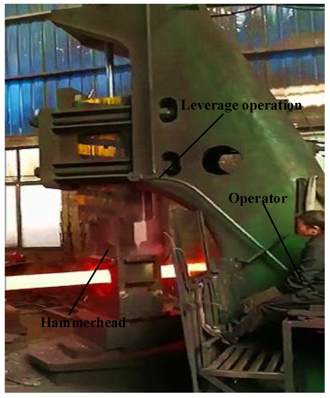
The forging hammer is preferred in metal forming because of its strong process adaptability, simple structure, convenient manipulation, and low investment cost. Since the birth of the first steam hammer in England in the 19th century, the forging hammer has been undergoing continuous technological transformation and upgrading, and has experienced many development stages, i.e., the air hammer, steam-air hammer, electrohydraulic pneumatic forging hammer, and all-hydraulic forging hammer [1,2,3]. During these stages, the shortcomings of the high energy consumption and large vibration of forging hammers have been significantly improved through increasing efforts of several generations of researchers. However, as reported by Espinoza [4] and Altan [5], several shortcomings still exist that cannot be solved, i.e., the low machining accuracy, high safety hazards, and low degree of automation, as shown in the Supplementary Materials and Figure 1. As the most versatile forging equipment, it is of great significance to improve the processing performance of the forging hammer production process.
To deal with the problems mentioned above, much research has been conducted to improve the control performance of the hydroforming equipment. Yao et al. [6] proposed a new compound control strategy of displacement and dual-pressure for the conventional electro-hydraulic proportional valve controlled fast forging system, and the results showed a significant energy saving effect. Kong et al. [7] employed a PID controller, integral separation controller, and fuzzy PID controller to control a 0.6 MN forging hydraulic press, and used simulation and experimental methods to study the control characteristics of the forging hydraulic press force closed-loop system under different control methods. The results show that the fuzzy PID could obtain better control effect and significantly improve the performance of forgings. Hao et al. [8] designed a self-tuning PID controller based on improved BP neural network, which could effectively suppress the time-varying system parameters, external interference, and other factors, thereby improving the dynamic quality of the smoothing mill closed-loop control system. Li et al. [9] studied the servo control principle of a novel die forging hammer and proposed the energy storage indirect conversion control method and conversion principle, which were shown to significantly improve the system energy efficiency and the controllability of the blow energy. Gerretsen et al. [10] compared the force closed loop, position closed loop, and speed closed loop control of forging hydraulic equipment, and provided theoretical guidance for subsequent references. Lizalde et al. [11] combined the second-order sliding mode control method with the neural network control scheme to study the force tracking performance of the electro-hydraulic control system, which significantly improved the machining accuracy of the equipment. Based on Lyapunov analysis, Alleyne et al. [12] proposed a new simplified algorithm to compensate for the uncertainty of the electro-hydraulic closed-loop control system and carried out experimental verification on a force/displacement servo hydraulic system.
Furthermore, researchers also focused on the energy model to improve the processing performance of the forging hammers. Zhang and Liu [13] presented a mathematical model of the full hydraulic die forging hammer based on the momentum theorem and then provided a theoretical reference for setting the blow energy and realized precise control of the die forging hammer operation process. Jin et al. [14] established a mathematical model of the 50 kJ die forging hammer’s striking energy and obtained the relationship between the striking stroke and the striking energy under a certain inflation pressure and mold loading height, providing a basis for program control of the hydraulic die forging hammer. Zhang et al. [15] developed an energy model for the opening time of the blow valve and the blow energy, which provides a reference for the program control of the die forging hammer and achieves good performance in the open loop control of the die forging hammer. Li et al. [16] established a new model of the die forging hammer based on the elastic deformation of the cushion under the anvil and deduced a theoretical calculation formula of the maximum hammering force, which provided a reference for the design and use of the die forging hammer. Electrohydraulic forging hammers can be divided into free forging hammers and die forging hammers and configurations of die forging hammers have been optimized by the above methods. However, improvements of the free forging hammer have rarely been reported thus far.
In addition to these methods, researchers have also focused on processing conditions and hammerhead compositions to improve the energy efficiency and processing performance of forging hammers. Jonas [17] studied the influence of friction on the forming effect of die forging hammers, and the results show that the upper mold achieves the best filling effect when the friction coefficient of the upper mold is about 0.2 and the friction coefficient of the lower mold is the maximum. Ren et al. [18] employed the continuous damage mechanics theory to analyze the fatigue damage problem of the forging hammer foundation system and provided theoretical guidance for the engineering application of the forging hammer. Lavrinenko and Shagaleev [19] studied the effect of the forging hammer composition on the deformation efficiency of lead workpieces and pointed out that a hammerhead filled with steel balls could improve the blow efficiency. Irisarri and Pelayo [20] proposed a failure detection method for the free forging hammer and pointed out that several ductile dimples would appear in the overload area, thereby resulting in fatigue cracks and hammer failure. The core aim of these methods is to improve the processing performance of the forging hammer by optimizing the composition and production environment through finite element analysis of the forging hammer equipment.
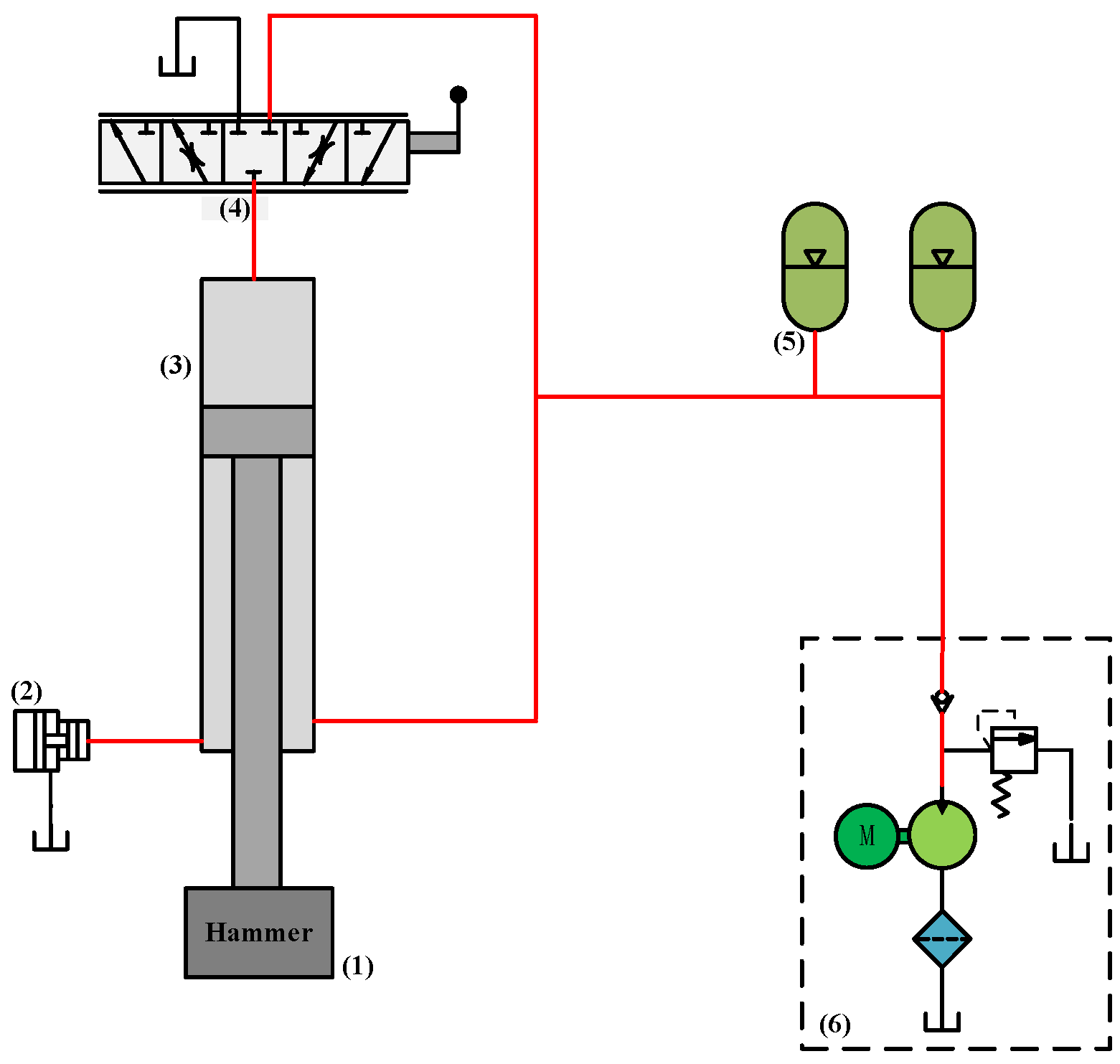
Since the die forging hammer works intermittently and the workpieces are formed by molds in which the mold height and manufactured parts are all relatively fixed, the forming energy changes between different working cycles are regular. Therefore, it is easy to realize program control for the die forging hammer. By controlling the opening time and beat of the blow valve, the blow energy and blow step can be controlled as required. Furthermore, the machining accuracy and control performance are significantly improved based on a variety of optimization algorithms, and all forming actions of a die forging hammer are completed by control buttons and programs. Therefore, most of the new die forging hammers on the market nowadays are programmed die forging hammers. However, because of the large randomness of the process requirements in the production process of free forging hammers, the energy changes frequently between different steps, and the strike frequency is faster than the die forging hammer. Therefore, the control method applied to the die forging hammer cannot adapt to the working mode of the free forging hammer, and it is difficult for the free forging hammer to realize its automatic control by adjusting the opening time and beat of the blow valve. As can be seen from Figure 1, motions of a free forging hammer are still realized by manually operating a set of lever mechanisms in front of the forging hammer, of which the working principle are shown in Figure 2. The operator continuously manipulates the forging hammer for a long time (80 times/min), and another operator controls the forging manipulator on the operating car, leading to a high labor intensity, strong heat radiation, a high level of noise, and a low processing accuracy of a free forging hammer.
In order to address this problem, this paper proposes a servo control scheme to realize the automation of the free forging hammer and improve the shortcomings mentioned above. A novel free forging hammer structure for this control scheme has been constructed. Automatic control and linkage control can be realized by a single-acting differential servo cylinder drive system and centralized processing of the real-time measurement of the hammerhead position and the reference routes. Moreover, high precision control of the striking energy can be achieved by a Fuzzy PID control scheme, which significantly improves the machining accuracy and shows a high tracking performance of the hammerhead.
The remainder of this paper is organized as follows. In Section 2, the automatic control methodology is described. The system structure and dynamic performance analysis are developed in Section 3. In Section 4, control schemes for free forging hammer are described, including blowing energy model and control strategy. Case study and results are presented in Section 5. Finally, conclusions are stated in Section 6.
2. Methodology
The above two forging hammers are controlled by manual operation of the slide valve. If a novel controller can be developed and used to substitute traditional manual control, then automatic control of the forging hammer can be realized. However, due to the randomness of the production process of the free forging hammer, the energy required between different working steps is different. Therefore, it is impossible to realize automatic control for the free forging hammer by the approach used in the current die forging hammer.
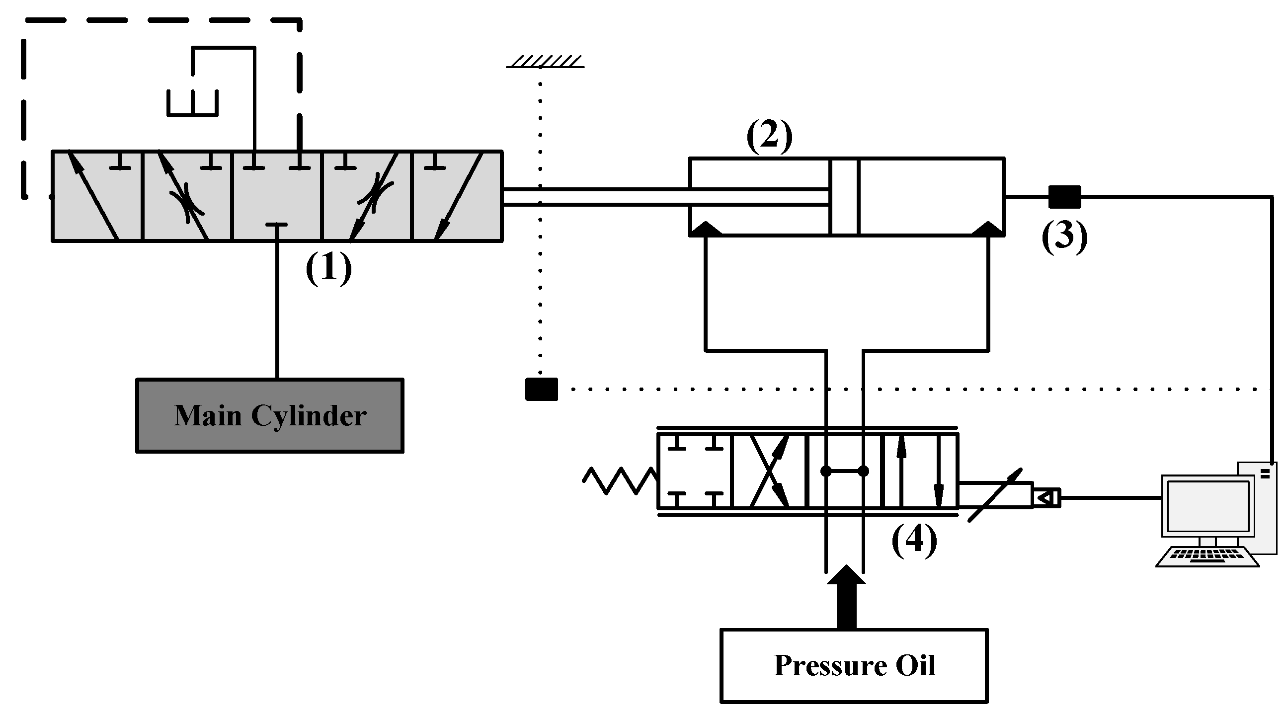
In fact, motions of a free forging hammer are controlled by a main control valve, namely the manual slider valve. Therefore, automation of a free forging hammer can be achieved through automatic control of the main control valve. However, as the manual slide valve has a transition state and is infinitely variable, the valve opening size and the valve on-off state can be accurately controlled by a servo control system. In this control system, movement of the main control valve spool is controlled by a servo cylinder instead of a traditional manual drive, in which the servo cylinder is controlled by an electrohydraulic servo valve. Based on this method, the hammerhead motion state composed of stopping, slow rising, slow falling, returning, and striking with different frequencies and routes can be realized automatically. Figure 3 is a schematic diagram of the electro-hydraulic servo control system.
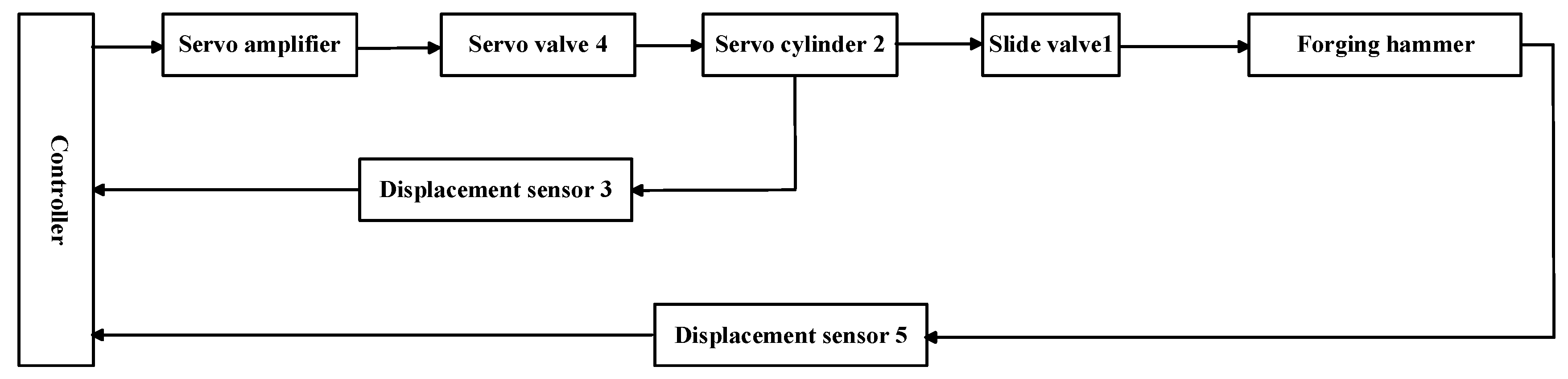
As shown in Figure 3, the main control valve 1 is employed to control the motion state of the hammerhead. According to the opening size, the spool speed and the on–off state of the main control valve 1, hammerhead motions composed of fast falling, pressure with slow falling, pressure maintaining, fast returning, slow returning, and other actions can be accurately realized. To achieve an automatic free forging hammer, the movement of the valve 1 spool is driven by a servo valve 4 controlled single-action servo hydraulic cylinder. Compared with traditional manual control of slide valve 1, not only the control accuracy, but also the manipulating agreeableness are significantly improved. Displacement sensor 3 is employed to measure the position of servo cylinder 2, and the real-time measured data are uploaded onto the upper PC after processing. Then, the upper PC sends a control signal to servo valve 4 under the overall consideration of the current position data from sensor 3 and a required position signal for the following operation. In this servo control system, the response speed and the advance site of cylinder 2 completely follow the given command signal from the controller. Furthermore, the position signal of the hammerhead is also detected, and then fed back to the controller. By analyzing the differential value between the actual position and the reference position, a control signal employed to adjust the hammerhead trajectory is sent to servo valve 4 to change the motion state of servo cylinder 2 and main control valve 1, thereby realizing the automatic operation of the free forging hammer according to the set parameters. The relevant control algorithm will be discussed in the following section. Figure 4 presents a control diagram of the electro-hydraulic free forging hammer.
The striking speed of the free forging hammer is up to 9 m/s, which produces a large impact and vibration on the forging hammer body and foundation. If the position detection device is installed on the hammer body, the sensor is easily damaged due to the large instantaneous acceleration, and the measured data contain a lot of noise, which poses a great challenge to the subsequent processing.
Therefore, this paper proposes a non-contact displacement measurement system based on the photoelectric effect to measure the position of the hammerhead. The measuring sensor is installed on the bracket drawn from the top of the operating room, which uses the movement of the forging hammer to block the light, and converts the light signal into an electrical signal output so as to obtain the real-time position of the forging hammer. In this detecting system, the measuring sensor is isolated from the hammer body and the foundation, and the impact and vibration during striking do not affect the measuring accuracy of the sensor. Meanwhile, the sensor installation does not affect the on-site operation, and the on-site operation does not damage the sensor. On the premise of not affecting the measurement accuracy, it is beneficial to protect the measurement sensor and prolong its service life.
3. System Structure and Dynamic Performance Analysis
3.1. Configuration of an Automatic Free Forging Hammer
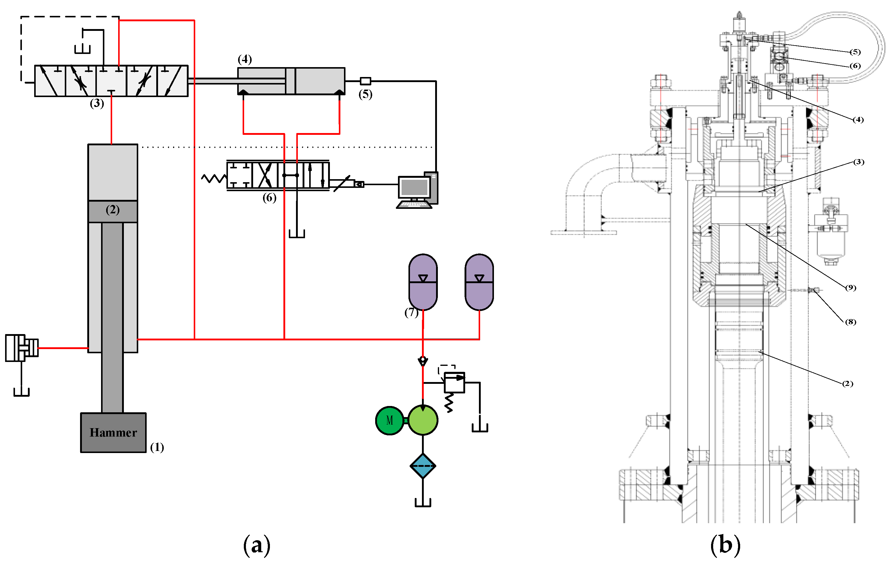
Figure 5 shows the configuration of a free forging hammer controlled by the proposed automatic control system. Main control valve 3, which controls the oil inlet and outlet of the upper cavity of forging hammer cylinder 2, is a three ways, three positions slide valve with a cone seal. A servo control system, composed of servo valve 6, servo cylinder 4, and displacement sensor 5, is used to control the operation of servo cylinder 4. Floating valve 3 is driven by servo cylinder 4 at different speeds and different displacements, thereby realizing different operations of the forging hammerhead. The main components of the proposed control system are arranged from top to bottom along the vertical direction, as shown in Figure 5b. Servo cylinder 4 and main control valve 3 are rigidly connected, and the rod tail of the cylinder and the head of the valve core are fixed by bolts to ensure the stability and accuracy of displacement/force transmission. A buffer area is arranged between main control valve 3 and main working cylinder 2, thereby preventing the main control valve from being damaged by excessive pressure in the upper chamber during the return stroke. In addition, sensors 5 and 8 are installed on the bracket drawn out from the top of the operating room, and the installation position is isolated from the hammer body, which reduces the impact of vibration and shock on the measurement accuracy during the forging process.
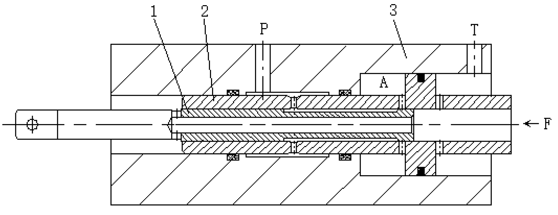
Main control valve 3 is composed of pilot valve 1, slave valve 2, valve body 3, etc., as shown in Figure 6. The force and displacement output from slave valve 2 directly drive the floating valve to control operations of the hammerhead. When pilot spool 1 is moved to the right by the drive of the servo cylinder, the valve port of pilot spool 1 to cavity A opens, and the pressure oil enters cavity A from port P, pushing slave valve 2 to the right. As spool valve 2 reaches the set place of pilot spool 1, the valve port closes and slave valve 2 stops moving. The displacement and speed of slave valve 2 follow pilot valve 1, and at the same time, the right end of slave valve 2 outputs a certain displacement and force to drive the floating valve, thereby connecting the upper chamber of the main working cylinder with the fuel tank. The main working cylinder drains and the hammerhead returns under the pressure of the accumulator.
Similarly, when the servo cylinder drives pilot spool 1 to the left, chamber A in the valve body discharges oil and the pressure decreases. Slave valve 2, driven by the floating valve, moves to the left simultaneously with the floating valve, leading to a connection between the upper chamber and accumulators. Then, the piston of the main working cylinder realizes the downward strike under the action of hydraulic differential power and the dead weight of the hammerhead.
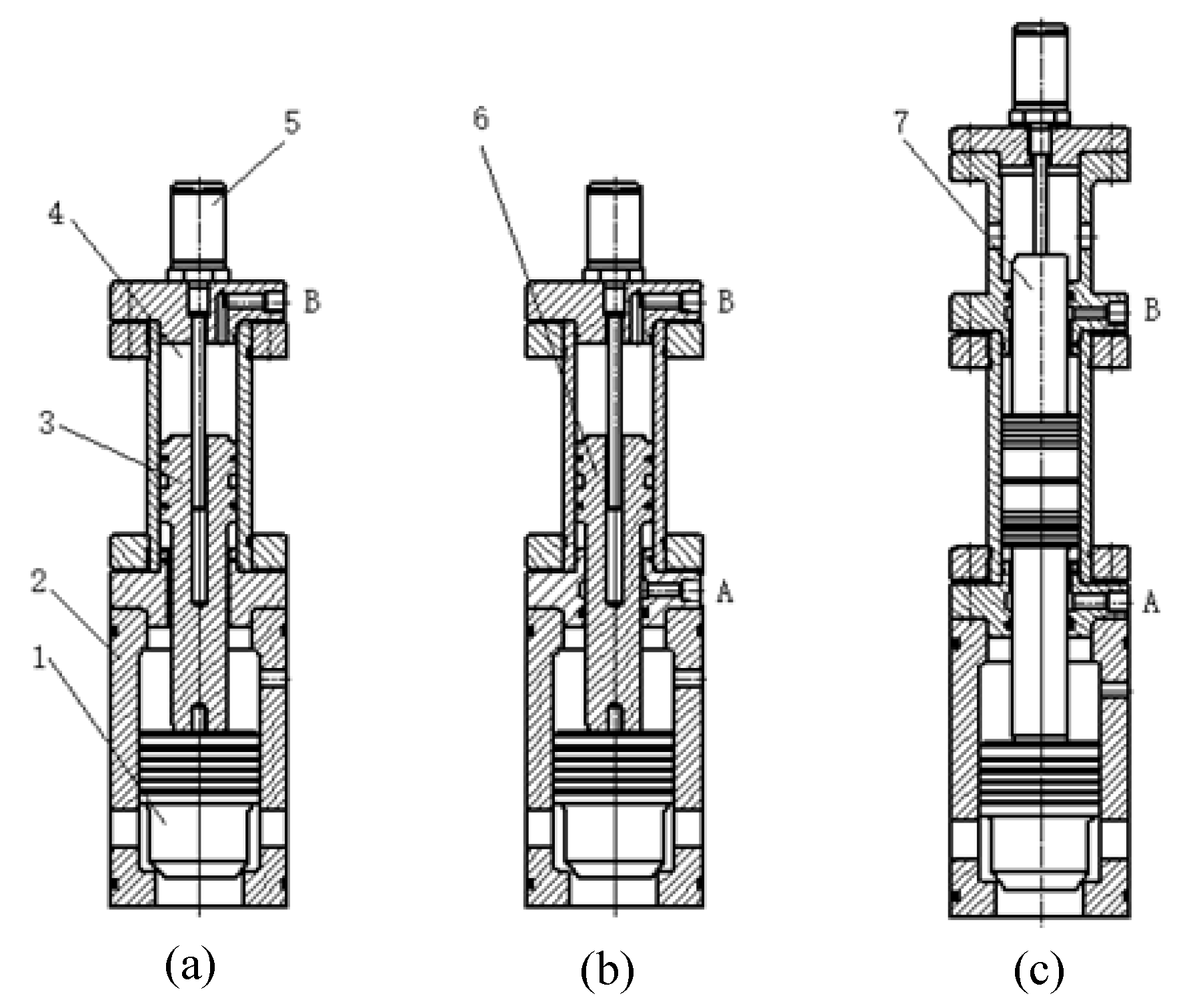
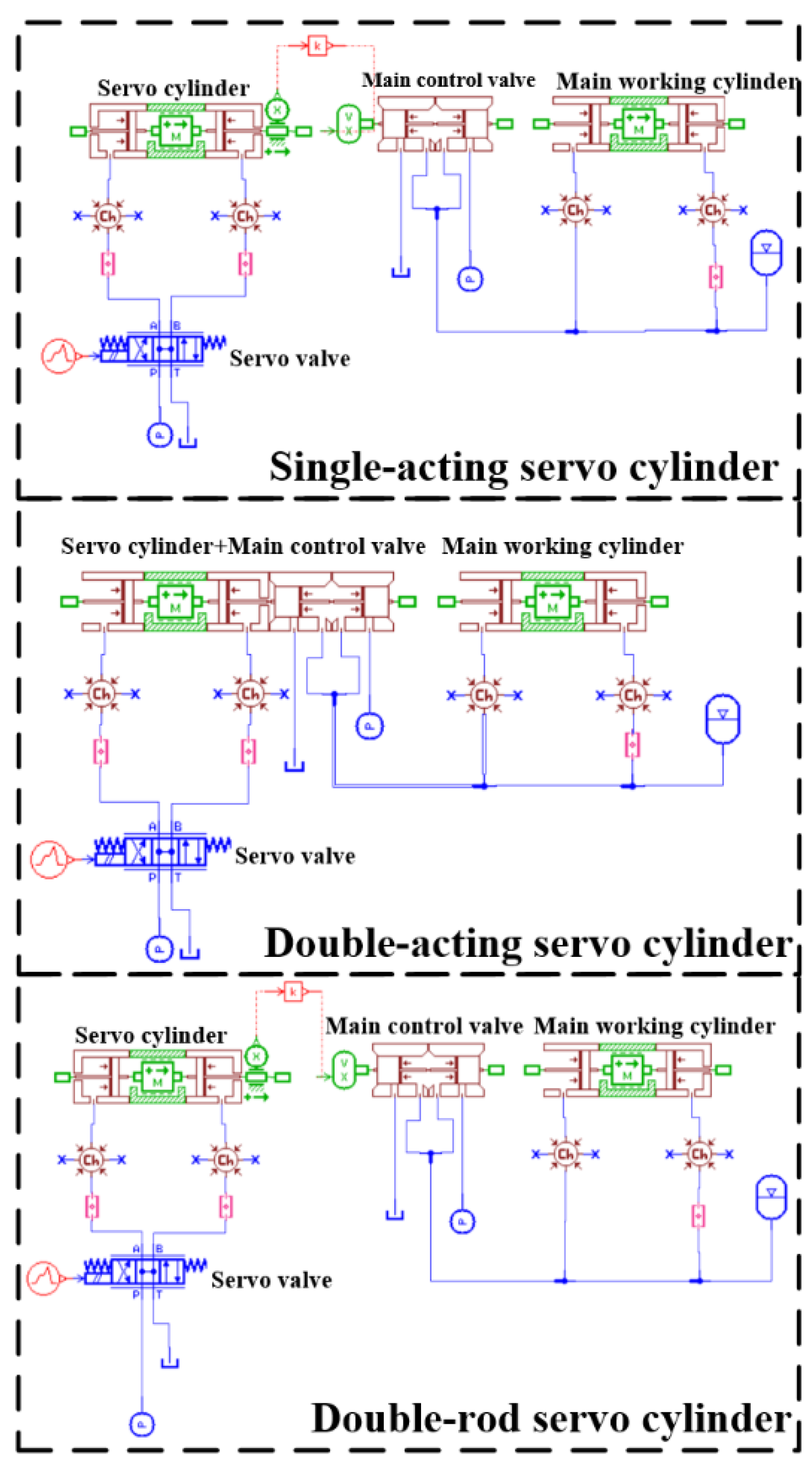
Since the forging frequency and forging efficiency are both realized by the main control valve, the dynamic performance of it is a key factor in determining the performance of the entire system. However, the response performance of the main control valve is determined by the dynamic characteristics of the servo cylinder. Therefore, three servo cylinders with different structures are studied in this paper, as shown in Figure 7. Figure 7a is the principle diagram of a single-acting cylinder. When hydraulic oil enters the servo cylinder chamber from port B, piston 3 moves down and drives main control valve 1 down. Then, the upper chamber of the main cylinder drains and the hammerhead returns. As oil discharges from port B, floating valve 1, driven by the pressure oil at the bottom, moves up and pushes piston 3 back. Meanwhile, recovery accumulators connect to the upper chamber of the main cylinder and the hammerhead strikes downward. Figure 7b is the principle diagram of a double-acting cylinder, while the motion state of piston 6 is controlled by both port A and port B. Figure 7c is the principle diagram of the double-rod cylinder, of which the working process is the same as Figure 7b. However, the piston rods of servo cylinder 4 have the same size at both ends, and the chamber volumes of A and B are the same. The dynamic performance of the free forging hammer with different servo cylinders will be studied in the following section.
3.2. Dynamic Performance Analysis
In order to study the dynamic characteristics of the servo drive system with different servo cylinders, AMESim can be adopted to model and simulate the servo control system, and the dynamic response of the forging hammer under different servo drive systems can then be obtained, combined with the actual operation effect.
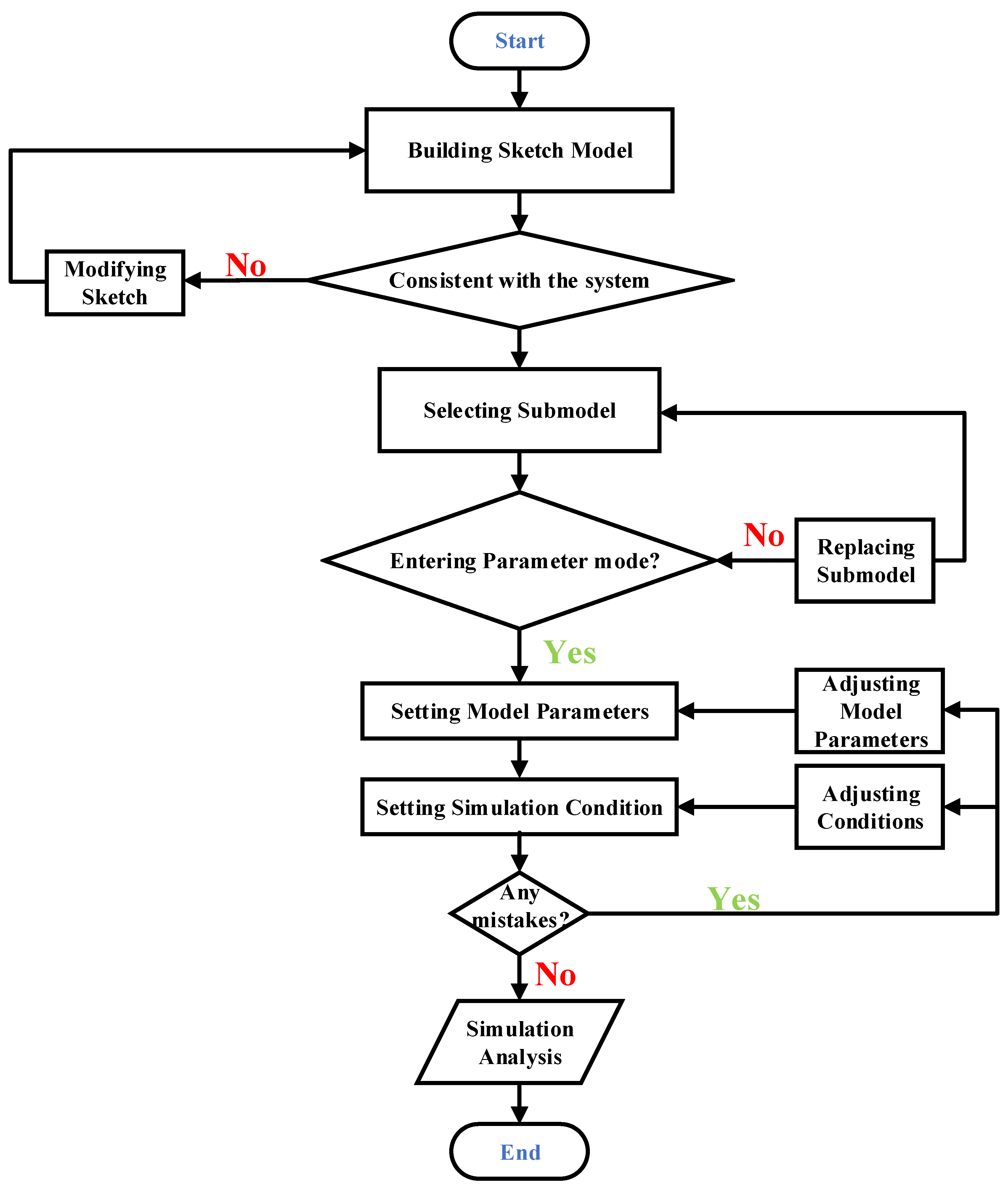
AMEsim uses ISO symbols to represent various components related to mathematical descriptions. Furthermore, AMESim provides users with optional libraries, such as the hydraulic component design library, the signal library, and the mechanical library, and users can select submodel and set parameters after building the appropriate sketch model. Figure 8 presents a flow chart of AMESim simulations. According to the flow chart, the physical simulation model of the servo control system can be established based on the hydraulic schematic diagram, as shown in Figure 9. Table 1 includes the main parameters of the simulation model.
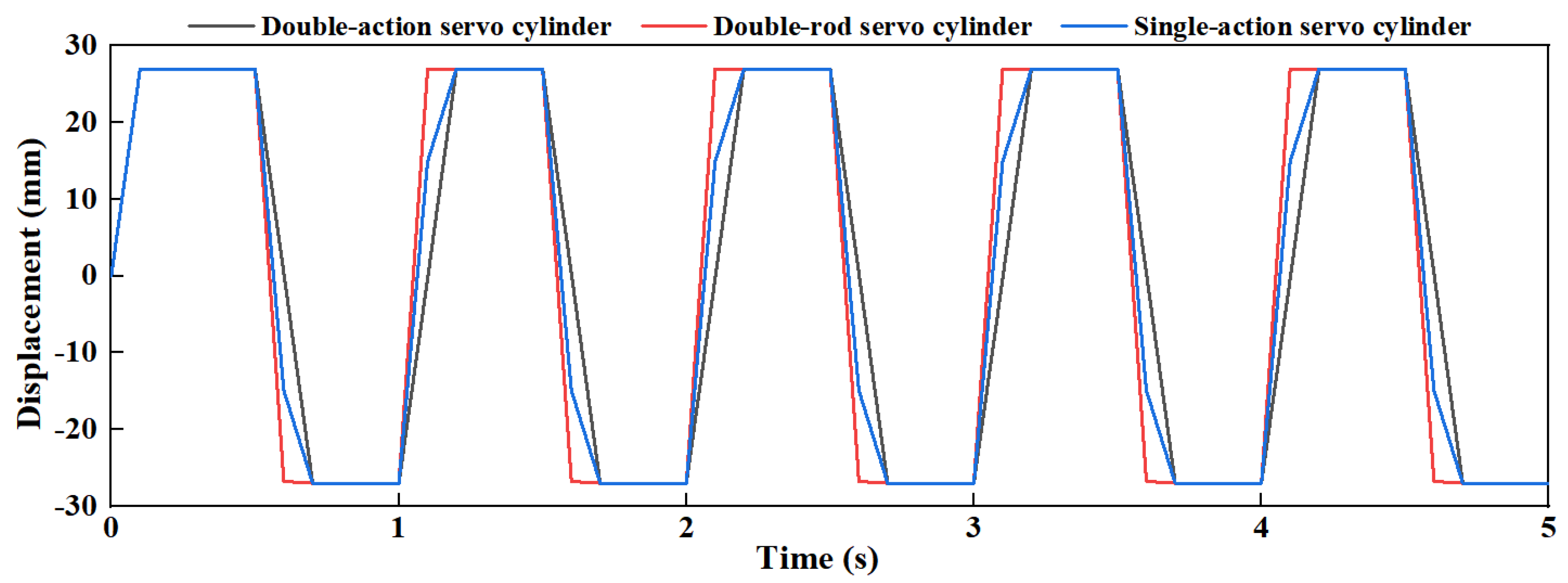
During a working cycle, the dynamic responses of the servo control system with different cylinder structures are shown in Figure 10. It can be seen from Figure 10 that the simulation results are basically consistent with the experimental results, verifying the effectiveness of the physical model built in AMESim. From the response curve, three servo cylinders can all meet the control requirements of the forging hammer. The double-rod cylinder is a symmetric cylinder with the best response characteristics, followed by the single-acting cylinder, and the worst is the double-acting cylinder. However, in terms of the actual assembly process, since the oil circuit and assembly structure of the single-acting cylinder is simpler than the double-rod cylinder and the dynamic response time between the single-acting cylinder and the double-rod cylinder exhibits little difference, the single-acting servo cylinder is the best choice for realizing automatic control for a free forging hammer. In addition, due to the vibrations of the displacement sensor when the hammerhead strikes, some volatility also exists in the measured response data, but the overall trend is consistent with the simulations.
4. Control Schemes for Free Forging Hammer
4.1. Blow Energy Model
For a servo free forging hammer, the forging energy carried by the hammerhead each time the forging hammer descends to strike the forging is determined by the thrust and the descend speed of the piston rod. Therefore, the output energy of the hammerhead () in a working stroke can be expressed as,
where and are the start time and the end time of the downward strike, respectively; is the thrust of the piston rod; and is the position of the piston rod in the vertical direction.
Since the hydraulic cylinder driving the hammerhead is connected in a differential connection, its thrust and descending speed () can be described by,
where is the pressure inside the upper chamber of the main cylinder; and are the ram areas of the two chambers; is the flow rate supplied to the upper chamber; and and are the mechanical efficiency and volumetric efficiency of the main cylinder, respectively. Therefore, the output energy can be rewritten as follows,
When the upper chamber feeds, the flow rate from the main control valve into the main cylinder that controls the movement of the forging hammer can be obtained as follows according to fluid mechanics:
where and are the discharge coefficient and spool area gradient, respectively; is the oil density; is the spool displacement; and is the supply pressure.
The working principle of the main control valve is basically the same as that of the electromagnetic valve, which is based on adjusting the spool displacement to change the output flow and output pressure of the main control valve. The only difference is that the power source for the spool is different. In this system, a servo cylinder is adopted to drive the main control valve, and the servo cylinder and the main control valve are rigidly connected, so the displacement of the servo cylinder is the displacement of the main control valve spool. According to the mechanics, the servo cylinder force balance equation can be described by
where and are the ram areas of the two chambers; and are the pressure inside the two chambers; is the mass of the main control valve spool; represents the viscous friction coefficient; and denotes deformation resistance.
Then, the speed of the spool can be written as
where is the flowrate supplied to the rodless cavity and can be expressed as follows,
where is the supplied pressure of the servo valve; is the flowrate gain coefficient of the servo valve; and , where is a positive constant and is the control input.
Therefore, Equation (8) can be rewritten as,
Therefore, the striking energy of the hammerhead can be controlled automatically and obtained as,
By adjusting the input signal , motion state control of the servo cylinder and the main cylinder can be realized, thereby realizing control of the striking energy of the forging hammer. Unlike die forging, since there are many variable forging shapes and the randomness of the production process is too large, the energy switching between different steps is frequent during the free forging process. Through integrating the proposed servo drive system into the hydraulic system of the free forging hammer, automatic control of the energy of the forging hammer can be realized, which is true automatic control in the strict sense.
4.2. Control Strategy
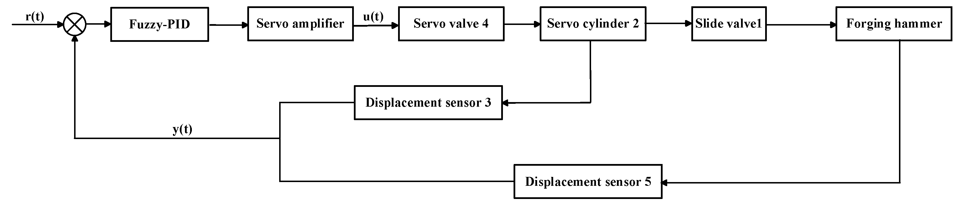
In order to increase the machining accuracy and achieve high precision control, the input signal u must be processed before it can be sent out. To achieve this goal, a control scheme for the free forging hammer is established in Figure 11. As a large amount of external disturbance exists in the forging process, it is difficult for the traditional control method to achieve precise control of the striking energy. Therefore, a control method that combines fuzzy control and PID control is adopted in this paper. The online tuning of the key PID parameters through fuzzy control not only has the flexibility and speed of fuzzy control, but also inherits the advantages of the high precision of the PID control algorithm, so as to realize high-performance tracking control of the free forging hammer striking system.
The PID controller is composed of a proportional unit (P), an integral unit (I), and a differential unit (D). The actual control signal is adjusted according to the control deviation e(t) formed by the given value r(t) and the actual output value y(t). After discretization, the PID control output equation can be described by
where is the PID control quantity; is the scale factor; is the integral coefficient; is the differential coefficient; is the sampling period; and is the sampling number, where .
Although the PID control algorithm is widely used in the field of industrial automation control, it also has its shortcomings. In general PID control systems, PID parameters are determined and unchanged in the entire manufacturing process. However, for some systems with strong coupling, time-varying parameters, and nonlinearity, conventional PID control can hardly meet the control requirements. Therefore, in order to take advantage of PID adjustment and improve the disadvantages of parameter invariance, this paper combines fuzzy control method with PID control theory to achieve the best adjustment of PID parameters. , , and are tuned online, according to different deviation and the deviation change rate . After obtaining the new , , and , the conventional PID controller outputs the control signal to the controlled object, which improves the adaptability of the PID algorithm, as shown in Figure 12.
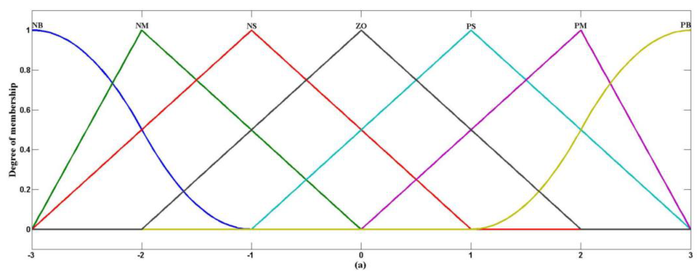
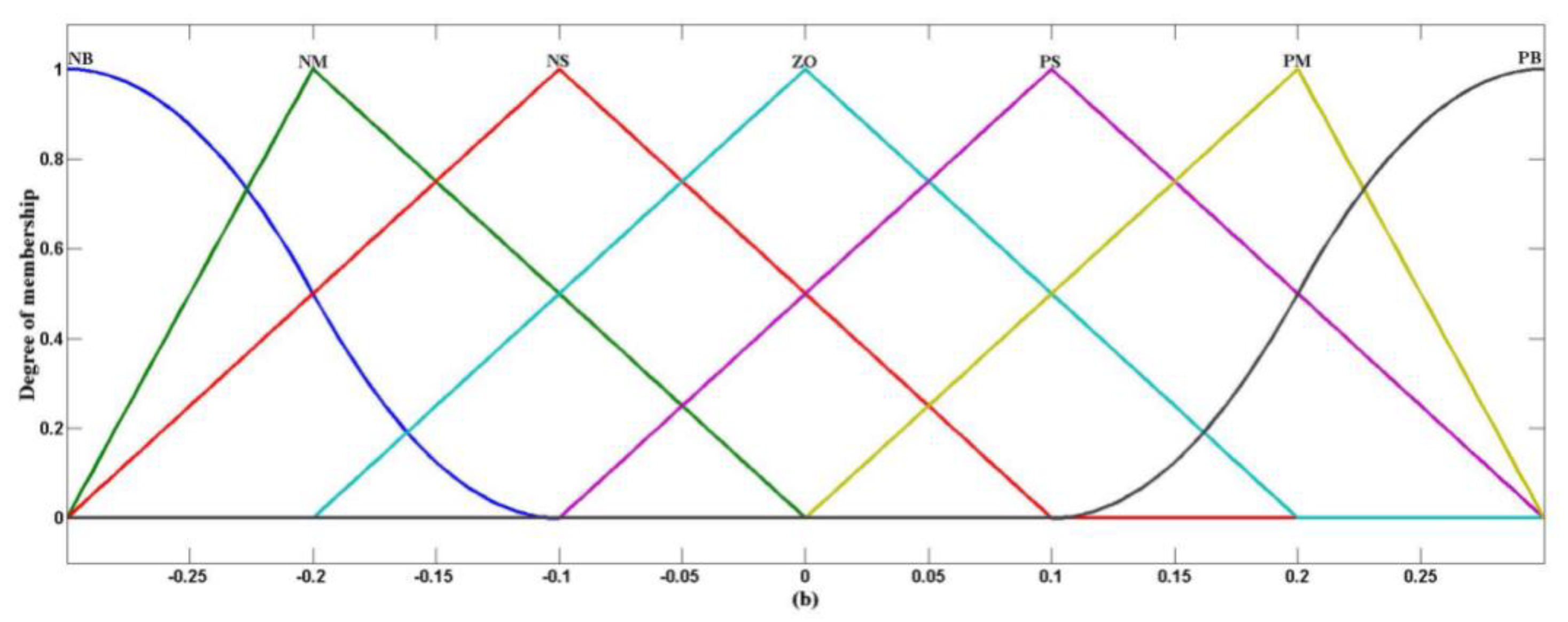
From Figure 12, the PID controller is calibrated by the fuzzy controller. Deviation and the deviation rate are used as the input, and the corrections of three parameters (, and ) are used as the output. The basic domain of , , and is {−3, −2, −1, 0, 1, 2, 3}, and the basic domain of and is {−0.3, −0.2, −0.1, 0, 0.1, 0.2, 0.3}. The fuzzy subset is divided into seven levels (including NB–negative big, NM–negative medium, NS–negative small, Z–Zero, PS–positive small, PM–positive middle, and PB–positive big). The membership function of each variable selects the z-shaped membership function on the left, the s-shaped membership function on the right, and the combined function form of the trigonometric function in the middle. The membership curves of , , , , and are shown in Figure 13. Control rules of parameters , , and are shown in Table 2. According to the control rules, the fuzzy relation () of PID parameters can be expressed as follows:
where is the fuzzy relation of , is the fuzzy relation of , and is the fuzzy relation of PID parameter .
According to the input of e and , the adjustment value can be calculated as follows.
where is the transpose of .
According to the membership function of each fuzzy variable and the fuzzy control model of each parameter, the real-time PID parameters can be updated as follows.
where is the initial value of . According to Equation (14), the output value of the controller is the control parameter value of the electro-hydraulic proportional control system and the input value of the electrohydraulic servo valve.
5. Case Study and Discussion
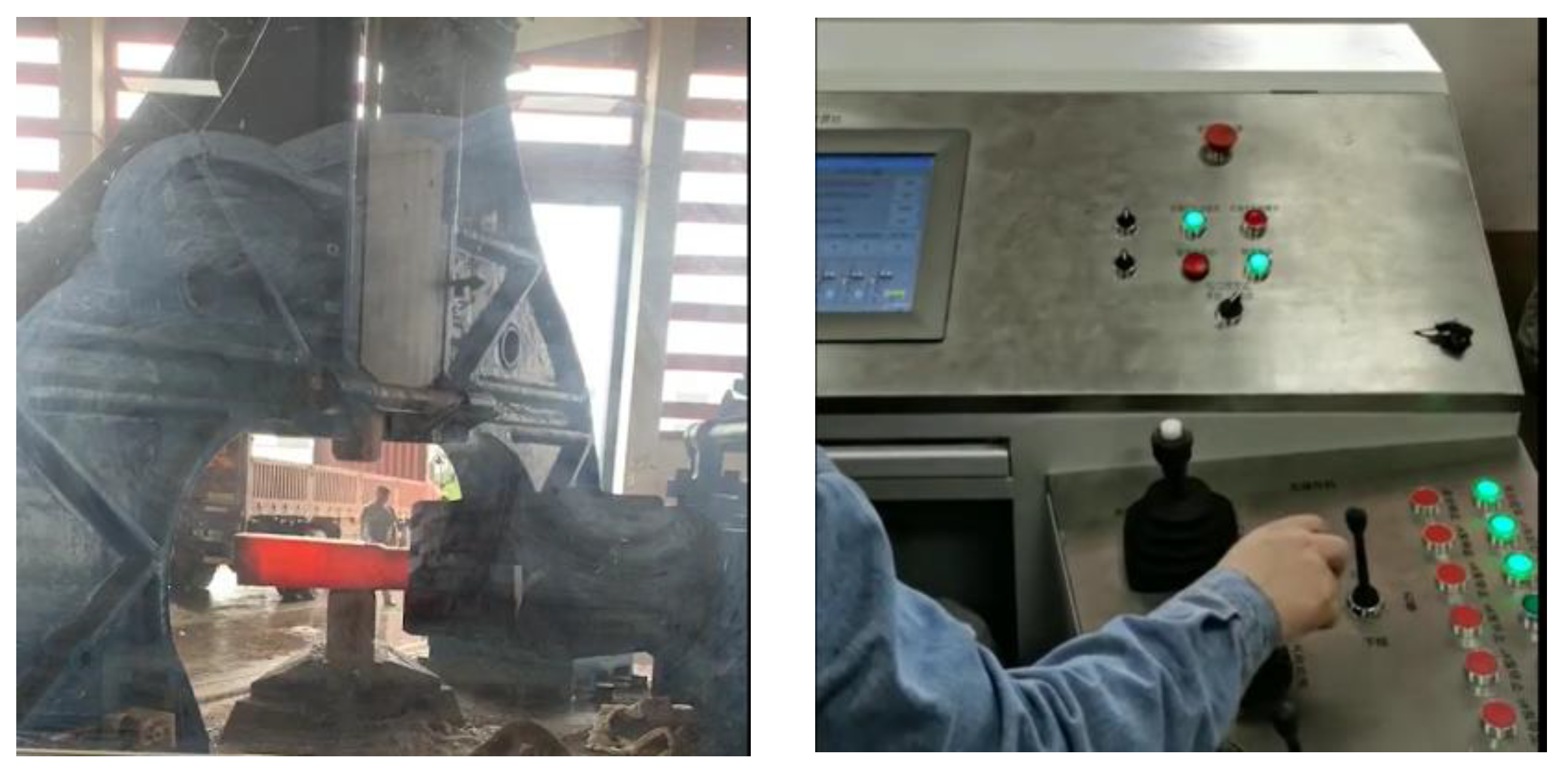
To illustrate the machining performance and control precision of the proposed free forging hammer, a test verification platform was set up, as shown in Figure 14, consisting of a control station mainly containing a host industrial computer and an operating handle, host equipment containing a forging hammerhead (whose mass was 760 kg), two displacement sensors (PY102C), a servo control valve (ATOS DLKZOR), a servo cylinder whose stroke was 30 mm, a main working cylinder whose stroke was 1 m, an A/D card (Advantech PCI-1716), and a D/A card (Advantech PCI-1723). In addition, the control system, with a 250 Hz sampling frequency, was composed of monitoring software and real-time control software, and this sampling rate was employed for both data collection and system control.
5.1. Experiments
Three sets of comparative experiments are described in this section, for which the trajectory references were set as 0.3 m, m, and m, respectively. The first command aimed to illustrate the dynamic performance of the proposed system under a unit step response, the second command was set to evaluate the performance of a normal-level motion trajectory (constant forging process), and the third one tried to verify its performance for a fast motion trajectory (fast forging process).
To evaluate the effectiveness of the proposed free forging system, the following three controllers were tested and compared:
- (1)
- TC: This is the traditional controller (TC) without any other adjustment during the control process, in which the position of the main cylinder is adjusted by the given pass or an operating handle;
- (2)
- PID: This is the Proportional–Integral–Derivative controller. The key parameters , and are tuned by trial and error methods and set as 100, 200, and −5, respectively;
- (3)
- Fuzzy-PID: This is the composite controller, which combines the PID controller and fuzzy controller. PID parameters are tuned online by the fuzzy controller, in which the specific fuzzy rules are shown in Table 2.
5.2. Results
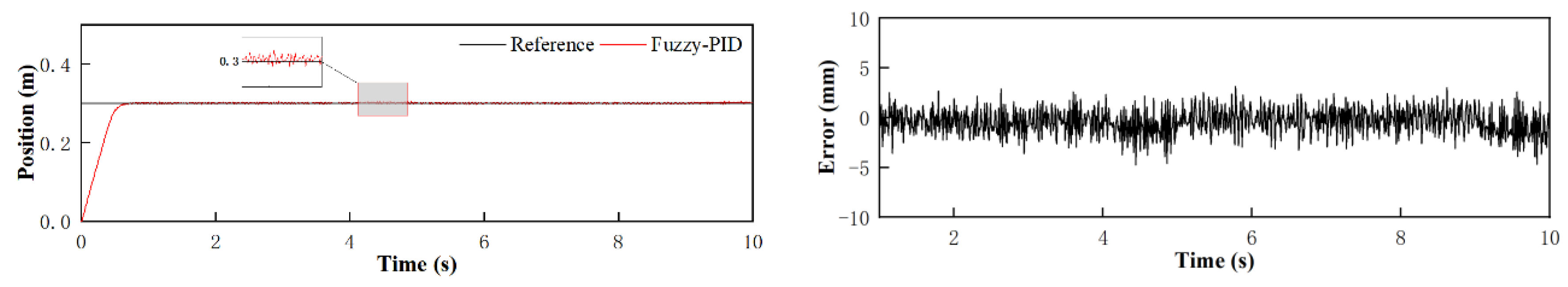
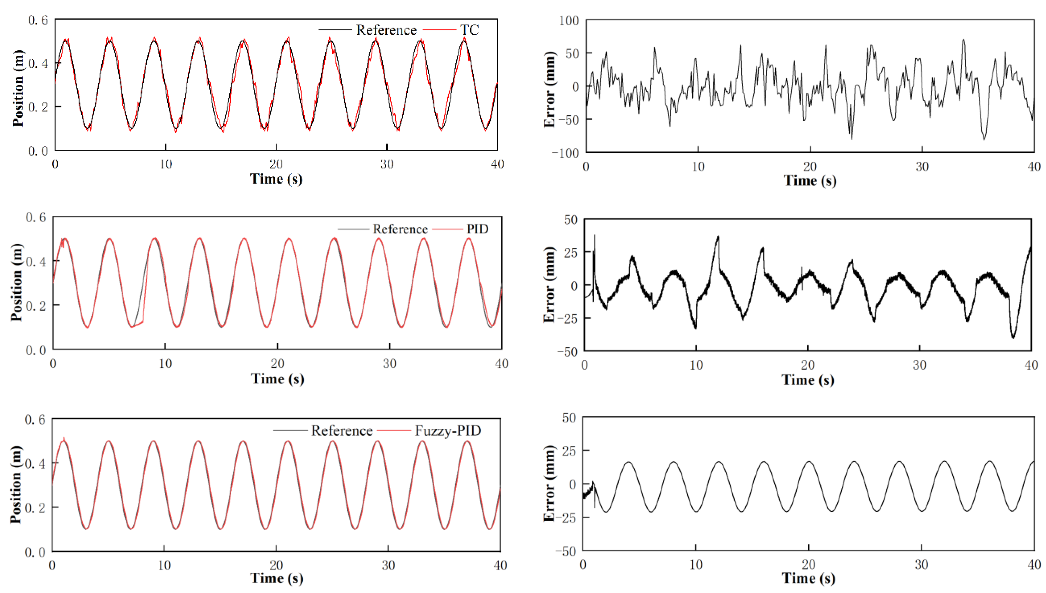
Through simulations and experiments, the results of the first set were obtained and are shown in Figure 15, the second set are given in Figure 16, and the third set are depicted in Figure 17. In addition, their performance indices are presented in Table 3, Table 4 and Table 5, respectively, where , , and are the indices of the average, maximum, and standard deviation of the tracking errors, respectively, and is the average output of the controller.
As shown in Figure 15, the three controllers have different overshoots under the trigger of the step signal, where TC is the largest and Fuzzy-PID is the smallest. Since there is no preprocessing with the steady-state error and response speed in TC, the performance of TC is worse than the other two controllers. By comparing the performance indices of the three controllers, although the of TC is the smallest, the forging hammer system with TC has a poor anti-interference ability and large fluctuations of up to 9 mm, having a great influence on the machining accuracy. Due to combining the reference signal and the feedback signal, PID possesses a certain robustness for dealing with the interference items and some uncertainties to some extent, thereby reducing the steady-state error and improving the response speed of the hydraulic system. However, PID is worse than Fuzzy-PID in terms of all indices. Namely, the proposed fuzzy-PID achieves the best control performance. By online self-tuning of the PID parameters according to the deviation between the reference and the real-time measured data, and were significantly reduced compared with PID. The mean tracking error and the maximum tracking error was reduced to less than 2.59 and 6.42 mm with less control efforts compared with PID controller, respectively.
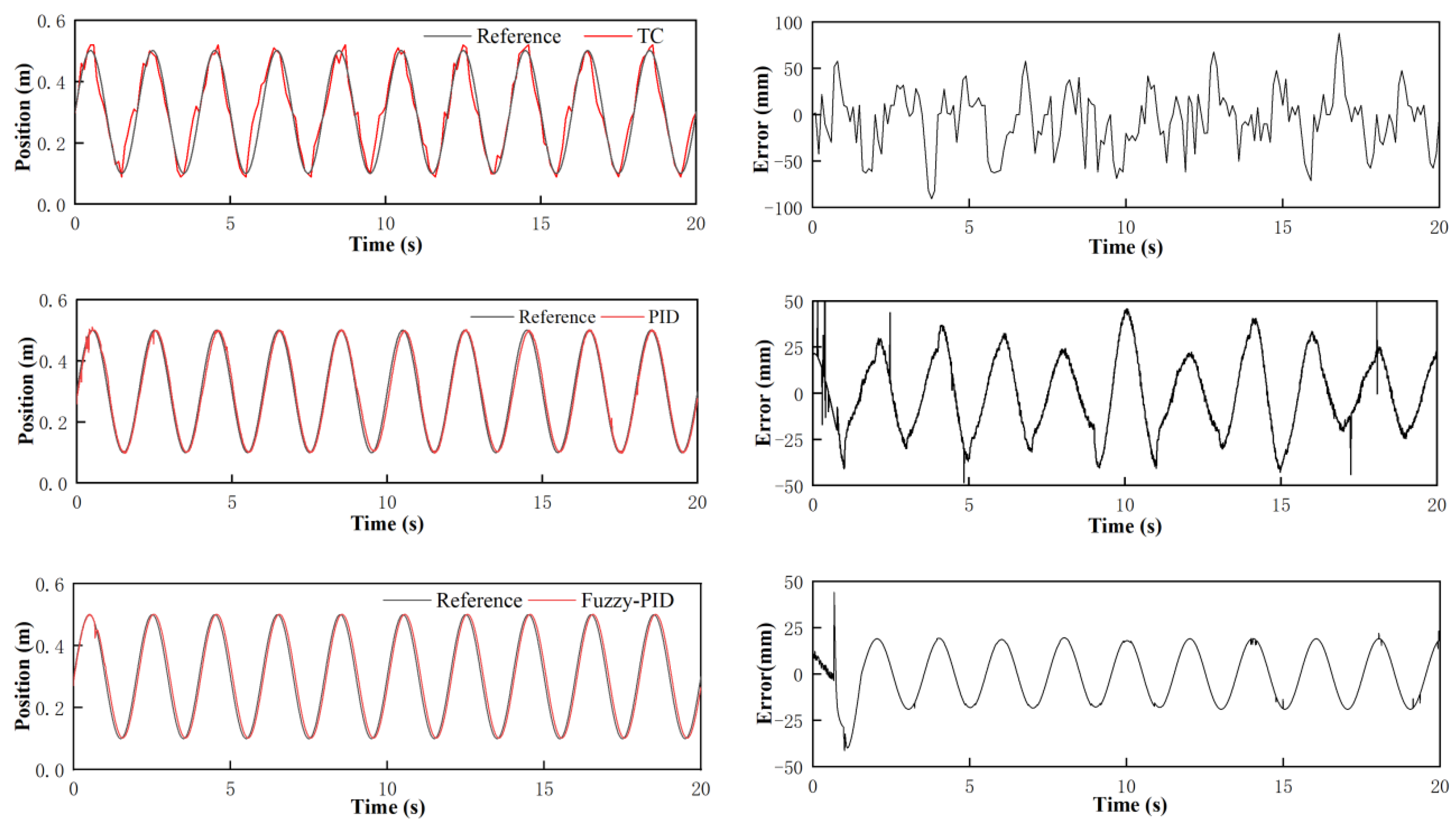
To further test the dynamic performance and the steady-state performance of the proposed free-forging hammer system, the hammerhead was moved along a sinusoidal trajectory. Figure 16 gives the tracking results of tracking with the three controllers compared and their performance indices are presented in Table 4. Compared with Fuzzy-PID, TC and PID produced large overshoots in each stroke, and the hammerhead fluctuated greatly during the downward stroke, leading to a tracking error of up to 70 mm and a low machining accuracy. However, things were significantly improved after adding fuzzy control, and as a result, the maximum overshoot of fuzzy-PID was only 1.6 mm.
In addition, in order to verify the processing performance of the proposed free forging hammer system under fast forging conditions, a fast forging sinusoidal trajectory was employed. According to experimental results presented in Figure 17 and Table 5, the fuzzy-PID controller designed outperforms the other two controllers in terms of the control accuracy and final tracking performance. Based on fuzzy control rules, the overshoot and steady-state error of fuzzy-PID are much smaller than those of conventional PID, and the system fluctuates smoothly. The maximum tracking error is only 22.98 mm. This further proves the effectiveness of the fuzzy-PID control algorithm in improving the processing performance of the all-hydraulic electro-hydraulic servo forging hammer.
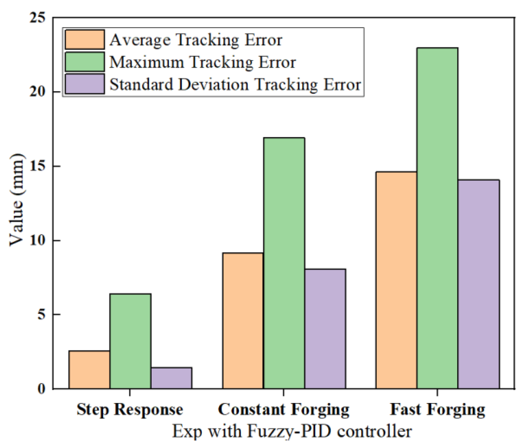
In general, the above three sets of experiments have respectively discussed three common working conditions in the free forging process, i.e., constant forging, fast forging, and step response forging, and Fuzzy-PID controller achieves the best performance among the three controllers, as shown in Figure 18. As can be seen from the above-obtained hammerhead motion trajectory, the hammerhead can move according to the given signal, no matter which control method is adopted, further verifying the effectiveness of the proposed automatic electro-hydraulic servo free forging hammer. By swinging the handle or setting the strike energy and frequency of the system on the upper computer, getting rid of the traditional manual drive and realizing the automatic and remote control of the forging hammer could be achieved. Meanwhile, the forging hammer system monitors the movement positions of the main working cylinder and the servo-driven cylinder, and sends the control signal of the next action after analyzing and processing the given signal, so the processing accuracy of the open forging hammer can be significantly improved.
6. Conclusions
A fuzzy-PID-based nonlinear servo control system has been proposed in this paper for the free forging hammer. The proposed method can address the harsh production environment of the free forging process, backward control methods, low processing accuracy, and inability to adapt to modern production. Changing the traditional control system of free forging hammers has achieved a reduction in personnel and increased the efficiency, which has brought new vitality to the forging hammer and its industry. The effectiveness of the presented method has been verified through serval sets of comparative experiments. Based on the theoretical analysis, simulations, and experiments presented in this paper, the following conclusions can be drawn.
- (1)
- Automatic control scheme
A closed-loop control system composed of PLC, an electrohydraulic servo valve, a servo cylinder, and feedback sensors was used to drive the follow-up control valve that controls the motion of the forging hammerhead. Since the reference instruction and the position feedback were employed, the striking energy of each stroke is controlled by the designed controller according to the forging size of the selected pass. After the strike is completed, the hammerhead automatically returns to its original position, and the forging process is completed automatically.
- (2)
- High machining accuracy
Based on fuzzy logic rules and PID control methods, high precision control of the striking energy is realized, and the maximum machining error was reduced to 22 mm, which was at least 50 mm less than the traditional free forging hammer.
- (3)
- Configuration and structure optimization
Accurate measurement of the real-time position of the hammerhead and the servo cylinder is a key factor for ensuring successful automatic control. As detecting sensors cannot be installed successfully and the measurement data contain a lot of noise due to the vibration and shock generated during the striking process, this paper proposes a non-contact measurement system to address this problem. In addition, optimization of the hammer structure has been achieved for this detecting system and the servo driving system.
Supplementary Materials
The following are available online at https://0-www-mdpi-com.brum.beds.ac.uk/2076-3417/10/24/9127/s1, Video S1: Automatic Free forging hammers, Video S2: Traditional Free Forging Hammers.
Author Contributions
X.Y.: conceptualization, investigation, methodology, data curation, software, validation, experiment validation, writing—original draft. B.C.: funding acquisition, project administration, supervision, writing—review and editing. Both authors have read and agreed to the published version of the manuscript.
Funding
This research received no external funding.
Acknowledgments
This research is funded by Huazhong University of Science and Technology and Huawei machinery manufacturing Co. LTD.
Conflicts of Interest
The authors declare that they do not have any commercial or associative interest that represents a conflict of interest in connection with the work submitted.
References
- Ghaei, A.; Movahhedy, M.R. Die design for the radial forging process using 3D FEM. J. Mater. Process. Technol. 2006, 182, 534–539. [Google Scholar] [CrossRef]
- Gontarz, A.; Pater, Z.; Drozdowski, K. Forging on hammer of rim forging from titanium alloy Ti64Al4V. Arch. Metall. Mater. 2012, 57, 1239–1246. [Google Scholar] [CrossRef] [Green Version]
- Gontarz, A. Theoretical and experimental research of hammer forging process of rim from AZ31 magnesium alloy. Metalurgija 2014, 53, 645–648. [Google Scholar]
- Espinoza, E. Optimizing a Hammer Forging Progression for a Large Hand Tool. Master’s Thesis, Marquette University, Milwaukee, WI, USA, 2015; 337p. [Google Scholar]
- Altan, T. Hammers and Presses for Forging. ASM Handb. Form. Forg. 1993, 14, 24–36. [Google Scholar]
- Yao, J.; Cao, X.; Wang, P.; Kong, X. Multi-Level Pressure Switching Control and Energy Saving for Displacement Servo Control System. In Proceedings of the BATH/ASME 2016 Symposium on Fluid Power and Motion Control, Bath, England, 7–9 September 2016. [Google Scholar]
- Kong, X.D.; Luo, H.; Quan, L.; Lu, J.; Zhang, Q. Analysis of force closed-loop control characteristics of 0.6MN free-forging hydraulic press. China Mech. Eng. 2015, 22, 3087–3096. [Google Scholar]
- Li, H.; Kong, X.D.; Liu, J. Research on neural network self-tuning PID control strategy for rolling force control system of skin pass mill. Mach. Toll Hydrualics 2010, 38, 67–70. [Google Scholar]
- Li, G.; Ding, Y.; Feng, Y.; Zhou, B.; Li, Y. Research on the control scheme of direct drive electro-hydraulic position servo system. In Proceedings of the International Conference on Electronic & Mechanical Engineering & Information Technology, Harbin, China, 12–14 August 2011. [Google Scholar]
- Gerretsen, A.; Mulder, M.; Van Paassen, M.M. Comparison of position-loop, velocity-loop and force-loop Based Control Loading Architecture. In Proceedings of the AIAA Modeling and Simulation Technologies Conference and Exhibit, San Francisco, CA, USA, 15–18 August 2005; pp. 1–18. [Google Scholar]
- Lizalde, C.; Loukianov, A.; Sánchez, E. Force tracking neural control for an electro-hydraulic actuator via second order sliding mode. In Proceedings of the 2005 IEEE International Symposium on, Mediterrean Conference on Control and Automation, Limassol, Cyprus, 27–29 June 2015; pp. 292–297. [Google Scholar]
- Alleyne, A.; Liu, R. A simplified approach to force control for electro-hydraulic systems. Control. Eng. Pr. 2000, 8, 1347–1356. [Google Scholar] [CrossRef]
- Zhang, Y.; Liu, F. The Research of Hydraulic Control System for Die Forging Hammer. China Met. Form. Equip. Manuf. Technol. 2010, 1, 68–71. [Google Scholar] [CrossRef]
- Jin, W.; Ma, W.; Yang, S. Simulation Research on Impact Energy of 50kJ Hydraulic Die Forging Hammer. Met. Equip. Manuf. Technol. 2008, 5, 90–92. [Google Scholar]
- Zhang, X.; Li, W.; Li, S. Forging process optimization of precision closed die forging hammer. MW Met. Form. 2018, 11, 76–77. [Google Scholar]
- Li, Y.R.; Yang, K.Y.; Ni, Z.L. A new model for calculating the maximum blow force of a die-forging hammer. J. Mater. Process. Technol. 1997, 71, 414–417. [Google Scholar] [CrossRef]
- Jonas, H. Influence of friction on die filling in counterblow hammer forging. J. Mater. Process. Technol. 2000, 108, 21–25. [Google Scholar]
- Ren, T.; Zhang, W.; Xue, X. Study on the fatigue damage characteristics of foundation soil under hammer blows. J. Hydraul. Eng. 2013, 191–197. [Google Scholar]
- Lavrinenko, V.Y.; Shagaleev, R.R. Practical investigation into piercing process using forging hammer head with filling. Mater. Today Proc. 2019, 19, 1823–1825. [Google Scholar] [CrossRef]
- Irisarri, A.M.; Pelayo, A. Failure analysis of an open die forging drop hammer. Eng. Fail. Anal. 2009, 16, 1727–1733. [Google Scholar] [CrossRef]
Figure 1.
Site operation of free forging hammer.

Figure 2.
Schematic diagram of the all-hydraulic free forging hammer. (1: hammerhead; 2: relief valve; 3: working cylinder; 4: manual spool valve; 5: accumulator group; 6: hydraulic power unit).
Figure 2.
Schematic diagram of the all-hydraulic free forging hammer. (1: hammerhead; 2: relief valve; 3: working cylinder; 4: manual spool valve; 5: accumulator group; 6: hydraulic power unit).

Figure 3.
Schematic diagram of the electro-hydraulic servo control system. (1: main control valve; 2: servo hydraulic cylinder; 3: displacement sensor; 4: servo valve).
Figure 3.
Schematic diagram of the electro-hydraulic servo control system. (1: main control valve; 2: servo hydraulic cylinder; 3: displacement sensor; 4: servo valve).

Figure 4.
Control diagram of the electro-hydraulic free forging hammer.

Figure 5.
(a) Configuration of the proposed free forging hammer; (b) sectional view of the proposed hammer.
Figure 5.
(a) Configuration of the proposed free forging hammer; (b) sectional view of the proposed hammer.

Figure 6.
Schematic diagram of the main control valve.

Figure 7.
(a) Driving mechanism based on a single-acting servo cylinder; (b) Double-acting servo cylinder; (c) Double-rod servo cylinder.
Figure 7.
(a) Driving mechanism based on a single-acting servo cylinder; (b) Double-acting servo cylinder; (c) Double-rod servo cylinder.

Figure 8.
Flow chart of AMESim simulations.

Figure 9.
The physical simulation model of the main system.

Figure 10.
Response characteristics of the electrohydraulic servo all-hydraulic forging hammer.

Figure 11.
Automatic control system of the free forging hammer.

Figure 12.
Principle of fuzzy-PID control system.

Figure 13.
(a) membership curves of , , ; (b) membership curves of and .


Figure 14.
Experimental platform of 8 MN program-controlled free forging hammer.

Figure 15.
Experiments of unit step response characteristics.


Figure 16.
Experiments of normal-level trajectory motions (Constant Forging).

Figure 17.
Experiments of fast-level trajectory motions (Fast Forging).

Figure 18.
Tracking error of Fuzzy-PID-Based nonlinear control systems.


Table 1.
Main parameters in simulation model.
| Parameters | Values | Units |
|---|---|---|
| Duty cycle pressure | 14 | MPa |
| Piston rod diameter (Servo cylinder) | 45 | mm |
| Piston diameter (Servo cylinder) | 65 | mm |
| Main control valve diameter | 190 | mm |
| Main cylinder diameter | 140 | mm |
| Length of stoke | −30–+30 | mm |
| Accumulator Volume | 10 | m3 |
| Gas pressure of Accumulator | 14 | MPa |
| Control signal | 0–40 | mA |
Table 2.
Control rules of , and .
| e/ec | NB | NM | NS | Z | PS | PM | PB |
|---|---|---|---|---|---|---|---|
| NB | PB/NB/PS | PB/NB/NS | PM/NM/NB | PM/NM/NB | PS/NS/NB | Z/Z/NM | Z/Z/PS |
| NM | PB/NB/PS | PB/NB/NS | PM/NM/NB | PS/NS/NM | PS/NS/NM | Z/Z/NS | NS/Z/Z |
| NS | PM/NB/Z | PM/NM/NS | PM/NS/NM | PS/NS/NM | Z/Z/NS | NS/PS/NS | NS/PS/Z |
| Z | PM/NM/Z | PM/NM/NS | PS/NS/NS | Z/Z/NS | NS/PS/NS | NM/PM/NS | NM/PM/Z |
| PS | PS/NM/Z | PS/NS/Z | Z/Z/Z | NS/PS/Z | NS/PS/Z | NM/PM/Z | NM/PB/Z |
| PM | PS/Z/PB | Z/Z/NS | NS/PS/PS | NM/PS/PS | NM/PM/PS | NM/PB/PS | NB/PB/PB |
| PB | Z/Z/PB | Z/Z/PM | NM/PS/PM | NM/PM/PM | NM/PM/PS | NB/PB/PS | NB/PB/PB |
Table 3.
Indices for the first set of experiments.
| Indices | ||||
|---|---|---|---|---|
| TC | 1.09 | 9.70 | 3.65 | 0.89 |
| PID | 5.57 | 7.97 | 2.90 | 0.92 |
| Fuzzy-PID | 2.59 | 6.42 | 1.45 | 0.89 |
Table 4.
Indices for the second set of experiments.
| Indices | ||||
|---|---|---|---|---|
| TC | 19.79 | 70.81 | 26.74 | 1.52 |
| PID | 11.23 | 38.47 | 12.20 | 1.50 |
| Fuzzy-PID | 9.18 | 16.93 | 8.09 | 1.43 |
Table 5.
Indices for the third set of experiments.
| Indices | ||||
|---|---|---|---|---|
| TC | 7.56 | 87.56 | 32.49 | 1.75 |
| PID | 21.48 | 59.70 | 20.53 | 1.73 |
| Fuzzy-PID | 14.63 | 22.98 | 14.10 | 1.68 |
Publisher’s Note: MDPI stays neutral with regard to jurisdictional claims in published maps and institutional affiliations. |
© 2020 by the authors. Licensee MDPI, Basel, Switzerland. This article is an open access article distributed under the terms and conditions of the Creative Commons Attribution (CC BY) license (http://creativecommons.org/licenses/by/4.0/).
Share and Cite
MDPI and ACS Style
Yan, X.; Chen, B. Analysis of a Novel Automatic Control Approach for the Free Forging Hammer. Appl. Sci. 2020, 10, 9127. https://0-doi-org.brum.beds.ac.uk/10.3390/app10249127
AMA Style
Yan X, Chen B. Analysis of a Novel Automatic Control Approach for the Free Forging Hammer. Applied Sciences. 2020; 10(24):9127. https://0-doi-org.brum.beds.ac.uk/10.3390/app10249127
Chicago/Turabian StyleYan, Xiaopeng, and Baijin Chen. 2020. "Analysis of a Novel Automatic Control Approach for the Free Forging Hammer" Applied Sciences 10, no. 24: 9127. https://0-doi-org.brum.beds.ac.uk/10.3390/app10249127
Note that from the first issue of 2016, this journal uses article numbers instead of page numbers. See further details here.